EP4534026A2 - Catheter device - Google Patents
Catheter device Download PDFInfo
- Publication number
- EP4534026A2 EP4534026A2 EP25158473.6A EP25158473A EP4534026A2 EP 4534026 A2 EP4534026 A2 EP 4534026A2 EP 25158473 A EP25158473 A EP 25158473A EP 4534026 A2 EP4534026 A2 EP 4534026A2
- Authority
- EP
- European Patent Office
- Prior art keywords
- rotor
- pump
- catheter device
- distal
- drive shaft
- Prior art date
- Legal status (The legal status is an assumption and is not a legal conclusion. Google has not performed a legal analysis and makes no representation as to the accuracy of the status listed.)
- Pending
Links
Images


Classifications
-
- A—HUMAN NECESSITIES
- A61—MEDICAL OR VETERINARY SCIENCE; HYGIENE
- A61M—DEVICES FOR INTRODUCING MEDIA INTO, OR ONTO, THE BODY; DEVICES FOR TRANSDUCING BODY MEDIA OR FOR TAKING MEDIA FROM THE BODY; DEVICES FOR PRODUCING OR ENDING SLEEP OR STUPOR
- A61M60/00—Blood pumps; Devices for mechanical circulatory actuation; Balloon pumps for circulatory assistance
- A61M60/40—Details relating to driving
- A61M60/403—Details relating to driving for non-positive displacement blood pumps
- A61M60/419—Details relating to driving for non-positive displacement blood pumps the force acting on the blood contacting member being permanent magnetic, e.g. from a rotating magnetic coupling between driving and driven magnets
-
- A—HUMAN NECESSITIES
- A61—MEDICAL OR VETERINARY SCIENCE; HYGIENE
- A61M—DEVICES FOR INTRODUCING MEDIA INTO, OR ONTO, THE BODY; DEVICES FOR TRANSDUCING BODY MEDIA OR FOR TAKING MEDIA FROM THE BODY; DEVICES FOR PRODUCING OR ENDING SLEEP OR STUPOR
- A61M60/00—Blood pumps; Devices for mechanical circulatory actuation; Balloon pumps for circulatory assistance
- A61M60/10—Location thereof with respect to the patient's body
- A61M60/122—Implantable pumps or pumping devices, i.e. the blood being pumped inside the patient's body
- A61M60/126—Implantable pumps or pumping devices, i.e. the blood being pumped inside the patient's body implantable via, into, inside, in line, branching on, or around a blood vessel
- A61M60/13—Implantable pumps or pumping devices, i.e. the blood being pumped inside the patient's body implantable via, into, inside, in line, branching on, or around a blood vessel by means of a catheter allowing explantation, e.g. catheter pumps temporarily introduced via the vascular system
-
- A—HUMAN NECESSITIES
- A61—MEDICAL OR VETERINARY SCIENCE; HYGIENE
- A61M—DEVICES FOR INTRODUCING MEDIA INTO, OR ONTO, THE BODY; DEVICES FOR TRANSDUCING BODY MEDIA OR FOR TAKING MEDIA FROM THE BODY; DEVICES FOR PRODUCING OR ENDING SLEEP OR STUPOR
- A61M60/00—Blood pumps; Devices for mechanical circulatory actuation; Balloon pumps for circulatory assistance
- A61M60/20—Type thereof
- A61M60/205—Non-positive displacement blood pumps
- A61M60/216—Non-positive displacement blood pumps including a rotating member acting on the blood, e.g. impeller
- A61M60/237—Non-positive displacement blood pumps including a rotating member acting on the blood, e.g. impeller the blood flow through the rotating member having mainly axial components, e.g. axial flow pumps
-
- A—HUMAN NECESSITIES
- A61—MEDICAL OR VETERINARY SCIENCE; HYGIENE
- A61M—DEVICES FOR INTRODUCING MEDIA INTO, OR ONTO, THE BODY; DEVICES FOR TRANSDUCING BODY MEDIA OR FOR TAKING MEDIA FROM THE BODY; DEVICES FOR PRODUCING OR ENDING SLEEP OR STUPOR
- A61M60/00—Blood pumps; Devices for mechanical circulatory actuation; Balloon pumps for circulatory assistance
- A61M60/80—Constructional details other than related to driving
- A61M60/802—Constructional details other than related to driving of non-positive displacement blood pumps
- A61M60/804—Impellers
- A61M60/806—Vanes or blades
- A61M60/808—Vanes or blades specially adapted for deformable impellers, e.g. expandable impellers
-
- A—HUMAN NECESSITIES
- A61—MEDICAL OR VETERINARY SCIENCE; HYGIENE
- A61M—DEVICES FOR INTRODUCING MEDIA INTO, OR ONTO, THE BODY; DEVICES FOR TRANSDUCING BODY MEDIA OR FOR TAKING MEDIA FROM THE BODY; DEVICES FOR PRODUCING OR ENDING SLEEP OR STUPOR
- A61M60/00—Blood pumps; Devices for mechanical circulatory actuation; Balloon pumps for circulatory assistance
- A61M60/80—Constructional details other than related to driving
- A61M60/802—Constructional details other than related to driving of non-positive displacement blood pumps
- A61M60/81—Pump housings
-
- A—HUMAN NECESSITIES
- A61—MEDICAL OR VETERINARY SCIENCE; HYGIENE
- A61M—DEVICES FOR INTRODUCING MEDIA INTO, OR ONTO, THE BODY; DEVICES FOR TRANSDUCING BODY MEDIA OR FOR TAKING MEDIA FROM THE BODY; DEVICES FOR PRODUCING OR ENDING SLEEP OR STUPOR
- A61M60/00—Blood pumps; Devices for mechanical circulatory actuation; Balloon pumps for circulatory assistance
- A61M60/80—Constructional details other than related to driving
- A61M60/802—Constructional details other than related to driving of non-positive displacement blood pumps
- A61M60/818—Bearings
- A61M60/825—Contact bearings, e.g. ball-and-cup or pivot bearings
-
- A—HUMAN NECESSITIES
- A61—MEDICAL OR VETERINARY SCIENCE; HYGIENE
- A61M—DEVICES FOR INTRODUCING MEDIA INTO, OR ONTO, THE BODY; DEVICES FOR TRANSDUCING BODY MEDIA OR FOR TAKING MEDIA FROM THE BODY; DEVICES FOR PRODUCING OR ENDING SLEEP OR STUPOR
- A61M60/00—Blood pumps; Devices for mechanical circulatory actuation; Balloon pumps for circulatory assistance
- A61M60/10—Location thereof with respect to the patient's body
- A61M60/122—Implantable pumps or pumping devices, i.e. the blood being pumped inside the patient's body
- A61M60/126—Implantable pumps or pumping devices, i.e. the blood being pumped inside the patient's body implantable via, into, inside, in line, branching on, or around a blood vessel
- A61M60/148—Implantable pumps or pumping devices, i.e. the blood being pumped inside the patient's body implantable via, into, inside, in line, branching on, or around a blood vessel in line with a blood vessel using resection or like techniques, e.g. permanent endovascular heart assist devices
-
- A—HUMAN NECESSITIES
- A61—MEDICAL OR VETERINARY SCIENCE; HYGIENE
- A61M—DEVICES FOR INTRODUCING MEDIA INTO, OR ONTO, THE BODY; DEVICES FOR TRANSDUCING BODY MEDIA OR FOR TAKING MEDIA FROM THE BODY; DEVICES FOR PRODUCING OR ENDING SLEEP OR STUPOR
- A61M60/00—Blood pumps; Devices for mechanical circulatory actuation; Balloon pumps for circulatory assistance
- A61M60/40—Details relating to driving
- A61M60/403—Details relating to driving for non-positive displacement blood pumps
- A61M60/408—Details relating to driving for non-positive displacement blood pumps the force acting on the blood contacting member being mechanical, e.g. transmitted by a shaft or cable
- A61M60/411—Details relating to driving for non-positive displacement blood pumps the force acting on the blood contacting member being mechanical, e.g. transmitted by a shaft or cable generated by an electromotor
- A61M60/414—Details relating to driving for non-positive displacement blood pumps the force acting on the blood contacting member being mechanical, e.g. transmitted by a shaft or cable generated by an electromotor transmitted by a rotating cable, e.g. for blood pumps mounted on a catheter
-
- A—HUMAN NECESSITIES
- A61—MEDICAL OR VETERINARY SCIENCE; HYGIENE
- A61M—DEVICES FOR INTRODUCING MEDIA INTO, OR ONTO, THE BODY; DEVICES FOR TRANSDUCING BODY MEDIA OR FOR TAKING MEDIA FROM THE BODY; DEVICES FOR PRODUCING OR ENDING SLEEP OR STUPOR
- A61M60/00—Blood pumps; Devices for mechanical circulatory actuation; Balloon pumps for circulatory assistance
- A61M60/80—Constructional details other than related to driving
- A61M60/802—Constructional details other than related to driving of non-positive displacement blood pumps
- A61M60/827—Sealings between moving parts
- A61M60/829—Sealings between moving parts having a purge fluid supply
Definitions
- the invention relates to a catheter device, in particular a catheter device with an elongated drive shaft.
- a well-known transfemoral implantable micro-axial pump the "Hemopump TM” from Medtronic Inc., USA, has been shown, after experimental and preliminary clinical trials, to be a promising concept that can provide sufficient left ventricular relief.
- the pump's intake port is placed retrogradely over the aortic valve in the left ventricle.
- the pump rotor is located at the end of a cannula in the superior descending aorta and is driven by an external motor.
- the disadvantage of this system is that, due to the rotor's large diameter, transfemoral implantation is only possible surgically via a femoral artery graft and, if necessary, by grafting.
- the result is an axial pump that can be inserted through a patient's vascular system.
- the axial pump has a flexible, compressible tube that forms the pump housing.
- a radially compressible rotor is located within the tube.
- the rotor's drive shaft runs through a catheter.
- the catheter, together with the tube and rotor, can be pulled into a cover tube.
- the radial compressibility of the components allows for the realization of a puncture diameter that is acceptable for percutaneous implantation using the Seldinger technique.
- a relatively large pump diameter of 10 to 14 mm can be provided. This reduces the rotor speed and thus the mechanical stress on the components.
- the pump has a drive part and a pump part, which have such a small diameter that they can be pushed through a blood vessel.
- a flexible cannula is connected to the pump part.
- the cannula can be expanded to a diameter that is larger than that of the drive part or the pump part.
- the cannula is constricted, in which it has a small diameter. In the blood vessel, it is expanded so that it offers less flow resistance for the blood to be pumped.
- a catheter with an integrated blood pump is described.
- a flexible rim extends over a tubular section of the catheter and contacts the walls of the aorta, ensuring that all blood within the aorta flows through the pump.
- the flexible, expandable rim also distances the pump from the aortic valve.
- the present invention is based on the object of creating a catheter device with a drive shaft extending almost over the entire catheter device, which can be reliably driven at high speed.
- the magnetic ring bearing or rather the magnetic connection between the two magnet units, limits the contribution of the transmittable torque. As soon as the adjustable torque is exceeded, the two magnet units separate.
- the catheter device comprises a tubular catheter shaft that surrounds the drive shaft and extends from the proximal end region to the distal end region of the catheter device.
- the catheter shaft is connected to the coupling housing at its proximal end in a fluid-tight manner.
- a flushing hole in the coupling housing allows the introduction of a flushing medium to lubricate the drive shaft and the output-side coupling elements. This prevents blood from penetrating the area between the drive shaft and the catheter shaft and impairing the rotation of the drive shaft.
- a coupling element on the output side supporting the distal magnet unit is supported by a plain bearing. This allows the distance between the two magnet units to be precisely determined.
- the maximum torque that can be transmitted by the magnetic coupling is set both by the distance between the two magnetic units determined by the plain bearing and by the force with which the coupling element is subjected in the axial direction by the magnetic ring bearing.
- the diameter of the drive shaft can range from 0.3 mm to 1 mm, and is preferably approximately 0.4 mm to 0.6 mm. The smaller the diameter of the drive shaft, the higher the rotational speed at which the drive shaft is driven by the motor can be.
- the element rotating by means of the drive shaft can be a rotor, a milling tool or another tool.
- Such a rotor is preferably designed to be self-expanding. It can be provided with a pump housing that, like the rotor, can be compressed to a small diameter. According to a preferred embodiment, the rotor and the pump housing are made of a shape-memory material.
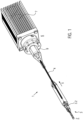
- Figure 1 shows a catheter device 1.
- the catheter device 1 according to the invention represents a pump.
- the catheter device 1 has a pump head 3 at a distal end 2.
- the pump head 3 has a rotor 3.2 for conveying a medium in the conveying direction 5, which is connected to a drive shaft 4.
- the conveying direction 5 is directed from the distal end 2 to a proximal end 6.
- a motor 7 is arranged at the proximal end 6, which is spaced from the pump head 3.
- the drive shaft 4 is surrounded by a catheter shaft 8 and is non-positively connected to the motor 7 by means of a coupling 9.
- the pump head 3 will be explained in more detail below.
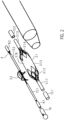
- the pump head 3 comprises a shaft cap 10 at the distal end, the rotor 3.2 arranged on the drive shaft 4, a pump housing 3.1, and an outflow hose 18.
- the butt cap 10 is formed from a ball 10.1 with an attached cylindrical section 10.2.
- the butt cap 10 is made of stainless steel, for example ( Fig.2 , Fig.3
- the butt plate 10 could also be made of polyethylene PE, polypropylene PP, polyetheretherketone PEEK, polyvinyl chloride PVC, Teflon PTFE, acrylic glass, epoxy resin, polyurethane PU, carbon fiber, coated materials, composite materials, PEBAX, or a polyether block amide. In principle, all hemocompatible materials are suitable, since only low mechanical stress occurs on this component.
- the diameter of the ball 10.1 is approximately 3.2 mm.
- the cylindrical section 10.2 is approximately 5.5 mm long and has a diameter of approximately 2.2 mm.
- the total length of the butt plate is approximately 7.0 mm.
- the cylindrical section 10.2 has, at its distal end, in the connection area to the ball 10.1, a through-bore 10.3 arranged transversely to the conveying direction 5. Furthermore, the cylinder 10.2 has an axial bore 10.4 extending from the proximal end of the cylindrical section 10.2 to the ball 10.1, so that a communicating passage is formed from the through-bore 10.3 to the proximal end of the shaft cap 10. A step 10.5 is formed in the area of the axial bore 10.4, so that the axial bore is widened toward the proximal end.
- the through hole 10.3 prevents the formation of a blind hole in the shaft cap and also allows the attachment of a thread which is helpful when compressing the pump head 3.
- the tip of the shaft cap 10 is an atraumatic ball to protect the heart muscle (endocardium).
- the shaft cap 10 can be used to support the pump head 3 against the heart wall.
- a tubular or hose-shaped distal catheter shaft piece 8.1 is inserted from the proximal end into the shaft cap 10 up to the step.
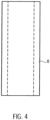
- the distal catheter shaft piece 8.1 is precisely received in the axial bore 10.4 and is fixed there ( Fig. 4 ).
- the distal catheter shaft piece 8.1 is made of polyurethane or another suitable material, in particular an elastic plastic material (e.g., PE, PVC, Teflon, elastomer).
- the distal end of the distal catheter shaft piece 8.1 is connected to the shaft cap 10.
- the connection can be formed as an adhesive connection using, for example, cyanoacrylate adhesive. or it is carried out as a welded, clamped, or shrink-fit connection.
- the distal catheter shaft piece 8.1 forms a straight, yet slightly flexible connection between the shaft cap 10 and the pump housing 3.1. This straight connection ensures coaxiality of all components arranged within it (drive shaft, shaft guard, housing, connecting bushing).
- the distal catheter shaft piece 8.1 in conjunction with the shaft cap 10, serves as a positioning aid for the pump head 3 when it is inserted into a vessel or the heart.
- the catheter shaft piece 8.1 in the present embodiment has a length of approximately 25 mm, an outer diameter of approximately 1.9 mm and an inner diameter of approximately 1.3 mm.
- the distal connecting bushing 12.1 has a length of approximately 5 mm and an outer diameter of approximately 2.2 mm.
- the diameter in the distal region is approximately 2 mm and in the proximal region approximately 1.5 mm. The shorter the connecting bushing, the less stiffening it provides.
- the distal and an analogously designed proximal connecting bushing 12.1, 12.2 are made, for example, of stainless steel, copper, brass, titanium or another suitable metal, of polyethylene (PE), polypropylene (PP), Teflon (PTFE), PEBAX, a polyether block amide, or another suitable material.
- the expandable or compressible pump housing 3.1 is a tubular lattice structure 3.1.6 made of Nitinol or another suitable shape memory alloy or another shape memory material, e.g., plastic, iron alloy, copper alloy.
- the pump housing 3.1 is divided into five sections from distal to proximal ( Fig. 8 ).
- the first distal section is a tubular distal connecting section 3.1.1.
- a second section is a suction section 3.1.2 which widens conically in the conveying direction 5.
- a pump section 3.1.3 is connected to the suction section 3.1.2.
- the tubular pump section 3.1.3 accommodates the rotor 3.2.
- the inner diameter of the pump section 3.1.3 in the expanded state is approximately 6.15 mm.
- large diamonds 3.1.7.2 are provided, which have approximately four times the edge length of the small diamonds 3.1.7.1.
- the large diamonds 3.1.7.2 are combined into smaller diamonds.
- medium-sized diamonds 3.1.7.3 are provided, which have approximately twice the edge length of the small diamonds 3.1.7.1 ( Fig. 9 ).
- the design of the openings (3.1.7) and the number of multiplications can be arbitrary.
- the width of the lattice struts is increased. This keeps the strength of the lattice struts roughly the same, or even increases it toward the larger diamonds.
- the grid structure 3.1.6 of the pump housing 3.1 is covered with a PU covering 3.1.8 in the pump section 3.1.3, whereby the grid openings are sealed liquid-tight.
- a covering other than PU can also be used, such as PE, PP, silicone or parylene, as long as it meets the mechanical and geometric requirements.
- the performance parameters of the pump including blood damage, can be specifically controlled.
- the polygonal structure and the special design of the PU covering result in an almost round cross-sectional shape for the pump housing 3.1. In conjunction with the round rotor 3.2, this results in very small gaps between the rotor 3.2 and the pump housing 3.1. This leads to comparatively low Blood damage, low leakage currents, and good efficiency.
- the 3.1.6 lattice structure results in very good radial and axial stability, as well as excellent axial compressibility and expandability.
- the special structure allows for easy adjustment of length and diameter to meet performance requirements.
- the proximal connecting section 3.1.5 of the pump housing 3.1 is received in the proximal connecting socket 12.2 and connected to it.
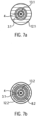
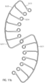
- a tubular proximal catheter shaft piece 8.2 is received in the proximal connecting socket 12.2 and connected to it ( Fig. 7a, Fig. 7b ).
- the same connection types described above can be used.
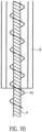
- a distal shaft protector 13.1 and a proximal shaft protector 13.2 are arranged in the axial direction ( Fig. 6 ).
- the distal and proximal shaft protection 13.1, 13.2 are designed as a tube made of PU or one of the other materials listed above.
- the distal shaft guard 13.1 extends in the pumping direction 5 from just before the distal connecting bushing 12.1 to the distal end of the pump section 3.1.3 of the pump housing 3.1, i.e., to the rotor 3.2.
- the proximal shaft guard 13.2 extends from the proximal end of the rotor 3.2 to just behind the proximal end of the proximal connecting bushing 12.1.
- the distal and proximal shaft protectors 13.1, 13.2 are connected to the distal and proximal connecting sleeves 12.1, 12.2 and the distal and proximal catheter shaft pieces 8.1, 8.2 in the two areas in which they are arranged within these.
- the connecting bushings 12.1, 12.2 ensure the axial centering of the drive shaft 4, particularly in the pump housing 3.1.
- the proximal shaft protection 13.1 ( Fig. 2 , Fig. 6 ) separates the proximal section 4.3 of the drive shaft 4 from the pump medium to protect against blood damage caused by the rotational movement of the drive shaft 4 and the adhesion of blood components to the drive shaft 4. This prevents the buildup of shear forces. There is no direct interaction between the drive shaft 4 and the blood due to the very small gap, and only minimal blood transport through this gap is possible.
- the distal and proximal shaft guards 13.1, 13.2 center and support the drive shaft 4 during operation and during the compression and expansion process.
- the drive shaft 4 is preferably formed from several, in particular six, wires (not shown), which are wound left- or right-hand around a core (not shown).
- the outer diameter of the drive shaft 4 is approximately 0.48 mm.
- the drive shaft 4 can also have a different number of cores and wires and a smaller or larger diameter.
- the diameter of the drive shaft can range from 0.3 mm to 1 mm and is preferably approximately 0.4 mm to 0.6 mm.
- the smaller the diameter of the drive shaft the higher the rotational speed can be, because the smaller the diameter, the lower the speed at which the circumference of the drive shaft moves relative to its surroundings. A high circumferential speed is problematic if the drive shaft comes into contact with the environment.
- the catheter device is designed for speeds of more than 20,000 rpm and up to 40,000 rpm. Therefore, the diameter of the drive shaft 4 is designed to be as small as possible, but thick enough to still have sufficient strength.
- the drive shaft 4 extends from the distal end of the distal shaft guard 13.1 in the conveying direction 5 behind the distal connecting bush 12.1 to the coupling 9.
- the spiral-shaped, expandable rotor 3.2 is arranged in a rotationally fixed manner on the drive shaft 4.
- the rotor 3.2 is a two-bladed, comb-shaped frame structure 3.2.1 made of Nitinol or another shape memory material, e.g., plastic (see above), which is coated with a PU skin or surrounded by it in a liquid-tight manner ( Fig. 11a ). This means that the covering, in the form of a PU skin, is stretched between the comb-shaped frame structure.
- the construction of the rotor 3.2 as a coated frame structure 3.2.1 made of Nitinol makes it possible to expand or compress the rotor 3.2.
- the PU skin is highly elastic, so it is not damaged during compression.
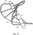
- the frame structure 3.2.1 has a circumferential, helical or spiral outer boundary frame 3.2.2 with several rotor struts 3.2.3 running radially inwards with the boundary frame 3.2.2 ( Fig. 12 ). Rings 3.2.4 are formed at the free ends of the rotor struts 3.2.3.
- the drive shaft 4 extends through the rings 3.2.4 of the rotor struts 3.2.3.
- the rotor 3.2 can also be made in one piece ( Fig. 11b ) or have several frame structures ( Fig. 11a ). Each frame structure forms a rotor blade.
- FIG. 11b and 12 A frame structure 3.2.1 for a rotor 3.2 is shown, which forms two rotor blades. If required, several rotor blades and accordingly Several frame structures 3.2.1 may be arranged on a rotor 3.2.
- the frame structure may also have any other suitable shape.
- the distance between two adjacent rings 3.2.4 is smaller than the corresponding section of the spiral-shaped boundary frame 3.2.2.
- the length of the spacer sleeves 16 can thus determine the pitch of the rotor 3.2. It can vary within a rotor 3.2.
- the pitch of rotor 3.2 is determined by the length or number of spacer sleeves 16 in relation to the dimensions of the circumferential, spiral-shaped outer boundary frame 3.2.2 between two rotor struts 3.2.3.
- the length of the spacer sleeves 16 can be uniform for all positions, but it can also be varied symmetrically or asymmetrically for each position. This complete design freedom allows for a very flexible design of rotor 3.2. This flexible design makes it possible to generate different conveying or pumping characteristics of rotor 3.2.
- the Rotor 3.2 exhibits high dimensional stability with flexible design options and minimal material usage (e.g., a thin frame structure). Maximum rigidity and stability are achieved. Nevertheless, the combination of the frame structure and the covering, which further supports the properties of the frame structure through stabilization, allows for very strong compression. This results in the rotor's excellent compressibility and expandability. The excellent surface formation of the PU skin on the lattice structure allows for a very good adaptation of the housing structure to the rotor structure.
- the rotor 3.2 In the compressed state, the rotor 3.2 has approximately the inner diameter of the compressed pump housing 3.1.
- the outer diameter of the compressed pump housing is approximately between 2 mm and 4 mm, and preferably approximately 3.3 mm.
- the spiral-shaped outer boundary frame 3.2.2 of the rotor 3.2 is slightly spaced from the inner surface of the pump housing 3.1.
- the distance between the outer boundary frame 3.2.2 and the inner surface of the pump housing 3.1 is approximately between 0.01 mm and 0.5 mm. The smaller the distance between the frame structure 3.2.1 and the inner surface of the pump housing 3.1, the higher the pumping capacity of the rotor 3.2.
- the distal spacer sleeve 16 of the rotor 3.2 contacts the bearing disk 15 in the manner of a plain bearing. In this way, a distal rotor bearing 17 is formed ( Fig.6 ).
- the drive shaft 4 is accommodated in the through hole of the bearing disc 15 with almost no play. Only small clearances (not shown) remain due to the design of the drive shaft 4.
- the drive shaft 4 is similarly received by a proximal connecting bushing 12.2 on the proximal end spacer sleeve 16 of the rotor 3.2.
- a tubular elastic discharge hose 18 is arranged ( Fig. 1 , Fig. 13 ).
- the outflow tube 18 is made of PU.
- the outflow tube 18 has a length of approximately 70 mm, a diameter of approximately 10 mm, and a wall thickness of approximately 0.01 mm to 0.1 mm, and preferably approximately 0.03 mm.
- the two ends of the outflow tube 18 are tapered, with a cylindrical section arranged at the proximal conical end of the outflow tube.
- the distal, tapered end of the outflow tube 18 forms a tight seal with the PU covering of the pump section 3.1.3 of the pump housing 3.1.
- the cylindrical proximal section is firmly connected to the proximal catheter shaft piece 8.2. Both are connected to each other in a fluid-tight manner using dissolved PU.
- outlet openings 18.1 are arranged radially around the circumference.
- the outlet openings 18.1 can, for example, be oval in the flow direction 5.
- the outlet openings can also be round, crescent-shaped, or have any desired geometry to generate other outlet flows.
- the outlet openings 18.1 swirl the blood exiting the aortic bulb. This prevents laminar flow and thus the water jet pump effect against the coronary arteries.
- the coupling 9 and the motor 7 are located at the proximal end of the catheter shaft 8.2.
- the distance between the pump head 3 and the coupling 9, or the length of the proximal catheter shaft section 8.2, can vary depending on the patient and is approximately 90 to 150 cm.
- a tubular cover tube 29 is arranged above the catheter device 1.
- the cover tube 29 is designed to surround the compressed pump head 3 and the proximal catheter shaft piece 8.2.
- the cover tube 29 holds the pump head 3 in its compressed state.
- the cover tube 29 is retracted from the fixed catheter device 1 until the pump head 3 is exposed.
- the pump housing 3.1 and rotor 3.2 expand radially outward due to the spring force of the elastic material. This means that the lattice structure 3.1.6 of the pump housing 3.1 and the frame structure 3.2.1 of the rotor 3.2 expand until they reach their predetermined diameter. It may also be possible to utilize the temperature effects of the memory material to assist in the expansion process.
- the cover tube 29 is advanced to the shaft cap 10, whereby the rotor 3.2 and the pump housing 3.1 are compressed and drawn into the cover tube, after which the cover tube is extracted through the puncture site.
- the clutch 9 is a magnetic clutch ( Fig. 14 , Fig. 15 ).
- the coupling 9 has a coupling housing 19 with a distal magnet unit 23.1.
- the coupling housing 19 is connected to the proximal catheter shaft piece 8.2, which forms a continuous cavity.
- the coupling housing 19 hermetically separates the proximal catheter shaft piece 8.2 from a motor assembly 30.
- the motor assembly 30 has a proximal magnet unit 23.2.
- the proximal magnet unit 23.2 is frictionally connected to the motor 7.
- the distal magnet unit 23.1 is connected to the drive shaft 4 via a coupling element 22.
- the distal magnet unit 23.1 and the proximal magnet unit 23.2 are coupled to each other via magnetic forces to prevent rotation.
- the two magnet units 23.1 and 23.2 ensure a force-locking connection with contact-free rotational force transmission.
- the coupling housing 19 has, from distal to proximal, a distal cylindrical section 19.1, a conically widening section 19.2, a second cylindrical section 19.3, and a proximal cylindrical section 19.4.
- the coupling housing is made, for example, of polymethylacrylate (PMMA) or another injection-moldable or machineable material.
- a through-bore is formed in the distal cylindrical section 19.1, centrally located in the axial direction.
- the through-bore extends through the entire coupling housing 19.
- the through-bore narrows in three stages from a first catheter shaft receiving section 19.5 to a second guide coil receiving section 19.6 and to a third drive shaft passage section 19.7.
- the proximal end of the proximal catheter shaft is arranged in the catheter shaft receiving section 19.5 of the coupling housing 19 and is firmly connected thereto.
- the guide coil 14 is received in the guide coil receiving section 19.6.
- the bearing section 19.9 has a diameter of approximately 10 mm.
- the bore of the distal coupling section 19.10 merges into a larger proximal coupling section 19.11.
- Eight M 1.6 threaded bores 19.13 are radially symmetrically formed in the shoulder 19.12 formed between the distal and proximal coupling sections 19.10 and 19.11.
- three L-shaped milled recesses 19.14 are arranged around the circumference.
- the distal coupling section 19.10 has a diameter of approximately 22 mm.
- the flushing bore 19.15 has a diameter of approximately 6.5 mm and the proximal coupling section 19.11 has a diameter of approximately 30 mm.
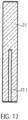
- the proximal end of the drive shaft 4 is connected to a cuboidal square rod 21 in a rotationally, tensile and compressively resistant manner (force-locking) ( Fig.17 ).
- the square rod 21 has a recess 21.1 for receiving the proximal end of the drive shaft 4.
- the drive shaft 4 is fixed in the recess.
- the square rod 21 is made of brass, for example, which has good lubricating properties.
- Other suitable materials include all materials that can be extruded or machined, such as PE, PP, PTFE, gold, silver, titanium, diamond, etc.
- the square bar 21 has a length of approximately 19.4 mm and a cross-section of approximately 2.88 mm x 2.88 mm.
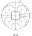
- the square rod 21 is axially displaceably received by an axial recess 22.1 within a rotationally symmetrical coupling element 22 ( Fig. 23 ). This enables it to compensate for length differences in the axial direction ( Fig. 18 ).
- the recess 22.1 is formed by a larger, central bore and four smaller bores arranged along the circumference of the central bore.
- the bores can be formed by drilling, erosion, ultrasonic drilling, laser drilling, or water jet drilling.
- More or fewer stop edges can also be provided.
- a square bar a triangular or pentagonal bar, or a profile bar with any cross-sectional area that remains constant in the longitudinal direction of the bar, can also be provided.
- the shape of the recess 22.1 must be adapted to the cross-sectional area of the profile bar.
- a shoulder 22.4 is formed at the distal outer end or circumference of the cylindrical section 22.2 of the coupling element 22.
- a second inner ring magnet 20.2 is arranged on this shoulder 22.4.
- the shoulder 22.4 accommodates the ring magnet 20.2 such that its outer surface is flush with the outer surface of the cylindrical section 22.2.
- the ring magnet forms a magnetic ring bearing 20.3.
- the two ring magnets 20.1, 20.2 are arranged such that, for example, the north pole of the outer ring magnet is oriented distally and the south pole proximally.
- the north and south poles of the inner ring magnet are correspondingly opposite each other. Accordingly, the north and south poles of the two ring magnets can also be reversed.
- the magnetic ring bearing 20.3 centers the drive shaft 4 in the axial and radial directions. Radial centering is achieved by the magnetic attraction forces in the radial direction.
- Axial centering is achieved by generating magnetic restoring forces when the inner ring magnet 20.2 is slightly misaligned, pulling the inner ring magnet 20.2 into a position that coincides with the axial position of the outer ring magnet 20.1. However, when the misalignment is greater, repulsive forces occur between the two magnetic rings 20.1 and 20.2, forcing them apart.
- the ring magnets 20.1 and 20.2 do not touch each other, meaning no lubrication is required.
- the magnetic ring bearing also has a vibration-damping effect.
- the centric circular milling 22.5 has a diameter of approximately 16.5 mm and a depth of approximately 3 mm.
- the magnet holder 22.5 accommodates the four-segmented annular distal magnet unit 23.1.
- the annular distal magnet unit is glued into the magnet holder 22.5.
- a ball-and-socket bearing receptacle 22.7 is formed centrally in the proximal end face of the coupling element 22.
- the ball-and-socket bearing receptacle 22.7 is an approximately hemispherical recess 22.7.
- the hemispherical recess 22.7 has a diameter of approximately 0.5 to 1.3 mm.
- the square rod 21 or the cylindrical section of the coupling element 22 is received by the fourth bore section 19.8 or the bearing section 19.9 of the coupling housing 19.
- the disc-shaped section 22.3 of the Coupling element 22 is received by the distal coupling section 19.10 of the coupling housing 19.
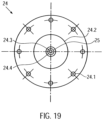
- the clutch housing 19 is hermetically separated from the motor assembly by a cover plate 24 ( Fig. 19 ).
- the clutch housing 19 is gas- and liquid-tight except for the flushing bore 19.15 in the clutch housing 22 and the spaces between the drive shaft passage section 19.7 and the drive shaft 4.
- the cover plate 24 On the distal side, the cover plate 24 has a central thickening 24.2. A through-hole 24.3 and a central hemispherical cutout 24.4 are formed in the center of the cover plate 24. A cylindrical centering pin 24.5 is fixed in the through-hole 24.3 ( Fig.21 ). On the centering pin 24.5 there is a ball head 24.6 which is accommodated in the hemispherical milling ( Fig. 15 , Fig. 20 ).
- a force is applied proximally to the distal magnet unit 23.1. These opposing forces produce a resulting force that presses the coupling element 22 against the ball head 24.6. This resulting force is adjusted so that the ball head 24.6 is securely mounted while still minimizing wear in the ball head bearing.
- the ball head 24.6 forms a ball head bearing 25 in conjunction with the distally arranged ball head bearing receptacle 22.7 of the coupling element 22.
- the ball head bearing 25 is a plain bearing.
- other plain bearings are also possible, such as a Tapered head bearings or cylindrical head bearings are possible, in which a cone or cylinder serves as the bearing body instead of a ball.
- the mount is adapted to the shape of the bearing body.
- the axial centering of the magnetic ring bearing 20.3 is achieved by positioning the inner ring magnet 20.2 not exactly centrally within the outer ring magnet 20.1 in the axial direction, but rather slightly offset proximally. This applies a distal force to the inner ring magnet 20.2.
- the ball head 24.6 can be made of ruby, aluminum oxide, or a hard plastic.
- the motor assembly comprises the proximal magnet unit 23.2, a proximal magnet holder 26, a coupling flange 27, a motor holder 7.1, with a cooling fan arranged thereon and the motor 7 ( Fig. 14 , Fig. 22 ).
- proximal magnet unit 23.2 On the proximal side of the cover plate 24, at a distance of approximately 0.5 to 8 mm and preferably approximately 1 to 2 mm, there is a proximal magnet unit 23.2 arranged axially aligned with the distal magnet unit 23.1.
- the proximal annular magnet unit 23.2 has four segments, similar to the distal magnet unit 23.1.
- the magnet holder 26 is disc-shaped and has a central circular cutout 26.1 on its distal side. Analogous to the distal magnet unit 23.1, four magnet segments are glued into the cutout 26.1 using a two-component epoxy resin adhesive or cyanoacrylate adhesive (see above).
- the four segments of the distal and proximal magnet units 23.1, 23.2 can be designed as curved bar magnets, each with a different polarity at their end regions.
- the four segments can also be designed as four quarters of a curved ring magnet.
- the segments can also be designed as short, axially aligned bar magnets arranged in a ring. More than four segments can also be provided. In the initial position, the two magnets are arranged such that a north and a south pole of the bar magnets of the two magnet units 23.1, 23.2 overlap and attract each other.
- the four segments are arranged four times with their north and south poles alternating in abutment, so that the segments of a magnet unit attract each other.
- the distal and proximal magnet units 23.1, 23.2 are arranged in such a way that complementary poles are positioned opposite each other. This attracts the two magnet units, allowing torque to be transmitted, since the magnetic forces tend to maintain this complementary pole arrangement.
- the central circular milling 26.1 has a diameter of approximately 16.5 mm and a depth of approximately 3 mm.
- the magnet holder 26 is connected to a motor shaft 7.2 of the motor 7.
- the magnet holder 26 is rotatably arranged within a correspondingly shaped recess of the coupling flange 27 of the motor holder.
- Three dowel pins 27.1 are arranged at equal distances around the circumference of the annular web of the recess.
- the coupling flange 27 is mounted on a distal end face 7.1.1 of the motor mount, maintaining axial symmetry.
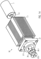
- the motor mount 7.1 is a cuboid-shaped body with cooling fins 7.1.3 arranged on its side surfaces 7.1.2.
- the motor mount 7.1 has a centrally located bore 7.1.4 in the axial direction.
- the motor shaft 7.2 is guided through this bore 7.1.4.
- an axially aligned recess 7.1.5 is provided in which the motor 7 is arranged.
- the motor 7 is, for example, a standard electric motor from Faulhaber with an output of 38 W at 30,000 rpm or another suitable motor.
- a cooling fan is arranged on a side surface 7.1.2 of the cuboid motor mount 7.1.
- a cover tube 29 is arranged over the pump head 3 and a distal region of the proximal catheter shaft.
- the cover tube 29 has an inner diameter that, in the region of the pump head 3, corresponds to the outer diameter of the non-expanded pump housing.
- the outer diameter of the cover tube is approximately 3 mm.
- the ball head bearing holder 22.7 of the coupling element 22 is pressed onto the ball head 24.6 of the cover plate 24, forming the ball head bearing 25.
- the ball head bearing centers the axial run of the drive shaft 4.
- the inner ring magnet 20.1 is radially guided at a constant distance within the outer ring magnet 20.2.
- the magnetic ring bearing 20.3, in conjunction with the ball head bearing 25, centers and guides the rotationally symmetrical running of the coupling element 22 or the drive shaft 4 to prevent impacts or imbalance.
- the motor shaft 7.2 rotates at a speed of approximately 20,000 rpm to 40,000 rpm and preferably approximately 32,000 rpm to 35,000 rpm, which is transmitted to the drive shaft 4.
- the rotor 3.2 delivers a flow rate of approximately 2 l/min to 2.5 l/min at a differential pressure of 60 mm Hg.
- the drive shaft 4 twists or shortens, and the resistance at the distal magnet unit 23.1 increases.
- the magnetic fields between the proximal and distal magnet units 23.2, 23.1 do not completely overlap during operation, since the distal magnet unit 23.1 always lags slightly. If the required torque on the distal magnet unit 23.1 increases, the north and south poles of the magnet units 23.1, 23.2 no longer overlap but repel each other. As a result, the distal magnet unit 23.1 is pushed distally by the proximal magnet unit 23.2. The magnetic connection between the two magnet units 23.1, 23.2 is severed. The drive shaft 4 immediately stops.
- the inner ring magnet 20.2 of the coupling element 22 is also displaced in the distal direction, and the north and south poles of the two ring magnets 20.1, 20.2 of the magnetic ring bearing 20.3 no longer overlap but repel each other. This keeps the coupling 9 in the decoupled state, resulting in a permanent decoupling of the motor 7 and the drive shaft 4.
- This state can be reversed by applying an external magnetic field.
- the two magnet units 23.1, 23.2 can be returned to their coupled initial position.
- the clutch housing 19 and the motor assembly 30 are spatially separated from each other. This makes it possible to drive the drive shaft 4 via the
- the pump located in the flushing bore 19.15 is to be lubricated at approximately 5-10 ml/h despite its high speed in order to minimize friction. It may also be provided to introduce an infusion via the flushing bore 19.15, which also lubricates the drive shaft 4.
- the small diameter of the drive shaft is advantageous at high speeds of approximately 32,000 rpm. Larger diameters would result in excessive peripheral speed, and friction could cause damage to drive shaft 4 or adjacent components.
- the arrangement of the ball-and-socket bearing 25 (plain bearing), the magnetic ring bearing 20.3 (non-contact, damping, and centering), and the axial plain bearing between the drive shaft 4 and the clutch housing 19 results in three stabilization points.
- This allows the drive shaft 4 to transmit torque even during an axial change in length (extension and shortening).
- a change in length occurs, for example, when the pump head 3 is compressed.
- the rotor 3.2 is compressed, folded around the drive shaft, and clamped in the housing.
- the pump housing 3.1 extends proximally.
- the drive shaft 4 can move sufficiently so that it is not torn off the rotor 3.2.
- the displaceability of the drive shaft 4 allows for the length change of the PU catheter shaft due to fluid absorption, temperature differences, and bending of the catheter shaft 8.2, which influence the length ratios between the drive shaft 4 and the catheter shaft 8.2, to be compensated. This mechanism is made possible by the displaceability of the square rod 21 within the axial recess 22.1.
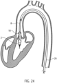
- the pump head 3 is positioned in the left ventricle in such a way that the outflow tube 18 is positioned approximately centrally in the transition from the aorta to the heart, i.e. in the area the heart valve.
- the catheter device 1 is preferably designed such that it can generate a specific pump pressure in the range of approximately 100 mm Hg to 150 mm Hg. If the heart is in systole, the catheter device pumps blood if the pressure built up by the heart is less than the pump pressure. A diseased heart is thus relieved. During diastole, an opposite pressure difference exists. If the pressure difference is greater than the pump pressure, the catheter device cannot pump blood. In this case, the outflow tube is compressed by the heart valve so that it is sealed. If, however, the pressure difference is less than the pump pressure, some blood is pumped against the pressure difference.
- Fig. 24 shows the positioned catheter device 1 for left ventricular assist.
- the pump head 3 is located entirely within the left ventricle.
- the outflow tube extends through the heart valve.
- a cover tube 29 is first guided into the left ventricle using a guidewire (Seldinger technique). The guidewire is then removed from the cover tube.
- the catheter device 1, with the compressed and cooled pump housing 19 and rotor 3.2, is inserted through the cover tube until the catheter device 1 with the pump head 3 reaches the left ventricle. Deployment occurs by retracting the cover tube 29 on the fixed catheter shaft 8 until the tip of the cover tube 29 has released the pump head 3.
- the cover tube 29 is advanced to the shaft cap 10, whereby the rotor 3.2 and pump housing 3.1 are drawn into the cover tube 29 in a compressed state, after which the cover tube is extracted through the puncture site.
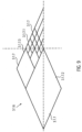
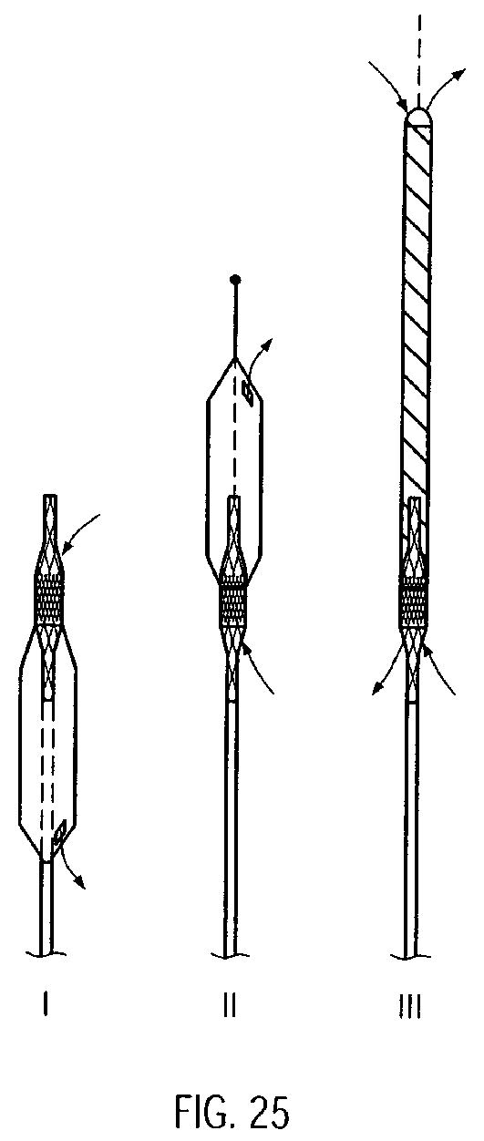
- the present invention is provided to pump a pump medium from proximal to distal, i.e. opposite to the original conveying direction 5 ( Fig. 25 II).
- the distal conveying direction can be realized either by reversing the direction of rotation compared to the above embodiment or by reversing the pitch of the rotor 3.2.
- the outflow hose 18 is arranged at the distal end of the pump section of the pump housing 19 and extends in the distal direction beyond the pump head.
- the outflow hose can have a lattice structure made of a shape memory material, e.g., similar to that of the pump housing.
- the shaft cap 10 extends beyond the distal end of the outflow hose.
- the pump medium flows through the outlet openings of the pump housing, which now serve as inlets, into the pump housing and reaches the outflow tube 18 via the inlet opening of the pump housing, which now serves as outlet.
- the pump medium exits the catheter device 1 via the distal end of the outflow tube.
- the embodiment just described can, for example, be intended for use in the right ventricle.
- the catheter device according to the invention can also be designed in such a way that pumping from distal to proximal and from proximal to distal is possible ( Fig. 25 III).
- bearing discs 15 are provided at the distal and proximal ends of the rotor 3.2.
- the discharge hose 18 is arranged at the distal end of the pump section 3.1.3 of the pump housing 3.1 and extends in the distal direction.
- the discharge hose 18 has a lattice structure for stiffening, e.g., similar to the pump housing.
- the lattice structure is covered with a PU skin.
- the diameter of the discharge hose approximately corresponds to that of the expanded pump housing.
- a pumped medium can enter or exit through the outlet openings of the pump housing.
- the pumped medium then enters, for example, via the outlet openings of the pump housing and the inlet openings of the pump housing into the outflow tube and exits at the distal end of the outflow tube.
- the flow through the catheter device is reversed accordingly.
- the pumped medium enters the outflow tube at the distal end of the outflow tube and flows through the inlet opening of the pump housing to the outlet openings of the pump housing.
- distal or proximal outflow is possible through the pressure- and suction-stabilized outflow tube 18.
- the embodiment just described can be used, for example, for drainage or for filling hollow organs or spaces.
- the reversal of the conveying direction can be achieved on the one hand by reversing the direction of rotation of the rotor and on the other hand by reversing the pitch of the rotor.
- the magnet units each comprise four curved bar magnets, each of which is placed against the other with opposite poles.
- the magnet units can also be designed such that the north and south poles of the magnet units are aligned in the axial direction, with the poles being arranged on the axially distal and proximal surfaces, respectively.
- the magnets are arranged in a ring-shaped manner, as in the previous embodiments.
- Such a coupling can be used, for example, to drive a milling head instead of a rotor.
- a micro-milling machine can be used to mill kidney stones or bones in a minimally invasive manner.
- the number of magnets can basically be varied as desired.
- the rotor after the WO 99/44651 It features an elastic band to connect the ends of a nitinol coil to a rotating shaft. This elastic connection causes the coil to be imperfectly centered. This results in vibrations during pumping, making higher speeds and flow rates impossible.
- the rotor's frame structure makes the rotor more stable, foldable, and expandable to virtually any diameter. Because the rotor can be designed to be virtually any length in the longitudinal direction, the rotor's radial extension is freely selectable. This allows for any desired flow rate, particularly very high flow rates, to be achieved, and it is possible to individually adapt the flow rate for each application.
- the pitch of the rotor can also be varied as desired.
- the rotor can be configured with one or more rotor blades, with the rotor blades wrapping around the drive shaft in a quarter, half, full, or any number of ways. This means that the rotor according to the invention can be varied as desired in terms of its size, shape, and pitch, making it suitable for a wide variety of applications.
Landscapes
- Health & Medical Sciences (AREA)
- Heart & Thoracic Surgery (AREA)
- Engineering & Computer Science (AREA)
- General Health & Medical Sciences (AREA)
- Veterinary Medicine (AREA)
- Anesthesiology (AREA)
- Biomedical Technology (AREA)
- Hematology (AREA)
- Life Sciences & Earth Sciences (AREA)
- Animal Behavior & Ethology (AREA)
- Cardiology (AREA)
- Public Health (AREA)
- Mechanical Engineering (AREA)
- Vascular Medicine (AREA)
- External Artificial Organs (AREA)
- Ultra Sonic Daignosis Equipment (AREA)
- Endoscopes (AREA)
- Eye Examination Apparatus (AREA)
- Non-Portable Lighting Devices Or Systems Thereof (AREA)
- Surgical Instruments (AREA)
Abstract
Die vorliegende Erfindung betrifft eine Katheter-Vorrichtung umfassend einen Pumpenkopf (3) mit einem Rotor (3.2) und eine Antriebswelle (4). Die die Antriebswelle (4) erstreckt sich in der Katheter-Vorrichtung von einem proximalen Ende (6) der Katheter-Vorrichtung (1) bis zu einem distalen Ende (2) der Katheter-Vorrichtung (1). Der Pumpenkopf (3) ist an dem distalen Ende (2) der Katheter-Vorrichtung (1) angeordnet. Die Antriebswelle (4) ist zum Antreiben des Rotors (3.2) an dem distalen Ende (2) der Katheter-Vorrichtung (1) mit dem Rotor (3.2) verbunden und an dem proximalen Ende (6) der Katheter-Vorrichtung (1) mittels einer Kupplung (9) mit einem Motor (7) verbindbar, insbesondere mit dem Motor (7) verbunden. Der Pumpenkopf (3) weist ein Pumpengehäuse (3.1) auf, wobei in einem Pumpenabschnitt (3.1.3) des Pumpengehäuses (3.1) ein Rotor (3.2) aufgenommen ist und das Pumpengehäuse (3.1) distal des Pumpenabschnitts (3.1.3) distale Einlassöffnungen und proximal des Pumpenabschnitts (3.1.3) proximale Auslassöffnungen aufweist. Distal des Pumpenabschnitts (3.1.3) ist ein sogstabilisierter Schlauch angeordnet und derart mit dem Pumpengehäuse (3.1) verbunden, dass im Betrieb des Rotors durch den Schlauch Pumpmedium angesaugt wird und durch die distalen Einlassöffnungen in den Pumpenabschnitt (3.1.3) eintritt.
Description
Die Erfindung betrifft eine Katheter-Vorrichtung, insbesondere eine Katheter-Vorrichtung mit einer langgestreckten Antriebswelle.The invention relates to a catheter device, in particular a catheter device with an elongated drive shaft.
Für die Behandlung schwer herzkranker Patienten werden zunehmend implantierbare Blutpumpen eingesetzt. Derartige Blutpumpen sind bisher vorwiegend für den langfristigen Einsatz vorgesehen. Es werden aber auch Blutpumpen entwickelt, die für die kurzfristige Herzunterstützung ausgelegt sind und minimal-invasiv eingesetzt werden können. Medizinische Ziele sind dabei die Entlastung und Gesundung des Herzens oder aber die Überbrückung bis zu einer möglichen Herztransplantation. Die Breite des Einsatzgebietes solcher Pumpen hängt einerseits von der Einfachheit der Einbringung in den Körper, andererseits von den realisierbaren technischen Eigenschaften und insbesondere der zuverlässig realisierbaren Betriebsdauer der verfügbaren Pumpensysteme ab. Idealerweise sollte eine solche Blutpumpe für die Kurzfristbehandlung perkutan-intravasal ohne jeglichen chirurgischen Eingriff einsetzbar sein.Implantable blood pumps are increasingly being used to treat patients with severe heart disease. Such blood pumps have so far been primarily intended for long-term use. However, blood pumps designed for short-term cardiac support and minimally invasive use are also being developed. The medical goals here are to relieve the strain on the heart and restore it to health, or to bridge the gap until a possible heart transplant. The range of applications for such pumps depends on the ease of insertion into the body, as well as on the achievable technical properties and, in particular, the reliably achievable operating life of the available pump systems. Ideally, such a blood pump should be suitable for percutaneous-intravascular use for short-term treatment without any surgical intervention.
Im kardiogenen Schock ist die Auswurfleistung des linken Ventrikels erheblich reduziert. Die verminderte Koronarversorgung kann zum irreversiblen Herzversagen führen. Durch den Einsatz eines temporären linksventrikulären Unterstützungssystems soll die Pumpfunktion des linken Ventrikels teilweise bzw. weitgehend übernommen und die Koronarversorgung verbessert werden. Bei Herzoperationen kann ein solches System links- und rechtsventrikulär eingesetzt werden und eine Herz-Lungenmaschine ersetzen.In cardiogenic shock, the left ventricular ejection capacity is significantly reduced. The reduced coronary artery supply can lead to irreversible heart failure. The use of a temporary left ventricular assist device is intended to partially or largely take over the pumping function of the left ventricle. and improve coronary artery supply. In cardiac surgery, such a system can be used in both the left and right ventricle and replace a heart-lung machine.
Ein perkutan-intravsal implantierbares System, das bisher klinische Bedeutung erlangt hat, ist die intraaortale Ballonpumpe (IABP). Die Intraaortale Ballonpumpe oder intraaortale Gegenpulsation ist ein mechanisches System, das auch zur Unterstützung der Pumpleistung des Herzens bei Patienten mit einem kardiogenen Schock eingesetzt wird. Dabei wird ein Katheter mit einem zylindrisch geformten Kunststoffballon über die Leiste in die Brustschlagader (Aorta thoracalis) vorgeschoben, so dass der Ballon unterhalb des Abgangs der linken Schlüsselbeinarterie (Arteria subclavia sinistra) liegt. Dort wird der Ballon mit einer externen Pumpe rhythmisch mit jeder Herzaktion in der Diastole mit 30-40 cm3 Helium aufgeblasen und in der Systole wieder abgelassen. Auf diese Weise verbessert die Ballonpumpe die Durchblutung des Herzmuskels und auch die aller anderen Organe. Die erzielbare hämodynamische Verbesserung ist jedoch nur sehr begrenzt, da aufgrund des Konstruktionsprinzips der IABP keine aktive Blutförderung stattfindet. Durch eine Gegenpulsation wird lediglich im Rhythmus des Herzschlags die Aorta unterhalb des linken Ventrikels verschlossen und somit das vom Herzen noch ausgeworfene Blut zurückgedrückt und umverteilt, damit auch in die Koronarien. Eine Steigerung des Blutflusses erfolgt nicht.One percutaneous-intravascular implantable system that has achieved clinical significance to date is the intra-aortic balloon pump (IABP). The intra-aortic balloon pump, or intra-aortic counterpulsation, is a mechanical system that is also used to support the heart's pumping performance in patients with cardiogenic shock. A catheter containing a cylindrical plastic balloon is advanced via the groin into the thoracic aorta, so that the balloon lies below the origin of the left subclavian artery. There, an external pump rhythmically inflates the balloon with 30–40 cm³ of helium with each heartbeat during diastole and deflates it again during systole. In this way, the balloon pump improves blood flow to the heart muscle and all other organs. However, the achievable hemodynamic improvement is very limited because, due to the design principle of the IABP, no active blood flow occurs. Counterpulsation simply closes the aorta below the left ventricle in rhythm with the heartbeat, pushing back and redistributing the blood still ejected by the heart, including into the coronary arteries. There is no increase in blood flow.
Eine bekannte transfemoral implantierbare Mikro-Axialpumpe "Hemopump™"der Firma Medtronic Inc, USA, stellt sich nach experimenteller und vorläufiger klinischer Prüfung als erfolgsversprechendes Konzept dar, welches eine ausreichende Linksherzentlastung bewirken kann. Der Ansaugstutzen der Pumpe wird retrograd über die Aortenklappe im linken Ventrikel platziert. Der Pumpenrotor befindet sich am Ende einer Kanüle in der oberen Aorta descendens und wird durch einen externen Motor angetrieben. Nachteil des Systems ist, dass die transfemorale Implantation aufgrund des großen Durchmessers des Rotors nur operativ über eine femorale Arterietomie und gegebenenfalls durch eine Graftankopplung möglich ist.A well-known transfemoral implantable micro-axial pump, the "Hemopump ™ " from Medtronic Inc., USA, has been shown, after experimental and preliminary clinical trials, to be a promising concept that can provide sufficient left ventricular relief. The pump's intake port is placed retrogradely over the aortic valve in the left ventricle. The pump rotor is located at the end of a cannula in the superior descending aorta and is driven by an external motor. The disadvantage of this system is that, due to the rotor's large diameter, transfemoral implantation is only possible surgically via a femoral artery graft and, if necessary, by grafting.
Aus der
In der
Aus der
In der
In der
Der vorliegenden Erfindung liegt die Aufgabe zugrunde, eine Katheter-Vorrichtung mit einer sich fast über die gesamte Katheter-Vorrichtung erstreckenden Antriebswelle zu schaffen, die zuverlässig mit hoher Drehzahl angetrieben werden kann.The present invention is based on the object of creating a catheter device with a drive shaft extending almost over the entire catheter device, which can be reliably driven at high speed.
Die Aufgabe wird mit einer Katheter-Vorrichtung gemäß Anspruch 1 gelöst. Vorteilhafte Ausgestaltungen der Erfindung sind in den Unteransprüchen angegeben.The object is achieved with a catheter device according to claim 1. Advantageous embodiments of the invention are specified in the subclaims.
Die Katheter-Vorrichtung umfasst einen am proximalen Ende der Katheter-Vorrichtung befindlichen Motor und eine sich vom proximalen Endbereich der Katheter-Vorrichtung bis zum distalen Endbereich erstreckende Antriebswelle zum Antreiben eines sich am distalen Ende der Katheter-Vorrichtung befindlichen drehenden Elements. Die Antriebswelle ist am proximalen Ende der Katheter-Vorrichtung mittels einer Kupplung mit dem Motor verbunden. Die Kupplung ist eine Magnetkupplung mit einer proximalen und einer distalen Magneteinheit. Die proximale Magneteinheit ist mit dem Motor verbunden und die distale Magneteinheit mit der Antriebswelle. Die distale Magneteinheit ist in einem Kupplungsgehäuse gelagert und durch eine Wandung räumlich getrennt von der proximalen Magneteinheit angeordnet.The catheter device comprises a motor located at the proximal end of the catheter device and a drive shaft extending from the proximal end of the catheter device to the distal end for driving a rotating element located at the distal end of the catheter device. The drive shaft is connected to the motor at the proximal end of the catheter device by means of a coupling. The coupling is a magnetic coupling with a proximal and a distal magnet unit. The proximal magnet unit is connected to the motor, and the distal magnet unit is connected to the drive shaft. The distal magnet unit is mounted in a coupling housing and is spatially separated from the proximal magnet unit by a wall.
Durch die Trennung der abtriebsseitigen Kupplungselemente bis hin zum distalen Ende der Katheter-Vorrichtung ist es nicht notwendig, die Antriebswelle nach außen durch ein Loch zu führen. Eine solche Durchführung müsste abgedichtet werden. Eine solche Abdichtung begrenzt jedoch die Drehzahl. Da bei dieser Katheter-Vorrichtung keine entsprechende Abdichtung einer Antriebswellendurchführung vorhanden ist, können sehr hohe Drehzahlen auf die Antriebswelle übertragen werden.By separating the output-side coupling elements up to the distal end of the catheter device, it is not necessary to extend the drive shaft outwards through a hole. Such a passage would have to be sealed. However, such a seal limits the rotational speed. Since this catheter device does not have a corresponding seal for the drive shaft passage, very high rotational speeds can be transmitted to the drive shaft.
Durch das Magnetringlager bzw. die magnetische Verbindung der beiden Magneteinheiten wird der Beitrag des übertragbaren Drehmoments begrenzt. Sobald das einstellbare Drehmoment überschritten wird, trennen sich die beiden Magneteinheiten.The magnetic ring bearing, or rather the magnetic connection between the two magnet units, limits the contribution of the transmittable torque. As soon as the adjustable torque is exceeded, the two magnet units separate.
Vorzugsweise umfasst die Katheter-Vorrichtung einen schlauchförmigen Katheterschaft, der die Antriebswelle umschließt und sich vom proximalen Endbereich bis zum distalen Endbereich der Katheter-Vorrichtung erstreckt. Der Katheterschaft ist mit seinem proximalen Ende flüssigkeitsdicht mit dem Kupplungsgehäuse verbunden.Preferably, the catheter device comprises a tubular catheter shaft that surrounds the drive shaft and extends from the proximal end region to the distal end region of the catheter device. The catheter shaft is connected to the coupling housing at its proximal end in a fluid-tight manner.
Über eine Spülbohrung im Kupplungsgehäuse ist das Einbringen eines Spülmediums zum Schmieren der Antriebswelle und der abtriebseitigen Kupplungselemente möglich. Hierdurch wird verhindert, dass Blut in den Bereich zwischen der Antriebswelle und dem Katheterschaft eindringt und die Drehbarkeit der Antriebswelle beeinträchtigt.A flushing hole in the coupling housing allows the introduction of a flushing medium to lubricate the drive shaft and the output-side coupling elements. This prevents blood from penetrating the area between the drive shaft and the catheter shaft and impairing the rotation of the drive shaft.
Vorzugsweise ist ein die distale Magneteinheit tragendes abtriebsseitiges Kupplungselement mittels eines Gleitlagers gelagert. Hierdurch kann präzise der Abstand zwischen den beiden Magneteinheiten festgelegt werden.Preferably, a coupling element on the output side supporting the distal magnet unit is supported by a plain bearing. This allows the distance between the two magnet units to be precisely determined.
Gemäß einer Weiterbildung ist ein zusätzliches Magnetringlager vorgesehen, das zum einen eine weitere vor allem radiale Lagerung des abtriebsseitigen Kupplungselements bewirkt und zum anderen den durch die Magneteinheiten ausgeübten Kräften entgegenwirken kann, so dass die Kraft mit welcher das abtriebsseitige Kupplungselement gegen das Gleitlager gedrückt wird, vermindert wird.According to a further development, an additional magnetic ring bearing is provided which, on the one hand, provides further, primarily radial, support for the output-side coupling element and, on the other hand, can counteract the forces exerted by the magnet units, so that the force with which the output-side coupling element is pressed against the plain bearing is reduced.
Sowohl durch den durch das Gleitlager festgelegten Abstand zwischen den beiden Magneteinheiten als auch durch die Kraft, mit welcher das Kupplungselement durch das Magnetringlager in Axialrichtung beaufschlagt wird, wird das mit der Magnetkupplung maximal übertragbare Drehmoment eingestellt.The maximum torque that can be transmitted by the magnetic coupling is set both by the distance between the two magnetic units determined by the plain bearing and by the force with which the coupling element is subjected in the axial direction by the magnetic ring bearing.
Der Durchmesser der Antriebswelle kann im Bereich von 0,3 mm bis 1 mm liegen und beträgt vorzugsweise etwa 0,4 mm bis 0,6 mm. Je kleiner der Durchmesser der Antriebswelle ist, desto größer kann die Drehgeschwindigkeit, mit der die Antriebswelle vom Motor angetrieben wird, sein.The diameter of the drive shaft can range from 0.3 mm to 1 mm, and is preferably approximately 0.4 mm to 0.6 mm. The smaller the diameter of the drive shaft, the higher the rotational speed at which the drive shaft is driven by the motor can be.
Das mittels der Antriebswelle sich drehende Element kann ein Rotor, ein Fräswerkzeug oder ein sonstiges Werkzeug sein.The element rotating by means of the drive shaft can be a rotor, a milling tool or another tool.
Ein solcher Rotor ist vorzugsweise selbstentfaltend ausgebildet. Er kann mit einem Pumpengehäuse versehen sein, das wie der Rotor auf einen geringen Durchmesser komprimierbar ist. Der Rotor und das Pumpengehäuse sind gemäß einem bevorzugtem Ausführungsbeispiel aus einem Formgedächtnismaterial ausgebildet.Such a rotor is preferably designed to be self-expanding. It can be provided with a pump housing that, like the rotor, can be compressed to a small diameter. According to a preferred embodiment, the rotor and the pump housing are made of a shape-memory material.
Die Kombination eines solchen selbstentfaltbaren Pumpenkopfes mit der oben erläuterten Magnetkupplung bildet eine Katheter-Vorrichtung, mit der einerseits aufgrund der hohen Drehzahl und des großen Rotors eine hohe Pumpleistung erzielt wird, und mit der andererseits eine hohe Lebensdauer von einigen Stunden bis hin zu einigen Tagen erzielt wird.The combination of such a self-deploying pump head with the magnetic coupling described above forms a catheter device which, on the one hand, achieves a high pumping performance due to the high speed and the large rotor, and on the other hand, achieves a long service life of several hours to several days.
Die Erfindung wird im folgenden anhand der Zeichnungen beispielhaft näher erläutert. Diese zeigen schematisch in:
- Fig. 1
- ein perspektivische Darstellung einer erfindungsgemäßen Katheter-Vorrichtung,
- Fig. 2
- eine Explosionszeichnungen einer erfindungsgemäßen Katheter-Vorrichtung ,
- Fig. 3
- eine Schaftkappe der Katheter-Vorrichtung in einer seitlich geschnittenen Ansicht,
- Fig. 4
- ein distales Katheterschaftstück der Katheter-Vorrichtung in einer seitlich geschnittenen Ansicht,
- Fig. 5
- eine Verbindungsbuchse der Katheter-Vorrichtung in einer seitlich geschnittenen Ansicht,
- Fig. 6
- eine Pumpe der Katheter-Vorrichtung mit Lagerung in einer seitlich geschnittenen Ansicht,
- Fig. 7a
- einen Schnitt entlang der Linie A-A durch die distale Verbindungsbuchse der Katheter-Vorrichtung,
- Fig. 7b
- einen Schnitt entlang der Linie B-B durch die proximale Verbindungsbuchse der Katheter-Vorrichtung,
- Fig. 8
- eine Gitterstruktur eines Pumpengehäuses der Katheter-Vorrichtung,
- Fig. 9
- einen Ausschnitt der Gitterstruktur des Pumpengehäuses der Katheter-Vorrichtung,
- Fig. 10
- eine Antriebswelle mit Führungsspirale und Wellenschutz der Katheter-Vorrichtung,
- Fig. 11a
- eine Rahmenstruktur eines Rotors einer Pumpe der Katheter-Vorrichtung,
- Fig. 11b
- eine weitere Rahmenstruktur des Rotors der Pumpe der Katheter-Vorrichtung,
- Fig. 12
- den erfindungsgemäßen Rotor der Pumpe der Katheter-Vorrichtung in einer perspektivischen Ansicht,
- Fig. 13
- einen Abströmschlauch der Katheter-Vorrichtung in einer perspektivischen Ansicht,
- Fig. 14
- eine erfindungsgemäße Kupplung mit Kupplungsgehäuse und Motor der Katheter-Vorrichtung in einer perspektivischen Ansicht,
- Fig. 15
- die erfindungsgemäße Kupplung mit dem Kupplungsgehäuse der Katheter-Vorrichtung in einer perspektivischen Ansicht,
- Fig. 16
- das Kupplungsgehäuse der Katheter-Vorrichtung in einer perspektivischen Ansicht,
- Fig. 17
- eine Vierkantstange der Kupplung der Katheter-Vorrichtung in einer seitlichen Ansicht,
- Fig. 18
- ein Kupplungselement der Kupplung der Katheter-Vorrichtung in einer seitlichen Ansicht,
- Fig. 19
- eine Abschlussscheibe der Kupplung der Katheter-Vorrichtung in einer seitlichen Ansicht,
- Fig. 20
- eine Kugelkopflagerkugel der Kupplung der Katheter-Vorrichtung in einer seitlichen Ansicht,
- Fig. 21
- einen Zentrierstift der Kupplung der Katheter-Vorrichtung in einer seitlichen Ansicht,
- Fig. 22
- eine Motoraufnahme der Katheter-Vorrichtung in einer seitlichen Ansicht,
- Fig. 23
- das Kupplungselement mit der darin angeordneten Vierkantstange in einer Draufsicht,
- Fig. 24
- die im Körper positionierte Katheter-Vorrichtung, und
- Fig. 25
- schematisch alternative Ausführungsformen der Katheter-Vorrichtung.
- Fig. 1
- a perspective view of a catheter device according to the invention,
- Fig. 2
- an exploded view of a catheter device according to the invention,
- Fig. 3
- a shaft cap of the catheter device in a side section view,
- Fig. 4
- a distal catheter shaft piece of the catheter device in a side section view,
- Fig. 5
- a connecting socket of the catheter device in a side section view,
- Fig. 6
- a pump of the catheter device with bearing in a side section view,
- Fig. 7a
- a section along the line AA through the distal connection socket of the catheter device,
- Fig. 7b
- a section along the line BB through the proximal connection socket of the catheter device,
- Fig. 8
- a lattice structure of a pump housing of the catheter device,
- Fig. 9
- a section of the lattice structure of the pump housing of the catheter device,
- Fig. 10
- a drive shaft with guide spiral and shaft protection of the catheter device,
- Fig. 11a
- a frame structure of a rotor of a pump of the catheter device,
- Fig. 11b
- another frame structure of the rotor of the pump of the catheter device,
- Fig. 12
- the rotor of the pump of the catheter device according to the invention in a perspective view,
- Fig. 13
- an outflow tube of the catheter device in a perspective view,
- Fig. 14
- a coupling according to the invention with coupling housing and motor of the catheter device in a perspective view,
- Fig. 15
- the coupling according to the invention with the coupling housing of the catheter device in a perspective view,
- Fig. 16
- the coupling housing of the catheter device in a perspective view,
- Fig. 17
- a square rod of the coupling of the catheter device in a side view,
- Fig. 18
- a coupling element of the coupling of the catheter device in a side view,
- Fig. 19
- a cover plate of the coupling of the catheter device in a side view,
- Fig. 20
- a ball head bearing ball of the coupling of the catheter device in a side view,
- Fig. 21
- a centering pin of the coupling of the catheter device in a side view,
- Fig. 22
- a motor mount of the catheter device in a side view,
- Fig. 23
- the coupling element with the square bar arranged therein in a plan view,
- Fig. 24
- the catheter device positioned in the body, and
- Fig. 25
- schematically alternative embodiments of the catheter device.
Der Pumpenkopf 3 weist einen Rotor 3.2 zum Fördern eines Mediums in Förderrichtung 5 auf, der mit einer Antriebswelle 4 verbunden ist. Die Förderrichtung 5 ist vom distalen Ende 2 zu einem proximalen Ende 6 gerichtet. An dem vom Pumpenkopf 3 beabstandeten proximalen Ende 6 ist ein Motor 7 angeordnet. Die Antriebswelle 4 ist von einem Katheterschaft 8 umgeben und mittels einer Kupplung 9 kraftschlüssig mit dem Motor 7 verbunden.The
Nachfolgend wird zunächst der Pumpenkopf 3 näher erläutert. Der Pumpenkopf 3 umfasst eine Schaftkappe 10 am distalen Ende, den auf der Antriebswelle 4 angeordneten Rotor 3.2, ein Pumpengehäuse 3.1 und einen Abströmschlauch 18.The
Die Schaftkappe 10 ist aus einer Kugel 10.1 mit einem angesetzten zylinderförmigen Abschnitt 10.2 ausgebildet. Die Schaftkappe 10 ist beispielsweise aus Edelstahl ausgebildet (
Der Durchmesser der Kugel 10.1 beträgt in etwa 3.2 mm. Der zylinderförmige Abschnitt 10.2 ist in etwa 5,5 mm lang und hat einen Durchmesser von in etwa 2,2 mm. Die Gesamtlänge der Schaftkappe beträgt in etwa 7,0 mm.The diameter of the ball 10.1 is approximately 3.2 mm. The cylindrical section 10.2 is approximately 5.5 mm long and has a diameter of approximately 2.2 mm. The total length of the butt plate is approximately 7.0 mm.
Der zylinderförmige Abschnitt 10.2 weist an seinem distalen Ende, im Anschlussbereich zur Kugel 10.1 eine quer zur Förderrichtung 5 angeordnete Durchgangsbohrung 10.3 auf. Weiterhin weist der Zylinder 10.2 eine axiale Bohrung 10.4 auf, die sich vom proximalen Ende des zylinderförmigen Abschnittes 10.2 bis zur Kugel 10.1 hin erstreckt, so dass ein kommunizierender Durchgang von der Durchgangsbohrung 10.3 bis zum proximalen Ende der Schaftkappe 10 ausgebildet ist. Im Bereich der axialen Bohrung 10.4 ist eine Stufe 10.5 ausgebildet, so dass die axiale Bohrung in Richtung des proximalen Endes aufgeweitet ist.The cylindrical section 10.2 has, at its distal end, in the connection area to the ball 10.1, a through-bore 10.3 arranged transversely to the conveying
Durch die Durchgangsbohrung 10.3 wird einerseits vermieden, dass in der Schaftkappe ein Sackloch entsteht und andererseits erlaubt das Durchgangsloch die Anbringung eines Fadens, der beim Komprimieren des Pumpenkopfes 3 hilfreich ist.The through hole 10.3 prevents the formation of a blind hole in the shaft cap and also allows the attachment of a thread which is helpful when compressing the
Anstelle der Kugel 10.1 der Schaftkappe 10 kann auch ein Pigtail, eine Spirale, ein mäanderförmiger Draht mit Kugelspitze oder ein atraumatisches Faserbündel vorgesehen sein. Die Schaftkappe ist aufgrund ihrer geringen Größe bevorzugt.Instead of the ball 10.1 of the
Die Spitze der Schaftkappe 10 ist eine atraumatische Kugel zum Schutz des Herzmuskels (Endocard). Über die Schaftkappe 10 kann der Pumpenkopf 3 an der Herzwand abgestützt werden.The tip of the
Ein rohrförmiges bzw. schlauchförmiges, distales Katheterschaftstück 8.1 ist vom proximalen Ende in die Schaftkappe 10 bis zur Stufe eingeführt. Das distale Katheterschaftstück 8.1 wird in der axialen Bohrung 10.4 passgenau aufgenommen und ist dort fixiert (
Das distale Katheterschaftstück 8.1 bildet eine gerade, aber leicht flexible Verbindung zwischen der Schaftkappe 10 und dem Pumpengehäuse 3.1. Die gerade Verbindung stellt eine Koaxialität aller in ihr angeordneten Bauteile (Antriebswelle, Wellenschutz, Gehäuse, Verbindungsbuchse) her.The distal catheter shaft piece 8.1 forms a straight, yet slightly flexible connection between the
Das distale Katheterschaftstück 8.1 dient in Verbindung mit der Schaftkappe 10 als Positionierungshilfe des Pumpenkopfes 3 beim Einbringen in ein Gefäß bzw. das Herz.The distal catheter shaft piece 8.1, in conjunction with the
Das Katheterschaftstück 8.1 im vorliegenden Ausführungsbeispiel weist eine Länge von in etwa 25 mm, einen Außendurchmesser von in etwa 1,9 mm und einen Innendurchmesser von in etwa 1,3 mm auf.The catheter shaft piece 8.1 in the present embodiment has a length of approximately 25 mm, an outer diameter of approximately 1.9 mm and an inner diameter of approximately 1.3 mm.
Am proximalen Ende des distalen Katheterschaftstücks 8.1 ist eine distale, röhrenförmige Verbindungsbuchse 12.1 vorgesehen (
Die distale Verbindungsbuchse 12.1 weist eine Länge von in etwa 5 mm und einen Außendurchmesser von in etwa 2,2 mm auf. Im distalen Bereich beträgt der Durchmesser in etwa 2 mm und im proximalen Bereich in etwa 1,5 mm. Je kürzer die Verbindungsbuchse ist, desto geringer ist die hierdurch bewirkte Aussteifung.The distal connecting bushing 12.1 has a length of approximately 5 mm and an outer diameter of approximately 2.2 mm. The diameter in the distal region is approximately 2 mm and in the proximal region approximately 1.5 mm. The shorter the connecting bushing, the less stiffening it provides.
Die distale und eine analog ausgebildete proximale Verbindungsbuchse 12.1, 12.2 sind beispielsweise aus Edelstahl, Kupfer, Messing, Titan oder einem anderen geeigneten Metall, aus Polyethylen (PE), Polypropylen (PP), Teflon (PTFE), PEBAX, einem Polyether-Block-Amid, oder einem anderen geeigneten Material ausgebildet.The distal and an analogously designed proximal connecting bushing 12.1, 12.2 are made, for example, of stainless steel, copper, brass, titanium or another suitable metal, of polyethylene (PE), polypropylene (PP), Teflon (PTFE), PEBAX, a polyether block amide, or another suitable material.
Das expandierbare bzw. komprimierbare Pumpengehäuse 3.1 ist eine rohrförmig ausgebildete Gitterstruktur 3.1.6 aus Nitinol oder einer anderen geeigneten Gedächtnislegierung oder einem anderen Formgedächtnismaterial, z.B. Kunststoff, Eisenlegierung, Kupferlegierung. Das Pumpengehäuse 3.1 ist von distal nach proximal in fünf Abschnitte unterteilt (
Die Gitterstruktur 3.1.6 des Pumpengehäuses 3.1 weist zwischen den Gitterstreben Öffnungen 3.1.7 auf (
Im Ansaugabschnitt 3.1.2 und im Auslassabschnitt 3.1.4 sind große Rauten 3.1.7.2 vorgesehen, die in etwa die vierfache Kantenlänge der kleinen Rauten 3.1.7.1 aufweisen. In den Übergangsbereichen vom Ansaugabschnitt 3.1.2 und vom Auslassabschnitt 3.1.4 zum distalen und zum proximalen Verbindungsabschnitt 3.8.1, 3.1.5 der rohrförmigen Gitterstruktur 3.1.6 sind die großen Rauten 3.1.7.2 zu kleiner werdenden Rauten zusammengefasst. Im distalen und im proximalen Verbindungsabschnitt sind mittelgroße Rauten 3.1.7.3 vorgesehen, die in etwa die zweifache Kantenlänge der kleinen Rauten 3.1.7.1 aufweisen (
Die Gitterstruktur 3.1.6 des Pumpengehäuses 3.1 ist im Pumpenabschnitt 3.1.3 mit einer PU-Bespannung 3.1.8 bespannt, wodurch die Gitteröffnungen flüssigkeitsdicht verschlossen sind.The grid structure 3.1.6 of the pump housing 3.1 is covered with a PU covering 3.1.8 in the pump section 3.1.3, whereby the grid openings are sealed liquid-tight.
Diese Bespannung bzw. die Abdichtung der Gitterstruktur 3.1.6 kann auch z.B. durch einen PU-Schlauch der auf der Oberfläche außen oder innen angeordnet ist, ausgebildet sein.This covering or the sealing of the grid structure 3.1.6 can also be formed, for example, by a PU hose arranged on the outside or inside of the surface.
Es kann auch eine andere Bespannung als PU verwendet werden, wie z.B. PE, PP, Silikon oder Parylene, solange sie die mechanischen und geometrischen Anforderungen erfüllt.A covering other than PU can also be used, such as PE, PP, silicone or parylene, as long as it meets the mechanical and geometric requirements.
Durch die Auswahl einzelner Öffnungen 3.1.71, insbesondere der mittleren und größeren Öffnungen 3.1.7.3, 3.1.7.2, die nicht beschichtet werden, können die Leistungsparameter inkl. Blutschädigung der Pumpe gezielt gesteuert werden.By selecting individual openings 3.1.71, especially the medium and larger openings 3.1.7.3, 3.1.7.2, which are not coated, the performance parameters of the pump, including blood damage, can be specifically controlled.
Durch die polygonale Struktur und die besondere Ausführung der PU-Bespannung ergibt sich eine annähernd runde Querschnittsform für das Pumpengehäuse 3.1. In Verbindung mit dem runden Rotor 3.2 ergeben sich dadurch sehr geringe Spalte zwischen Rotor 3.2 und Pumpengehäuse 3.1. Dies führt zu vergleichsweise niedriger Blutschädigung, niedrigen Leckströmen und einem guten Wirkungsgrad. Durch die Gitterstruktur 3.1.6 ergibt sich eine sehr gute radiale und axiale Stabilität sowie eine sehr gute axiale Komprimierbarkeit und Expandierbarkeit. Durch die spezielle Struktur kann sehr einfach eine Anpassung von Länge und Durchmesser an die Leistungsanforderungen erfolgen.The polygonal structure and the special design of the PU covering result in an almost round cross-sectional shape for the pump housing 3.1. In conjunction with the round rotor 3.2, this results in very small gaps between the rotor 3.2 and the pump housing 3.1. This leads to comparatively low Blood damage, low leakage currents, and good efficiency. The 3.1.6 lattice structure results in very good radial and axial stability, as well as excellent axial compressibility and expandability. The special structure allows for easy adjustment of length and diameter to meet performance requirements.
Der proximale Verbindungsabschnitt 3.1.5 des Pumpengehäuses 3.1 ist in der proximalen Verbindungsbuchse 12.2 aufgenommen und mit dieser verbunden. In der proximalen Verbindungsbuchse 12.2 ist analog zur distalen Verbindungsbuchse 12.1 ein schlauchförmiges proximales Katheterschaftstück 8.2 aufgenommen und mit dieser verbunden (
Innerhalb des distalen und des proximalen Katheterschaftstückes 8.1, 8.2 ist in axialer Richtung ein distaler Wellenschutz 13.1 und ein proximaler Wellenschutz 13.2 angeordnet (
Der distale Wellenschutz 13.1 erstreckt sich in Förderichtung 5 von kurz vor der distalen Verbindungsbuchse 12.1 bis zum distalen Ende des Pumpenabschnitts 3.1.3 des Pumpengehäuses 3.1, d.h. bis zum Rotor 3.2. Der proximale Wellenschutz 13.2 erstreckt sich vom proximalen Ende des Rotors 3.2 bis kurz hinter das proximale Ende der proximalen Verbindungsbuchse 12.1.The distal shaft guard 13.1 extends in the
Der distale und der proximale Wellenschutz 13.1, 13.2 sind in den beiden Bereichen, in denen sie innerhalb der distalen und der proximalen Verbindungsbuchse 12.1, 12.2 bzw. des distalen und des proximalen Katheterschaftstücks 8.1, 8.2 angeordnet sind, mit diesen verbunden.The distal and proximal shaft protectors 13.1, 13.2 are connected to the distal and proximal connecting sleeves 12.1, 12.2 and the distal and proximal catheter shaft pieces 8.1, 8.2 in the two areas in which they are arranged within these.
Die beiden Verbindungsbuchsen 12.1, 12.2 bilden zusammen mit den darin angeordneten Bauteilen (Wellenschutz, Pumpengehäuse, Katheterschaft) einen Lagerbereich für die Antriebswelle 4. Die Verbindungsbuchsen 12.1, 12.2 gewährleisten die Achszentriertheit der Antriebswelle 4 insbesondere im Pumpengehäuse 3.1.The two connecting bushings 12.1, 12.2 together with the components arranged therein (shaft protection, pump housing, catheter shaft) form a bearing area for the
Innerhalb des distalen und des proximalen Wellenschutzes 13.1, 13.2 bzw. des Pumpengehäuses 3.1 ist in axialer Richtung die Antriebswelle 4 angeordnet. Die Antriebswelle 4 weist in Förderichtung 5 drei Abschnitte auf. Einen distalen Abschnitt der Antriebswelle 4.1 im Bereich der Schaftkappe 10. Einen Pumpenabschnitt der Antriebswelle 4.2, auf dem der Rotor 3.2 drehfest angeordnet ist und einen proximalen Abschnitt der Antriebswelle 4.3, der sich vom Pumpenabschnitt 3.1.3 bis hin zur Kupplung 9 erstreckt. Der Rotor 3.2. ist mit der Antriebswelle verklebt. Es können jedoch auch andere kraftschlüssige Verbindungen wie Schweißen oder Klemmen vorgesehen sein.The
Der proximale Wellenschutz 13.1 (
Die Antriebswelle 4 ist bevorzugt aus mehreren, insbesondere sechs Drähten (nicht dargestellt), die links- oder rechtsgewickelt um eine Seele (nicht dargestellt) angeordnet sind, ausgebildet. Der Außendurchmesser der Antriebswelle 4 beträgt in etwa 0,48 mm. Die Antriebswelle 4 kann aber auch eine andere Anzahl von Seelen und Drähten aufweisen und einen kleineren oder einen größeren Durchmesser aufweisen. Der Durchmesser der Antriebswelle kann im Bereich von 0,3 mm bis 1 mm liegen und beträgt vorzugsweise etwa 0,4 mm bis 0,6 mm. Je kleiner der Durchmesser der Antriebswelle ist, desto größer kann die Drehgeschwindigkeit sein, denn je kleiner der Durchmesser ist, desto geringer ist die Geschwindigkeit, mit der sich der Umfang der Antriebswelle gegenüber seiner Umgebung bewegt. Eine hohe Umfangsgeschwindigkeit ist problematisch, wenn die Antriebswelle mit der Umgebung in Berührung kommt. Die Katheter-Vorrichtung ist für Drehzahlen von mehr als 20.000 U/min und bis zu 40.000 U/min ausgelegt. Daher wird der Durchmesser der Antriebswelle 4 so gering wie möglich ausgebildet, aber so dick, dass sie noch eine ausreichende Festigkeit besitzt.The
Entgegen der Wickelrichtung der Antriebswelle 4 - im vorliegenden Ausführungsbeispiel ist sie links gewickelt - ist in axialer Richtung um den distalen und den proximalen Abschnitt der Antriebswelle 4.1, 4.3 ein entgegengesetzt gewickelte (hier: rechtsdrehend), spiralförmig ausgebildete Führungsspirale 14 angeordnet, um die Reibung der Antriebswelle 4 zu minimieren, den Wandkontakt der Antriebswelle 4 mit dem proximalen Katheterschaftstück 8.2 zu vermeiden sowie ein Abknicken der Antriebswelle 4 in Folge von Biegung zu verhindern. Durch die Führungsspirale 14 wird die Antriebswelle 4 geführt und geschient bzw. stabilisiert (
Die Antriebswelle 4 erstreckt sich vom distalen Ende des distalen Wellenschutzes 13.1 in Förderrichtung 5 hinter der distalen Verbindungsbuchse 12.1 bis hin zur Kupplung 9.The
Das proximale Katheterschaftstück 8.2 stellt in Verbindung mit der Führungsspirale 14 eine längen- und verwindungskonstante Verbindung zwischen dem Pumpenkopf 3 und der Kupplung 9 bereit.The proximal catheter shaft piece 8.2, in conjunction with the
Am proximalen Ende des distalen Wellenschutzes 13.1 ist eine Lagerscheibe 15 angeordnet (
Die Lagerscheibe 15 ist beispielsweise aus Edelstahl, Teflon oder Keramik bzw. einem anderen geeigneten Material ausgebildet. Die Lagerscheibe 15 ist mittels Cyanacrylatkleber mit dem feststehenden Wellenschutz verbunden und kann daher Axialkräfte entgegen der Förderichtung 5 aufnehmen (Verbindungsmittel s.o.).The
Im Pumpenabschnitt 4.2 der Antriebswelle 4 ist der spiralförmige, expandierbare Rotor 3.2 drehfest auf der Antriebswelle 4 angeordnet. Als Rotor 3.2 ist im vorliegenden Ausführungsbeispiel eine zweiflügelige, kammförmig ausgebildete Rahmenstruktur 3.2.1 aus Nitinol oder einem anderen Formgedächtnismaterial, z.B. Kunststoff (s.o.) vorgesehen, die mit einer PU-Haut beschichtet bzw. von dieser flüssigkeitsdicht umgeben ist (
Die Rahmenstruktur 3.2.1 weist einen umlaufenden, schraubenförmigen bzw. spiralförmigen äußeren Begrenzungsrahmen 3.2.2 mit mehreren mit dem Begrenzungsrahmen 3.2.2 und radial nach innen verlaufenden Rotorstreben 3.2.3 auf (
Zwischen zwei benachbarten Ringen 3.2.4 ist jeweils eine Abstandshülse 16 angeordnet. Das distale Ende des Rotors 3.2 liegt mit einer distal endseitigen Abstandshülse 16 an der Lagerscheibe 15 an. Die endseitige Abstandshülse 16 kann auch als spezielle Lagerabstandshülse 16 ausgebildet sein. Auf diese Weise bilden zwei der Rahmenstrukturen 3.2.1 einen zweiflügeligen Rotor 3.2 aus.A
Der Rotor 3.2 kann auch einteilig (
Der Abstand zwischen zwei benachbarten Ringen 3.2.4 ist kleiner als der entsprechende Abschnitt des spiralförmigen Begrenzungsrahmens 3.2.2. Je größer die Differenz zwischen dem Abstand zwischen zwei Ringen 3.2.4 und dem entsprechenden Abschnitt des spiralförmigen Begrenzungsrahmens 3.2.2 ist, desto größer ist die Steigung des Rotors. Durch die Länge der Abstandshülsen 16 kann somit die Steigung des Rotors 3.2 festgelegt werden. Sie kann innerhalb eines Rotors 3.2 variieren.The distance between two adjacent rings 3.2.4 is smaller than the corresponding section of the spiral-shaped boundary frame 3.2.2. The greater the difference between the distance between two rings 3.2.4 and the corresponding section of the spiral-shaped boundary frame 3.2.2, the greater the pitch of the rotor. The length of the
Durch die Länge bzw. Anzahl der Abstandshülsen 16 im Verhältnis zur Dimensionierung des umlaufenden, spiralförmigen äußeren Begrenzungsrahmens 3.2.2 zwischen zwei Rotorstreben 3.2.3 wird die Steigung des Rotors 3.2 festgelegt. Die Länge der Abstandshülsen 16 kann für alle Positionen einheitlich sein, sie kann aber auch symmetrisch oder asymmetrisch für jede Position variiert werden. Durch die völlige Gestaltungsfreiheit kann ein sehr flexibles Design des Rotors 3.2 erreicht werden. Durch das flexible Design ist es möglich, unterschiedliche Förder- bzw. Pumpeigenschaften des Rotors 3.2 zu generieren.The pitch of rotor 3.2 is determined by the length or number of
Der Rotor 3.2 weist eine hohe Formstabilität bei flexibler Gestaltungsmöglichkeit und bei minimalem Materialeinsatz (z.B. dünne Rahmenstruktur) auf. Es wird eine maximale Steifigkeit und Stabilität erreicht. Trotzdem erlaubt die Kombination aus der Rahmenstruktur mit der Bespannung, die die Eigenschaften der Rahmenstruktur durch Stabilisierung weiter unterstützt, eine sehr starke Komprimierung. Dies führt zu der sehr guten Komprimierbarkeit und Expandierbarkeit des Rotors. Aufgrund der guten Flächenausbildung der PU-Haut auf der Gitterstruktur ist eine sehr gute Anpassung der Gehäusestruktur an die Rotorstruktur möglich.The Rotor 3.2 exhibits high dimensional stability with flexible design options and minimal material usage (e.g., a thin frame structure). Maximum rigidity and stability are achieved. Nevertheless, the combination of the frame structure and the covering, which further supports the properties of the frame structure through stabilization, allows for very strong compression. This results in the rotor's excellent compressibility and expandability. The excellent surface formation of the PU skin on the lattice structure allows for a very good adaptation of the housing structure to the rotor structure.
Der Rotor 3.2 weist im komprimierten Zustand in etwa den Innendurchmesser des komprimierten Pumpengehäuses 3.1 auf. Der Außendurchmesser des komprimierten Pumpengehäuses beträgt in etwa zwischen 2 mm bis 4 mm und vorzugsweise in etwa 3,3 mm.In the compressed state, the rotor 3.2 has approximately the inner diameter of the compressed pump housing 3.1. The outer diameter of the compressed pump housing is approximately between 2 mm and 4 mm, and preferably approximately 3.3 mm.
Im expandierten Zustand ist der spiralförmige äußere Begrenzungsrahmen 3.2.2 des Rotors 3.2 geringfügig beabstandet zur Innenfläche des Pumpengehäuses 3.1. Der Abstand zwischen dem äußeren Begrenzungsrahmen 3.2.2 und der Innenfläche des Pumpengehäuses 3.1 beträgt in etwa zwischen 0,01 mm und 0,5 mm. Je kleiner der Abstand zwischen der Rahmenstruktur 3.2.1 und der Innenfläche des Pumpengehäuses 3.1 ist, desto höher ist die Förderleistung des Rotors 3.2.In the expanded state, the spiral-shaped outer boundary frame 3.2.2 of the rotor 3.2 is slightly spaced from the inner surface of the pump housing 3.1. The distance between the outer boundary frame 3.2.2 and the inner surface of the pump housing 3.1 is approximately between 0.01 mm and 0.5 mm. The smaller the distance between the frame structure 3.2.1 and the inner surface of the pump housing 3.1, the higher the pumping capacity of the rotor 3.2.
An der distal endseitigen Abstandshülse 16 des Rotors berühren sich die am distalen Wellenschutz 13.1 befestigte Lagerscheibe 15 und die distal endseitige Abstandshülse 16, die beide auf der Antriebswelle 4 angeordnet sind. Indem der Rotor 3.2 durch die Antriebswelle 4 in eine Drehbewegung versetzt wird, kontaktiert die distale Abstandshülse 16 des Rotors 3.2 die Lagerscheibe 15 in Art eines Gleitlagers. Auf diese Weise ist ein distales Rotorlager 17 ausgebildet (
Beim Pumpen wird der Rotor 3.2 aufgrund der Förderung des Pumpmediums mit einer axialen Kraft entgegen der Förderrichtung 5 belastet. Diese Kraft wird über die distal endseitige Abstandshülse 16 auf die Lagerscheibe 15 abgeleitet.During pumping, the rotor 3.2 is subjected to an axial force counter to the conveying
Zum Schmieren des distalen Rotorlagers wird über die Durchgangsbohrung 10.3 der Schaftkappe 10, den Freiräumen zwischen dem distalen Wellenschutz 13.1 und der Antriebswelle 4 und dem Freiraum zwischen der Antriebswelle und der Lagerscheibe 15 Blut bzw. Serum eingesogen. Die Sogwirkung entsteht aufgrund der Drehbewegung der Antriebswelle 4 und des Rotors 3.2.To lubricate the distal rotor bearing, blood or serum is drawn in through the through-hole 10.3 of the
An der proximal endseitigen Abstandshülse 16 des Rotors 3.2 wird die Antriebswelle 4 analog von einer proximalen Verbindungsbuchse 12.2 aufgenommen.The
In etwa am proximalen Ende des Pumpenabschnitts 3.1.3 des Pumpengehäuses ist ein rohrförmiger elastischer Abströmschlauch 18 angeordnet (
Das distale konisch zulaufende Ende des Abströmschlauches 18 schließt dicht mit der PU-Bespannung des Pumpenabschnittes 3.1.3 des Pumpengehäuses 3.1 ab. Der zylinderförmige proximale Abschnitt ist fest mit dem proximalen Katheterschaftstück 8.2 verbunden. Beide sind mittels gelöstem PU miteinander flüssigkeitsdicht verbunden.The distal, tapered end of the
Am proximalen Ende des Abströmschlauches 18 sind radial umlaufend mehrere Auslassöffnungen 18.1 angeordnet. Die Auslassöffnungen 18.1 können z.B. in Förderrichtung 5 oval ausgebildet sein. Es kann auch vorgesehen sein die Auslassöffnungen rund, halbmondförmig bzw. in einer beliebigen Geometrie auszubilden um andere Auslassströmungen zu generieren. Die Auslassöffnungen 18.1 verwirbeln das in den Bulbus Aorticus austretende Blut. Dadurch wird eine laminare Strömung und damit der Wasserstrahlpumpeneffekt gegenüber den Koronararterien verhindert.At the proximal end of the
Der Abströmschlauch 18 leitet das Pumpvolumen der Pumpe aus dem linken Ventrikel über die Aortenklappe in die Aorta. Hierbei wirkt der Abströmschlauch 18 wie ein Rückschlagventil. Bei positiver Druckdifferenz zwischen Abströmschlauch 18 und Aorta ist der Abströmschlauch 18 entsprechend der von der Pumpe erzeugten Durchflussmenge mehr oder weniger geöffnet. Bei Null oder negativer Druckdifferenz schließt sich der Abströmschlauch 18 aufgrund seiner hohen Flexibilität genau wie die Aortenklappe und legt sich eng an das proximale Katheterschaftstück 8.2 an. Diese Flexibilität führt zu einer guten Abdichtung während der Durchströmung gegenüber den Segeln der Aortenklappe. Auf diese Weise kommt es lediglich zu geringen Rückflüssen aus der Aorta in den linken Ventrikel.The
Am proximalen Ende des Katheterschaftes 8.2 sind die Kupplung 9 und der Motor 7 angeordnet. Der Abstand zwischen dem Pumpenkopf 3 und der Kupplung 9 bzw. die Länge des proximalen Katheterschaftstücks 8.2 kann je nach Patient variieren und beträgt in etwa 90 bis 150 cm.The
Nachfolgend wird das Verfahren zum Expandieren des Rotors 3.2 beschrieben.The procedure for expanding the rotor 3.2 is described below.
Über der Katheter-Vorrichtung 1 ist ein rohrförmiger Deckschlauch 29 angeordnet. Der Deckschlauch 29 ist derart ausgebildet, dass er den komprimierten Pumpenkopf 3 sowie das proximale Katheterschaftstück 8.2 umgibt. Durch den Deckschlauch 29 wird der Pumpenkopf 3 in seinem komprimierten Zustand gehalten.A
Nach der korrekten Positionierung des Pumpenkopfes 3 wird der Deckschlauch 29 von der fixierten Katheter-Vorrichtung 1 zurückgezogen, bis der Pumpenkopf 3 frei liegt. Pumpengehäuse 3.1 und Rotor 3.2 entfalten sich aufgrund der Federkraft des elastischen Materials radial nach außen. Das heißt, die Gitterstruktur 3.1.6 des Pumpengehäuses 3.1 und die Rahmenstruktur 3.2.1 des Rotors 3.2 weiten sich auf bis sie ihren vorgegebenen Durchmesser erreicht haben. Es kann auch vorgesehen sein Temperatureffekte des Memory-Materials beim Expandieren unterstützend zu nutzen.After the
Zur Entfernung der Katheter-Vorrichtung 1 wird der Deckschlauch 29 bis zur Schaftkappe 10 vorgeschoben, wodurch der Rotor 3.2 und das Pumpengehäuse 3.1 komprimiert werden und in den Deckschlauch eingezogen werden, wonach dieser durch die Punktionsstelle hindurch extrahiert wird.To remove the catheter device 1, the
Nachfolgend werden die Kupplung 9 und der Motor 7 erläutert.The
Die Kupplung 9 ist eine Magnetkupplung (
Die distale Magneteinheit 23.1 und die proximale Magneteinheit 23.2 sind über Magnetkräfte drehfest miteinander gekoppelt. Durch die beiden Magneteinheiten 23.1, 23.2 wird eine eine kraftschlüssige Verbindung bei berührungsfreier rotatorischer Kraftübertragung gewährleistet.The distal magnet unit 23.1 and the proximal magnet unit 23.2 are coupled to each other via magnetic forces to prevent rotation. The two magnet units 23.1 and 23.2 ensure a force-locking connection with contact-free rotational force transmission.
Das Kupplungsgehäuse 19 weist von distal nach proximal einen distalen zylinderförmigen Abschnitt 19.1, einen sich konisch aufweitenden Abschnitt 19.2, einen zweiten zylinderförmigen Abschnitt 19.3 und einen proximalen zylinderförmigen Abschnitt 19.4 auf. Das Kupplungsgehäuse ist z.B. aus Polymethylacrylat (PMMA) ausgebildet oder einem anderen spritzgussfähigen oder zu spanenden Material hergestellt.The coupling housing 19 has, from distal to proximal, a distal cylindrical section 19.1, a conically widening section 19.2, a second cylindrical section 19.3, and a proximal cylindrical section 19.4. The coupling housing is made, for example, of polymethylacrylate (PMMA) or another injection-moldable or machineable material.
Im distalen zylinderförmigen Abschnitt 19.1 ist eine in axialer Richtung mittig angeordnete Durchgangsbohrung ausgebildet. Die Durchgangsbohrung erstreckt sich durch das gesamte Kupplungsgehäuse 19.A through-bore is formed in the distal cylindrical section 19.1, centrally located in the axial direction. The through-bore extends through the entire coupling housing 19.
Vom distalen Ende des distalen zylinderförmigen Abschnitts 19.1 verengt sich die Durchgangsbohrung dreistufig von einem ersten Katheterschaftaufnahmeabschnitt 19.5 auf einen zweiten Führungsspiraleaufnahmeabschnitt 19.6 und auf einen dritten Antriebswellendurchtrittsabschnitt 19.7.From the distal end of the distal cylindrical section 19.1, the through-bore narrows in three stages from a first catheter shaft receiving section 19.5 to a second guide coil receiving section 19.6 and to a third drive shaft passage section 19.7.
Der Bohrungsdurchmesser des Katheterschaftaufnahmeabschnitts 19.5 beträgt in etwa 1,9 mm, der des Führungsspiraleaufnahmeabschnitts 19.6 in etwa 1,28 mm und der des dritten Bohrungsabschnitts in etwa 1,0 mm.The bore diameter of the catheter shaft receiving section 19.5 is approximately 1.9 mm, that of the guide coil receiving section 19.6 is approximately 1.28 mm and that of the third bore section is approximately 1.0 mm.
Das proximale Ende des proximalen Katheterschaftes ist im Katheterschaftaufnahmeabschnitt 19.5 des Kupplungsgehäuses 19 angeordnet und mit diesem fest verbunden. Im Führungsspiraleaufnahmeabschnitt 19.6 ist die Führungsspirale 14 aufgenommen.The proximal end of the proximal catheter shaft is arranged in the catheter shaft receiving section 19.5 of the coupling housing 19 and is firmly connected thereto. The
Die Antriebswelle 4 erstreckt sich durch die Durchgangsbohrung des Antriebswellendurchtrittsabschnitts 19.7 des distalen zylinderförmigen Abschnitts 19.1 und des sich konisch aufweitenden Abschnitts 19.1, 19.2. Der Antriebswellendurchtrittsabschnitt 19.7 weitet sich im sich konisch aufweitenden Abschnitt 19.2 in einen vierten Bohrungsabschnitt 19.8 auf.The
Der vierte Bohrungsabschnitt geht zu Beginn des zweiten zylinderförmigen Abschnitts 19.3 in einen hohlzylindrischen Lagerungsabschnitt 19.9 über. Im distalen Endbereich des Lagerungsabschnitts 19.9 ist ein äußerer Ringmagnet 20.1 angeordnet. Der äußere Ringmagnet 20.1 ist über eine Presspassung in der Bohrung des Lagerungsabschnitts 19.9 fixiert und kann zusätzlich oder alternativ mittels einer Klebung fixiert sein.The fourth bore section transitions into a hollow cylindrical bearing section 19.9 at the beginning of the second cylindrical section 19.3. An outer ring magnet 20.1 is arranged in the distal end region of the bearing section 19.9. The outer ring magnet 20.1 is fixed in the bore of the bearing section 19.9 via a press fit and can be additionally or alternatively secured by means of an adhesive.
Der Lagerungsabschnitt 19.9 weist einen Durchmesser von in etwa 10 mm auf.The bearing section 19.9 has a diameter of approximately 10 mm.
Am Anfang des proximalen zylinderförmigen Abschnitts 19.4 des Kupplungsgehäuses 19 geht die Bohrung des Lagerungsabschnitts 19.9 in einen größeren sechsten distalen Kupplungsabschnitt 19.10 über. Im distalen Kupplungsabschnitt 19.10 ist eine radial angeordnete Spülbohrung 19.15 ausgebildet.At the beginning of the proximal cylindrical section 19.4 of the coupling housing 19, the bore of the bearing section 19.9 merges into a larger, sixth distal coupling section 19.10. A radially arranged flushing bore 19.15 is formed in the distal coupling section 19.10.
An der Spülbohrung ist eine Pumpe (nicht dargestellt) zum Einbringen eines Mediums, z.B. NaCl, Glukoselösung, Ringerlösung, Plasmaexpander, etc. angeschlossen.A pump (not shown) is connected to the flushing bore for introducing a medium, e.g. NaCl, glucose solution, Ringer's solution, plasma expander, etc.
Die Bohrung des distalen Kupplungsabschnitts 19.10 geht in einen größeren proximalen Kupplungsabschnitt 19.11 über. Im zwischen dem distalen und dem proximalen Kupplungsabschnitt 19.10, 19.11 ausgebildeten Absatz 19.12 sind radial symmetrisch 8 x M 1,6 Gewindebohrungen 19.13 ausgebildet. Am proximalen Ende des proximalen Abschnitts 19.4 sind drei L-förmige Ausfräsungen 19.14, auf den Umfang verteilt, angeordnet.The bore of the distal coupling section 19.10 merges into a larger proximal coupling section 19.11. Eight M 1.6 threaded bores 19.13 are radially symmetrically formed in the shoulder 19.12 formed between the distal and proximal coupling sections 19.10 and 19.11. At the proximal end of the proximal section 19.4, three L-shaped milled recesses 19.14 are arranged around the circumference.
Der distale Kupplungsabschnitt 19.10 weist einen Durchmesser von in etwa 22 mm auf. Die Spülbohrung 19.15 weist einen Durchmesser von in etwa 6,5 mm auf und der proximale Kupplungsabschnitt 19.11 weist einen Durchmesser von in etwa 30 mm auf.The distal coupling section 19.10 has a diameter of approximately 22 mm. The flushing bore 19.15 has a diameter of approximately 6.5 mm and the proximal coupling section 19.11 has a diameter of approximately 30 mm.
Das proximale Ende der Antriebswelle 4 ist dreh, zug- und druckfest (kraftschlüssig) mit einer quaderförmigen Vierkantstange 21 verbunden (
Die Vierkantstange 21 weist eine Länge von in etwa 19,4 mm und einen Querschnitt von in etwa 2,88 mm x 2,88 mm auf.The
Die Vierkantstange 21 überträgt die Drehbewegung des Motors auf die Antriebswelle. Die Vierkantstange 21 kann jede beliebige geometrische Form aufweisen, die einen statisch bestimmten Krafteintrag ermöglicht.The
Die Vierkantstange 21 wird von einer axialen Ausnehmung 22.1 innerhalb eines rotationssymmetrischen Kupplungselements 22 axial verschiebbar aufgenommen (
Durch die Anordnung der Bohrungen werden vier axial verlaufende Doppelanschlagkanten bereitgestellt. Die Ausnehmung 22.1 ist innerhalb eines zylinderförmigen Abschnitts 22.2 des Kupplungselements 22 angeordnet und erstreckt sich vom distalen Ende des Kupplungselements 22 bis kurz vor einen scheibenförmigen proximalen Abschnitt 22.3 des Kupplungselements 22.The arrangement of the bores provides four axially extending double stop edges. The recess 22.1 is arranged within a cylindrical section 22.2 of the
Der zylinderförmige Abschnitt 22.2 weist einen Außendurchmesser von in etwa 8 mm auf und der scheibenförmige Abschnitt 22.3 weist einen Außendurchmesser von in etwa 18 mm auf.The cylindrical section 22.2 has an outer diameter of approximately 8 mm and the disc-shaped section 22.3 has an outer diameter of approximately 18 mm.
Die Ausnehmung 22.1 ist derart ausgebildet, dass die Vierkantstange 21 radial bzw. in Umfangsrichtung fixiert und axial verschieblich aufgenommen wird. Die radiale Fixierung der Vierkantstange 21 erfolgt durch die Kontaktierung aller vier Längskanten der Vierkantstange 21 mit jeweils einer der vier Doppelanschlagkanten der Ausnehmung 22.1. Bei einer axialen Verschiebung der Vierkantstange 21 in der Ausnehmung 22.1 ergibt sich an den entsprechenden Berührungslinien nur eine minimale Reibung.The recess 22.1 is designed such that the
Es können auch mehr oder weniger Anschlagkanten vorgesehen sein. Anstelle einer Vierkantstange kann z.B. auch eine Dreikant- oder Fünfkantstange oder eine Profilstange mit einer an sich beliebigen in Längsrichtung der Stange gleich bleibender Querschnittsfläche vorgesehen sein. Die Ausnehmung 22.1 ist in der Form entsprechend an die Querschnittsfläche der Profilstange anzupassen.More or fewer stop edges can also be provided. Instead of a square bar, a triangular or pentagonal bar, or a profile bar with any cross-sectional area that remains constant in the longitudinal direction of the bar, can also be provided. The shape of the recess 22.1 must be adapted to the cross-sectional area of the profile bar.
Am distalen äußeren Ende bzw. Umfang des zylinderförmigen Abschnitts 22.2 des Kupplungselements 22 ist ein Absatz 22.4 ausgebildet. Auf diesem Absatz 22.4 ist ein zweiter innerer Ringmagnet 20.2 angeordnet. Der Absatz 22.4 nimmt den Ringmagneten 20.2 derart auf, dass dessen Außenfläche bündig mit der Mantelfläche des zylinderförmigen Abschnittes 22.2 abschließt. Dieser bildet in Verbindung mit dem im Lagerungsabschnitt 19.9 des Kupplungsgehäuses 19 entsprechend ihn umgebenden äußeren Ringmagneten 20.1 ein Magnetringlager 20.3 aus.A shoulder 22.4 is formed at the distal outer end or circumference of the cylindrical section 22.2 of the
Im Magnetringlager 20.3 sind die beiden Ringmagnete 20.1, 20.2 derart angeordnet, dass z.B. der Nordpol des äußeren Ringmagnet nach distal und der Südpol nach proximal ausgerichtet ist. Der Nord- und der Südpol des inneren Ringmagneten sind entsprechend entgegengesetzt ausgebildet. Entsprechend können die Nord- und Südpole der beiden Ringmagneten auch umgekehrt angeordnet sein. Das Magnetringlager 20.3 zentriert die Antriebswelle 4 in axialer und in radialer Richtung. Die radiale Zentrierung erfolgt durch die magnetischen Anziehungskräfte in radialer Richtung. Die axiale Zentrierung erfolgt dadurch, dass bei einem kleinen Versatz des inneren Ringmagneten 20.2 magnetische Rückstellkräfte erzeugt werden, die den inneren Ringmagneten 20.2 in eine in Axialrichtung mit der Position des äußeren Ringmagneten 20.1 übereinstimmende Stellung ziehen. Bei einem größeren Versatz treten hingegen Abstoßungskräfte zwischen den beiden Magnetringen 20.1 und 20.2 auf, wodurch sie auseinander gedrückt werden.In the magnetic ring bearing 20.3, the two ring magnets 20.1, 20.2 are arranged such that, for example, the north pole of the outer ring magnet is oriented distally and the south pole proximally. The north and south poles of the inner ring magnet are correspondingly opposite each other. Accordingly, the north and south poles of the two ring magnets can also be reversed. The magnetic ring bearing 20.3 centers the
Im Magnetringlager 20.3 berühren sich die Ringmagneten 20.1, 20.2 nicht, d.h. es ist keine Schmierung erforderlich. Zudem wirkt das Magnetringlager schwingungsdämpfend.In the magnetic ring bearing 20.3, the ring magnets 20.1 and 20.2 do not touch each other, meaning no lubrication is required. The magnetic ring bearing also has a vibration-damping effect.
Am proximalen Ende des Kupplungselements ist im scheibenförmigen Abschnitt 22.3 des Magnetkupplungselements 22 eine Magnetaufnahme 22.5 ausgebildet. Die Magnetaufnahme 22.5 ist eine zentrische zirkuläre Ausfräsung.At the proximal end of the coupling element, a magnet receptacle 22.5 is formed in the disc-shaped section 22.3 of the
Die zentrische zirkuläre Ausfräsung 22.5 weist einen Durchmesser von in etwa 16,5 mm und eine Tiefe von in etwa 3 mm auf.The centric circular milling 22.5 has a diameter of approximately 16.5 mm and a depth of approximately 3 mm.
Die Magnetaufnahme 22.5 nimmt die aus vier Segmenten bestehende ringförmige distale Magneteinheit 23.1 auf. Die ringförmige distale Magneteinheit ist in die Magnetaufnahme 22.5 eingeklebt.The magnet holder 22.5 accommodates the four-segmented annular distal magnet unit 23.1. The annular distal magnet unit is glued into the magnet holder 22.5.
In der proximalen Stirnseite des Kupplungselements 22 ist mittig eine Kugelkopflageraufnahme 22.7 ausgebildet. Die Kugelkopflageraufnahme 22.7 ist eine etwa halbkugelförmige Ausnehmung 22.7.A ball-and-socket bearing receptacle 22.7 is formed centrally in the proximal end face of the
Die halbkugelförmige Ausnehmung 22.7 weist einen Durchmesser von in etwa 0,5 bis 1,3 mm auf.The hemispherical recess 22.7 has a diameter of approximately 0.5 to 1.3 mm.
Die Vierkantstange 21 bzw. der zylinderförmige Abschnitt des Kupplungselements 22 wird vom vierten Bohrungsabschnitt 19.8 bzw. vom Lagerungsabschnitt 19.9 des Kupplungsgehäuses 19 aufgenommen. Der scheibenförmige Abschnitt 22.3 des Kupplungselements 22 wird vom distalen Kupplungsabschnitt 19.10 des Kupplungsgehäuses 19 aufgenommen.The
Das Kupplungsgehäuse 19 wird durch eine Abschlussscheibe 24 hermetisch von der Motoranordnung getrennt (
Die Abschlussscheibe 24 ist auf dem Absatz 19.12 des Kupplungsgehäuses 19 angeordnet und ist mittels acht Schrauben fixiert, die entsprechend von radiär symmetrisch in der Abschlussscheibe 24 angeordneten Bohrungen 24.1 aufgenommen sind und in den Gewindebohrungen 19.13 des Kupplungsgehäuses 19 verschraubt sind. Diese Verbindung ist flüssigkeits- und gasdicht ausgebildet. Die Abschlussscheibe 24 ist beispielsweise aus Polymethylacrylat (PMMA) oder einem anderen nicht metallischen Material (wie z.B. Peek, PEBAX, Teflon, PP, PE, alle spritzgießbaren, extrudierbaren oder zu spanenden, nicht-magnetischen Materialien) ausgebildet.The
Distalseitig weist die Abschlussscheibe 24 eine zentrale Verdickung 24.2 auf. Im Zentrum der Abschlussscheibe 24 ist eine Durchgangsbohrung 24.3 und eine zentrische halbkugelige Ausfräsung 24.4 ausgebildet. In der Durchgangsbohrung 24.3 ist ein zylinderförmiger Zentrierstift 24.5 fixiert (
Die distale Magneteinheit 23.1 wird nach proximal mit einer Kraft beaufschlagt. Diese entgegengesetzten Kräfte bewirken eine resultierende Kraft, mit der das Kupplungselement 22 gegen den Kugelkopf 24.6 gedrückt wird. Diese resultierende Kraft wird so eingestellt, dass der Kugelkopf 24.6 sicher gelagert ist und dennoch der Verschleiß im Kugelkopflager gering gehalten wird.A force is applied proximally to the distal magnet unit 23.1. These opposing forces produce a resulting force that presses the
Der Kugelkopf 24.6 bildet in Verbindung mit der distal angeordneten Kugelkopflageraufnahme 22.7 des Kupplungselements 22 ein Kugelkopflager 25 aus. Das Kugelkopflager 25 ist ein Gleitlager. Es sind jedoch auch andere Gleitlager, wie z.B. ein Kegelkopflager bzw. ein Zylinderkopflager möglich, bei welchen an Stelle der Kugel ein Kegel bzw. ein Zylinder als Lagerkörper vorgesehen ist. Die Aufnahme ist der Form des Lagerkörpers entsprechend angepasst.The ball head 24.6 forms a ball head bearing 25 in conjunction with the distally arranged ball head bearing receptacle 22.7 of the
Das Kugelkopflager 25 stellt in Verbindung mit dem Magnetringlager 20.3 eine axiale Laufzentrierung und -führung des Kupplungselements 22 und der darin angeordneten Antriebswelle 4 innerhalb des Kupplungsgehäuses 19 sicher.The ball head bearing 25, in conjunction with the magnetic ring bearing 20.3, ensures axial centering and guidance of the
Die axiale Zentrierung des Magnetringlagers 20.3 erfolgt dadurch, dass der innere Ringmagnet 20.2 in Axialrichtung nicht genau mittig im äußeren Ringmagneten 20.1 angeordnet ist, sondern leicht nach proximal versetzt ist. Dadurch wird der innere Ringmagnet 20.2 nach distal mit einer Kraft beaufschlagt. Der Kugelkopf 24.6 kann aus Rubin, Aluminiumoxid oder einem harten Kunststoff ausgebildet sein.The axial centering of the magnetic ring bearing 20.3 is achieved by positioning the inner ring magnet 20.2 not exactly centrally within the outer ring magnet 20.1 in the axial direction, but rather slightly offset proximally. This applies a distal force to the inner ring magnet 20.2. The ball head 24.6 can be made of ruby, aluminum oxide, or a hard plastic.
Um zu verhindern, dass Blut und Serum durch die Freiräume zwischen der Antriebswelle 4 und dem proximalen Rotorlager 17.2, aufgrund der Rotationsbewegung der Antriebswelle 4, angesaugt werden und das Blut gerinnt und/oder an der Antriebswelle 4 anhaftet, wird über die Spülbohrung im Kupplungsgehäuse ein Spülmedium eingebracht um einen Gegendruck zum angesaugten bzw. hineingedrückten Blutstrom zu erzeugen. Dadurch wird das Kugelkopflager geschmiert. Geeignete Spülmedien sind z.B.:
- 3-20% Glukoselösung;
- 5-40% Dextranlösung mit Molmasse 5.000 bis 65.000, insbesondere 10% Dextranlösung MM 40.000 in 0,9% NaCl;
- Ringerlösung: eine Elektrolytgemischlösung mit K, Na, Mg;
- andere physiologische Elektrolytlösungen.
- 3-20% glucose solution;
- 5-40% dextran solution with molecular weight 5,000 to 65,000, especially 10% dextran solution MM 40,000 in 0.9% NaCl;
- Ringer's solution: an electrolyte mixture solution containing K, Na, Mg;
- other physiological electrolyte solutions.
Die Motoranordnung umfasst die proximale Magneteinheit 23.2, eine proximale Magnetaufnahme 26, einen Kupplungsflansch 27, eine Motoraufnahme 7.1, mit einem darauf angeordneten Kühllüfter und den Motor 7 (
Auf der proximalen Seite der Abschlussscheibe 24 ist in einem Abstand von in etwa 0,5 bis 8 mm und vorzugsweise etwa 1 bis 2 mm eine proximale Magneteinheit 23.2 axial fluchtend zur distalen Magneteinheit 23.1 angeordnet. Die proximale ringförmige Magneteinheit 23.2 weist analog zur distalen Magneteinheit 23.1 vier Segmente auf.On the proximal side of the
Die Magnetaufnahme 26 ist scheibenförmig ausgebildet und weist auf ihrer distalen Seite eine zentrische zirkuläre Ausfräsung 26.1 auf. In die Ausfräsung 26.1 sind analog zur distalen Magneteinheit 23.1 vier Magnetsegmente mittels Zwei-Komponenten-Epoxydharzkleber oder Cyanacrylatkleber eingeklebt (s.o.).The
Die vier Segmente der distalen und der proximalen Magneteinheit 23.1, 23.2 können als gebogene Stabmagneten ausgebildet sein die an ihren Endbereichen jeweils eine unterschiedliche Polung aufweisen. Die vier Segmente können auch als vier Viertel eines gebogenen Ringmagneten ausgebildet sein. Die Segmente können auch als kurze, axial ausgerichtete Stabmagnete ausgebildet sein, die ringförmig angeordnet sind. Es können auch mehr als vier Segmente vorgesehen sein. In der Ausgangstellung sind die beiden Magneten derart angeordnet, dass sich jeweils ein Nord- und ein Südpol der Stabmagneten der beiden Magneteinheiten 23.1, 23.2 überlagern und sich gegenseitig anziehen.The four segments of the distal and proximal magnet units 23.1, 23.2 can be designed as curved bar magnets, each with a different polarity at their end regions. The four segments can also be designed as four quarters of a curved ring magnet. The segments can also be designed as short, axially aligned bar magnets arranged in a ring. More than four segments can also be provided. In the initial position, the two magnets are arranged such that a north and a south pole of the bar magnets of the two magnet units 23.1, 23.2 overlap and attract each other.
Die vier Segmente sind viermal mit ihren Nord- und Südpolen alternierend auf Stoß angeordnet, so dass sich die Segmente einer Magneteinheit anziehen. Die distale und der proximale Magneteinheit 23.1, 23.2 sind zueinander derart angeordnet, dass jeweils komplementäre Pole zueinander gegenüberliegend angeordnet sind. Hierdurch ziehen sich die beiden Magneteinheiten an und es lässt sich ein Drehmoment übertragen, da die Magnetkräfte diese komplementäre Polanordnung beibehalten möchte.The four segments are arranged four times with their north and south poles alternating in abutment, so that the segments of a magnet unit attract each other. The distal and proximal magnet units 23.1, 23.2 are arranged in such a way that complementary poles are positioned opposite each other. This attracts the two magnet units, allowing torque to be transmitted, since the magnetic forces tend to maintain this complementary pole arrangement.
Die zentrische zirkuläre Ausfräsung 26.1 weist einen Durchmesser von in etwa 16,5 mm und eine Tiefe von in etwa 3 mm auf.The central circular milling 26.1 has a diameter of approximately 16.5 mm and a depth of approximately 3 mm.
Die Magnetaufnahme 26 ist mit einer Motorwelle 7.2 des Motors 7 verbunden. Die Magnetaufnahme 26 ist drehbar innerhalb einer entsprechend ausgeformten Aussparung des Kupplungsflansches 27 der Motoraufnahme angeordnet. Entlang des äußeren Umfangs des ringförmigen Steges der Aussparung sind gleichmäßig beabstandet drei Passstifte 27.1 angeordnet.The
Über die L-förmigen Ausfräsungen 19.14 des Kupplungsgehäuses 19 wird das Kupplungsgehäuse 19 mit den Passstiften 27.1 des Kupplungsflansches 27 der Motoranordnung verbunden.The clutch housing 19 is connected to the dowel pins 27.1 of the
Der Kupplungsflansch 27 ist unter Wahrung der Achssymmetrie auf einer distalen Stirnseite 7.1.1 der Motoraufnahme befestigt. Die Motoraufnahme 7.1 ist ein quaderförmiger Körper, an dessen Seitenflächen 7.1.2 Kühllamellen 7.1.3 angeordnet sind.The
Die Motoraufnahme 7.1 weist in axialer Richtung eine mittig angeordnete Bohrung 7.1.4 auf. Durch diese Bohrung 7.1.4 ist die Motorwelle 7.2 geführt. Weiterhin ist eine axial fluchtende Ausnehmung 7.1.5 vorgesehen in der der Motor 7 angeordnet ist. Der Motor 7 ist beispielsweise ein Standard-Elektromotor der Firma Faulhaber mit einer Leistung von 38 W bei 30000 U/min oder ein anderer geeigneter Motor.The motor mount 7.1 has a centrally located bore 7.1.4 in the axial direction. The motor shaft 7.2 is guided through this bore 7.1.4. Furthermore, an axially aligned recess 7.1.5 is provided in which the motor 7 is arranged. The motor 7 is, for example, a standard electric motor from Faulhaber with an output of 38 W at 30,000 rpm or another suitable motor.
An einer Seitenfläche 7.1.2 der quaderförmigen Motoraufnahme 7.1 ist ein Kühlungslüfter angeordnet.A cooling fan is arranged on a side surface 7.1.2 of the cuboid motor mount 7.1.
Über dem Pumpenkopf 3 und einem distalen Bereich des proximalen Katheterschaftstücks ist ein Deckschlauch 29 angeordnet. Der Deckschlauch 29 weist einen Innendurchmesser auf, der im Bereich des Pumpenkopfes 3 dem Außendurchmesser des nicht expandierten Pumpengehäuses entspricht. Der Außendurchmesser des Deckschlauches beträgt in etwa 3 mm.A
Nachfolgend wird das Verfahren zum Kuppeln mit der Magnetkupplung 9 beschrieben.The method for coupling with the
Die beiden Magneteinheiten 23.1, 23.2 sind durch die Abschlussscheibe 24 im Kupplungsgehäuse 19 räumlich voneinander getrennt. Durch die magnetischen Anziehungskräfte zwischen den beiden Magneteinheiten 23.1, 23.2 erfolgt eine kraftschlüssige Verbindung. Hierbei stehen sich jeweils entgegengesetzte Pole der beiden Magneteinheiten 23.1, 23.2 gegenüber, wodurch sie sich anziehen und ein drehfester Kraftschluss gebildet wird.The two magnet units 23.1, 23.2 are spatially separated from each other by the
Weiterhin wird hierdurch die Kugelkopflageraufnahme 22.7 des Kupplungselements 22 auf den Kugelkopf 24.6 der Abschlussscheibe 24 gepresst und bildet das Kugelkopflager 25 aus. Das Kugelkopflager zentriert den axialen Lauf der Antriebswelle 4.Furthermore, the ball head bearing holder 22.7 of the
Durch die Anordnung der beiden Ringmagnete 20.1, 20.2 des Magnetringlagers 20.3 wird der innere Ringmagnet 20.1 mit konstantem Abstand im äußeren Ringmagneten 20.2 radial geführt. Auf diese Weise zentriert und führt das Magnetringlager 20.3 in Verbindung mit dem Kugelkopflager 25 den rotationssymmetrischen Lauf des Kupplungselements 22 bzw. der Antriebswelle 4, um Schläge bzw. eine Unwucht zu verhindern.Due to the arrangement of the two ring magnets 20.1, 20.2 of the magnetic ring bearing 20.3, the inner ring magnet 20.1 is radially guided at a constant distance within the outer ring magnet 20.2. In this way, the magnetic ring bearing 20.3, in conjunction with the ball head bearing 25, centers and guides the rotationally symmetrical running of the
Über die kraftschlüssige Verbindung zwischen den Magneteinheiten 23.1, 23.2 wird die vom Motor 7 über die Motorwelle 7.2 auf die proximale Magneteinheit 23.2 übertragene Drehbewegung auf die distale Magneteinheit 23.1 überführt.The rotational movement transmitted from the motor 7 via the motor shaft 7.2 to the proximal magnet unit 23.2 is transferred to the distal magnet unit 23.1 via the force-locking connection between the magnet units 23.1, 23.2.
Die Motorwelle 7.2 dreht sich mit einer Drehzahl von in etwa 20000 U/min bis 40000 U/min und vorzugsweise etwa 32000 U/min bis 35000 U/min, die auf die Antriebswelle 4 übertragen werden. Bei 32000 U/min ergibt sich eine Förderleistung des Rotors 3.2 von in etwa 2 I/min bis 2,5 l/min bei einem Differenzdruck von 60 mm Hg.The motor shaft 7.2 rotates at a speed of approximately 20,000 rpm to 40,000 rpm and preferably approximately 32,000 rpm to 35,000 rpm, which is transmitted to the
Im Falle einer Blockierung des Rotors 3.2 muss die kraftschlüssige Verbindung zwischen Motor 7 und Antriebswelle 4 getrennt werden, um ein "Aufwickeln" der Antriebswelle 4 bei feststehendem Rotor zu verhindern. Durch ein "Aufwickeln" der Antriebswelle 4 könnte der Pumpenkopf 3 seine Position verändern und könnte dadurch das Herz und/oder die Aorta bzw. die Vene beschädigen.In the event of a blockage of the rotor 3.2, the frictional connection between the motor 7 and the
Sobald der Rotor 3.2 blockiert, verdreht bzw. verkürzt sich die Antriebswelle 4, der Widerstand an der distalen Magneteinheit 23.1 steigt. Die Magnetfelder zwischen der proximalen und der distalen Magneteinheit 23.2, 23.1 überlagern sich im Betrieb nicht vollständig, da die distale Magneteinheit 23.1 der proximalen Magneteinheit 23.2 immer ein wenig nachläuft. Erhöht sich nun das benötigte Drehmoment an der distalen Magneteinheit 23.1 überlagern sich die Nord- und Südpole der Magneteinheiten 23.1, 23.2 nicht mehr sondern stoßen einander ab. Hierdurch wird die distale Magneteinheit 23.1 von der proximalen Magneteinheit 23.2 in Richtung distal gedrückt. Die magnetische Verbindung zwischen den beiden Magneteinheiten 23.1, 23.2 ist getrennt. Die Antriebswelle 4 steht sofort still.As soon as the rotor 3.2 blocks, the
Durch die Verschiebung des Kupplungselements 22 in Richtung distal wird der innere Ringmagnet 20.2 des Kupplungselements 22 ebenfalls in Richtung distal verschoben und die Nord- und Südpole der beiden Ringmagneten 20.1, 20.2 des Magnetringlagers 20.3 überlagern sich nicht mehr, sondern stoßen sich ab. Hierdurch wird die Kupplung 9 im entkoppelten Zustand gehalten und es kommt zu einer dauerhaften Entkopplung von Motor 7 und Antriebswelle 4.By displacing the
Durch das Magnetringlager 20.3 bzw. die magnetische Verbindung der beiden Magneteinheiten 23.1, 23.2 wird der Betrag des übertragbaren Drehmoments begrenzt. Sobald das eingestellte Drehmoment überschritten wird, trennen sich die beiden Magneteinheiten 23.1, 23.2. Die distale Magneteinheit 23.1 kann der proximalen Magneteinheit 23.2 aufgrund der schnellen Drehbewegung nicht mehr nachlaufen, da die magnetischen Bindungskräfte nicht mehr ausreichen. Hierdurch überlagern sich die Nord- und Südpole nicht mehr und die Magneteinheiten 23.1, 23.2 stoßen sich ab. Die Verbindung der Magneteinheiten 23.1, 23.2 wird getrennt und das maximal übertragbare Drehmoment begrenzt. Die Magneteinheiten 23.1, 23.2 werden vom Magnetringlager 20.3 durch die gegenseitige Abstoßung der Ringmagnete 20.1, 20.2 im entkoppelten Zustand gehalten.The amount of transmittable torque is limited by the magnetic ring bearing 20.3 and the magnetic connection between the two magnet units 23.1 and 23.2. As soon as the set torque is exceeded, the two magnet units 23.1 and 23.2 separate. Due to the rapid rotation, the distal magnet unit 23.1 can no longer follow the proximal magnet unit 23.2, as the magnetic binding forces are no longer sufficient. As a result, the north and south poles no longer overlap, and the magnet units 23.1 and 23.2 repel each other. The connection between the magnet units 23.1 and 23.2 is severed, limiting the maximum transmittable torque. The magnet units 23.1 and 23.2 are held in the decoupled state by the magnetic ring bearing 20.3 through the mutual repulsion of the ring magnets 20.1 and 20.2.
Dieser Zustand lässt sich durch das Ansetzen eines äußeren Magnetfelds wieder ändern. Durch einen von distal nach proximal am Kupplungsgehäuse 19 vorbeigeführten Magneten können die beiden Magneteinheiten 23.1, 23.2 wieder in ihre gekoppelte Ausgangsstellung gebracht werden.This state can be reversed by applying an external magnetic field. By moving a magnet past the coupling housing 19 from distal to proximal, the two magnet units 23.1, 23.2 can be returned to their coupled initial position.
Erfindungsgemäß sind das Kupplungsgehäuse 19 und die Motoranordnung 30 räumlich voneinander getrennt. Hierdurch ist es möglich, die Antriebswelle 4 über die an der Spülbohrung 19.15 angeordnete Pumpe trotz der hohen Drehzahl mit in etwa 5-10 ml/h zu schmieren um so die Reibung zu minimieren. Es kann auch vorgesehen sein eine Infusion über die Spülbohrung 19.15 einzubringen, die die Antriebswelle 4 ebenfalls schmiert.According to the invention, the clutch housing 19 and the
Der kleine Durchmesser der Antriebswelle ist bei hohen Drehzahlen von in etwa 32000 U/min von Vorteil. Bei größeren Durchmessern würde die Umfangsgeschwindigkeit zu hoch werden und es könnte aufgrund der Reibung zu einer Beschädigung der Antriebswelle 4 bzw. der daran angrenzenden Bauteile kommen.The small diameter of the drive shaft is advantageous at high speeds of approximately 32,000 rpm. Larger diameters would result in excessive peripheral speed, and friction could cause damage to drive
Aufgrund der räumlichen Trennung durch die Abschlussscheibe 24 ist es möglich, die Antriebswelle 4 zu schmieren bzw. abzudichten. Kein bekanntes Lager, durch das eine Welle hindurchgeführt ist, würde bei dieser Größe und derartigen Drehzahlen dicht bleiben und einen einwandfreien Lauf ermöglichen.Due to the spatial separation provided by the
Aus der Anordnung des Kugelkopflagers 25 (Gleitlager), des Magnetringlagers 20.3 (berührungsfrei, dämpfend und zentrierend) und des axialen Gleitlagers zwischen Antriebswelle 4 und Kupplungsgehäuse 19 ergeben sich drei Stabilisationspunkte. Dadurch kann die Antriebswelle 4 ein Drehmoment auch bei einer axialen Längenveränderung übertragen (Verlängerung und Verkürzung). Zu einer Längenänderung kommt es beispielsweise, wenn der Pumpenkopf 3 komprimiert wird. Dabei wird der Rotor 3.2 zusammengedrückt, um die Antriebswelle gefaltet und im Gehäuse festgeklemmt. Das Pumpengehäuse 3.1 verlängert sich proximal. Die Antriebswelle 4 kann sich soweit bewegen, daß sie nicht vom Rotor 3.2 abgerissen wird. Durch die Verschiebbarkeit der Antriebswelle 4 kann die Längenänderung des PU-Katheterschafts aufgrund von Flüssigkeitsaufnahme, Temperaturunterschieden, und durch Biegung des Katheterschaftes 8.2, die die Längenverhältnisse zwischen Antriebswelle 4 und Katheterschaft 8.2 beeinflussen, ausgeglichen werden. Dieser Mechanismus ist durch die Verschiebbarkeit der Vierkantstange 21 innerhalb der axialen Ausnehmung 22.1 möglich.The arrangement of the ball-and-socket bearing 25 (plain bearing), the magnetic ring bearing 20.3 (non-contact, damping, and centering), and the axial plain bearing between the
Der Pumpenkopf 3 wird derart in der linken Herzkammer angeordnet, dass der Abströmschlauch 18 in etwa mittig im Übergang der Aorta zum Herzen, also im Bereich der Herzklappe angeordnet ist. Die Katheter-Vorrichtung 1 ist vorzugsweise derart ausgebildet, dass mit ihr ein bestimmter Pumpendruck im Bereich von etwa 100 mm Hg bis 150 mm Hg erzeigt werden kann. Befindet sich das Herz in der Systole, dann fördert die Katheter-Vorrichtung Blut, wenn der vom Herz aufgebaute Druck kleiner als der Pumpendruck ist. Ein krankes Herz wird somit entlastet. Während der Diastole liegt eine entgegengesetzte Druckdifferenz vor. Ist die Druckdifferenz größer als der Pumpendruck, dann kann die Katheter-Vorrichtung kein Blut fördern. Hierbei wird der Abströmschlauch von der Herzklappe zusammengedrückt, so dass er abgedichtet ist. Ist die Druckdifferenz jedoch kleiner als der Pumpendruck, dann wird etwas Blut entgegen der Druckdifferenz gefördert.The
Zum Einbringen der Katheter-Vorrichtung wird zunächst ein Deckschlauch 29 mittels eines Führungsdrahtes bis in die linke Herzkammer geführt (Seldinger-Technik). Der Führungsdraht wird dann aus dem Deckschlauch entfernt. Die Katheter-Vorrichtung 1 wird mit komprimierten und gekühlten Pumpengehäuse 19 und Rotor 3.2 durch den Deckschlauch eingeführt, bis die Katheter-Vorrichtung 1 mit dem Pumpenkopf 3 die linke Herzkammer erreicht hat. Die Entfaltung erfolgt, indem der Deckschlauch 29 auf dem fixierten Katheterschaft 8 zurückgezogen wird, bis die Spitze des Deckschlauchs 29 den Pumpenkopf freigegeben 3 hat.To insert the catheter device, a
Zur Entfernung des Systems wird der Deckschlauch 29 bis zur Schaftkappe 10 vorgeschoben, wodurch Rotor 3.2 und Pumpengehäuse 3.1 im komprimierten Zustand in den Deckschlauch 29 eingezogen werden, wonach dieser durch die Punktionsstelle hindurch extrahiert wird.To remove the system, the
In einem weiteren Ausführungsbeispiel der vorliegenden Erfindung ist vorgesehen ein Pumpmedium von proximal nach distal, das heißt entgegen der ursprünglichen Förderrichtung 5 zu pumpen (
Beim Betrieb strömt das Pumpmedium durch die nun als Einlass dienende Auslassöffnungen des Pumpengehäuses ins Pumpengehäuse und gelangt über die nun als Auslass dienende Einlassöffnung des Pumpengehäuses in den Abströmschlauch 18. Über das distale Ende des Abströmschlauchs tritt das Pumpmedium aus der Katheter-Vorrichtung 1 aus.During operation, the pump medium flows through the outlet openings of the pump housing, which now serve as inlets, into the pump housing and reaches the
Das eben beschriebene Ausführungsbeispiel kann zum Beispiel für den Einsatz im rechten Ventrikel vorgesehen sein.The embodiment just described can, for example, be intended for use in the right ventricle.
In einem weiteren Ausführungsbeispiel kann die erfindungsgemäße Katheter-Vorrichtung auch derart ausgebildet sein, dass ein Pumpen von distal nach proximal und von proximal nach distal möglich ist (
Bei diesem Ausführungsbeispiel sind Lagerscheiben 15 am distalen und am proximalen Ende des Rotors 3.2 vorgesehen. Der Abströmschlauch 18 ist am distalen Ende des Pumpenabschnittes 3.1.3 des Pumpengehäuses 3.1 angeordnet und erstreckt sich in distaler Richtung. Der Abströmschlauch 18 weist zur Aussteifung eine Gitterstruktur, z.B. ähnlich dem Pumpengehäuse auf. Die Gitterstruktur ist mit einer PU-Haut bespannt. Der Durchmesser des Abströmschlauchs entspricht in etwa dem des expandierten Pumpengehäuses.In this embodiment, bearing
Beim Betrieb kann ein Pumpmedium durch die Auslassöffnungen des Pumpengehäuses ein- bzw. austreten. Das Pumpmedium tritt dann beispielsweise über die Auslassöffnungen des Pumpengehäuses und die Einlassöffnungen des Pumpengehäuses in den Abströmschlauch und tritt am distalen Ende des Abströmschlauchs aus. Bei umgekehrter Pumprichtung erfolgt die Durchströmung der Katheter-Vorrichtung entsprechend umgekehrt. Das heißt, dass das Pumpmedium am distalen Ende des Abströmschlauchs in den Abströmschlauch eintritt und über die Einlassöffnung des Pumpengehäuses zu den Auslassöffnungen des Pumpengehäuses gelangt. Somit ist durch den druck- und sogstabilisierten Abströmschlauch 18 ein Abströmen nach distal oder proximal möglich.During operation, a pumped medium can enter or exit through the outlet openings of the pump housing. The pumped medium then enters, for example, via the outlet openings of the pump housing and the inlet openings of the pump housing into the outflow tube and exits at the distal end of the outflow tube. When the pumping direction is reversed, the flow through the catheter device is reversed accordingly. This means that the pumped medium enters the outflow tube at the distal end of the outflow tube and flows through the inlet opening of the pump housing to the outlet openings of the pump housing. Thus, distal or proximal outflow is possible through the pressure- and suction-stabilized
Das eben beschriebene Ausführungsbeispiel kann beispielsweise für Drainagen oder zum Auffüllen von Hohlorganen bzw. -räumen verwendet werden.The embodiment just described can be used, for example, for drainage or for filling hollow organs or spaces.
Die Umkehr der Förderrichtung kann einerseits durch Umkehren der Drehrichtung des Rotors und andererseits durch Umkehrung der Steigung des Rotors erzielt werden.The reversal of the conveying direction can be achieved on the one hand by reversing the direction of rotation of the rotor and on the other hand by reversing the pitch of the rotor.
Die Erfindung ist oben anhand eines Ausführungsbeispiels beschrieben, bei dem die Magneteinheiten jeweils vier gebogene Stabmagnete aufweisen, die jeweils mit entgegengesetzten Polen aneinander gesetzt sind. Im Rahmen der Erfindung können die Magneteinheiten auch derart ausgebildet sein, dass die Nord- und Südpole der Magneteinheiten in axialer Richtung ausgerichtet sind, wobei die Pole an den axial nach distal bzw. proximal weisenden Flächen angeordnet sind. Die Magnete sind entsprechend den vorherigen Ausführungsbeispielen ringförmig angeordnet.The invention is described above using an embodiment in which the magnet units each comprise four curved bar magnets, each of which is placed against the other with opposite poles. Within the scope of the invention, the magnet units can also be designed such that the north and south poles of the magnet units are aligned in the axial direction, with the poles being arranged on the axially distal and proximal surfaces, respectively. The magnets are arranged in a ring-shaped manner, as in the previous embodiments.
Durch eine derartige Ausrichtung der Nord- und Südpole der Magnete ziehen sich die beiden Magneteinheiten mit höheren Magnetkräften an. Dadurch ist möglich, ein höheres Drehmoment über die Kupplung zu übertragen.By aligning the north and south poles of the magnets in this way, the two magnet units attract each other with greater magnetic forces. This makes it possible to transmit a higher torque via the coupling.
Eine derartige Kupplung kann beispielsweise zum Antreiben eines Fräskopfs anstelle eines Rotors verwendet werden. Mit einer solchen Mikrofräse können z.B. Nierensteine oder Knochen minimalinvasiv gefräst werden.Such a coupling can be used, for example, to drive a milling head instead of a rotor. Such a micro-milling machine can be used to mill kidney stones or bones in a minimally invasive manner.
Die Anzahl der Magnete kann grundsätzlich beliebig variiert werden.The number of magnets can basically be varied as desired.
Die radiale Komprimierbarkeit der Komponenten erlaubt die Realisierung eines für eine perkutane Implantation in Seldinger-Technik vertretbar kleinen Punktionsdurchmessers, aufgrund des sehr geringen Durchmessers der Katheter-Vorrichtung von etwa 3 mm. Durch die Expansion des Rotors bis zu einem Durchmesser von in etwa 15 mm ist es dennoch möglich sehr hohe Förderleistungen zu realisieren.The radial compressibility of the components allows for a puncture diameter that is acceptable for percutaneous implantation using the Seldinger technique, due to the catheter's very small diameter of approximately 3 mm. The rotor's expansion to a diameter of approximately 15 mm nevertheless allows for very high delivery rates.
Aus dem Stand der Technik sind aufweitbare Katheterpumpen (z.B.
Der Rotor nach der
Durch die Rahmenstruktur des Rotors mit Begrenzungsrahmen und Rotorstreben gemäß der Katheter-Vorrichtung 1 ist der Rotor stabiler, faltbar und lässt sich auf nahezu beliebig große Durchmesser expandieren. Dadurch dass eine nahezu beliebig lange Ausbildung des Rotors in Längsrichtung möglich ist, ist die radiale Erstreckung des Rotors frei wählbar. Somit können beliebige insbesondere sehr hohe Förderleistungen erzielt werden und es ist möglich, die Förderleistung für jeden Anwendungsfall individuell anzupassen.The rotor's frame structure, with its boundary frame and rotor struts, as shown in catheter device 1, makes the rotor more stable, foldable, and expandable to virtually any diameter. Because the rotor can be designed to be virtually any length in the longitudinal direction, the rotor's radial extension is freely selectable. This allows for any desired flow rate, particularly very high flow rates, to be achieved, and it is possible to individually adapt the flow rate for each application.
Die Steigung des Rotors lässt sich ebenfalls beliebig variieren. Der Rotor kann mit einem oder mehreren Rotorblättern ausgebildet sein, wobei die Rotorblätter entsprechend eine viertel, eine halbe, eine ganze oder beliebig viele Umschlingungen um die Antriebswelle aufweisen. Das heißt, dass der erfindungsgemäße Rotor ist in seiner Größe, seiner Form, seiner Steigung beliebig variierbar ist und daher für die verschiedensten Anwendungen genutzt werden kann.The pitch of the rotor can also be varied as desired. The rotor can be configured with one or more rotor blades, with the rotor blades wrapping around the drive shaft in a quarter, half, full, or any number of ways. This means that the rotor according to the invention can be varied as desired in terms of its size, shape, and pitch, making it suitable for a wide variety of applications.
- 11
- Katheter-VorrichtungCatheter device
- 22
- distales Endedistal end
- 33
- PumpenkopfPump head
- 3.13.1
- PumpengehäusePump housing
- 3.1.13.1.1
- distaler Verbindungsabschnittdistal connecting section
- 3.1.23.1.2
- AnsaugabschnittIntake section
- 3.1.33.1.3
- PumpenabschnittPump section
- 3.1.43.1.4
- AuslassabschnittOutlet section
- 3.1.53.1.5
- proximaler Verbindungsabschnittproximal connecting section
- 3.1.63.1.6
- GitterstrukturLattice structure
- 3.1.73.1.7
- ÖffnungenOpenings
- 3.1.7.13.1.7.1
- kleine Rautesmall diamond
- 3.1.7.23.1.7.2
- große Rautelarge diamond
- 3.1.7.33.1.7.3
- mittelgroße Rautemedium-sized diamond
- 3.1.83.1.8
- PU-Bespannung vom PumpengehäusePU covering of the pump housing
- 3.23.2
- Rotorrotor
- 3.2.13.2.1
- RahmenstrukturFrame structure
- 3.2.23.2.2
- Begrenzungsrahmenbounding box
- 3.2.33.2.3
- RotorstrebenRotor struts
- 3.2.43.2.4
- RingeRings
- 4.4.
- Antriebswelledrive shaft
- 4.14.1
- distaler Abschnitt der Antriebswelledistal section of the drive shaft
- 4.24.2
- Pumpenabschnitt der AntriebswellePump section of the drive shaft
- 4.34.3
- proximaler Abschnitt der Antriebswelleproximal section of the drive shaft
- 5.5.
- FörderrichtungConveying direction
- 6.6.
- proximales Endeproximal end
- 7.7.
- MotorMotor
- 7.17.1
- MotoraufnahmeEngine mount
- 7.1.17.1.1
- Stirnseitefront side
- 7.1.27.1.2
- Seitenflächeside surface
- 7.1.37.1.3
- KühllamellenCooling fins
- 7.1.47.1.4
- Bohrungdrilling
- 7.1.57.1.5
- Ausnehmungrecess
- 7.27.2
- MotorwelleMotor shaft
- 8.8.
- KatheterschaftCatheter shaft
- 8.18.1
- distales Katheterschaftstückdistal catheter shaft piece
- 8.28.2
- proximales Katherschaftstückproximal catheter shaft piece
- 9.9.
- Kupplungcoupling
- 10.10.
- Schaftkappebutt cap
- 10.110.1
- KugelBullet
- 10.210.2
- zylinderförmiger Abschnittcylindrical section
- 10.310.3
- Durchgangsbohrungthrough hole
- 10.410.4
- axiale Bohrungaxial bore
- 10.510.5
- StufeLevel
- 12.112.1
- distale Verbindungsbuchsedistal connection socket
- 12.212.2
- proximale Verbindungsbuchseproximal connection socket
- 13.113.1
- distaler Wellenschutzdistal shaft protection
- 13.213.2
- proximaler Wellenschutzproximal shaft protection
- 1414
- Führungsspiraleleadership spiral
- 1515
- Lagerscheibebearing disc
- 15.115.1
- Durchgangsbohrungthrough hole
- 1616
- AbstandshülsenSpacer sleeves
- 1717
- distales Rotorlagerdistal rotor bearing
- 1818
- AbströmschlauchOutlet hose
- 18.118.1
- AuslassöffnungOutlet opening
- 1919
- Kupplungsgehäuseclutch housing
- 19.119.1
- distaler zylinderförmiger Abschnittdistal cylindrical section
- 19.219.2
- konisch aufweitender Abschnittconically widening section
- 19.319.3
- zweiter zylinderförmiger Abschnittsecond cylindrical section
- 19.419.4
- proximaler zylinderförmiger Abschnittproximal cylindrical section
- 19.519.5
- KatheterschaftaufnahmeabschnittCatheter shaft receiving section
- 19.619.6
- FührungsspiraleaufnahmeabschnittGuide spiral receiving section
- 19.719.7
- AntriebswellendurchtrittsabschnittDrive shaft passage section
- 19.819.8
- vierter Bohrungsabschnittfourth drilling section
- 19.919.9
- LagerungsabschnittStorage section
- 19.1019.10
- distaler Kupplungsabschnittdistal coupling section
- 19.1119.11
- proximaler Kupplungsabschnittproximal coupling section
- 19.1219.12
- AbsatzParagraph
- 19.1319.13
- Gewindebohrungthreaded hole
- 19.1419.14
- L-förmige AusfräsungL-shaped cutout
- 19.157:15 p.m.
- SpülbohrungWash drilling
- 20.120.1
- äußerer Ringmagnetouter ring magnet
- 20.220.2
- innerer Ringmagnetinner ring magnet
- 20.320.3
- MagnetringlagerMagnetic ring bearings
- 2121
- Vierkantstangesquare bar
- 21.121.1
- Ausnehmungrecess
- 2222
- Kupplungselementcoupling element
- 22.122.1
- Ausnehmungrecess
- 22.222.2
- zylinderförmiger Abschnittcylindrical section
- 22.322.3
- scheibenförmiger Abschnittdisc-shaped section
- 22.422.4
- AbsatzParagraph
- 22.522.5
- MagnetaufnahmeMagnetic recording
- 22.622.6
- KugelkopflageraufnahmeBall head bearing mount
- 23.123.1
- distale Magneteinheitdistal magnet unit
- 23.223.2
- proximale Magneteinheitproximal magnet unit
- 2424
- AbschlussscheibeCover lens
- 24.124.1
- BohrungenDrilling
- 24.224.2
- VerdickungenThickenings
- 24.324.3
- Durchgangsbohrungthrough hole
- 24.424.4
- halbkugelige Ausfräsunghemispherical milling
- 24.524.5
- ZentrierstiftCentering pin
- 24.624.6
- Kugelkopfball head
- 2525
- KugelkopflagerBall head bearings
- 2626
- MagnetaufnahmeMagnetic recording
- 26.126.1
- Ausfräsungmilling
- 2727
- Kupplungsflanschcoupling flange
- 27.127.1
- PassstifteDowel pins
- 2828
- 2929
- DeckschlauchDeck hose
- 3030
- MotoranordnungEngine arrangement
Claims (15)
wobei
where
wobei insbesondere
in particular
wobei insbesondere
in particular
wobei insbesondere
in particular
Applications Claiming Priority (5)
| Application Number | Priority Date | Filing Date | Title |
|---|---|---|---|
| EP07019657A EP2047872B1 (en) | 2007-10-08 | 2007-10-08 | Catheter device |
| EP08785717A EP2234658B1 (en) | 2007-10-08 | 2008-08-27 | Catheter device |
| EP18185980.2A EP3431115B8 (en) | 2007-10-08 | 2008-08-27 | Catheter device |
| PCT/EP2008/007016 WO2009046790A2 (en) | 2007-10-08 | 2008-08-27 | Catheter device |
| EP10008269.2A EP2366412B2 (en) | 2007-10-08 | 2008-08-27 | Catheter device |
Related Parent Applications (5)
| Application Number | Title | Priority Date | Filing Date |
|---|---|---|---|
| EP10008269.2A Division-Into EP2366412B2 (en) | 2007-10-08 | 2008-08-27 | Catheter device |
| EP10008269.2A Division EP2366412B2 (en) | 2007-10-08 | 2008-08-27 | Catheter device |
| EP18185980.2A Division EP3431115B8 (en) | 2007-10-08 | 2008-08-27 | Catheter device |
| EP18185980.2A Division-Into EP3431115B8 (en) | 2007-10-08 | 2008-08-27 | Catheter device |
| EP08785717A Division EP2234658B1 (en) | 2007-10-08 | 2008-08-27 | Catheter device |
Publications (2)
| Publication Number | Publication Date |
|---|---|
| EP4534026A2 true EP4534026A2 (en) | 2025-04-09 |
| EP4534026A3 EP4534026A3 (en) | 2025-06-18 |
Family
ID=39521793
Family Applications (5)
| Application Number | Title | Priority Date | Filing Date |
|---|---|---|---|
| EP07019657A Active EP2047872B1 (en) | 2007-10-08 | 2007-10-08 | Catheter device |
| EP08785717A Active EP2234658B1 (en) | 2007-10-08 | 2008-08-27 | Catheter device |
| EP25158473.6A Pending EP4534026A3 (en) | 2007-10-08 | 2008-08-27 | Catheter device |
| EP10008269.2A Active EP2366412B2 (en) | 2007-10-08 | 2008-08-27 | Catheter device |
| EP18185980.2A Active EP3431115B8 (en) | 2007-10-08 | 2008-08-27 | Catheter device |
Family Applications Before (2)
| Application Number | Title | Priority Date | Filing Date |
|---|---|---|---|
| EP07019657A Active EP2047872B1 (en) | 2007-10-08 | 2007-10-08 | Catheter device |
| EP08785717A Active EP2234658B1 (en) | 2007-10-08 | 2008-08-27 | Catheter device |
Family Applications After (2)
| Application Number | Title | Priority Date | Filing Date |
|---|---|---|---|
| EP10008269.2A Active EP2366412B2 (en) | 2007-10-08 | 2008-08-27 | Catheter device |
| EP18185980.2A Active EP3431115B8 (en) | 2007-10-08 | 2008-08-27 | Catheter device |
Country Status (8)
| Country | Link |
|---|---|
| EP (5) | EP2047872B1 (en) |
| CN (4) | CN103120810B (en) |
| AT (2) | ATE480274T1 (en) |
| CA (4) | CA3045168C (en) |
| DE (2) | DE502007005015C5 (en) |
| DK (1) | DK3431115T3 (en) |
| ES (1) | ES3024334T3 (en) |
| WO (1) | WO2009046790A2 (en) |
Families Citing this family (145)
| Publication number | Priority date | Publication date | Assignee | Title |
|---|---|---|---|---|
| DE10336902C5 (en) | 2003-08-08 | 2019-04-25 | Abiomed Europe Gmbh | Intracardiac pumping device |
| US7393181B2 (en) | 2004-09-17 | 2008-07-01 | The Penn State Research Foundation | Expandable impeller pump |
| AU2007230945B2 (en) | 2006-03-23 | 2013-05-02 | The Penn State Research Foundation | Heart assist device with expandable impeller pump |
| US8489190B2 (en) | 2007-10-08 | 2013-07-16 | Ais Gmbh Aachen Innovative Solutions | Catheter device |
| US8439859B2 (en) | 2007-10-08 | 2013-05-14 | Ais Gmbh Aachen Innovative Solutions | Catheter device |
| DE502007005015C5 (en) | 2007-10-08 | 2020-02-20 | Ais Gmbh Aachen Innovative Solutions | Catheter device |
| EP2047873B1 (en) * | 2007-10-08 | 2010-12-15 | Ais Gmbh Aachen Innovative Solutions | Catheter device |
| EP2194278A1 (en) | 2008-12-05 | 2010-06-09 | ECP Entwicklungsgesellschaft mbH | Fluid pump with a rotor |
| EP2216059A1 (en) | 2009-02-04 | 2010-08-11 | ECP Entwicklungsgesellschaft mbH | Catheter device with a catheter and an actuation device |
| EP2229965A1 (en) * | 2009-03-18 | 2010-09-22 | ECP Entwicklungsgesellschaft mbH | Fluid pump with particular form of a rotor blade |
| EP2246078A1 (en) * | 2009-04-29 | 2010-11-03 | ECP Entwicklungsgesellschaft mbH | Shaft assembly with a shaft which moves within a fluid-filled casing |
| EP2248544A1 (en) * | 2009-05-05 | 2010-11-10 | ECP Entwicklungsgesellschaft mbH | Fluid pump with variable circumference, particularly for medical use |
| EP2266640A1 (en) | 2009-06-25 | 2010-12-29 | ECP Entwicklungsgesellschaft mbH | Compressible and expandable turbine blade for a fluid pump |
| EP2282070B1 (en) | 2009-08-06 | 2012-10-17 | ECP Entwicklungsgesellschaft mbH | Catheter device with a coupling device for a drive device |
| EP2298371A1 (en) | 2009-09-22 | 2011-03-23 | ECP Entwicklungsgesellschaft mbH | Function element, in particular fluid pump with a housing and a transport element |
| EP4215752A1 (en) | 2009-09-22 | 2023-07-26 | ECP Entwicklungsgesellschaft mbH | Compressible rotor for a fluid pump |
| EP2298373A1 (en) | 2009-09-22 | 2011-03-23 | ECP Entwicklungsgesellschaft mbH | Fluid pump with at least one turbine blade and a seating device |
| EP2298372A1 (en) | 2009-09-22 | 2011-03-23 | ECP Entwicklungsgesellschaft mbH | Rotor for an axial pump for transporting a fluid |
| EP2314330A1 (en) | 2009-10-23 | 2011-04-27 | ECP Entwicklungsgesellschaft mbH | Flexible shaft arrangement |
| EP2314331B1 (en) | 2009-10-23 | 2013-12-11 | ECP Entwicklungsgesellschaft mbH | Catheter pump arrangement and flexible shaft arrangement with a cable core |
| EP2338539A1 (en) | 2009-12-23 | 2011-06-29 | ECP Entwicklungsgesellschaft mbH | Pump device with a detection device |
| EP2338540A1 (en) | 2009-12-23 | 2011-06-29 | ECP Entwicklungsgesellschaft mbH | Delivery blade for a compressible rotor |
| EP2338541A1 (en) | 2009-12-23 | 2011-06-29 | ECP Entwicklungsgesellschaft mbH | Radial compressible and expandable rotor for a fluid pump |
| EP2343091B1 (en) * | 2010-01-08 | 2014-05-14 | ECP Entwicklungsgesellschaft mbH | Fluid pump with a transport device with controllable volume alteration |
| EP2347778A1 (en) | 2010-01-25 | 2011-07-27 | ECP Entwicklungsgesellschaft mbH | Fluid pump with a radially compressible rotor |
| EP2363157A1 (en) | 2010-03-05 | 2011-09-07 | ECP Entwicklungsgesellschaft mbH | Device for exerting mechanical force on a medium, in particular fluid pump |
| EP2388029A1 (en) | 2010-05-17 | 2011-11-23 | ECP Entwicklungsgesellschaft mbH | Pump array |
| EP2399639A1 (en) | 2010-06-25 | 2011-12-28 | ECP Entwicklungsgesellschaft mbH | System for introducing a pump |
| EP2407186A1 (en) | 2010-07-15 | 2012-01-18 | ECP Entwicklungsgesellschaft mbH | Rotor for a pump, produced with an initial elastic material |
| EP2407187A3 (en) | 2010-07-15 | 2012-06-20 | ECP Entwicklungsgesellschaft mbH | Blood pump for invasive application within the body of a patient |
| EP2407185A1 (en) | 2010-07-15 | 2012-01-18 | ECP Entwicklungsgesellschaft mbH | Radial compressible and expandable rotor for a pump with a turbine blade |
| EP2422735A1 (en) | 2010-08-27 | 2012-02-29 | ECP Entwicklungsgesellschaft mbH | Implantable blood transportation device, manipulation device and coupling device |
| WO2012094641A2 (en) | 2011-01-06 | 2012-07-12 | Thoratec Corporation | Percutaneous heart pump |
| EP2497521A1 (en) | 2011-03-10 | 2012-09-12 | ECP Entwicklungsgesellschaft mbH | Push device for axial insertion of a string-shaped, flexible body |
| EP2564771A1 (en) | 2011-09-05 | 2013-03-06 | ECP Entwicklungsgesellschaft mbH | Medicinal product with a functional element for invasive use in the body of a patient |
| US8926492B2 (en) | 2011-10-11 | 2015-01-06 | Ecp Entwicklungsgesellschaft Mbh | Housing for a functional element |
| DE202011110447U1 (en) | 2011-12-22 | 2014-01-24 | Ecp Entwicklungsgesellschaft Mbh | Lock device for insertion of a catheter |
| DE202011110446U1 (en) | 2011-12-22 | 2014-01-24 | Ecp Entwicklungsgesellschaft Mbh | Lock device for insertion of a catheter |
| EP2607712B1 (en) * | 2011-12-22 | 2016-07-13 | ECP Entwicklungsgesellschaft mbH | Pump housing with an interior for holding a pump rotor |
| EP2606920A1 (en) | 2011-12-22 | 2013-06-26 | ECP Entwicklungsgesellschaft mbH | Sluice device for inserting a catheter |
| EP2606919A1 (en) | 2011-12-22 | 2013-06-26 | ECP Entwicklungsgesellschaft mbH | Sluice device for inserting a catheter |
| DE102012202411B4 (en) | 2012-02-16 | 2018-07-05 | Abiomed Europe Gmbh | INTRAVASAL BLOOD PUMP |
| US9446179B2 (en) | 2012-05-14 | 2016-09-20 | Thoratec Corporation | Distal bearing support |
| US9327067B2 (en) | 2012-05-14 | 2016-05-03 | Thoratec Corporation | Impeller for catheter pump |
| US9872947B2 (en) | 2012-05-14 | 2018-01-23 | Tc1 Llc | Sheath system for catheter pump |
| GB2504176A (en) | 2012-05-14 | 2014-01-22 | Thoratec Corp | Collapsible impeller for catheter pump |
| GB2504177B (en) | 2012-05-14 | 2014-12-10 | Thoratec Corp | Sheath system for catheter pump |
| US8721517B2 (en) | 2012-05-14 | 2014-05-13 | Thoratec Corporation | Impeller for catheter pump |
| CN108742951B (en) | 2012-06-06 | 2021-05-25 | 洋红医疗有限公司 | Artificial kidney valve |
| US9421311B2 (en) | 2012-07-03 | 2016-08-23 | Thoratec Corporation | Motor assembly for catheter pump |
| US9358329B2 (en) | 2012-07-03 | 2016-06-07 | Thoratec Corporation | Catheter pump |
| EP2745869A1 (en) | 2012-12-21 | 2014-06-25 | ECP Entwicklungsgesellschaft mbH | Sluice assembly for the introduction of a cord-like body, in particular of a catheter, into a patient |
| CA2903269A1 (en) * | 2013-03-07 | 2014-09-12 | Circulite, Inc. | Transseptal cannula, tip, delivery system, and method |
| US11033728B2 (en) | 2013-03-13 | 2021-06-15 | Tc1 Llc | Fluid handling system |
| CN113616920B (en) | 2013-03-13 | 2024-10-25 | 马真塔医药有限公司 | Blood pump device and method for manufacturing a blood pump |
| WO2014164136A1 (en) | 2013-03-13 | 2014-10-09 | Thoratec Corporation | Fluid handling system |
| US11077294B2 (en) | 2013-03-13 | 2021-08-03 | Tc1 Llc | Sheath assembly for catheter pump |
| US10583231B2 (en) | 2013-03-13 | 2020-03-10 | Magenta Medical Ltd. | Blood pump |
| US9308302B2 (en) | 2013-03-15 | 2016-04-12 | Thoratec Corporation | Catheter pump assembly including a stator |
| EP2968742B1 (en) | 2013-03-15 | 2020-12-02 | Tc1 Llc | Catheter pump assembly including a stator |
| EP2860849B1 (en) * | 2013-10-11 | 2016-09-14 | ECP Entwicklungsgesellschaft mbH | Compressible motor, implanting assembly and method for positioning the motor |
| EP2868331B1 (en) | 2013-11-01 | 2016-07-13 | ECP Entwicklungsgesellschaft mbH | Pump, in particular blood pump |
| EP2868289A1 (en) * | 2013-11-01 | 2015-05-06 | ECP Entwicklungsgesellschaft mbH | Flexible catheter with a drive shaft |
| WO2015160943A1 (en) | 2014-04-15 | 2015-10-22 | Thoratec Corporation | Sensors for catheter pumps |
| WO2015160979A1 (en) | 2014-04-15 | 2015-10-22 | Thoratec Corporation | Catheter pump with access ports |
| US10583232B2 (en) | 2014-04-15 | 2020-03-10 | Tc1 Llc | Catheter pump with off-set motor position |
| EP4417244A3 (en) | 2014-04-15 | 2024-10-16 | Tc1 Llc | Catheter pump introducer system |
| US10363349B2 (en) | 2014-04-15 | 2019-07-30 | Tc1 Llp | Heart pump providing adjustable outflow |
| WO2016028644A1 (en) | 2014-08-18 | 2016-02-25 | Thoratec Corporation | Guide features for percutaneous catheter pump |
| WO2016118777A1 (en) | 2015-01-22 | 2016-07-28 | Thoratec Corporation | Reduced rotational mass motor assembly for catheter pump |
| KR20250159266A (en) * | 2015-01-22 | 2025-11-10 | 이씨피 엔트빅클룽스게젤샤프트 엠베하 | Catheter device comprising a separating device for retaining magnetic particles contained in a fluid and protection device for a functional element |
| WO2016118781A2 (en) | 2015-01-22 | 2016-07-28 | Thoratec Corporation | Motor assembly with heat exchanger for catheter pump |
| WO2016118784A1 (en) | 2015-01-22 | 2016-07-28 | Thoratec Corporation | Attachment mechanisms for motor of catheter pump |
| DE102015204399A1 (en) | 2015-03-11 | 2016-09-15 | Siemens Healthcare Gmbh | A blood vessel support for a charging circuit arrangement, charging circuit arrangement and automatic system for the electromagnetic induction principle based charging of at least one rechargeable battery in or on the body of a living being |
| US9907890B2 (en) | 2015-04-16 | 2018-03-06 | Tc1 Llc | Catheter pump with positioning brace |
| WO2016185473A1 (en) | 2015-05-18 | 2016-11-24 | Magenta Medical Ltd. | Blood pump |
| EP3808403A1 (en) | 2016-07-21 | 2021-04-21 | Tc1 Llc | Fluid seals for catheter pump motor assembly |
| EP3808401A1 (en) | 2016-07-21 | 2021-04-21 | Tc1 Llc | Gas-filled chamber for catheter pump motor assembly |
| CN106512117B (en) * | 2016-10-09 | 2023-08-04 | 丰凯利医疗器械(上海)有限公司 | Flexible transmission system, percutaneous auxiliary blood pumping device and intravascular thrombus aspiration system |
| EP3556409B1 (en) | 2016-10-25 | 2022-01-05 | Magenta Medical Ltd. | Ventricular assist device |
| CA3039302C (en) | 2016-11-23 | 2025-05-13 | Magenta Medical Ltd. | Blood pumps |
| DE102017102825A1 (en) | 2017-02-13 | 2018-08-16 | Cardiobridge Gmbh | Catheter pump with drive unit and catheter |
| DE102017102828A1 (en) * | 2017-02-13 | 2018-08-16 | Cardiobridge Gmbh | Catheter pump with a pump head for insertion into the arterial vasculature |
| EP4732889A2 (en) | 2017-06-07 | 2026-04-29 | Supira Medical, Inc. | Intravascular fluid movement devices, systems, and methods of use |
| KR101818400B1 (en) * | 2017-08-11 | 2018-01-15 | 한양대학교 산학협력단 | Magnetic Robot System |
| US11511103B2 (en) | 2017-11-13 | 2022-11-29 | Shifamed Holdings, Llc | Intravascular fluid movement devices, systems, and methods of use |
| CN115025386B (en) | 2018-01-10 | 2025-07-25 | 马真塔医药有限公司 | Ventricular assist device |
| DE102018201030B4 (en) | 2018-01-24 | 2025-10-16 | Kardion Gmbh | Magnetic dome element with magnetic bearing function |
| JP7410034B2 (en) | 2018-02-01 | 2024-01-09 | シファメド・ホールディングス・エルエルシー | Intravascular blood pump and methods of use and manufacture |
| US11690997B2 (en) | 2018-04-06 | 2023-07-04 | Puzzle Medical Devices Inc. | Mammalian body conduit intralumenal device and lumen wall anchor assembly, components thereof and methods of implantation and explanation thereof |
| DE102018207575A1 (en) | 2018-05-16 | 2019-11-21 | Kardion Gmbh | Magnetic face turning coupling for the transmission of torques |
| DE102018207611A1 (en) | 2018-05-16 | 2019-11-21 | Kardion Gmbh | Rotor bearing system |
| DE102018207594A1 (en) | 2018-05-16 | 2019-11-21 | Kardion Gmbh | Rotor, magnetic coupling device, electric motor for a cardiac assist system, pump unit for a cardiac assist system and method for manufacturing a rotor |
| DE102018208550A1 (en) | 2018-05-30 | 2019-12-05 | Kardion Gmbh | A lead device for directing blood flow to a cardiac assist system, cardiac assist system, and method of making a lead device |
| DE102018208541A1 (en) | 2018-05-30 | 2019-12-05 | Kardion Gmbh | Axial pump for a cardiac assist system and method of making an axial pump for a cardiac assist system |
| DE102018208549A1 (en) | 2018-05-30 | 2019-12-05 | Kardion Gmbh | Electronic module for a cardiac assist system and method for manufacturing an electronic module for a cardiac assist system |
| DE102018208539A1 (en) | 2018-05-30 | 2019-12-05 | Kardion Gmbh | A motor housing module for sealing an engine compartment of a motor of a cardiac assist system and cardiac assistance system and method for mounting a cardiac assist system |
| DE102018208538A1 (en) | 2018-05-30 | 2019-12-05 | Kardion Gmbh | Intravascular blood pump and process for the production of electrical conductors |
| DE102018210076A1 (en) | 2018-06-21 | 2019-12-24 | Kardion Gmbh | Method and device for detecting a state of wear of a cardiac support system, method and device for operating a cardiac support system and cardiac support system |
| DE102018210058A1 (en) | 2018-06-21 | 2019-12-24 | Kardion Gmbh | Stator blade device for guiding the flow of a fluid flowing out of an outlet opening of a heart support system, heart support system with stator blade device, method for operating a stator blade device and manufacturing method |
| DE102018211297A1 (en) | 2018-07-09 | 2020-01-09 | Kardion Gmbh | Cardiac support system and method for monitoring the integrity of a support structure of a cardiac support system |
| DE102018211328A1 (en) | 2018-07-10 | 2020-01-16 | Kardion Gmbh | Impeller housing for an implantable vascular support system |
| DE102018211327A1 (en) | 2018-07-10 | 2020-01-16 | Kardion Gmbh | Impeller for an implantable vascular support system |
| DE102018212153A1 (en) | 2018-07-20 | 2020-01-23 | Kardion Gmbh | Inlet line for a pump unit of a cardiac support system, cardiac support system and method for producing an inlet line for a pump unit of a cardiac support system |
| WO2020028537A1 (en) | 2018-07-31 | 2020-02-06 | Shifamed Holdings, Llc | Intravascaular blood pumps and methods of use |
| AU2019320533B2 (en) | 2018-08-07 | 2024-11-21 | Kardion Gmbh | Bearing device for a cardiac support system, and method for flushing an intermediate space in a bearing device for a cardiac support system |
| WO2020073047A1 (en) | 2018-10-05 | 2020-04-09 | Shifamed Holdings, Llc | Intravascular blood pumps and methods of use |
| EP3866876B1 (en) | 2018-10-18 | 2022-11-30 | Abiomed, Inc. | Systems for minimizing leaks during insertion of pumps |
| EP4653041A3 (en) | 2019-01-24 | 2026-03-04 | Magenta Medical Ltd. | Ventricular assist device |
| CN119113374A (en) | 2019-03-26 | 2024-12-13 | 益智医疗器械股份有限公司 | Modular mammalian body implantable fluid flow influencing devices and related methods |
| US12128228B2 (en) | 2019-05-23 | 2024-10-29 | Magenta Medical Ltd | Blood pumps |
| WO2021011473A1 (en) | 2019-07-12 | 2021-01-21 | Shifamed Holdings, Llc | Intravascular blood pumps and methods of manufacture and use |
| US11654275B2 (en) | 2019-07-22 | 2023-05-23 | Shifamed Holdings, Llc | Intravascular blood pumps with struts and methods of use and manufacture |
| EP4010046A4 (en) | 2019-08-07 | 2023-08-30 | Calomeni, Michael | CATHETER BLOOD PUMPS AND COLLAPSIBLE PUMP HOUSINGS |
| EP4034192B1 (en) | 2019-09-25 | 2025-12-24 | Supira Medical, Inc. | Intravascular blood pump systems and methods of use and control thereof |
| WO2021062260A1 (en) | 2019-09-25 | 2021-04-01 | Shifamed Holdings, Llc | Catheter blood pumps and collapsible blood conduits |
| EP4034221B1 (en) | 2019-09-25 | 2024-11-13 | Shifamed Holdings, LLC | Catheter blood pumps and collapsible pump housings |
| WO2021062565A2 (en) * | 2019-10-04 | 2021-04-08 | Puzzle Medical Devices Inc. | Fluid kinetic energy redistribution system for use as hemodynamic support |
| US12383723B2 (en) | 2019-10-05 | 2025-08-12 | Puzzle Medical Devices Inc. | Mammalian body implantable fluid flow influencing device |
| EP4072650A4 (en) | 2019-12-11 | 2024-01-10 | Shifamed Holdings, LLC | DESCENDING AORTA AND VEINA CAVA BLOOD PUMPS |
| US12599758B2 (en) | 2019-12-19 | 2026-04-14 | Shifamed Holdings, Llc | Intravascular blood pumps, motors, and fluid control |
| DE102020102474A1 (en) | 2020-01-31 | 2021-08-05 | Kardion Gmbh | Pump for conveying a fluid and method for manufacturing a pump |
| CN114746142B (en) * | 2020-04-07 | 2026-01-02 | 马真塔医药有限公司 | Ventricular assist device |
| CA3192451A1 (en) | 2020-09-14 | 2022-03-17 | Johannes Bette | Cardiovascular support pump having an impeller with a variable flow area |
| JP2023550938A (en) | 2020-11-20 | 2023-12-06 | カルディオン ゲーエムベーハー | Mechanical circulatory support system with guidewire aid |
| CN116549833B (en) | 2021-03-09 | 2025-08-29 | 马真塔医药有限公司 | ventricular assist device |
| CN113941086B (en) * | 2021-07-06 | 2024-05-03 | 丰凯利医疗器械(上海)有限公司 | Manual auxiliary blood pumping device |
| WO2023283751A1 (en) * | 2021-07-12 | 2023-01-19 | 苏州心擎医疗技术有限公司 | Device for assisting heart in event of heart failure |
| WO2023284339A1 (en) * | 2021-07-12 | 2023-01-19 | 苏州心擎医疗技术有限公司 | Device used for assisting heart during cardiac functional failure |
| CN116603163B (en) * | 2022-01-26 | 2024-10-11 | 心擎医疗(苏州)股份有限公司 | Devices used to assist the heart when it fails |
| CN118286586A (en) * | 2022-06-15 | 2024-07-05 | 心擎医疗(苏州)股份有限公司 | Ventricular assist device |
| CN115192895A (en) * | 2022-07-01 | 2022-10-18 | 微创投资控股有限公司 | Medical instrument |
| CN117462838A (en) * | 2022-07-20 | 2024-01-30 | 心擎医疗(苏州)股份有限公司 | A device used to assist the heart in the event of heart failure |
| KR20250072959A (en) | 2022-08-15 | 2025-05-26 | 마가시스트 씨오., 엘티디. | catheter pump |
| EP4429754B1 (en) | 2022-09-14 | 2025-02-12 | Magenta Medical Ltd. | Pump-head portion of ventricular assist device |
| IL320366A (en) | 2022-11-01 | 2025-06-01 | Puzzle Medical Devices Inc | Implantable medical devices and related methods thereof |
| CN115804906B (en) * | 2022-11-14 | 2024-02-06 | 心擎医疗(苏州)股份有限公司 | blood pump |
| CN116196549B (en) * | 2023-02-14 | 2023-11-03 | 上海玮启医疗器械有限公司 | Heart assist system driving device |
| WO2024222718A1 (en) | 2023-04-26 | 2024-10-31 | 心擎医疗(苏州)股份有限公司 | Catheter pump |
| CN116440404B (en) * | 2023-05-18 | 2024-03-08 | 苏州心岭迈德医疗科技有限公司 | Closed micropump based on magnetic force drive |
| CN220142438U (en) | 2023-05-24 | 2023-12-08 | 心擎医疗(苏州)股份有限公司 | Catheter pump and die for shaping support of catheter pump |
| CN221713333U (en) | 2023-07-31 | 2024-09-17 | 心擎医疗(苏州)股份有限公司 | Catheter Pump |
| CN119524309A (en) * | 2023-08-31 | 2025-02-28 | 丰凯利医疗器械(上海)有限公司 | An interventional fluid pumping device |
| CN119327030B (en) * | 2024-10-28 | 2025-10-03 | 同济大学 | Method for preparing left ventricular assist device |
| CN119327028B (en) * | 2024-10-28 | 2025-08-01 | 同济大学 | Micro pump head |
Citations (5)
| Publication number | Priority date | Publication date | Assignee | Title |
|---|---|---|---|---|
| US4753221A (en) | 1986-10-22 | 1988-06-28 | Intravascular Surgical Instruments, Inc. | Blood pumping catheter and method of use |
| EP0364293A2 (en) | 1988-10-13 | 1990-04-18 | Kensey Nash Corporation | Blood pumping catheter |
| EP0445782A1 (en) | 1990-03-08 | 1991-09-11 | Sun Medical Technology Research Corporation | Auxiliary artificial heart of the embedded-in-body type |
| WO1999044651A1 (en) | 1998-03-07 | 1999-09-10 | Guenther Rolf W | Self-deploying axial-flow pump introduced intravascularly for temporary cardiac support |
| JP4126158B2 (en) | 1998-09-21 | 2008-07-30 | エムゲー・テヒノロギーズ・アクチエンゲゼルシャフト | Method for depolymerizing poly (methyl methacrylate) |
Family Cites Families (29)
| Publication number | Priority date | Publication date | Assignee | Title |
|---|---|---|---|---|
| DE2624058C2 (en) | 1976-05-28 | 1984-11-15 | Franz Klaus-Union, 4630 Bochum | Permanent magnet pump |
| US4625712A (en) * | 1983-09-28 | 1986-12-02 | Nimbus, Inc. | High-capacity intravascular blood pump utilizing percutaneous access |
| US4844707A (en) | 1987-06-12 | 1989-07-04 | Kletschka Harold D | Rotary pump |
| US4895557A (en) * | 1987-12-07 | 1990-01-23 | Nimbus Medical, Inc. | Drive mechanism for powering intravascular blood pumps |
| JPH0219685A (en) * | 1988-07-08 | 1990-01-23 | Toshiba Corp | Fluid compressor |
| US5112292A (en) * | 1989-01-09 | 1992-05-12 | American Biomed, Inc. | Helifoil pump |
| US4969865A (en) * | 1989-01-09 | 1990-11-13 | American Biomed, Inc. | Helifoil pump |
| US5147186A (en) * | 1989-08-04 | 1992-09-15 | Bio Medicus, Inc. | Blood pump drive system |
| DE9110902U1 (en) * | 1991-09-03 | 1991-10-31 | Schmitz-Rode, Thomas, Dipl.-Ing. Dr.med., 5100 Aachen | Aspiration catheter for removing organic materials from the human body |
| US5376114A (en) * | 1992-10-30 | 1994-12-27 | Jarvik; Robert | Cannula pumps for temporary cardiac support and methods of their application and use |
| DE4414903A1 (en) * | 1994-04-28 | 1995-11-02 | Aesculap Ag | Surgical instrument with tubular shaft for arthroscopy |
| US6129704A (en) * | 1997-06-12 | 2000-10-10 | Schneider (Usa) Inc. | Perfusion balloon catheter having a magnetically driven impeller |
| DE19821307C1 (en) * | 1998-05-13 | 1999-10-21 | Impella Cardiotech Gmbh | Intra-cardiac blood pump |
| US6471436B1 (en) * | 1998-06-19 | 2002-10-29 | Abbott Laboratories | Elastomeric connector coupling motor to cam actuator of infusion pump |
| US6245007B1 (en) | 1999-01-28 | 2001-06-12 | Terumo Cardiovascular Systems Corporation | Blood pump |
| DE19904975A1 (en) * | 1999-02-06 | 2000-09-14 | Impella Cardiotech Ag | Device for intravascular heart valve surgery |
| EP1034808A1 (en) * | 1999-03-09 | 2000-09-13 | Paul Frederik Gründeman | A device for transventricular mechanical circulatory support |
| US7022100B1 (en) * | 1999-09-03 | 2006-04-04 | A-Med Systems, Inc. | Guidable intravascular blood pump and related methods |
| WO2001017581A2 (en) * | 1999-09-03 | 2001-03-15 | A-Med Systems, Inc. | Guidable intravascular blood pump and related methods |
| DE10059714C1 (en) | 2000-12-01 | 2002-05-08 | Impella Cardiotech Ag | Intravasal pump has pump stage fitted with flexible expandible sleeve contricted during insertion through blood vessel |
| US6981942B2 (en) * | 2001-11-19 | 2006-01-03 | University Of Medicine And Dentristy Of New Jersey | Temporary blood circulation assist device |
| AU2003236497A1 (en) * | 2002-06-11 | 2003-12-22 | Walid Aboul-Hosn | Expandable blood pump and related methods |
| AU2005272610B2 (en) * | 2004-08-13 | 2011-10-20 | Procyrion, Inc. | Method and apparatus for long-term assisting a left ventricle to pump blood |
| US7393181B2 (en) * | 2004-09-17 | 2008-07-01 | The Penn State Research Foundation | Expandable impeller pump |
| DE102004054714A1 (en) * | 2004-11-12 | 2006-05-24 | Impella Cardiosystems Gmbh | Foldable intravascular insertable blood pump |
| EP1738783A1 (en) * | 2005-07-01 | 2007-01-03 | Universitätsspital Basel | Axial flow pump with helical blade |
| DE102005039950A1 (en) * | 2005-08-24 | 2007-03-15 | Wulfsberg, Jens Peter, Prof. Dr.-Ing. | Electric drive for tissue ablation device, has drive motor, where drive is completely integrated in closed housing, and electrical energy required for drive motor is inductively transferred via housing by transformer |
| AU2007230945B2 (en) | 2006-03-23 | 2013-05-02 | The Penn State Research Foundation | Heart assist device with expandable impeller pump |
| DE502007005015C5 (en) | 2007-10-08 | 2020-02-20 | Ais Gmbh Aachen Innovative Solutions | Catheter device |
-
2007
- 2007-10-08 DE DE502007005015.6T patent/DE502007005015C5/en active Active
- 2007-10-08 AT AT07019657T patent/ATE480274T1/en active
- 2007-10-08 EP EP07019657A patent/EP2047872B1/en active Active
-
2008
- 2008-08-27 CA CA3045168A patent/CA3045168C/en active Active
- 2008-08-27 EP EP08785717A patent/EP2234658B1/en active Active
- 2008-08-27 WO PCT/EP2008/007016 patent/WO2009046790A2/en not_active Ceased
- 2008-08-27 ES ES18185980T patent/ES3024334T3/en active Active
- 2008-08-27 EP EP25158473.6A patent/EP4534026A3/en active Pending
- 2008-08-27 CN CN201310053756.8A patent/CN103120810B/en active Active
- 2008-08-27 AT AT08785717T patent/ATE507858T1/en active
- 2008-08-27 DK DK18185980.2T patent/DK3431115T3/en active
- 2008-08-27 DE DE502008003461.7T patent/DE502008003461C5/en active Active
- 2008-08-27 CN CN201310053698.9A patent/CN103212124B/en active Active
- 2008-08-27 CA CA2927346A patent/CA2927346C/en active Active
- 2008-08-27 CN CN201310053795.8A patent/CN103182105B/en active Active
- 2008-08-27 CA CA2701810A patent/CA2701810C/en active Active
- 2008-08-27 EP EP10008269.2A patent/EP2366412B2/en active Active
- 2008-08-27 CN CN2008801107206A patent/CN101820933B/en active Active
- 2008-08-27 CA CA3191583A patent/CA3191583A1/en active Pending
- 2008-08-27 EP EP18185980.2A patent/EP3431115B8/en active Active
Patent Citations (5)
| Publication number | Priority date | Publication date | Assignee | Title |
|---|---|---|---|---|
| US4753221A (en) | 1986-10-22 | 1988-06-28 | Intravascular Surgical Instruments, Inc. | Blood pumping catheter and method of use |
| EP0364293A2 (en) | 1988-10-13 | 1990-04-18 | Kensey Nash Corporation | Blood pumping catheter |
| EP0445782A1 (en) | 1990-03-08 | 1991-09-11 | Sun Medical Technology Research Corporation | Auxiliary artificial heart of the embedded-in-body type |
| WO1999044651A1 (en) | 1998-03-07 | 1999-09-10 | Guenther Rolf W | Self-deploying axial-flow pump introduced intravascularly for temporary cardiac support |
| JP4126158B2 (en) | 1998-09-21 | 2008-07-30 | エムゲー・テヒノロギーズ・アクチエンゲゼルシャフト | Method for depolymerizing poly (methyl methacrylate) |
Also Published As
Similar Documents
| Publication | Publication Date | Title |
|---|---|---|
| EP2301598B2 (en) | Catheter device | |
| EP3431115B1 (en) | Catheter device | |
| US10980927B2 (en) | Catheter device | |
| HK40003657B (en) | Catheter device |
Legal Events
| Date | Code | Title | Description |
|---|---|---|---|
| PUAI | Public reference made under article 153(3) epc to a published international application that has entered the european phase |
Free format text: ORIGINAL CODE: 0009012 |
|
| STAA | Information on the status of an ep patent application or granted ep patent |
Free format text: STATUS: REQUEST FOR EXAMINATION WAS MADE |
|
| 17P | Request for examination filed |
Effective date: 20250218 |
|
| AC | Divisional application: reference to earlier application |
Ref document number: 2234658 Country of ref document: EP Kind code of ref document: P Ref document number: 2366412 Country of ref document: EP Kind code of ref document: P Ref document number: 3431115 Country of ref document: EP Kind code of ref document: P |
|
| AK | Designated contracting states |
Kind code of ref document: A2 Designated state(s): AT BE BG CH CY CZ DE DK EE ES FI FR GB GR HR HU IE IS IT LI LT LU LV MC MT NL NO PL PT RO SE SI SK TR |
|
| PUAL | Search report despatched |
Free format text: ORIGINAL CODE: 0009013 |
|
| P01 | Opt-out of the competence of the unified patent court (upc) registered |
Free format text: CASE NUMBER: APP_17553/2025 Effective date: 20250410 |
|
| AK | Designated contracting states |
Kind code of ref document: A3 Designated state(s): AT BE BG CH CY CZ DE DK EE ES FI FR GB GR HR HU IE IS IT LI LT LU LV MC MT NL NO PL PT RO SE SI SK TR |
|
| RIC1 | Information provided on ipc code assigned before grant |
Ipc: A61B 17/32 20060101AFI20250514BHEP |