EP4531384A1 - Faltanordnung und elektronische vorrichtung - Google Patents
Faltanordnung und elektronische vorrichtung Download PDFInfo
- Publication number
- EP4531384A1 EP4531384A1 EP23862382.1A EP23862382A EP4531384A1 EP 4531384 A1 EP4531384 A1 EP 4531384A1 EP 23862382 A EP23862382 A EP 23862382A EP 4531384 A1 EP4531384 A1 EP 4531384A1
- Authority
- EP
- European Patent Office
- Prior art keywords
- housing
- main shaft
- connection
- arm
- flexible display
- Prior art date
- Legal status (The legal status is an assumption and is not a legal conclusion. Google has not performed a legal analysis and makes no representation as to the accuracy of the status listed.)
- Pending
Links
Images


Classifications
-
- H—ELECTRICITY
- H05—ELECTRIC TECHNIQUES NOT OTHERWISE PROVIDED FOR
- H05K—PRINTED CIRCUITS; CASINGS OR CONSTRUCTIONAL DETAILS OF ELECTRIC APPARATUS; MANUFACTURE OF ASSEMBLAGES OF ELECTRICAL COMPONENTS
- H05K5/00—Casings, cabinets or drawers for electric apparatus
- H05K5/02—Details
- H05K5/0217—Mechanical details of casings
- H05K5/0226—Hinges
-
- G—PHYSICS
- G09—EDUCATION; CRYPTOGRAPHY; DISPLAY; ADVERTISING; SEALS
- G09F—DISPLAYING; ADVERTISING; SIGNS; LABELS OR NAME-PLATES; SEALS
- G09F9/00—Indicating arrangements for variable information in which the information is built-up on a support by selection or combination of individual elements
- G09F9/30—Indicating arrangements for variable information in which the information is built-up on a support by selection or combination of individual elements in which the desired character or characters are formed by combining individual elements
- G09F9/301—Indicating arrangements for variable information in which the information is built-up on a support by selection or combination of individual elements in which the desired character or characters are formed by combining individual elements flexible foldable or roll-able electronic displays, e.g. thin LCD, OLED
-
- G—PHYSICS
- G06—COMPUTING OR CALCULATING; COUNTING
- G06F—ELECTRIC DIGITAL DATA PROCESSING
- G06F1/00—Details not covered by groups G06F3/00 - G06F13/00 and G06F21/00
- G06F1/16—Constructional details or arrangements
- G06F1/1613—Constructional details or arrangements for portable computers
- G06F1/1633—Constructional details or arrangements of portable computers not specific to the type of enclosures covered by groups G06F1/1615 - G06F1/1626
- G06F1/1637—Details related to the display arrangement, including those related to the mounting of the display in the housing
- G06F1/1652—Details related to the display arrangement, including those related to the mounting of the display in the housing the display being flexible, e.g. mimicking a sheet of paper, or rollable
-
- G—PHYSICS
- G06—COMPUTING OR CALCULATING; COUNTING
- G06F—ELECTRIC DIGITAL DATA PROCESSING
- G06F1/00—Details not covered by groups G06F3/00 - G06F13/00 and G06F21/00
- G06F1/16—Constructional details or arrangements
- G06F1/1613—Constructional details or arrangements for portable computers
- G06F1/1633—Constructional details or arrangements of portable computers not specific to the type of enclosures covered by groups G06F1/1615 - G06F1/1626
- G06F1/1675—Miscellaneous details related to the relative movement between the different enclosures or enclosure parts
- G06F1/1681—Details related solely to hinges
-
- H—ELECTRICITY
- H04—ELECTRIC COMMUNICATION TECHNIQUE
- H04M—TELEPHONIC COMMUNICATION
- H04M1/00—Substation equipment, e.g. for use by subscribers
- H04M1/02—Constructional features of telephone sets
- H04M1/0202—Portable telephone sets, e.g. cordless phones, mobile phones or bar type handsets
- H04M1/0206—Portable telephones comprising a plurality of mechanically joined movable body parts, e.g. hinged housings
- H04M1/0208—Portable telephones comprising a plurality of mechanically joined movable body parts, e.g. hinged housings characterized by the relative motions of the body parts
- H04M1/0214—Foldable telephones, i.e. with body parts pivoting to an open position around an axis parallel to the plane they define in closed position
- H04M1/0216—Foldable in one direction, i.e. using a one degree of freedom hinge
- H04M1/022—The hinge comprising two parallel pivoting axes
-
- H—ELECTRICITY
- H05—ELECTRIC TECHNIQUES NOT OTHERWISE PROVIDED FOR
- H05K—PRINTED CIRCUITS; CASINGS OR CONSTRUCTIONAL DETAILS OF ELECTRIC APPARATUS; MANUFACTURE OF ASSEMBLAGES OF ELECTRICAL COMPONENTS
- H05K5/00—Casings, cabinets or drawers for electric apparatus
- H05K5/02—Details
- H05K5/0217—Mechanical details of casings
-
- H—ELECTRICITY
- H04—ELECTRIC COMMUNICATION TECHNIQUE
- H04M—TELEPHONIC COMMUNICATION
- H04M1/00—Substation equipment, e.g. for use by subscribers
- H04M1/02—Constructional features of telephone sets
- H04M1/0202—Portable telephone sets, e.g. cordless phones, mobile phones or bar type handsets
- H04M1/026—Details of the structure or mounting of specific components
- H04M1/0266—Details of the structure or mounting of specific components for a display module assembly
- H04M1/0268—Details of the structure or mounting of specific components for a display module assembly including a flexible display panel
Definitions
- This application relates to the technical field of foldable electronic products, and in particular, to a foldable assembly and an electronic device.
- the foldable electronic device further includes a foldable apparatus configured to bear the flexible display.
- the foldable apparatus generally includes two housings and a foldable assembly connected between the two housings. The two housings are folded relative to each other or unfolded relative to each other through deformation of the foldable assembly, and drive the flexible display to be folded or unfolded.
- the current foldable assembly usually has a large quantity of parts and complex composition, resulting in high costs.
- the foldable assembly has a small quantity of parts, simple composition, and low costs.
- an embodiment of this application provides an electronic device.
- the electronic device includes a foldable apparatus and a flexible display.
- the foldable apparatus includes a first housing, a second housing, and a foldable assembly, and the foldable assembly is connected to the first housing and the second housing.
- a part that is of the flexible display and that corresponds to the first housing is fastened to the first housing, and a part that is of the flexible display and that corresponds to the second housing is fastened to the second housing.
- the foldable assembly includes a main shaft, a mounting bracket, a rotation arm, a first connection arm, and a second connection arm.
- a first end of the rotation arm is rotatably connected to the main shaft, and a second end of the rotation arm is fastened to the first housing.
- the mounting bracket is fastened to the second housing.
- a first end of the first connection arm is rotatably connected to the main shaft, and a second end of the first connection arm is slidably connected to the mounting bracket.
- a first end of the second connection arm is rotatably connected to the main shaft, a rotation center of the first end of the second connection arm does not coincide with a rotation center of the first end of the first connection arm, and a second end of the second connection arm is slidably connected or rotatably connected to the mounting bracket.
- the foldable assembly of the foldable apparatus is of an asymmetric structure.
- the first housing is rotatably connected to the main shaft via the rotation arm
- the second housing is movably connected to the main shaft via the first connection arm, the second connection arm, and the mounting bracket, to implement relative movement between the first housing and the second housing.
- the foldable assembly has a small quantity of parts, simple composition, and low costs.
- connection between the second housing and the main shaft can be implemented, and the second housing can move relative to the main shaft.
- a quantity of components is small, a cooperation relationship and a cooperation position are simple, and the components are easy to manufacture and assemble. This facilitates mass production, to reduce costs of the foldable apparatus.
- the main shaft links the mounting bracket via the first connection arm and the second connection arm, a movement path of the second housing is accurate. This helps implement accurate control of a movement form of the foldable apparatus.
- the foldable apparatus has a good mechanism tensile resistance capability and a good mechanism extrusion resistance capability.
- the first housing is rotatably connected to the main shaft via the rotation arm. After the first housing rotates relative to the main shaft to a folded state, no concave space used to accommodate the flexible display is reserved at a joint between the first housing and the main shaft.
- the second housing is connected to the main shaft via the first connection arm and the second connection arm, for example, connected to the main shaft via the double-link-sliding block mechanism or a cooperation mechanism of the link-sliding block mechanism and the link mechanism. After the second housing rotates relative to the main shaft to the folded state, a concave space used to accommodate the flexible display is reserved at a joint between the second housing and the main shaft.
- an accommodation space offset toward the second housing is formed between the first housing and the second housing and inside the foldable assembly. Based on a shape of the accommodation space offset toward one side, compared with a symmetric space of the conventional foldable electronic device, the accommodation space can reduce bending positions of a part of the flexible display accommodated in the accommodation space. This helps reduce a risk of damaging the flexible display, improves reliability of the flexible display, and prolongs a service life of the flexible display.
- the foldable assembly further includes a synchronization assembly, and the synchronization assembly is engaged with the first end of the rotation arm and the first end of the first connection arm.
- a rotation action of the rotation arm relative to the main shaft and a rotation action of the first connection arm relative to the main shaft are synchronized via the synchronization assembly, to improve mechanism operation experience of a user.
- a pitch diameter of the second synchronization gear may be different from a pitch diameter of the first synchronization gear, to better adapt to a position of the first synchronization gear and a position of the first end of the first connection arm, and realize engaging transmission.
- the second synchronization gear is an incomplete gear, and a tooth part position and a toothless area position of the second synchronization gear may be adjusted, to reduce a movement space requirement of the second synchronization gear during movement as much as possible while ensuring that an engaging connection requirement is implemented, so as to reduce a space requirement for the main shaft, for example, a space requirement for the thickness direction of the main shaft. This facilitates thinning of the main shaft.
- the extension direction of the first sliding slot and the extension direction of the second sliding slot of the mounting bracket are set, to control the sliding direction of the second end of the first connection arm relative to the mounting bracket and the sliding direction of the second end of the second connection arm relative to the mounting bracket. This helps control a movement path of the mounting bracket relative to the main shaft, so that the electronic device obtains an ideal accommodation space.
- the mounting bracket has a first surface, and the first surface is disposed facing the support plate.
- a first included angle is formed between the first surface and the support plate, and a distance between the support plate and an end that is of the first surface and that is close to the main shaft is greater than a distance between the support plate and an end that is of the first surface and that is away from the main shaft.
- the support plate rotates relative to the mounting bracket and approaches the first surface, a second included angle is formed between the first surface and the support plate, and the second included angle is less than the first included angle.
- the support plate rotates relative to the mounting bracket and approaches the mounting bracket, to avoid forming the accommodation space.
- the bearing plate includes a first plate part located on the first segment, a second plate part located on the second segment, a third plate part located on the third segment, and a fourth plate part located on the fourth segment, and stiffness of the first plate part and the third plate part is greater than stiffness of the second plate part and the fourth plate part.
- the second plate part and the fourth plate part have weak stiffness, and can be easily bent when supporting the flexible display panel.
- the stiffness of the second plate part and the fourth plate part can be reduced by providing a through hole and a groove, reducing a thickness, splicing a soft rubber part, or the like, to achieve good bending performance and tensile performance.
- the second plate part is provided with at least one groove or at least one through hole, or a thickness of the second plate part is less than a thickness of the first plate part.
- the first housing includes a first end surface close to the main shaft
- the second housing includes a second end surface close to the main shaft.
- the first end surface faces the second end surface.
- orientations of the first end surface and the second end surface are the same.
- a distance between the first end surface and the outer surface of the main shaft is greater than a distance between the second end surface and the outer surface of the main shaft.
- the first end surface and the second end surface When the first housing and the second housing are in the unfolded state, the first end surface and the second end surface may be disposed obliquely relative to the thickness direction of the main shaft, and when the first housing and the second housing are in the folded state, the first end surface and the second end surface may be disposed to be flush with each other, to improve appearance experience and a holding feel of the electronic device.
- the electronic device further includes a third housing and a second foldable assembly.
- the second foldable assembly is connected to a side that is of the first housing and that is away from the second housing, and the second foldable assembly is further connected to the third housing.
- the first housing is located between the third housing and the second housing.
- a part that is of the flexible display and that corresponds to the third housing is fastened to the third housing.
- a part that is of the flexible display and that corresponds to the second foldable assembly deforms in a process in which the first housing and the third housing are unfolded relative to each other or folded relative to each other.
- the flexible display When the electronic device is in the unfolded state, the flexible display is located on a same side of the first housing, the second housing, and the third housing, and the first housing, the second housing, and the third housing jointly support the flexible display.
- the electronic device In the folded state, in a direction from the third housing to the second housing, the part that is of the flexible display and that corresponds to the third housing, the third housing, the first housing, the part that is of the flexible display and that corresponds to the first housing, the part that is of the flexible display and that corresponds to the second housing, and the second housing are sequentially stacked.
- an embodiment of this application further provides a foldable assembly.
- the foldable assembly is used in a foldable electronic device, the foldable assembly is configured to connect a first housing and a second housing of the electronic device, and the foldable assembly includes a main shaft, a mounting bracket, a rotation arm, a first connection arm, and a second connection arm.
- a first end of the rotation arm is rotatably connected to the main shaft, and a second end of the rotation arm is fastened to the first housing.
- the mounting bracket is configured to be fastened to the second housing.
- a first end of the first connection arm is rotatably connected to the main shaft around a first axis, and a second end of the first connection arm is slidably connected to the mounting bracket.
- a first end of the second connection arm is rotatably connected to the main shaft around a second axis, and the second end of the second connection arm is rotatably or slidably connected to the mounting bracket.
- the second axis does not overlap the first axis.
- the foldable assembly is of an asymmetric structure.
- the first housing is rotatably connected to the main shaft via the rotation arm, and the second housing is movably connected to the main shaft via the first connection arm, the second connection arm, and the mounting bracket, to implement relative movement between the first housing and the second housing.
- the foldable assembly has a small quantity of parts, simple composition, and low costs.
- connection between the second housing and the main shaft can be implemented, and the second housing can move relative to the main shaft.
- a quantity of components is small, a cooperation relationship and a cooperation position are simple, and the components are easy to manufacture and assemble. This facilitates mass production, to reduce costs of the foldable apparatus.
- the main shaft links the mounting bracket via the first connection arm and the second connection arm, a movement path of the second housing is accurate. This helps implement accurate control of a movement form of the foldable apparatus.
- the foldable apparatus has a good mechanism tensile resistance capability and a good mechanism extrusion resistance capability.
- the first housing is rotatably connected to the main shaft via the rotation arm. After the first housing rotates relative to the main shaft to a folded state, no concave space used to accommodate the flexible display is reserved at a joint between the first housing and the main shaft.
- the second housing is connected to the main shaft via the first connection arm and the second connection arm, for example, connected to the main shaft via the double-link-sliding block mechanism or a cooperation mechanism of the link-sliding block mechanism and the link mechanism. After the second housing rotates relative to the main shaft to the folded state, a concave space used to accommodate the flexible display is reserved at a joint between the second housing and the main shaft.
- an accommodation space offset toward the second housing is formed between the first housing and the second housing and inside the foldable assembly. Based on a shape of the accommodation space offset toward one side, compared with a symmetric space of the conventional foldable electronic device, the accommodation space can reduce bending positions of a part of the flexible display accommodated in the accommodation space. This helps reduce a risk of damaging the flexible display, improves reliability of the flexible display, and prolongs a service life of the flexible display.
- the foldable assembly further includes a synchronization assembly, and the synchronization assembly is engaged with the first end of the rotation arm and the first end of the first connection arm.
- a rotation action of the rotation arm relative to the main shaft and a rotation action of the first connection arm relative to the main shaft are synchronized via the synchronization assembly, to improve mechanism operation experience of a user.
- the first end of the rotation arm is provided with a connection gear
- the synchronization assembly includes a first synchronization gear and a second synchronization gear
- the first synchronization gear is engaged with the connection gear.
- the first synchronization gear is located on a side that is of the connection gear and that is opposite to a support surface of the main shaft, and the second synchronization gear is engaged with the first synchronization gear and the first end of the first connection arm.
- connection gear is an incomplete gear
- the connection gear includes a support surface and a tooth part that are disposed opposite to each other.
- the tooth part of the connection gear faces the first synchronization gear and is located in the main shaft, and the support surface of the connection gear is flush with the support surface of the main shaft.
- the connection gear and the main shaft can be jointly configured to support the flexible display, to improve integrity and flatness of a support environment of the flexible display.
- the connection gear is an incomplete gear, so that a volume of the connection gear is reduced when a connection relationship is met. This helps reduce the thickness of the main shaft configured to mount the connection gear, and facilitate thinning of the main shaft.
- connection gear When the first housing and the second housing are folded relative to each other to a folded state, the connection gear rotates relative to the main shaft, and a part of the tooth part of the connection gear rotates out of the main shaft.
- the connection gear may move by using a space above the main shaft, so that the main shaft reserves only a partial space used to allow the connection gear to move. This helps reduce the thickness of the main shaft, and miniaturize the main shaft.
- a rotation center of the first synchronization gear in a width direction of the main shaft, is away from the second synchronization gear relative to a rotation center of the connection gear, and the width direction of the main shaft is perpendicular to the thickness direction of the main shaft and is perpendicular to an extension direction of the main shaft.
- positions of the rotation center of the first synchronization gear and the rotation center of the connection gear are set, so that the first synchronization gear and the connection gear are always in an engaged state. This avoids idle rotation, to improve mechanism reliability of the foldable apparatus.
- the first end of the rotation arm is further provided with an arc-shaped arm.
- the arc-shaped arm is fastened to a side of the connection gear, and a central axis of the arc-shaped arm is collinear with a central axis of the connection gear.
- the arc-shaped arm is mounted in an arc-shaped groove of the main shaft, to rotatably connect the main shaft.
- the arc-shaped arm at the first end of the rotation arm cooperates with the arc-shaped groove of the main shaft, so that the first end of the rotation arm is rotatably connected to the main shaft through a virtual shaft.
- a rotation center of the first end of the second connection arm is closer to the flexible display than a rotation center of the first end of the first connection arm.
- the rotation center of the first end of the first connection arm may be disposed at a position to meet linkage between the second connection arm and another structure, and positions of the rotation center of the first end of the second connection arm and the rotation center of the first end of the first connection arm may be set, to meet a position change of the mounting bracket relative to the main shaft.
- a sliding direction of the second end of the second connection arm relative to the mounting bracket is not parallel to a sliding direction of the second end of the first connection arm relative to the mounting bracket.
- the sliding direction of the second end of the second connection arm and the sliding direction of the second end of the first connection arm relative to the mounting bracket are appropriately designed, so that angles at which the first connection arm and the second connection arm rotate relative to the main shaft is not greater than 90°. Compared with the conventional solution, this solution can effectively reduce a rotation angle of the second connection arm.
- a wall thickness of a local structure of the second connection arm may be large, and a wall thickness design meets a structural strength requirement, so that structural reliability of the second connection arm is improved.
- a thinning design performed on some components in the electronic device because rotation of the first connection arm and the second connection arm needs to be avoided can be effectively avoided. This improves reliability of an overall structure of the electronic device.
- the foldable assembly further includes a connection rod, one end of the connection rod is rotatably connected to the first connection arm, and the other end of the connection rod is rotatably connected to the second connection arm.
- the first connection arm, the connection rod, the second connection arm, and the main shaft may form a four-link mechanism, so that in a process in which the first housing rotates relative to the second housing, movement actions of the first connection arm and the second connection arm are prevented from being stuck, to improve reliability of the mechanism.
- the foldable assembly further includes a support plate, the support plate is connected to the mounting bracket, and the support plate is further connected to the first connection arm or the second connection arm.
- the support plate includes a first end close to the main shaft and a second end away from the main shaft.
- the flexible display deforms with the accommodation space, and the part that is of the flexible display and that is accommodated in the accommodation space is offset toward the second housing.
- bending positions of the flexible display in this application are few. This helps reduce a risk of damaging the flexible display, improves reliability of the flexible display, and prolongs the service life of the flexible display.
- the mounting bracket further has a first rotation groove
- the first rotation groove is an arc-shaped groove and extends from the first surface to an inner side of the mounting bracket.
- the support plate includes a plate body and a first rotation block.
- the plate body is configured to support the flexible display when the first housing and the second housing are unfolded relative to each other to the unfolded state.
- the first rotation block is fastened to a side that is of the plate body and that faces the flexible display, and the arc-shaped arm of the first rotation block extends from the plate body in a direction away from the main shaft.
- the arc-shaped arm of the first rotation block is mounted in the first rotation groove.
- connection may be a non-detachable connection or may be a direct connection or an indirect connection through an intermediate.
- Fixed connection means that two parts are connected to each other and a relative position relationship remains unchanged after the two parts are connected.
- Rotatable connection means that two parties are connected to each other and can rotate relative to each other after the two parties are connected to each other.
- Slideable connection means that two parties are connected to each other and can slide relative to each other after the two parties are connected to each other.
- An "integral structural member” means that in a process of forming one part of the mechanical part, the part is connected to another part of the mechanical part, and does not need to be connected to the another part through reprocessing (such as bonding, welding, or clamping).
- orientation terms mentioned in embodiments of this application for example, “up”, “down”, “left”, “right”, “inside”, and “outside”, are merely directions based on the accompanying drawings. Therefore, the orientation terms are used to better and more clearly describe and understand embodiments of this application, instead of indicating or implying that a specified apparatus or element should have a specific orientation and be constructed and operated in a specific orientation. Therefore, this cannot be understood as a limitation on embodiments of this application.
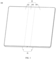
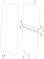
- the electronic device 100 may include a foldable apparatus 10 and a flexible display 20, and the flexible display 20 is mounted on the foldable apparatus 10.
- the flexible display 20 is configured to display an image.
- the foldable apparatus 10 may include a first housing 1, a second housing 2, and a foldable assembly 3.
- the foldable assembly 3 is connected to the first housing 1 and the second housing 2, and through movement of the foldable assembly 3, the first housing 1 and the second housing 2 are capable of being unfolded relative to each other to an unfolded state or folded relative to each other to a folded state.
- the first housing 1 and the second housing 2 may be unfolded relative to each other to the unfolded state, so that the foldable assembly 3, the foldable apparatus 10, and the electronic device 100 are all in the unfolded state.
- the flexible display 20 is unfolded along with the foldable apparatus 10.
- an included angle between the first housing 1 and the second housing 2 is 120°, 150°, 165°, 180°, or the like.
- an example in which the included angle between the first housing 1 and the second housing 2 is 180° is used for description.
- the flexible display 20 is in an unfolded state.
- the first housing 1 and the second housing 2 may be folded relative to each other to the folded state, so that the foldable assembly 3, the foldable apparatus 10, and the electronic device 100 are all in the folded state.
- the flexible display 20 is folded along with the foldable apparatus 10.
- the flexible display 20 may be located between the first housing 1 and the second housing 2.
- the flexible display 20 may be located on an inner side of the foldable apparatus 10 and wrapped by the foldable apparatus 10. It may be understood that, when the first housing 1 and the second housing 2 are in the folded state, the included angle between the first housing 1 and the second housing 2 may be approximately 0°.
- the first housing 1 and the second housing 2 may alternatively be unfolded relative to each other or folded relative to each other to an intermediate state, so that the foldable assembly 3, the foldable apparatus 10, and the electronic device 100 are all in the intermediate state.
- the intermediate state may be any state between the unfolded state and the folded state, and the flexible display 20 also changes accordingly.
- the first support surface 11 may be provided with one or more structures such as a notch, a recess, and a protrusion
- the second support surface 21 is provided with one or more structures such as a notch, a recess, and a protrusion.
- the flexible display 20 may include a first part 201, a second part 202, and a third part 203.
- the third part 203 is connected between the first part 201 and the second part 202.
- the first part 201, the third part 203, and the second part 202 are sequentially arranged.
- a part that is of the flexible display 20 and that corresponds to the first housing 1 is the first part 201, and the first part 201 may be fastened to the first housing 1.
- a part that is of the flexible display 20 and that corresponds to the second housing 2 is the second part 202, and the second part 202 may be fastened to the second housing 2.
- the plurality of components of the electronic device 100 may include but are not limited to a processor, an internal processor, an external storage interface, a universal serial bus (universal serial bus, USB) interface, a charging management module, a power management module, a battery, an antenna, a communication module, a camera module, an audio module, a speaker, a receiver, a microphone, a headset jack, a sensor module, a subscriber identity module (subscriber identity module, SIM) card interface, and one or more hard circuit boards or flexible circuit boards.
- the electronic device 100 may have more or fewer components than those described above, may combine two or more components, or may have different component configurations. A quantity, types, and locations of modules of the electronic device 100 are not limited in embodiments of this application.
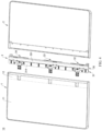
- the foldable assembly 3 includes the main shaft 31, a plurality of connection assemblies (32, 33, and 34), and a support plate 35.
- the plurality of connection assemblies (32, 33, and 34) are all connected to the main shaft 31, and the plurality of connection assemblies (32, 33, and 34) can move, to be unfolded or folded relative to the main shaft 31.
- the plurality of connection assemblies (32, 33, and 34) are further connected between the first housing 1 and the second housing 2.
- the first housing 1 may further include a third support surface 12, the third support surface 12 is located on a side that is of the first support surface 11 and that is close to the foldable assembly 3, and the third support surface 12 and the first support surface 11 may be disposed on a same plane.
- the plurality of connection assemblies (32, 33, and 34) of the foldable assembly 3 may be partially embedded into the third support surface 12.
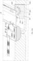
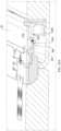
- FIG. 7 is a diagram of a partial structure of the main shaft 31 shown in FIG. 5 .
- FIG. 8A is a diagram of a cross-sectional structure of the main shaft 31 shown in FIG. 7 cut along A-A.
- FIG. 8B is a diagram of a cross-sectional structure of the main shaft 31 shown in FIG. 7 cut along B-B.
- FIG. 8C is a diagram of a cross-sectional structure of the main shaft 31 shown in FIG. 7 cut along C-C.
- FIG. 8D is a diagram of a cross-sectional structure of the main shaft 31 shown in FIG. 7 cut along D-D.
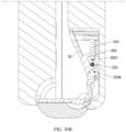
- the main inner shaft 312 includes a first arc surface 3122 and a second arc surface 3123.
- the first arc surface 3122 forms a groove wall or a part of the groove wall of the first part 3171 of the mounting groove 317, and the first arc surface 3122 is disposed facing the support surface 314 of the main shaft 31.
- the second arc surface 3123 forms a part of a groove wall of the second part 3172 of the mounting groove 317, and the second arc surface 3123 is disposed opposite to the support surface 314 of the main shaft 31.
- a central axis of the second arc surface 3123 is collinear with a central axis of the first arc surface 3122.
- the second arc surface 3123 and the first arc surface 3122 are disposed, so that the mounting groove 317 includes an equivalent arc-shaped groove, and a central axis of the arc-shaped groove is collinear with a central axis of the first arc-shaped groove 315.
- the main shaft 31 may further have a mounting space 318, and the mounting space 318 may be jointly formed by the main inner shaft 312 and the main outer shaft 311.
- the mounting space 318 is approximately located on a side that is of the mounting groove 317 and that is opposite to the support surface 314 of the main shaft 31, and the mounting space 318 is connected to the mounting groove 317.
- An opening is provided on the groove bottom of the second part 3172 of the mounting groove 317, so that the mounting space 318 is connected to the second part 3172 of the mounting groove 317.
- the first arc surface 3122 may be provided with a notch, so that an opening is provided on the groove bottom of the first part 3171 of the mounting groove 317, and the mounting space 318 is connected to the first part 3171 of the mounting groove 317.
- a length extension direction of the mounting space 318 is parallel to the extension direction of the main shaft 31.
- the main shaft 31 may be further provided with a second notch 319, the second notch 319 is located on a side that is of the main shaft 31 and that is away from the first notch 316, and the second notch 319 connects the mounting space 318 to the external space of the main shaft 31.
- the second notch 319 may be formed on the main inner shaft 312 and/or the main outer shaft 311.
- the main shaft 31 further has a positioning slot 3110, at least one positioning slot 3110 is connected to the mounting space 318, and the positioning slot 3110 is formed by jointly limiting the main inner shaft 312 and the main outer shaft 311.
- the plurality of positioning slots 3110 are spaced apart.
- the main shaft 31 may further have a second arc-shaped groove 3120, and the second arc-shaped groove 3120 may be formed by disposing the arc-shaped surface on the main inner shaft 312 opposite to the arc-shaped surface on the main outer shaft 311. Both sides of the second arc-shaped groove 3120 may extend to the support surface 314 of the main shaft 31, and some notches on the support surface 314 of the main shaft 31 are a part of the second arc-shaped groove 3120.
- the first arc-shaped groove 315 may be arranged by using the space of the main shaft 31 as much as possible. This helps improve space utilization of the main shaft 31 and reduce a thickness of the main shaft 31.
- the main inner shaft 312 is further provided with a third notch 3130, the third notch 3130 penetrates a side edge that is of the main inner shaft 312 and that is away from the first notch 316, and the third notch 3130 connects the second arc-shaped groove 3120 to the external space of the main shaft 31.
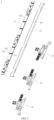
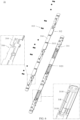
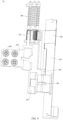
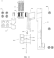
- FIG. 9 is a diagram of a structure of the bottom connection assembly 32 shown in FIG. 5 .
- FIG. 10 is a diagram of a partial exploded structure of the bottom connection assembly 32 shown in FIG. 9 .
- the bottom connection assembly 32 includes a rotation arm 321, a mounting bracket 322, a first connection arm 323, a second connection arm 324, a connection rod 325, a connection shaft 326, a synchronization assembly 327, a damping assembly 328, a first group of connectors 3291, and a second group of connectors 3292.
- the rotation arm 321 may be connected to the first housing 1 via the first group of connectors 3291, and the first group of connectors 3291 may include one or more fasteners.
- the mounting bracket 322 may be connected to the second housing 2 via the second group of connectors 3292, and the second group of connectors 3292 may include one or more fasteners.
- Both the first connection arm 323 and the second connection arm 324 are connected to the mounting bracket 322, and the connection rod 325 may be connected to the first connection arm 323 and the second connection arm 324 via the connection shaft 326.
- the synchronization assembly 327 is connected to the rotation arm 321 and the first connection arm 323, and the damping assembly 328 is also connected to the rotation arm 321 and the first connection arm 323.
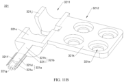
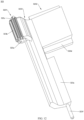
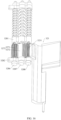
- FIG. 11A is a diagram of a structure of the rotation arm 321 shown in FIG. 10 .
- FIG. 11B is a diagram of a structure of the rotation arm 321 shown in FIG. 11A from another angle.
- the rotation arm 321 includes a first end 3211 and a second end 3212 connected to the first end 3211.
- the first end 3211 of the rotation arm 321 may be provided with a connection gear 321a, a connection rod 321b, and an arc-shaped arm 321c.
- the connection gear 321a may be an incomplete gear.
- the connection gear 321a includes a shaft part 321d and a tooth part 321e.
- the shaft part 321d of the connection gear 321a may be an incomplete shaft body, and the shaft part 321d of the connection gear 321a has a support surface 321f.
- the tooth part 321e of the connection gear 321a may be an incomplete tooth part, and the tooth part 321e of the connection gear 321a is disposed opposite to the support surface 321f of the connection gear 321a and disposed around the shaft part 321d.
- the shaft part 321d of the connection gear 321a further has a first arc-shaped surface 321g, two sides of the first arc-shaped surface 321g are connected to the support surface 321f of the connection gear 321a, and a middle part of the first arc-shaped surface 321g recesses in a direction toward the tooth part 321e of the connection gear 321a relative to the support surface 321f of the connection gear 321a.
- a central axis (not shown in the figure) of the first arc-shaped surface 321g is collinear with a central axis (not shown in the figure) of the connection gear 321a.
- connection rod 321b has a support surface 321h and a second arc-shaped surface 321i.
- the support surface 321h of the connection rod 321b and the support surface 321f of the connection gear 321a may be disposed on a same plane.
- the second arc-shaped surface 321i of the connection rod 321b is disposed opposite to the support surface 321h of the connection rod 321b, and a central axis of the second arc-shaped surface 321i is collinear with the central axis of the first arc-shaped surface 321g.
- connection rod 321b cooperates with the first arc-shaped surface 321g of the connection gear 321a, to form an equivalent arc-shaped arm.
- a central axis (not shown in the figure) of the arc-shaped arm is collinear with the central axis (not shown in the figure) of the connection gear 321a.
- End faces of two sides of the arc-shaped arm 321c may be disposed on a same plane, to form a support surface 321j of the arc-shaped arm 321c, and the support surface 321j of the arc-shaped arm 321c and the support surface 321h of the connection rod 321b may be disposed on a same plane.
- the second end 3212 of the rotation arm 321 may be approximately plate-shaped.
- the second end 3212 of the rotation arm 321 has a support surface 321k, and the support surface 321k and the support surface 321j of the arc-shaped arm 321c may be disposed on a same plane.
- the second end 3212 of the rotation arm 321 may be provided with a plurality of connection holes 321m, and the plurality of connection holes 321m may be disposed at intervals from each other.
- the plurality of connection holes 321m are configured to implement a connection relationship between the second end 3212 of the rotation arm 321 and another structure.
- the rotation arm 321 may be an integral structural member, to have high structural strength.
- the rotation arm 321 may be formed by using a computer numerical control (computer numerical control, CNC) milling process.
- CNC computer numerical control
- the rotation arm 321 may alternatively be formed by using a metal injection molding process. This is not strictly limited in embodiments of this application.
- FIG. 12 is a diagram of a structure of the first connection arm 323 shown in FIG. 10 .
- the first connection arm 323 includes a first end 3231 and a second end 3232.
- the first end 3231 of the first connection arm 323 may be provided with a rotation shaft hole 323a, and the rotation shaft hole 323a penetrates the first end 3231 of the first connection arm 323.
- the first end 3231 of the first connection arm 323 is further provided with a plurality of engagement teeth 323b and a plurality of protrusions 323c.
- the plurality of engagement teeth 323b may be located in a middle part of the first end 3231 of the first connection arm 323 and approximately located on a side that is of the first end 3231 of the first connection arm 323 and that is opposite to the second end 3232 of the first connection arm 323, and the plurality of engagement teeth 323b jointly form a teeth part, so that the first end 3231 of the first connection arm 323 forms an incomplete gear.
- the first end 3211 of the rotation arm 321 is mounted on the main shaft 31.
- the arc-shaped arm 321c at the first end 3211 of the rotation arm 321 is mounted in the first arc-shaped groove 315 of the main shaft 31
- the connection rod 321b at the first end 3211 of the rotation arm 321 is mounted on the first part 3171 of the mounting groove 317 of the main shaft 31
- the connection gear 321a at the first end 3211 of the rotation arm 321 is mounted on the second part 3172 of the mounting groove 317 of the main shaft 31.
- the second end 3212 of the rotation arm 321 is located outside the main shaft 31 through the first notch 316.
- the first housing 1 may further include a first end surface 13 close to the main shaft 31, and the second housing 2 may further include a second end surface 23 close to the main shaft 31.
- first end surface 13 faces the second end surface 23.
- the first end surface 13 is in contact with the second end surface 23.
- first housing 1 and the second housing 2 are folded relative to each other to the folded state, orientations of the first end surface 13 and the second end surface 23 are the same, and in the thickness direction of the main shaft 31, a distance between the first end surface 13 and the outer surface 3140 of the main shaft 31 is greater than a distance between the second end surface 23 and the outer surface 3140 of the main shaft 31.
- the distance between the first end surface 13 and the outer surface 3140 of the main shaft 31 is a maximum distance between a center point of the first end surface 13 and the outer surface 3140 of the main shaft 31 in the thickness direction of the main shaft 31.
- the distance may be a distance S1 between the center point of the first end surface 13 and the second area 3140b of the outer surface 3140 of the main shaft 31.
- the distance between the second end surface 23 and the outer surface 3140 of the main shaft 31 is a maximum distance between a center point of the second end surface 23 and the outer surface 3140 of the main shaft 31 in the thickness direction of the main shaft 31.
- the distance may be a distance S2 between the center point of the second end surface 23 and the second area 3140b of the outer surface 3140 of the main shaft 31.
- the first end surface 13 and the second end surface 23 may be disposed obliquely relative to the thickness direction of the main shaft 31, and when the first housing 1 and the second housing 2 are in the folded state, the first end surface 13 and the second end surface 23 may be disposed to be flush with each other, to improve appearance experience and a holding feel of the electronic device 100.
- connection rod 325 is rotatably connected to the first connection arm 323, and the other end of the connection rod 325 is rotatably connected to the second connection arm 324.
- first connection arm 323, the connection rod 325, the second connection arm 324, and the main shaft 31 may form a four-link mechanism, so that in a process in which the first housing 1 rotates relative to the second housing 2, movement actions of the first connection arm 323 and the second connection arm 324 are prevented from being stuck, to improve reliability of the mechanism.
- the synchronization assembly 327 is engaged with the first end 3211 of the rotation arm 321 and is engaged with the first end 3231 of the first connection arm 323.
- the first synchronization gear 3271 is engaged with the connection gear 321a of the rotation arm 321, to engage with the first end 3211 of the rotation arm 321.
- the second synchronization gear 3272 is engaged with the first synchronization gear 3271 and the first end 3231 of the first connection arm 323.
- a rotation action of the rotation arm 321 relative to the main shaft 31 and a rotation action of the first connection arm 323 relative to the main shaft 31 are synchronized via the synchronization assembly 327, to improve mechanism operation experience of the user.
- the first synchronization gear 3271 is located below the connection gear 321a. Because the flexible display 20 is located above the main shaft 31, in the thickness direction of the main shaft 31, the first synchronization gear 3271 is located on a side that is of the connection gear 321a and that is opposite to the flexible display 20.
- a thickness space of the main shaft 31 can be fully used through top-bottom arrangement of the connection gear 321a and the first synchronization gear 3271, and the first synchronization gear 3271 and the connection gear 321a reuse a part of a width space of the main shaft 31. This helps reduce a width size of the main shaft 31, and miniaturize the main shaft 31.
- the pitch diameter of the second synchronization gear 3272 may be different from the pitch diameter of the first synchronization gear 3271, to better adapt to a position of the first synchronization gear 3271 and a position of the first end 3231 of the first connection arm 323, and realize engaging transmission.
- the second synchronization gear 3272 is an incomplete gear, and a tooth part position and a toothless area position of the second synchronization gear 3272 may be adjusted, to reduce a movement space requirement of the second synchronization gear 3272 during movement as much as possible while ensuring that an engaging connection requirement is implemented, so as to reduce a space requirement for the main shaft 31, for example, a space requirement for the thickness direction of the main shaft 31. This facilitates thinning of the main shaft 31.
- connection gear 321a when the first housing 1 and the second housing 2 are unfolded relative to each other to the unfolded state, the tooth part 321e of the connection gear 321a faces the first synchronization gear 3271 and is located in the main shaft 31, and the support surface 321f of the connection gear 321a is flush with the support surface 314 of the main shaft 31.
- the connection gear 321a and the main shaft 31 can be jointly configured to support the flexible display 20, to improve integrity and flatness of a support environment of the flexible display 20.
- the connection gear 321a is an incomplete gear, so that a volume of the connection gear 321a is reduced when a connection relationship is met. This helps reduce the thickness of the main shaft 31 configured to mount the connection gear 321a, and facilitate thinning of the main shaft 31.
- connection gear 321a rotates relative to the main shaft 31, a part of the tooth part 321e of the connection gear 321a partially rotates out of the main shaft 31, and the support surface 321f of the connection gear 321a faces the accommodation space 30.
- the connection gear 321a may move by using a space above the main shaft 31, so that the main shaft 31 reserves only a partial space used to allow the connection gear 321a to move. This helps reduce the thickness of the main shaft 31, and miniaturize the main shaft 31.
- the rotation center 32710 of the first synchronization gear 3271 is away from the second synchronization gear 3272 relative to the rotation center 32110 of the connection gear 321a.
- positions of the rotation center 32710 of the first synchronization gear 3271 and the rotation center 32110 of the connection gear 321a are set, so that the first synchronization gear 3271 and the connection gear 321a are always in an engaged state. This avoids idle rotation, to improve mechanism reliability of the foldable apparatus 10.
- a projection of the rotation center 32710 of the first synchronization gear 3271 on the support surface 314 of the main shaft 31 is a first projection
- a projection of the rotation center 32110 of the connection gear 321a on the support surface 314 of the main shaft 31 is a second projection
- a projection of the rotation center of the second synchronization gear 3272 on the support surface 314 of the main shaft 31 is a third projection.
- a distance between the first projection and the third projection is greater than a distance between the second projection and the third projection.
- the support surface of the rotation arm 321 may be flush with the third support surface 12 of the first housing 1 and the support surface 314 of the main shaft 31, to jointly provide a flat support environment for the flexible display 20.
- the support surface of the rotation arm 321 may include the support surface 321k of the second end 3212 of the rotation arm 321, the support surface 321j of the arc-shaped arm 321c, the support surface 321h of the connection rod 321b, and the support surface 321f of the connection gear 321a.
- a partial area or an entire area of the support surface of the rotation arm 321 may alternatively be not flush with the third support surface 12 of the first housing 1 and the support surface 314 of the main shaft 31, for example, a position may be slightly lower. In this way, the flexible display 20 is not lifted, and specific structural support can be provided.
- the damping assembly 328 is connected to the synchronization assembly 327 and the first end 3231 of the first connection arm 323, and the synchronization assembly 327 is connected to the first end 3211 of the rotation arm 321.
- the second end 3212 of the rotation arm 321 is fastened to the first housing 1, and the second end 3232 of the first connection arm 323 is connected to the second housing 2 via the mounting bracket 322. Therefore, in a process in which the first housing 1 and the second housing 2 are unfolded relative to each other or folded relative to each other, the damping assembly 328 can provide damping force, so that when unfolding or folding the electronic device 100, the user can sense resistance and thrust, thereby obtaining good hand-feeling unfolding or folding experience.
- the damping assembly 328 may further make the rotation arm 321 and the first connection arm 323 to stay at some positions, so that the first housing 1 and the second housing 2 can stay at some positions, to improve use experience of the user.
- the rotation arm 321 when the rotation arm 321 meets a connection relationship with the main shaft 31, the synchronization assembly 327, and the damping assembly 328, the rotation arm 321 may not be provided with the connection rod 321b, and the arc-shaped arm 321c is directly fastened by the connection gear 321a.
- the connection gear 321a may be provided with a second arc-shaped surface 321i, the second arc-shaped surface 321i is disposed opposite to the support surface 321f of the connection gear 321a, and the second arc-shaped surface 321i may be located on a side or in a middle part of the tooth part 321e of the connection gear 321a.
- a specific structure of the rotation arm 321 is not strictly limited in embodiments of this application.
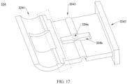
- FIG. 27 is a diagram of a structure of the support plate 35 shown in FIG. 5 from another angle.
- the support plate 35 may include a plate body 352 and a plurality of connector assemblies.
- the plurality of connector assemblies are fastened to a same side plate surface protruding from the plate body 352, and the plurality of connector assemblies are arranged in an extension direction of the plate body 352.
- a quantity of connector assemblies corresponds to the quantity of connection assemblies (32, 33, and 34) of the foldable assembly 3.
- the connector assembly may include a first rotation block 353, a second rotation block 354, and a sliding block 355.
- the first rotation block 353 includes an arc-shaped arm
- the second rotation block 354 includes an arc-shaped arm
- a center of the arc-shaped arm of the first rotation block 353 coincides with a center of the arc-shaped arm of the second rotation block 354.
- the sliding block 355 is provided with a sliding slot 3551.
- the arc-shaped arm of the first rotation block 353 is fastened to a non-support surface of the plate body 352, the non-support surface of the plate body 352 is disposed opposite to the support surface of the plate body 352, and the support surface of the plate body 352, namely, the support surface of the support plate 35, is configured to support the flexible display 20 when the first housing 1 and the second housing 2 are unfolded relative to each other to the unfolded state. Therefore, the arc-shaped arm of the first rotation block 353 is fastened to a side that is of the plate body 352 and that is opposite to the flexible display 20.
- the support plate 35 may be further provided with a plurality of compensation blocks 356, the compensation blocks 356 are protrudingly disposed on a side edge of the plate body 352, and a quantity of compensation blocks 356 corresponds to the quantity of connection assemblies (32, 33, and 34) of the foldable assembly 3.
- the plate body 352 may be provided with a plurality of avoidance notches 357, the avoidance notches 357 penetrate a thickness direction of the plate body 352, and a quantity of avoidance notches 357 corresponds to the quantity of connection assemblies (32, 33, and 34) of the foldable assembly 3.
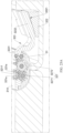
- FIG. 28 is a diagram of a structure of the foldable apparatus 10 shown in FIG. 3 from another angle.
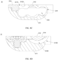
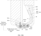
- FIG. 29A is a diagram of a cross-sectional structure of the foldable apparatus 10 shown in FIG. 28 cut along H-H.
- FIG. 29B is a diagram of a cross-sectional structure of the structure shown in FIG. 29A in another use state.
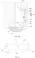
- FIG. 30A is a diagram of a cross-sectional structure of the foldable apparatus 10 shown in FIG. 28 cut along I-I.
- FIG. 30B is a diagram of a cross-sectional structure of the structure shown in FIG. 30A in another use state.
- the support plate 35 when the first housing 1 and the second housing 2 are in the unfolded state, the support plate 35 is located between the main shaft 31 and the second housing 2, and the support plate 35 shields a gap between the main shaft 31 and the second housing 2.
- the first housing 1, the main shaft 31, the support plate 35, and the second housing 2 may be configured to jointly support the flexible display 20 (referring to FIG. 3 ).
- the compensation block 356 of the support plate 35 may be at least partially located in the second notch 319 of the main shaft 31 (referring to FIG. 7 ), to increase a support area of the support plate 35.
- the second end 3242 of the second connection arm 324 may be at least partially located in the avoidance notch 357 of the support plate 35, so that the second end 3242 of the second connection arm 324 has a sufficient movable space and can compensate for the support area of the support plate 35, to increase support for the flexible display 20.
- the first rotation block 353 of the support plate 35 is mounted in the first rotation groove 3224 of the mounting bracket 322, and the support plate 35 is rotatably connected to the mounting bracket 322.
- the second rotation block 354 (referring to FIG. 27 ) of the support plate 35 may be correspondingly mounted in the second rotation groove 3225 (referring to FIG. 20 ) of the mounting bracket 322, so that a rotation connection relationship between the support plate 35 and the mounting bracket 322 is more stable and reliable.
- the sliding block 355 of the support plate 35 is at least partially located in the avoidance space 324b of the second connection arm 324, the connection shaft 326 inserted into the second connection arm 324 is inserted into the sliding slot 3551 of the sliding block 355 and can slide in the sliding slot 3551.
- the support plate 35 is slidably connected to the second connection arm 324.
- An extension direction of the sliding slot 3551 of the sliding block 355 of the support plate 35 may be a straight line shape, an arc shape, a spline curve shape, or the like. This is not strictly limited in embodiments of this application.
- the support plate 35 is rotatably connected to the mounting bracket 322 and is slidably connected to the second connection arm 324, in a process in which the first housing 1 and the second housing 2 move relative to each other, the support plate 35 moves under driving of the mounting bracket 322 and the second connection arm 324, and a movement path is accurate, to meet support requirements of the foldable apparatus 10 for the flexible display 20 in different forms.
- the first surface 322a of the mounting bracket 322 is disposed facing the support plate 35. Because the flexible display 20 is located above the support plate 35, the first surface 322a of the mounting bracket 322 is located between the flexible display 20 and the second surface 322b of the mounting bracket 322. In addition, the third surface 322c of the mounting bracket 322 is located between the main shaft 31 and the fourth surface 322d of the mounting bracket 322.
- a first included angle is formed between the first surface 322a and the support plate 35, and a distance between the support plate 35 and an end that is of the first surface 322a and that is close to the main shaft 31 is greater than a distance between the support plate 35 and an end that is of the first surface 322a and that is away from the main shaft 31. That is, an opening of the first included angle is provided toward the main shaft 31.
- the support plate 35 rotates relative to the mounting bracket 322 and approaches the first surface 322a, a second included angle is formed between the first surface 322a and the support plate 35, and the second included angle is less than the first included angle.
- the first surface 322a may be in contact with the support plate 35, to support the support plate 35.
- the arc-shaped arm of the first rotation block 353 of the support plate 35 extends from the plate body 352 in a direction away from the main shaft 31.
- a part of the arc-shaped arm of the first rotation block 353 rotates out of the first rotation groove 3224.
- a part of the arc-shaped arm of the first rotation block 353 rotates into the first rotation groove 3224.
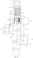
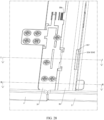
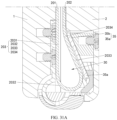
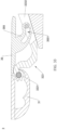
- FIG. 31A is a diagram of an internal structure of the electronic device 100 shown in FIG. 2 .
- the first part 201 of the flexible display 20 and the second part 202 of the flexible display 20 are disposed opposite to each other, and a middle part of the third part 203 of the flexible display 20 is offset toward a direction toward the second housing 2.
- the flexible display 20 deforms with the accommodation space 30, and the third part 203 of the flexible display 20 is offset toward the second housing 2.
- bending positions of the third part 203 of the flexible display 20 in this application are few. This helps reduce a risk of damaging the flexible display 20, improves reliability of the flexible display 20, and prolongs the service life of the flexible display 20.
- the support plate 35 includes a first end 35a close to the main shaft 31 and a second end 35b away from the main shaft 31.
- a distance between the first end 35a of the support plate 35 and the first housing 1 is greater than a distance between the second end 35b of the support plate 35 and the first housing 1, to form the accommodation space 30 between the support plate 35 and the first housing 1.
- the accommodation space 30 is an upper-narrow lower-wide space that is offset toward the second housing 2, and the third part 203 of the flexible display 20 is at least partially accommodated in the accommodation space 30.
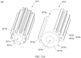
- the third part 203 of the flexible display 20 includes a first segment 2031, a second segment 2032, a third segment 2033, and a fourth segment 2034 that are sequentially connected, the first segment 2031 is connected to the first part 201 of the flexible display 20, and the fourth segment 2034 is connected to the second part 202 of the flexible display 20.
- the second segment 2032 and the fourth segment 2034 are curved segments, and the second segment 2032 and the third segment 2033 are offset in a direction toward the second housing 2. Bending positions of the flexible display 20 are located in the second segment 2032 and the fourth segment 2034.
- the middle part of the third part 203 of the flexible display 20 may be approximately located in the third segment 2033.
- the first segment 2031 and the third segment 2033 may be straight segments.
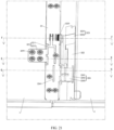
- FIG. 31B is a diagram of a structure of a fastening solution of the flexible display 20 and the foldable apparatus 10 of the electronic device 100 shown in FIG. 1 in some embodiments.
- the first segment 2031 of the third part 203 of the flexible display 20 is disposed corresponding to the third support surface 12 of the first housing 1 and the second ends 3212 of the rotation arms 321 of the plurality of connection assemblies.
- the third support surface 12 of the first housing 1 may be a plane or approximately a plane, to provide a flat support environment for the first segment 2031 of the third part 203 of the flexible display 20.
- the third segment 2033 of the third part 203 of the flexible display 20 is disposed corresponding to the support plate 35.
- the support surface 351 of the support plate 35 may be a plane or approximately a plane, to provide a flat support environment for the third segment 2033 of the third part 203 of the flexible display 20.
- the second segment 2032 of the third part 203 of the flexible display 20 is disposed close to the main shaft 31, to form one bending position of the third part 203 of the flexible display 20.
- the fourth segment 2034 of the third part 203 of the flexible display 20 is disposed corresponding to a joint between the support plate 35 and the second housing 2, to form another bending position of the third part 203 of the flexible display 20.
- the flexible display 20 when the electronic device 100 is in the folded state, the flexible display 20 forms two bending positions in the third part 203 of the flexible display 20, and the bending positions of the flexible display 20 are few. This helps improve reliability of the flexible display 20.
- the electronic device 100 may further include an adhesive layer assembly 40, and the adhesive layer assembly 40 may include a first adhesive layer to a fourth adhesive layer (401 to 404).
- the first adhesive layer 401 may be fastened to the first support surface 11 of the first housing 1, and the first adhesive layer 401 is further fastened to the first part 201 of the flexible display 20.
- the second adhesive layer 402 may be fastened to the second support surface 21 of the second housing 2, and the second adhesive layer 402 is further fastened to the second part 202 of the flexible display 20.
- the third adhesive layer 403 may be fastened to the third support surface 12 of the first housing 1, and the third adhesive layer 403 may further be fastened to the first segment 2031 of the third part 203 of the flexible display 20.
- the fourth adhesive layer 404 may be fastened to the support surface 351 of the support plate 35, and the fourth adhesive layer 404 may further be fastened to the third segment 2033 of the third part 203 of the flexible display 20.
- No adhesive layer is disposed on the support surface 314 of the main shaft 31, and the main shaft 31 is not fastened to the second segment 2032 of the third part 203 of the flexible display 20.
- No adhesive layer is disposed at the joint between the support plate 35 and the second housing 2, and the joint is not fastened to the fourth segment 2034 of the third part 203 of the flexible display 20.
- the first segment 2031 of the flexible display 20 is fastened to the first housing 1
- the second segment 2032 of the flexible display 20 is not fastened to the main shaft 31
- the third segment 2033 of the flexible display 20 is fastened to the support plate 35.
- the flexible display 20 can be bent into an expected shape in a process of switching the electronic device 100 from the unfolded state to the folded state. This reduces a risk of arching of the flexible display 20, improves reliability, and prolongs the service life of the flexible display 20.
- the adhesive layer assembly 40 may not be provided with the fourth adhesive layer 404, and the third segment 2033 of the third part 203 of the flexible display 20 and the support surface 351 of the support plate 35 may not be bonded and fastened, and can move relative to each other.
- each adhesive layer of the adhesive layer assembly 40 may be a continuous adhesive layer, or may be a disconnected adhesive layer, or may be an adhesive layer with a hollow-out area, for example, may be an entire surface-shaped/mesh-shaped adhesive layer, or includes a plurality of rubber blocks/glue spots, or includes a plurality of rubber strips, or the like. This is not strictly limited in embodiments of this application. Different adhesive layers may have same or different hardness. This is not strictly limited in embodiments of this application.
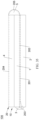
- FIG. 32 is a diagram of an exploded structure of the flexible display 20 shown in FIG. 31B .
- the flexible display 20 may include a flexible display panel 20a and a bearing plate 20b.
- the bearing plate 20b is fastened to a non-display side of the flexible display panel 20a, and a display side of the flexible display panel 20a is configured to emit light to implement display. Stiffness of the bearing plate 20b is greater than stiffness of the flexible display panel 20a.
- the bearing plate 20b is configured to provide rigid support for the flexible display panel 20a and can be bent, to improve support strength of the flexible display 20.
- the bearing plate 20b is made of a material that has specific strength, hardness, and stiffness and can be bent under external force.
- the bearing plate 20b may use a material like a stainless steel material, an aluminum alloy, a magnesium alloy, a titanium alloy, or a copper alloy.
- a material of the bearing plate 20b may alternatively be a metal matrix composite material, for example, may be a particle-reinforced aluminum-based or magnesium-based composite material like silicon carbide, aluminum oxide, boron carbide, a carbon nanotube, graphene, chromium carbide, silicon boride, titanium boride, or titanium carbide.
- the bearing plate 20b includes a first plate part 20b-1 located on the first segment 2031, a second plate part 20b-2 located on the second segment 2032, a third plate part 20b-3 located on the third segment 2033, and a fourth plate part 20b-4 located on the fourth segment 2034, and stiffness of the first plate part 20b-1 and the third plate part 20b-3 is greater than stiffness of the second plate part 20b-2 and the fourth plate part 20b-4.
- the second plate part 20b-2 and the fourth plate part 20b-4 have weak stiffness, and can be easily bent when supporting the flexible display panel 20a.
- the bearing plate 20b may further include a fifth plate part 20b-5 located on the first part 201 and a sixth plate part 20b-6 located on the second part 202.
- Strength of the fifth plate part 20b-5 and the sixth plate part 20b-6 may be the same as or similar to strength of the first plate part 20b-1.
- the bearing plate 20b may be of an integrated structure, and a plurality of plate parts of the bearing plate 20b are connected to each other and are all a part of the bearing plate 20b, so that connection between the plurality of plate parts is more secure.
- the plurality of plate parts are distinguished by using dashed lines.
- the plurality of plate parts of the bearing plate 20b may alternatively be connected and fastened to each other through welding or clamping.
- the first plate part 20b-1 and the third plate part 20b-3 may use a same or similar design, for example, may both be of a complete board structure.
- stiffness of the second plate part 20b-2 and the fourth plate part 20b-4 can be reduced by providing a through hole and a groove, reducing a thickness, splicing a soft rubber part, or the like, to achieve good bending performance and tensile performance.
- the second plate part 20b-2 may be provided with at least one groove or at least one through hole, or a thickness of the second plate part 20b-2 may be less than a thickness of the first plate part 20b-1, or the second plate part 20b-2 may use a spliced structure of a metal plate part and a soft rubber part, or the like.
- a specific material and structure of the second plate part 20b-2 are not strictly limited in this application.
- the fourth plate part 20b-4 may be provided with at least one groove or at least one through hole, or a thickness of the fourth plate part 20b-4 may be less than a thickness of the first plate part 20b-1, or the fourth plate part 20b-4 may use a spliced structure of a metal plate part and a soft rubber part, or the like.
- a specific material and structure of the fourth plate part 20b-4 are not strictly limited in this application.
- the plurality of grooves or through holes may be spaced from the top of the plate part to the bottom of the plate part.
- a shape of the groove or the through hole may be a diamond shape, a square shape, a dumbbell shape, a waist circle shape, or the like. This is not strictly limited in this application.
- FIG. 33 is a diagram of a brief structure of a partial structure of the foldable assembly 3 shown in FIG. 4 in some other embodiments.
- the support plate 35 of the foldable assembly 3 is slidably connected to the second connection arm 324 (referring to FIG. 30A ).
- the foregoing connection relationship may be replaced as follows:
- the support plate 35 of the foldable assembly 3 is slidably connected to the second end 3232 of the first connection arm 323.
- the extension direction of the sliding slot 3551 of the sliding block 355 of the support plate 35 may be a straight line shape, an arc shape, a spline curve shape, or the like.
- the first end 3231 of the first connection arm 323 is still rotatably connected to the main shaft 31.
- a partial structure of the first connection arm 323 may be adaptively adjusted with reference to the structure of the second connection arm 324 in the foregoing embodiments. Details are not described herein again.
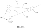
- FIG. 34A is a diagram of a moving mechanism of a partial structure of the foldable assembly 3 shown in FIG. 4 in some other embodiments.
- FIG. 34B is a diagram of a brief structure of a partial structure of the moving mechanism shown in FIG. 34A in some implementations.
- FIG. 34C is a diagram of a brief structure of a partial structure of the moving mechanism shown in FIG. 34A in some other implementations.
- the first connection arm 323 of the foldable assembly 3 is rotatably connected to the main shaft 31 and is slidably connected to the mounting bracket 322, and the second connection arm 324 is rotatably connected to the main shaft 31 and is slidably connected to the mounting bracket 322.
- the foregoing connection relationship may be replaced as follows: The first connection arm 323 of the foldable assembly 3 is rotatably connected to the main shaft 31 and is slidably connected to the mounting bracket 322, and the second connection arm 324 is rotatably connected to the main shaft 31 and is rotatably connected to the mounting bracket 322. As shown in FIG.
- the first end 3241 of the second connection arm 324 may be rotatably connected to the main shaft 31 through a virtual shaft, and the second end 3242 of the second connection arm 324 may be rotatably connected to the mounting bracket 322 through a virtual shaft.
- the first end 3241 of the second connection arm 324 may be rotatably connected to the main shaft 31 through a virtual shaft, and the second end 3242 of the second connection arm 324 may be rotatably connected to the mounting bracket 322 through a solid shaft.
- the first end 3241 of the second connection arm 324 may alternatively be rotatably connected to the main shaft 31 through a solid shaft.
- the electronic device 100 includes two housings that can be bent relative to each other.
- the electronic device 100 may alternatively be of a three-fold structure or a more than three-fold structure.
- the electronic device 100 includes three or more housings that may be bent relative to each other, and two adjacent housings are connected via the foldable assembly 3.
- a structure of the electronic device 100 may be adaptively designed with reference to descriptions of the two-fold structure in embodiments.
- FIG. 35 is a diagram of a structure of the electronic device 100 in some other embodiments according to an embodiment of this application.
- the electronic device 100 may be of a three-fold structure.
- the foldable apparatus 10 of the electronic device 100 includes the first housing 1, the foldable assembly 3, the second housing 2, a third housing 4, and a second foldable assembly 5.
- the first housing 1, the foldable assembly 3, and the second housing 2 may use the structures described in the foregoing embodiments. Details are not described herein again.
- the second foldable assembly 5 is connected to a side that is of the first housing 1 and that is away from the second housing 2, and the second foldable assembly 5 is further connected to the third housing 4.
- the first housing 1, the foldable assembly 3, the second housing 2, the third housing 4, and the second foldable assembly 5 of the electronic device 100 are sequentially connected.
- the third housing 4, the first housing 1, and the second housing 2 are folded in an S shape, and the first housing 1 is located between the third housing 4 and the second housing 2.
- the first housing 1, the second housing 2, and the third housing 4 are unfolded.
- the electronic device 100 may further include a partially unfolded state. In this case, the first housing 1 and the second housing 2 are unfolded relative to each other to the unfolded state, and the first housing 1 and the third housing 4 are folded relative to each other to the folded state.
- the first housing 1, the second housing 2, and the third housing 4 may use an equal-thickness design, or may use an unequal-thickness design.
- the thickness of the first housing 1 may be less than a thickness of a housing of the second housing 2 or the third housing 4.
- the flexible display 20 includes the first part 201, the second part 202, the third part 203, a fourth part 204, and a fifth part 205.
- the first part 201 to the third part 203 of the flexible display 20 may use the structures described in the foregoing embodiments. Details are not described herein again.
- the fourth part 204 of the flexible display 20 is connected to a side that is of the third part 203 of the flexible display 20 and that is away from the second part 202, and the fourth part 204 of the flexible display 20 is further connected to the fifth part 205 of the flexible display 20.
- the first part 201 to the fifth part 205 of the flexible display 20 are sequentially connected.
- the fourth part 204 of the flexible display 20 is disposed corresponding to the second foldable assembly 5, and the fifth part 205 of the flexible display 20 is disposed corresponding to the third housing 4.
- a part that is of the flexible display 20 and that corresponds to the third housing 4 is fastened to the third housing 4.
- a part that is of the flexible display 20 and that corresponds to the second foldable assembly 5 deforms in a process in which the first housing 1 and the third housing 4 are unfolded relative to each other or folded relative to each other.
- the electronic device 100 When the electronic device 100 is in the folded state, the first part 201 to the third part 203 of the flexible display 20 are shielded by the foldable apparatus 10, and the fourth part 204 and the fifth part 205 of the flexible display 20 are exposed, so that a display operation and/or a touch operation can be performed.
- the flexible display 20 When the electronic device 100 is in the unfolded state, the flexible display 20 is completely unfolded, so that a full-screen display and/or a touch operation can be performed.
- the electronic device 100 may further include the partially unfolded state, and a form of the flexible display 20 changes with the foldable apparatus 10.
- the flexible display 20 When the electronic device 100 is in the unfolded state, the flexible display 20 is located on a same side of the first housing 1, the second housing 2, and the third housing 4, and the first housing 1, the second housing 2, and the third housing 4 jointly support the flexible display 20.
- the electronic device 100 In the folded state, in a direction from the third housing 4 to the second housing 2, the part that is of the flexible display 20 and that corresponds to the third housing 4, the third housing 4, the first housing 1, the part that is of the flexible display 20 and that corresponds to the first housing 1, the part that is of the flexible display 20 and that corresponds to the second housing 2, and the second housing 2 are sequentially stacked.
Landscapes
- Engineering & Computer Science (AREA)
- Theoretical Computer Science (AREA)
- Computer Hardware Design (AREA)
- Physics & Mathematics (AREA)
- General Physics & Mathematics (AREA)
- Human Computer Interaction (AREA)
- General Engineering & Computer Science (AREA)
- Microelectronics & Electronic Packaging (AREA)
- Signal Processing (AREA)
- Telephone Set Structure (AREA)
- Casings For Electric Apparatus (AREA)
Applications Claiming Priority (3)
| Application Number | Priority Date | Filing Date | Title |
|---|---|---|---|
| CN202211096853 | 2022-09-06 | ||
| CN202310117311.5A CN117677094A (zh) | 2022-09-06 | 2023-01-31 | 折叠组件及电子设备 |
| PCT/CN2023/117004 WO2024051688A1 (zh) | 2022-09-06 | 2023-09-05 | 折叠组件及电子设备 |
Publications (2)
| Publication Number | Publication Date |
|---|---|
| EP4531384A1 true EP4531384A1 (de) | 2025-04-02 |
| EP4531384A4 EP4531384A4 (de) | 2025-10-15 |
Family
ID=87137810
Family Applications (1)
| Application Number | Title | Priority Date | Filing Date |
|---|---|---|---|
| EP23862382.1A Pending EP4531384A4 (de) | 2022-09-06 | 2023-09-05 | Faltanordnung und elektronische vorrichtung |
Country Status (3)
| Country | Link |
|---|---|
| EP (1) | EP4531384A4 (de) |
| CN (3) | CN117677094A (de) |
| WO (1) | WO2024051688A1 (de) |
Families Citing this family (7)
| Publication number | Priority date | Publication date | Assignee | Title |
|---|---|---|---|---|
| CN117677094A (zh) * | 2022-09-06 | 2024-03-08 | 华为技术有限公司 | 折叠组件及电子设备 |
| WO2025199796A1 (zh) * | 2024-03-27 | 2025-10-02 | 荣耀终端股份有限公司 | 转轴装置以及折叠屏设备 |
| CN120845450A (zh) * | 2024-04-26 | 2025-10-28 | 华为技术有限公司 | 转动机构和折叠电子设备 |
| CN120926177A (zh) * | 2024-05-09 | 2025-11-11 | 华为技术有限公司 | 一种转轴机构、折叠装置以及显示终端 |
| CN121408354A (zh) * | 2024-07-25 | 2026-01-27 | Oppo广东移动通信有限公司 | 折叠装置及电子设备 |
| CN120739795B (zh) * | 2024-08-23 | 2026-03-27 | 荣耀终端股份有限公司 | 转轴机构及电子设备 |
| CN121630885A (zh) * | 2024-08-31 | 2026-03-10 | 华为技术有限公司 | 折叠机构、壳体装置以及电子设备 |
Family Cites Families (9)
| Publication number | Priority date | Publication date | Assignee | Title |
|---|---|---|---|---|
| CN115665293A (zh) * | 2020-04-15 | 2023-01-31 | 华为技术有限公司 | 折叠装置及电子设备 |
| CN111614806B (zh) * | 2020-04-15 | 2021-04-09 | 华为技术有限公司 | 折叠装置及电子设备 |
| CN111885235B (zh) * | 2020-07-25 | 2022-01-11 | Oppo广东移动通信有限公司 | 可折叠壳体组件及可折叠电子设备 |
| KR102861685B1 (ko) * | 2020-10-07 | 2025-09-18 | 삼성전자주식회사 | 고정 구조를 포함하는 접이식 전자 장치 |
| CN115665290A (zh) * | 2020-10-29 | 2023-01-31 | 华为技术有限公司 | 壳体装置及电子设备 |
| CN113923279B (zh) * | 2021-01-14 | 2022-11-29 | 荣耀终端有限公司 | 折叠组件及可折叠电子设备 |
| CN113067924B (zh) * | 2021-03-19 | 2023-05-23 | 维沃移动通信有限公司 | 折叠机构、支架结构和电子设备 |
| CN115996256A (zh) * | 2021-10-19 | 2023-04-21 | 华为技术有限公司 | 电子设备、折叠组件及壳体装置 |
| CN117677094A (zh) * | 2022-09-06 | 2024-03-08 | 华为技术有限公司 | 折叠组件及电子设备 |
-
2023
- 2023-01-31 CN CN202310117311.5A patent/CN117677094A/zh active Pending
- 2023-01-31 CN CN202320224202.9U patent/CN219372800U/zh active Active
- 2023-09-05 EP EP23862382.1A patent/EP4531384A4/de active Pending
- 2023-09-05 CN CN202380058092.6A patent/CN119654856A/zh active Pending
- 2023-09-05 WO PCT/CN2023/117004 patent/WO2024051688A1/zh not_active Ceased
Also Published As
| Publication number | Publication date |
|---|---|
| WO2024051688A1 (zh) | 2024-03-14 |
| EP4531384A4 (de) | 2025-10-15 |
| CN119654856A (zh) | 2025-03-18 |
| CN117677094A (zh) | 2024-03-08 |
| CN219372800U (zh) | 2023-07-18 |
Similar Documents
| Publication | Publication Date | Title |
|---|---|---|
| EP4531384A1 (de) | Faltanordnung und elektronische vorrichtung | |
| US12277005B2 (en) | Folding apparatus and electronic device | |
| CN115665289B (zh) | 电子设备、折叠组件及壳体装置 | |
| US20230244274A1 (en) | Foldable apparatus and electronic device | |
| CN113542456B (zh) | 折叠装置及电子设备 | |
| WO2023011070A1 (zh) | 转动机构和电子设备 | |
| CN116517950A (zh) | 一种转轴机构、支撑装置和折叠屏设备 | |
| US20250048572A1 (en) | Hinge mechanism and electronic device | |
| CN219372459U (zh) | 一种折叠装置及电子设备 | |
| WO2025194982A1 (zh) | 电子设备 | |
| EP4382756A1 (de) | Faltvorrichtung und elektronische vorrichtung | |
| CN117189767A (zh) | 一种折叠装置及电子设备 | |
| EP4529146A1 (de) | Faltanordnung und elektronische vorrichtung | |
| CN117079544B (zh) | 可折叠的电子设备以及壳体装置 | |
| EP4554195A1 (de) | Faltvorrichtung und elektronische vorrichtung | |
| CN219831725U (zh) | 可折叠电子设备及折叠组件 | |
| EP4246840B1 (de) | Drehmechanismus und elektronische vorrichtung | |
| CN219268892U (zh) | 电子设备和折叠机构 | |
| CN219329106U (zh) | 可折叠电子设备 | |
| CN116055591A (zh) | 电子设备、折叠组件及壳体装置 | |
| US20250053205A1 (en) | Hinge mechanism and electronic device | |
| EP4585815A1 (de) | Faltanordnung, faltvorrichtung und elektronische vorrichtung | |
| CN117646759B (zh) | 铰链机构及电子设备 | |
| CN219755090U (zh) | 转轴机构、可折叠壳体及可折叠电子设备 | |
| CN219655079U (zh) | 一种转轴组件和可折叠电子设备 |
Legal Events
| Date | Code | Title | Description |
|---|---|---|---|
| STAA | Information on the status of an ep patent application or granted ep patent |
Free format text: STATUS: THE INTERNATIONAL PUBLICATION HAS BEEN MADE |
|
| PUAI | Public reference made under article 153(3) epc to a published international application that has entered the european phase |
Free format text: ORIGINAL CODE: 0009012 |
|
| STAA | Information on the status of an ep patent application or granted ep patent |
Free format text: STATUS: REQUEST FOR EXAMINATION WAS MADE |
|
| 17P | Request for examination filed |
Effective date: 20241224 |
|
| AK | Designated contracting states |
Kind code of ref document: A1 Designated state(s): AL AT BE BG CH CY CZ DE DK EE ES FI FR GB GR HR HU IE IS IT LI LT LU LV MC ME MK MT NL NO PL PT RO RS SE SI SK SM TR |
|
| A4 | Supplementary search report drawn up and despatched |
Effective date: 20250915 |
|
| RIC1 | Information provided on ipc code assigned before grant |
Ipc: H04M 1/02 20060101AFI20250909BHEP Ipc: G06F 1/16 20060101ALI20250909BHEP Ipc: G09F 9/30 20060101ALI20250909BHEP |
|
| DAV | Request for validation of the european patent (deleted) | ||
| DAX | Request for extension of the european patent (deleted) |