EP4530757A1 - Timepiece movement comprising an adjustment and winding mechanism comprising an internal stop for positioning a winding rod - Google Patents
Timepiece movement comprising an adjustment and winding mechanism comprising an internal stop for positioning a winding rod Download PDFInfo
- Publication number
- EP4530757A1 EP4530757A1 EP23200831.8A EP23200831A EP4530757A1 EP 4530757 A1 EP4530757 A1 EP 4530757A1 EP 23200831 A EP23200831 A EP 23200831A EP 4530757 A1 EP4530757 A1 EP 4530757A1
- Authority
- EP
- European Patent Office
- Prior art keywords
- winding
- movement
- winding stem
- adjustment
- stem
- Prior art date
- Legal status (The legal status is an assumption and is not a legal conclusion. Google has not performed a legal analysis and makes no representation as to the accuracy of the status listed.)
- Pending
Links
Images


Classifications
-
- G—PHYSICS
- G04—HOROLOGY
- G04B—MECHANICALLY-DRIVEN CLOCKS OR WATCHES; MECHANICAL PARTS OF CLOCKS OR WATCHES IN GENERAL; TIME PIECES USING THE POSITION OF THE SUN, MOON OR STARS
- G04B27/00—Mechanical devices for setting the time indicating means
- G04B27/02—Mechanical devices for setting the time indicating means by making use of the winding means
- G04B27/04—Mechanical devices for setting the time indicating means by making use of the winding means with clutch wheel
-
- G—PHYSICS
- G04—HOROLOGY
- G04B—MECHANICALLY-DRIVEN CLOCKS OR WATCHES; MECHANICAL PARTS OF CLOCKS OR WATCHES IN GENERAL; TIME PIECES USING THE POSITION OF THE SUN, MOON OR STARS
- G04B27/00—Mechanical devices for setting the time indicating means
- G04B27/02—Mechanical devices for setting the time indicating means by making use of the winding means
- G04B27/06—Mechanical devices for setting the time indicating means by making use of the winding means with rocking bar
-
- G—PHYSICS
- G04—HOROLOGY
- G04B—MECHANICALLY-DRIVEN CLOCKS OR WATCHES; MECHANICAL PARTS OF CLOCKS OR WATCHES IN GENERAL; TIME PIECES USING THE POSITION OF THE SUN, MOON OR STARS
- G04B37/00—Cases
- G04B37/06—Forming the passage for the winding stem through the case; Divided winding stems
Definitions
- the invention relates to a clockwork movement comprising a mechanism for adjusting and winding such a movement.
- the invention can be applied to a wristwatch comprising a mechanical movement.
- the invention relates to a mechanism for winding and adjusting a clockwork movement which can be positioned in different positions to perform and adjust different functions of the clockwork movement.
- the adjustment and winding of a mechanical watch is traditionally carried out by a crown that can be rotated and pulled by the user.
- This crown is generally located at the 3 o'clock position on the periphery of the watch.
- the crown is integral with a winding stem that can be moved axially, along its axis of revolution, between several axial positions corresponding to each function to be activated by the watch movement, such as manually winding the movement, setting the time, setting the date, and setting other indicators moving above or below the watch dial.
- the hand-winding position of the movement corresponds to the axial position of the winding stem furthest into the movement.
- This winding position corresponds to the neutral position of the winding stem, generally called the T1 position.
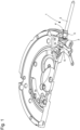
- FIG. 1 An example of the embodiment of a setting and winding mechanism 1 of a clockwork movement according to the state of the art is shown in Figure 1 , the winding stem 2 being in the winding position.
- the winding pinion 3 In this winding position, the winding pinion 3 is driven by the sliding pinion 6 which is rotationally fixed to the winding stem 2, when the latter rotates.
- the winding pinion 3 meshes with a winding crown (not shown) forming a 90° mesh.
- This 90° mesh is particularly sensitive and the slightest deviation in the positioning of the winding stem 2, and therefore in the distance between the winding pinion 3 and the winding crown, can have adverse consequences on these components, such as premature wear of the teeth.
- an external stop 4 to the winding stem 2.
- Such an external stop 4 forms a collar which comes into contact with the outside of the plate 5, at the level of a cone or support surface provided for this purpose.
- this solution involves machining a support cone on the outer transverse flank of the plate 5 to receive and house the stop 4 of the winding stem 2.
- This solution also requires checking, and correcting if necessary, the collar/cone support plane, depending on the chain of tolerances of the different parts, to ensure the correct distance of this support from the center of the watch movement, and therefore correct meshing between the winding pinion 3 and the winding crown.
- the invention aims to solve at least one of the problems cited above.
- the invention proposes a timepiece movement comprising a mechanism for adjusting and winding said timepiece movement, the adjusting and winding mechanism comprising a winding stem with an axis of revolution, having a first end cooperating with a crown and a second end opposite the crown, said winding stem being movable in rotation and in translation along the axis of revolution between a first axial position T1 of the winding stem in which a rotation of the winding stem ensures the winding of the timepiece movement, and a second axial position T2 of the winding stem in which a rotation of the winding stem ensures an adjustment of a function of the timepiece movement, characterized in that the adjusting and winding mechanism comprises a positioning stop configured to cooperate by contact with said second end of the winding stem to axially stop said winding stem in said first axial position T1.
- Such an architecture makes it possible in particular to facilitate the design and manufacture of a watch movement, by avoiding the need to create a support surface on the external transverse flank of the plate.
- the use of an internal positioning stop in the watch movement makes it easier to control its position and the chain of tolerances of the different parts.
- an architecture makes it possible to ensure optimum meshing of the different components of the adjustment and winding mechanism of the watch movement and in particular between the winding pinion of the winding stem and the winding crown.
- the positioning stop extends perpendicularly to a general plane formed by a pull jumper included in the adjustment and winding mechanism, or to a general plane formed by a bridge or by a plate included in the clockwork movement.
- the positioning stop is integral with the bridge, the plate or the pull jumper.
- the positioning stop is a pin, a peg, or a screw.
- the positioning stop is the axis around which a mobile part of the clockwork movement pivots.
- the mobile is configured to be meshed with a sliding pinion carried by the winding stem when the latter is positioned in said second axial position T2.
- the mobile is a timer return.
- the clockwork movement comprises a timer train cooperating with the timer transmission.
- the positioning stop is made of metal having a hardness equivalent to or greater than that of the winding stem.
- the positioning stop is made of steel, advantageously of a steel identical to the steel used for the winding stem. This eliminates the problems of filing generation through contact with the winding stem.
- the invention also relates to a timepiece, for example a wristwatch, comprising a timepiece movement according to the invention.
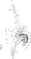
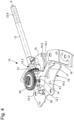
- THE figures 2 to 4 illustrate a clockwork movement 100 comprising an adjustment and winding mechanism 10 according to the invention.
- FIG. 6 represents a timepiece 200 comprising a timepiece movement 100 provided with an adjustment and winding mechanism 10 according to the invention.
- the clockwork movement 100 may be a mechanical movement, but also an electronic or electromechanical clockwork movement known from the state of the art.
- the entire adjustment and winding mechanism 10 is supported by a plate (not shown) of the clockwork movement 100 or from the plate via fixed elements or bridges fixed by ad-hoc means on the plate.
- the adjustment and winding mechanism 10 comprises a winding stem 12, with an axis of revolution X, conventionally having, at a first end, a threaded part 12.6 configured to receive a crown 50 which can be manipulated by the user outside the case 201 of the timepiece 200.
- the winding stem 12 comprises a winding pinion 13 and a sliding pinion 14, also called a sliding pinion, mounted in such a way that sliding along the X axis on a square section 12.1 of the winding stem 12, with which it is rotationally fixed thanks to its square central orifice.
- the adjustment and winding mechanism 10 comprises a pull-piece 15, pivotally mounted on the plate along a pull-piece pivot axis d15.
- the pull-piece 15 comprises a tenon 15.1 engaged and housed in an annular groove 12.2 of the winding stem 12.
- the pull-piece 15 makes it possible to transmit the axial movements of the winding stem 12, along the axis X, to the sliding pinion 14 by means of a lever 17, pivotally mounted on the plate along a lever pivot axis d17, and guided by the pivoting movements of the pull-piece 15.
- the sliding pinion 14 has a central annular groove 14.2 configured to receive and house a portion 17.1 of the rocker 17, so that the rocker 17 imposes its movements on the sliding pinion 14.
- An elastic rocker member 18 cooperates with the rocker 17 so as to exert an elastic force on the rocker 17 tending to reposition the sliding pinion 14 towards the winding pinion 13.
- the winding stem 12 is rotatable along its axis of revolution X and axially movable along this axis of revolution X, between different axial positions corresponding to different functions of the timepiece movement 100 of the timepiece 200, such as manual winding of the movement, setting the time, setting the date and/or setting other indicators moving above or below the dial of the timepiece 200.
- the adjustment and winding mechanism 10 includes a pull jumper 19 (visible in the Figure 4 ) conventionally presented in the form of a plate of general plan P1, having a fixed portion 19.2 forming a main body, configured to be secured to the plate, and a jumper spring 19.1, forming a mobile portion, cooperating with a pull pin 15.2 carried by the pull 15.
- a pull jumper 19 visible in the Figure 4
- a plate of general plan P1 having a fixed portion 19.2 forming a main body, configured to be secured to the plate, and a jumper spring 19.1, forming a mobile portion, cooperating with a pull pin 15.2 carried by the pull 15.
- the pull-out jumper 19 acts as a bridge for holding various elements of the adjustment and winding mechanism 10.
- the jumper spring 19.1 has a profile with one or more notches in which the pull pin 15.2 engages to index the pull 15 in position, and consequently the winding stem 12 in the different axial positions to define stable positions for adjusting the different functions of the watch movement 100.
- FIG. 2 particularly represents the adjustment and winding mechanism 10 in the winding position of the watch movement 100, called the first axial position T1.
- the winding stem 12 is in its most deeply recessed position in the case 201 and in the watch movement 100.
- the winding crown 20 is connected to the ratchet fixed on the barrel arbor, so that the rotation of the winding stem 12 causes the barrel spring to be wound.
- This first axial position T1 corresponds to the winding position of the watch movement 100 or the winding position of the spring.
- FIG. 3 represents the adjustment and winding mechanism 10 in a second axial position T2 which is an adjustment position of the watch movement, for example a time-setting position.
- T2 an adjustment position of the watch movement
- the user pulls axially on the crown 50 to axially move the winding stem 12 along the axis of revolution X towards the outside of the plate and the case 201 of the timepiece 200.
- the pull-out piece 15 pivots and pushes back the lever (which pivots towards the clockwork movement 100) by sliding the sliding pinion 14 along the square 12.1 of the winding stem 12.
- the sliding pinion 14 disengages from the winding pinion 13 and meshes with a return wheel (not shown) which is connected, for example, to the minute wheel and the hour gun when this second axial position T2 corresponds to a time setting position of the clockwork movement 100.
- the pull-out piece pin 15.2 is engaged in a lower notch of the jumper spring 19.1 relative to the first axial position T1.
- the number of axial adjustment or control positions of the clockwork movement 100 is not defined and may vary between one and any number achievable for a specific clockwork movement.
- the adjustment and winding mechanism 10 comprises a positioning stop 30 positioned inside the watch movement 100 in opposition to a positioning stop located on the periphery of the watch movement 100 and outside the plate.
- the positioning stop 30 is provided to prevent the winding stem 12 from moving when the latter is pushed back into the clockwork movement 100.
- the positioning stop 30 is positioned perpendicular to the axis of movement of the winding stem 12 (here the axis X), so that a second end 12.3 of the winding stem 12, opposite the crown 50 and forming the internal end of the winding stem 12, comes into contact with the positioning stop 30 when the winding stem 12 is brought into the first axial position T1.
- the positioning stop 30 is secured to the plate, a bridge or as illustrated in Figure 4 of the pull-out jumper 19 secured to the plate acting as a bridge.
- the positioning of the positioning stop 30 is easy and its relative position with respect to the center of the clockwork movement 100 is easily controllable and repeatable.
- such a positioning stop makes it possible to control the coast chain between the winding stem 12, the winding pinion 13, the positioning stop 30, the plate, the pull jumper 19 so as to guarantee optimum meshing of the winding pinion 13 with the winding crown 20 in the first axial position T1 of the winding stem 12.
- the positioning stop 30 extends perpendicularly to the general plane of the plate, a bridge or the pull-out jumper 19, so as to form a stop for the movement of the winding stem 12.
- the positioning stop 30 is for example a pin, a peg, a screw, an axis around which a mobile pivots.
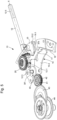
- FIG. 5 illustrates a second exemplary embodiment of an adjustment and winding mechanism according to the invention.
- This second exemplary embodiment is identical to the first exemplary embodiment described with reference to figures 2 to 4 except for the characteristics which will be specified later with reference to this Figure 5 .
- the timer return 40 of the clockwork movement 100 is positioned so that its axis around which the timer return 40 pivots constitutes the positioning stop 30' of the winding stem 12, as mentioned previously with reference to figures 2 to 4 .
- the fixed axis of the timer return 40 is advantageously used to form the positioning stop 30' and to stop the axial movement of the winding stem 12 when it returns to its first axial position T1.
- the axis of the timer return 40 is mounted securely on a bridge or the plate.
- the sliding pinion 14 meshes with the timer gear 40 which cooperates with a timer train of the clockwork movement 100.
- timer gear 40 meshes with a first intermediate gear 41 integral in rotation with a second intermediate gear 42 which meshes with a timer wheel 43.
- the timer wheel 43 is integral in rotation with a timer pinion which meshes with an hour gun 44 carrying an hour hand.
- the invention is advantageously applicable to mechanical watch movements with manual winding, but it is also applicable to electronic watches of the quartz or other type, in particular electronic watches comprising analog display members.
- the materials used for the various components are preferably metals.
- the positioning stop 30, 30' is advantageously made of steel or a metal having a hardness identical to the winding stem 12.
Landscapes
- Physics & Mathematics (AREA)
- General Physics & Mathematics (AREA)
- Electromechanical Clocks (AREA)
- Electric Clocks (AREA)
Abstract
Un aspect de l'invention concerne un mouvement d'horlogerie (100) comportant un mécanisme de réglage et de remontage (10) dudit mouvement d'horlogerie (10), le mécanisme de réglage et de remontage (10) comportant une tige de remontoir (12) d'axe de révolution (X), présentant une première extrémité (12.6) coopérant avec une couronne (50) et une deuxième extrémité (12.1) opposée à la couronne (50), ladite tige de remontoir (12) étant mobile en rotation et en translation selon l'axe de révolution (X) entre une première position axiale (T1) de la tige de remontoir (12) dans laquelle la rotation de la tige de remontoir (12) assure le remontage du mouvement d'horlogerie (100), et une deuxième position axiale (T2) de la tige de remontoir (12) dans laquelle la rotation de la tige de remontoir (12) assure un réglage d'une fonction du mouvement d'horlogerie (100), caractérisé en ce que le mécanisme de réglage et de remontage (10) comporte une butée de positionnement (30, 30') configurée pour coopérer par contact avec ladite deuxième extrémité (12.1) de la tige de remontoir (12) pour arrêter axialement ladite tige de remontoir (12) dans ladite première position axiale (T1)

Description
L'invention concerne un mouvement d'horlogerie comportant un mécanisme de réglage et de remontage d'un tel mouvement.The invention relates to a clockwork movement comprising a mechanism for adjusting and winding such a movement.
Par exemple, l'invention peut s'appliquer à une montre bracelet comportant un mouvement mécanique.For example, the invention can be applied to a wristwatch comprising a mechanical movement.
Plus particulièrement, l'invention concerne un mécanisme de remontage et de réglage d'un mouvement d'horlogerie pouvant pendre différentes positions pour réaliser et régler différentes fonctions du mouvement d'horlogerie.More particularly, the invention relates to a mechanism for winding and adjusting a clockwork movement which can be positioned in different positions to perform and adjust different functions of the clockwork movement.
Le réglage et le remontage d'une montre mécanique est effectué classiquement par une couronne qui est actionnable en rotation et en traction par l'utilisateur. Cette couronne est généralement située à la position de 3h sur le pourtour de la montre. La couronne est solidaire d'une tige de remontoir qui peut être déplacée axialement, selon son axe de révolution, entre plusieurs positions axiales correspondant à chaque fonction à actionner du mouvement d'horlogerie, telle que le remontage manuel du mouvement, la mise à l'heure, la mise à la date, et le réglage d'autres indicateurs se déplaçant au-dessus ou en dessous du cadran de la montre.The adjustment and winding of a mechanical watch is traditionally carried out by a crown that can be rotated and pulled by the user. This crown is generally located at the 3 o'clock position on the periphery of the watch. The crown is integral with a winding stem that can be moved axially, along its axis of revolution, between several axial positions corresponding to each function to be activated by the watch movement, such as manually winding the movement, setting the time, setting the date, and setting other indicators moving above or below the watch dial.
De manière classique, la position de remontage manuel du mouvement correspond à la position axiale de la tige de remontoir la plus enfoncée dans le mouvement. Cette position de remontage correspond à la position neutre de la tige de remontoir, généralement appelée position T1.Conventionally, the hand-winding position of the movement corresponds to the axial position of the winding stem furthest into the movement. This winding position corresponds to the neutral position of the winding stem, generally called the T1 position.
Un exemple de réalisation d'un mécanisme de réglage et de remontage 1 d'un mouvement d'horlogerie selon l'état de la technique est représenté à la
Dans cette position de remontage, le pignon de remontoir 3 est entrainé par le pignon coulant 6 solidaire en rotation de la tige de remontoir 2, lors d'une rotation de celle-ci. Le pignon remontoir 3 engrène avec une couronne de remontoir (non représentée) formant un engrènement à 90°. Cet engrènement à 90° est particulièrement sensible et le moindre écart de positionnement de la tige de remontoir 2, et donc de la distance entre le pignon remontoir 3 et la couronne de remontoir, peut avoir des mauvaises conséquences sur ces composants, comme par exemple une usure prématurée de la denture.In this winding position, the
Ainsi, pour s'assurer que l'on n'engrène pas sur des fonds de denture lors du remontage, il est connu d'ajouter une butée externe 4 sur la tige de remontoir 2. Une telle butée externe 4 forme une collerette qui vient en butée de contact sur l'extérieur de la platine 5, au niveau d'un cône ou surface d'appui ménagé(e) à cet effet.Thus, to ensure that one does not engage with the tooth bases during winding, it is known to add an
Toutefois, dans certaines configurations, cette solution implique d'usiner un cône d'appui sur le flanc transversal extérieur de la platine 5 pour recevoir en appui et loger la butée 4 de la tige de remontoir 2.However, in certain configurations, this solution involves machining a support cone on the outer transverse flank of the
Cette solution nécessite également de contrôler, et corriger si besoin, le plan d'appui collerette/cône, en fonction de la chaine des tolérances des différentes pièces, pour s'assurer de la bonne distance de cette appui par rapport au centre du mouvement d'horlogerie, et donc d'un engrènement correct entre le pignon remontoir 3 et la couronne de remontoir.This solution also requires checking, and correcting if necessary, the collar/cone support plane, depending on the chain of tolerances of the different parts, to ensure the correct distance of this support from the center of the watch movement, and therefore correct meshing between the winding
Enfin, cette solution engendre un contact entre la tige de remontoir 2 en acier et la platine 5 en laiton, ce qui occasionne à chaque sollicitation une dégradation de la surface de contact avec une génération de limaille.Finally, this solution creates contact between the
Par conséquent, il existe un besoin d'amélioration des mouvements d'horlogerie comportant des mécanismes de réglage et de remontage pour répondre à au moins l'une de ces problématiques.Therefore, there is a need for improvement of watch movements incorporating adjustment and winding mechanisms to address at least one of these issues.
L'invention vise à résoudre au moins un des problèmes cités précédemment.The invention aims to solve at least one of the problems cited above.
A cet effet, l'invention propose un mouvement d'horlogerie comportant un mécanisme de réglage et de remontage dudit mouvement d'horlogerie, le mécanisme de réglage et de remontage comportant une tige de remontoir d'axe de révolution, présentant une première extrémité coopérant avec une couronne et une deuxième extrémité opposée à la couronne, ladite tige de remontoir étant mobile en rotation et en translation selon l'axe de révolution entre une première position axiale T1 de la tige de remontoir dans laquelle une rotation de la tige de remontoir assure le remontage du mouvement d'horlogerie, et une deuxième position axiale T2 de la tige de remontoir dans laquelle une rotation de la tige de remontoir assure un réglage d'une fonction du mouvement d'horlogerie, caractérisé en ce que le mécanisme de réglage et de remontage comporte une butée de positionnement configurée pour coopérer par contact avec ladite deuxième extrémité de la tige de remontoir pour arrêter axialement ladite tige de remontoir dans ladite première position axiale T1.To this end, the invention proposes a timepiece movement comprising a mechanism for adjusting and winding said timepiece movement, the adjusting and winding mechanism comprising a winding stem with an axis of revolution, having a first end cooperating with a crown and a second end opposite the crown, said winding stem being movable in rotation and in translation along the axis of revolution between a first axial position T1 of the winding stem in which a rotation of the winding stem ensures the winding of the timepiece movement, and a second axial position T2 of the winding stem in which a rotation of the winding stem ensures an adjustment of a function of the timepiece movement, characterized in that the adjusting and winding mechanism comprises a positioning stop configured to cooperate by contact with said second end of the winding stem to axially stop said winding stem in said first axial position T1.
Une telle architecture permet notamment de faciliter la conception et la fabrication d'un mouvement d'horlogerie, en s'affranchissant de la réalisation d'une surface d'appui sur le flanc transversal extérieur de la platine.Such an architecture makes it possible in particular to facilitate the design and manufacture of a watch movement, by avoiding the need to create a support surface on the external transverse flank of the plate.
Selon l'invention, l'utilisation d'une butée de positionnement interne au mouvement d'horlogerie permet de contrôler plus facilement sa position et la chaine des tolérances des différentes pièces. Ainsi, une telle architecture permet de s'assurer d'un engrènement optimum des différents composants du mécanisme de réglage et de remontage du mouvement d'horlogerie et notamment entre le pignon remontoir de la tige de remontoir et la couronne de remontoir.According to the invention, the use of an internal positioning stop in the watch movement makes it easier to control its position and the chain of tolerances of the different parts. Thus, such an architecture makes it possible to ensure optimum meshing of the different components of the adjustment and winding mechanism of the watch movement and in particular between the winding pinion of the winding stem and the winding crown.
Préférentiellement, la butée de positionnement s'étend perpendiculairement par rapport à un plan général formé par un sautoir de tirette que comporte le mécanisme de réglage et de remontage, ou par rapport à un plan général formé par un pont ou par une platine que comporte le mouvement d'horlogerie.Preferably, the positioning stop extends perpendicularly to a general plane formed by a pull jumper included in the adjustment and winding mechanism, or to a general plane formed by a bridge or by a plate included in the clockwork movement.
Préférentiellement, la butée de positionnement est solidaire du pont, de la platine ou du sautoir de tirette.Preferably, the positioning stop is integral with the bridge, the plate or the pull jumper.
Préférentiellement, la butée de positionnement est une goupille, un pion, ou une vis.Preferably, the positioning stop is a pin, a peg, or a screw.
Préférentiellement, la butée de positionnement est l'axe autour duquel pivote un mobile que comporte le mouvement d'horlogerie.Preferably, the positioning stop is the axis around which a mobile part of the clockwork movement pivots.
Préférentiellement, le mobile est configuré pour être engrené avec un pignon coulant que porte la tige de remontoir lorsque celle-ci est positionnée dans ladite deuxième position axiale T2.Preferably, the mobile is configured to be meshed with a sliding pinion carried by the winding stem when the latter is positioned in said second axial position T2.
Préférentiellement, le mobile est un renvoi de minuterie.Preferably, the mobile is a timer return.
Préférentiellement, le mouvement d'horlogerie comporte un rouage de minuterie coopérant avec le renvoi de minuterie.Preferably, the clockwork movement comprises a timer train cooperating with the timer transmission.
Préférentiellement, la butée de positionnement est en métal présentant une dureté équivalente ou supérieure à la tige de remontoir. Préférentiellement, la butée de positionnement est en acier, avantageusement dans un acier identique à l'acier utilisé pour la tige de remontoir. Ainsi, on s'affranchit des problématiques de génération de limaille par contact avec la tige de remontoir.Preferably, the positioning stop is made of metal having a hardness equivalent to or greater than that of the winding stem. Preferably, the positioning stop is made of steel, advantageously of a steel identical to the steel used for the winding stem. This eliminates the problems of filing generation through contact with the winding stem.
L'invention concerne également une pièce d'horlogerie, par exemple une montre bracelet, comportant un mouvement d'horlogerie selon l'invention.The invention also relates to a timepiece, for example a wristwatch, comprising a timepiece movement according to the invention.
L'invention sera décrite ci-après de manière plus détaillée à l'aide des dessins annexés, donnés à titre d'exemples nullement limitatifs, dans lesquels :
- la
figure 1 , déjà décrite, représente en perspective un mécanisme de réglage et de remontage d'une pièce d'horlogerie selon l'état de la technique ; - la
figure 2 représente une vue en perspective en vue de dessus d'un premier exemple de réalisation d'un mécanisme de réglage et de remontage d'un mouvement d'horlogerie selon l'invention, dans une première position axiale T1 correspondant à la position de remontage du mouvement d'horlogerie ; - la
figure 3 représente une vue en perspective du premier exemple de réalisation du mécanisme de réglage et de remontage d'un mouvement d'horlogerie illustré à lafigure 2 , dans une deuxième position axiale T2 correspondant à une première position de réglage du mouvement d'horlogerie ; - la
figure 4 représente une vue en perspective en vue de dessous du premier exemple de réalisation d'un mécanisme de réglage et de remontage d'un mouvement d'horlogerie illustrée à lafigure 2 , dans la première position axiale T1 correspondant à la position de remontage du mouvement d'horlogerie ; - la
figure 5 représente une vue en perspective d'un deuxième exemple de réalisation d'un mécanisme de réglage et de remontage d'un mouvement d'horlogerie selon l'invention, dans une première position axiale T1 correspondant à la position de remontage du mouvement d'horlogerie ; - la
figure 6 représente schématiquement une pièce d'horlogerie comportant un mouvement d'horlogerie muni d'un mécanisme de réglage et de remontage selon l'invention.
- there
Figure 1 , already described, represents in perspective a mechanism for adjusting and winding a timepiece according to the state of the art; - there
Figure 2 represents a perspective view from above of a first exemplary embodiment of a mechanism for adjusting and winding a watch movement according to the invention, in a first axial position T1 corresponding to the winding position of the watch movement; - there
Figure 3 represents a perspective view of the first example of the adjustment and winding mechanism of a clockwork movement illustrated inFigure 2 , in a second axial position T2 corresponding to a first adjustment position of the clockwork movement; - there
Figure 4 represents a perspective view from below of the first example of an embodiment of a mechanism for adjusting and winding a clockwork movement illustrated inFigure 2 , in the first axial position T1 corresponding to the winding position of the clockwork movement; - there
Figure 5 represents a perspective view of a second exemplary embodiment of a mechanism for adjusting and winding a clockwork movement according to the invention, in a first axial position T1 corresponding to the winding position of the clockwork movement; - there
Figure 6 schematically represents a timepiece comprising a clock movement fitted with an adjustment and winding mechanism according to the invention.
Dans toutes les figures, les éléments communs portent les mêmes numéros de référence sauf précision contraire.In all figures, common elements bear the same reference numbers unless otherwise specified.
Les
La
Le mouvement d'horlogerie 100 peut être un mouvement mécanique, mais également un mouvement d'horlogerie électronique ou électromécanique connu de l'état de la technique.The
L'ensemble du mécanisme de réglage et de remontage 10 est supporté par une platine (non représentée) du mouvement d'horlogerie 100 ou à partir de la platine via des éléments fixes ou des ponts fixés par des moyens ad-hoc sur la platine.The entire adjustment and
Le mécanisme de réglage et de remontage 10 comporte une tige de remontoir 12, d'axe de révolution X, présentant classiquement, au niveau d'une première extrémité, une partie filetée 12.6 configurée pour recevoir une couronne 50 manipulable par l'utilisateur à l'extérieur de la boîte 201 de la pièce d'horlogerie 200.The adjustment and
La tige de remontoir 12 comporte un pignon de remontoir 13 et un pignon coulant 14, également appelé pignon baladeur, monté de manière coulissante le long de l'axe X sur une section carrée 12.1 de la tige de remontoir 12, dont il est solidaire en rotation grâce son orifice central carré.The
Le mécanisme de réglage et de remontage 10 comporte une tirette 15, montée pivotante sur la platine selon un axe de pivotement de tirette d15. La tirette 15 comporte un tenon 15.1 engagé et logé dans une rainure annulaire 12.2 de la tige de remontoir 12. La tirette 15 permet de transmettre les mouvements axiaux de la tige de remontoir 12, le long de l'axe X, au pignon baladeur 14 par l'intermédiaire d'une bascule 17, montée pivotante sur la platine selon un axe de pivotement de bascule d17, et guidée par les pivotements de la tirette 15.The adjustment and
Le pignon coulant 14 présente une gorge annulaire centrale 14.2 configurée pour recevoir et loger une portion 17.1 de la bascule 17, de sorte que la bascule 17 impose ses mouvements au pignon coulant 14.The sliding
Un organe élastique de bascule 18 coopère avec la bascule 17 de manière à exercer un effort élastique sur la bascule 17 tendant à repositionner le pignon coulant 14 vers le pignon de remontoir 13.An
Dans le mouvement d'horlogerie 100, la tige remontoir 12 est mobile en rotation selon son axe de révolution X et déplaçable axialement le long de cet axe de révolution X, entre différentes positions axiales correspondant à différentes fonctions du mouvement d'horlogerie 100 de la pièce d'horlogerie 200, telles que le remontage manuel du mouvement, la mise à l'heure, la mise à la date et/ou le réglage d'autres indicateurs se déplaçant au-dessus ou en dessous du cadran de la pièce d'horlogerie 200.In the
Le mécanisme de réglage et de remontage 10 comporte un sautoir de tirette 19 (visible à la
Le sautoir de tirette 19 fait office de pont pour le maintien de différents éléments du mécanisme de réglage et de remontage 10.The pull-
Le ressort sautoir 19.1 présente un profil présentant une ou plusieurs encoches dans lesquelles la goupille de tirette 15.2 vient s'enclencher pour indexer en position la tirette 15, et par conséquent la tige de remontoir 12 dans les différentes positions axiales pour définir des positions stables de réglage des différentes fonctions du mouvement d'horlogerie 100.The jumper spring 19.1 has a profile with one or more notches in which the pull pin 15.2 engages to index the
La
Dans cette première position axiale T1, le pignon coulant 14 engrène le pignon de remontoir 13 qui engrène une couronne de remontoir 20 avec un engrènement à 90°. Ainsi, dans cette première position axiale T1 de la tige de remontoir 12, une rotation de celle-ci engendre l'entraînement en rotation de la couronne de remontoir 20.In this first axial position T1, the sliding
De manière classique, la couronne de remontoir 20 est en lien avec le rochet fixé sur l'arbre du barillet, de sorte que la rotation de la tige de remontoir 12 occasionne l'armage du ressort de barillet. Cette première position axiale T1 correspond à la position de remontage du mouvement d'horlogerie 100 ou d'armage du ressort.Conventionally, the winding
La
En tirant la tige de remontoir 12, la tirette 15 pivote et repousse la bascule (qui pivote en direction du mouvement d'horlogerie 100) en faisant glisser le pignon coulant 14 le long du carré 12.1 de la tige de remontoir 12. Le pignon coulant 14 se désengage du pignon de remontoir 13 et engrène un renvoi (non représenté) qui est en lien, par exemple avec la roue de minuterie et le canon des heures lorsque cette deuxième position axiale T2 correspond à une position de réglage de l'heure du mouvement d'horlogerie 100. Dans cette deuxième position axiale T2, la goupille de tirette 15.2 est engagée dans un cran inférieur du ressort sautoir 19.1 par rapport à la première position axiale T1.By pulling the winding
Bien entendu, à partir de la deuxième position axiale T2, il est possible de prévoir une troisième, voire une quatrième, position axiale, correspondant à des positions de réglage d'une fonction du mouvement d'horlogerie, en tirant davantage la tige de remontoir 12 vers l'extérieur de la platine, ou de la boîte 201, pour assurer le réglage d'autres fonctions comme par exemple le réglage de date, et/ou d'une autre complication du mouvement d'horlogerie 100.Of course, from the second axial position T2, it is possible to provide a third, or even a fourth, axial position, corresponding to adjustment positions of a function of the watch movement, by pulling the winding
Le nombre de positions axiales de réglage ou de commande du mouvement d'horlogerie 100 n'est pas défini et peut varier entre une seule et tout nombre réalisable pour un mouvement d'horlogerie spécifique.The number of axial adjustment or control positions of the
En repoussant la tige de remontoir 12 en direction de la platine, les différents organes reprennent les différentes positions illustrées et décrites précédemment en référence à la
Pour assurer un bon positionnement de la tige de remontoir 12 lorsque celle-ci est repoussée dans la première position axiale T1, le mécanisme de réglage et de remontage 10 comporte une butée de positionnement 30 positionnée à intérieur du mouvement d'horlogerie 100 en opposition à une butée de positionnement située en périphérie du mouvement d'horlogerie 100 et à l'extérieur de la platine.To ensure correct positioning of the winding
La butée de positionnement 30 est ménagée pour faire obstacle au déplacement de la tige de remontoir 12 lorsque celle-ci est repoussée dans le mouvement d'horlogerie 100.The
Plus particulièrement, la butée de positionnement 30 est positionnée perpendiculairement à l'axe de déplacement de la tige de remontoir 12 (ici l'axe X), de sorte qu'une deuxième extrémité 12.3 de la tige de remontoir 12, opposée à la couronne 50 et formant l'extrémité interne de la tige de remontoir 12, vienne au contact de la butée de positionnement 30 lorsque la tige de remontoir 12 est amenée dans la première position axiale T1.More particularly, the
Ainsi, en positionnant une butée de positionnement 30 en regard de l'extrémité interne 12.3 de la tige de remontoir 12 pour que celle-ci vienne en butée de contact dans la première position axiale T1, on s'assure d'un engrènement optimum du pignon de remontoir 13 avec la couronne de remontoir 20, sans contact avec les fonds de denture, puisque la tige de remontoir 12 ne peut pas être dans une position axiale plus enfoncée. Les engrènements sont donc optimums et on minimise l'usure de l'engrènement.Thus, by positioning a
La butée de positionnement 30 est solidaire de la platine, d'un pont ou comme illustrée à la
Ainsi, une telle butée de positionnement permet de maîtriser la chaîne de côte entre la tige de remontoir 12, le pignon de remontoir 13, la butée de positionnement 30, la platine, le sautoir de tirette 19 de manière à garantir un engrènement optimum du pignon de remontoir 13 avec la couronne de remontoir 20 dans la première position axiale T1 de la tige de remontoir 12.Thus, such a positioning stop makes it possible to control the coast chain between the winding
La butée de positionnement 30 s'étend perpendiculairement par rapport au plan générale de la platine, d'un pont ou du sautoir de tirette 19, de façon à former une butée au déplacement de la tige de remontoir 12.The
La butée de positionnement 30 est par exemple une goupille, un pion, une vis, un axe autour duquel pivote un mobile.The
La
Dans ce deuxième exemple de réalisation illustré à la
Dans cette configuration, on utilise avantageusement l'axe fixe du renvoi de minuterie 40 pour former la butée de positionnement 30' et pour arrêter le déplacement axial de la tige de remontoir 12 lors de son retour dans sa première position axiale T1. Préférentiellement, l'axe du renvoi de minuterie 40 est monté solidaire sur un pont ou la platine.In this configuration, the fixed axis of the
Dans la deuxième position axiale T2 de la tige de remontoir 12, le pignon coulant 14 engrène avec le renvoi de minuterie 40 qui coopère avec un rouage de minuterie du mouvement d'horlogerie 100.In the second axial position T2 of the winding
Plus particulièrement, le renvoi de minuterie 40 engrène avec un premier renvoi intermédiaire 41 solidaire en rotation d'un deuxième renvoi intermédiaire 42 qui engrène avec une roue de minuterie 43.More particularly, the
La roue de minuterie 43 est solidaire en rotation d'un pignon de minuterie qui engrène avec un canon des heures 44 portant une aiguille des heures.The
L'invention est avantageusement applicable aux mouvements horlogers mécaniques à remontage manuel, mais elle est également applicable aux montres électroniques de type à quartz ou autre, en particulier des montres électroniques comprenant des organes d'affichage analogiques.The invention is advantageously applicable to mechanical watch movements with manual winding, but it is also applicable to electronic watches of the quartz or other type, in particular electronic watches comprising analog display members.
Les matériaux utilisés pour les différents composants sont de préférence des métaux.The materials used for the various components are preferably metals.
La butée de positionnement 30, 30' est avantageusement réalisée en acier ou dans un métal présentant une dureté identique à la tige de remontoir 12.The
Claims (10)
Priority Applications (4)
| Application Number | Priority Date | Filing Date | Title |
|---|---|---|---|
| EP23200831.8A EP4530757A1 (en) | 2023-09-29 | 2023-09-29 | Timepiece movement comprising an adjustment and winding mechanism comprising an internal stop for positioning a winding rod |
| JP2024121935A JP7755696B2 (en) | 2023-09-29 | 2024-07-29 | Clock movement with setting and winding mechanism with internal stop for positioning the winding stem |
| CN202411112451.4A CN119739020A (en) | 2023-09-29 | 2024-08-14 | Timepiece movement comprising an arrangement with an internal stop for positioning a winding stem and a winding mechanism |
| US18/811,882 US20250147467A1 (en) | 2023-09-29 | 2024-08-22 | Horological movement comprising a setting and winding mechanism with an internal stop for positioning a winding stem |
Applications Claiming Priority (1)
| Application Number | Priority Date | Filing Date | Title |
|---|---|---|---|
| EP23200831.8A EP4530757A1 (en) | 2023-09-29 | 2023-09-29 | Timepiece movement comprising an adjustment and winding mechanism comprising an internal stop for positioning a winding rod |
Publications (1)
| Publication Number | Publication Date |
|---|---|
| EP4530757A1 true EP4530757A1 (en) | 2025-04-02 |
Family
ID=88238005
Family Applications (1)
| Application Number | Title | Priority Date | Filing Date |
|---|---|---|---|
| EP23200831.8A Pending EP4530757A1 (en) | 2023-09-29 | 2023-09-29 | Timepiece movement comprising an adjustment and winding mechanism comprising an internal stop for positioning a winding rod |
Country Status (4)
| Country | Link |
|---|---|
| US (1) | US20250147467A1 (en) |
| EP (1) | EP4530757A1 (en) |
| JP (1) | JP7755696B2 (en) |
| CN (1) | CN119739020A (en) |
Citations (3)
| Publication number | Priority date | Publication date | Assignee | Title |
|---|---|---|---|---|
| CH33365A (en) * | 1905-04-04 | 1905-11-30 | D Horlogerie Berna S A Ancienn | Winding stem holder |
| JPS60113582U (en) * | 1984-01-10 | 1985-08-01 | シチズン時計株式会社 | push button structure |
| EP2469358B1 (en) * | 2010-12-21 | 2019-02-27 | Dubois & Depraz S.A. | Mechanism for transmitting axial and rotary movements between two offset shafts |
Family Cites Families (1)
| Publication number | Priority date | Publication date | Assignee | Title |
|---|---|---|---|---|
| JPS63201592A (en) * | 1987-02-17 | 1988-08-19 | Citizen Watch Co Ltd | Back structure of clock |
-
2023
- 2023-09-29 EP EP23200831.8A patent/EP4530757A1/en active Pending
-
2024
- 2024-07-29 JP JP2024121935A patent/JP7755696B2/en active Active
- 2024-08-14 CN CN202411112451.4A patent/CN119739020A/en active Pending
- 2024-08-22 US US18/811,882 patent/US20250147467A1/en active Pending
Patent Citations (3)
| Publication number | Priority date | Publication date | Assignee | Title |
|---|---|---|---|---|
| CH33365A (en) * | 1905-04-04 | 1905-11-30 | D Horlogerie Berna S A Ancienn | Winding stem holder |
| JPS60113582U (en) * | 1984-01-10 | 1985-08-01 | シチズン時計株式会社 | push button structure |
| EP2469358B1 (en) * | 2010-12-21 | 2019-02-27 | Dubois & Depraz S.A. | Mechanism for transmitting axial and rotary movements between two offset shafts |
Also Published As
| Publication number | Publication date |
|---|---|
| CN119739020A (en) | 2025-04-01 |
| US20250147467A1 (en) | 2025-05-08 |
| JP2025060407A (en) | 2025-04-10 |
| JP7755696B2 (en) | 2025-10-16 |
Similar Documents
| Publication | Publication Date | Title |
|---|---|---|
| EP3499319B1 (en) | Clutch lever and clutch device for a clockwork mechanism | |
| EP2012199B1 (en) | Timepiece fitted with a device for the control of functions and/or time indications | |
| EP3144743B1 (en) | Clock movement comprising a mechanism for correcting the date | |
| EP3278183A1 (en) | Mechanism for rewinding and/or correcting at least one clock function and device for selecting a clock function | |
| EP3492997B1 (en) | Mechanical timepiece movement comprising a chiming mechanism | |
| EP4293431A2 (en) | Display mechanism with a single dial window | |
| CH710118B1 (en) | Gear piece, time difference adjusting mechanism, watch movement, and timepiece. | |
| EP4530757A1 (en) | Timepiece movement comprising an adjustment and winding mechanism comprising an internal stop for positioning a winding rod | |
| CH721159A2 (en) | Clock movement comprising an adjustment and winding mechanism comprising an internal stop for positioning a winding stem | |
| EP3246763B1 (en) | Quick correction mechanism for clock piece | |
| EP4198639B1 (en) | Case for a timepiece comprising a correcting means | |
| EP4134757B1 (en) | Mechanism for a timepiece indicating a maximum value of a measured physical magnitude and timepiece comprising such a mechanism | |
| EP4012505B1 (en) | Timepiece device with anti-blocking mobile | |
| CH714380A2 (en) | Mechanical clockwork movement comprising a striking mechanism. | |
| EP4375763B1 (en) | Clock movement comprising a mechanism for correcting a display | |
| EP3955065B1 (en) | Tab indexing device | |
| CH717111B1 (en) | Display correction mechanism and watch movement comprising this mechanism. | |
| CH720984A1 (en) | Control mechanism for a clockwork part | |
| CH718882A2 (en) | Timepiece mechanism indicating a maximum value of a measured physical quantity and timepiece comprising such a mechanism. | |
| EP4535091A1 (en) | Clock movement provided with a device for adjusting the frequency of a mechanical resonator | |
| EP4711863A1 (en) | Device for adjusting the running of a timepiece | |
| CH682201B5 (en) | Movement automatic chronograph. | |
| EP4575662A1 (en) | Friction system for a clock movement | |
| EP0852757A1 (en) | Automatic operation correction device for a winding and hand setting device in a mechanical watch movement | |
| CH720779A1 (en) | DISPLAY DEVICE FOR CLOCK MOVEMENT |
Legal Events
| Date | Code | Title | Description |
|---|---|---|---|
| PUAI | Public reference made under article 153(3) epc to a published international application that has entered the european phase |
Free format text: ORIGINAL CODE: 0009012 |
|
| STAA | Information on the status of an ep patent application or granted ep patent |
Free format text: STATUS: THE APPLICATION HAS BEEN PUBLISHED |
|
| AK | Designated contracting states |
Kind code of ref document: A1 Designated state(s): AL AT BE BG CH CY CZ DE DK EE ES FI FR GB GR HR HU IE IS IT LI LT LU LV MC ME MK MT NL NO PL PT RO RS SE SI SK SM TR |
|
| P01 | Opt-out of the competence of the unified patent court (upc) registered |
Free format text: CASE NUMBER: APP_29127/2025 Effective date: 20250618 |
|
| STAA | Information on the status of an ep patent application or granted ep patent |
Free format text: STATUS: REQUEST FOR EXAMINATION WAS MADE |
|
| 17P | Request for examination filed |
Effective date: 20250905 |