EP4530757A1 - Uhrwerk mit einem verstell- und aufziehmechanismus mit einem internen anschlag zur positionierung eines aufzugsschafts - Google Patents
Uhrwerk mit einem verstell- und aufziehmechanismus mit einem internen anschlag zur positionierung eines aufzugsschafts Download PDFInfo
- Publication number
- EP4530757A1 EP4530757A1 EP23200831.8A EP23200831A EP4530757A1 EP 4530757 A1 EP4530757 A1 EP 4530757A1 EP 23200831 A EP23200831 A EP 23200831A EP 4530757 A1 EP4530757 A1 EP 4530757A1
- Authority
- EP
- European Patent Office
- Prior art keywords
- winding
- movement
- winding stem
- adjustment
- stem
- Prior art date
- Legal status (The legal status is an assumption and is not a legal conclusion. Google has not performed a legal analysis and makes no representation as to the accuracy of the status listed.)
- Pending
Links
Images


Classifications
-
- G—PHYSICS
- G04—HOROLOGY
- G04B—MECHANICALLY-DRIVEN CLOCKS OR WATCHES; MECHANICAL PARTS OF CLOCKS OR WATCHES IN GENERAL; TIME PIECES USING THE POSITION OF THE SUN, MOON OR STARS
- G04B27/00—Mechanical devices for setting the time indicating means
- G04B27/02—Mechanical devices for setting the time indicating means by making use of the winding means
- G04B27/04—Mechanical devices for setting the time indicating means by making use of the winding means with clutch wheel
-
- G—PHYSICS
- G04—HOROLOGY
- G04B—MECHANICALLY-DRIVEN CLOCKS OR WATCHES; MECHANICAL PARTS OF CLOCKS OR WATCHES IN GENERAL; TIME PIECES USING THE POSITION OF THE SUN, MOON OR STARS
- G04B27/00—Mechanical devices for setting the time indicating means
- G04B27/02—Mechanical devices for setting the time indicating means by making use of the winding means
- G04B27/06—Mechanical devices for setting the time indicating means by making use of the winding means with rocking bar
-
- G—PHYSICS
- G04—HOROLOGY
- G04B—MECHANICALLY-DRIVEN CLOCKS OR WATCHES; MECHANICAL PARTS OF CLOCKS OR WATCHES IN GENERAL; TIME PIECES USING THE POSITION OF THE SUN, MOON OR STARS
- G04B37/00—Cases
- G04B37/06—Forming the passage for the winding stem through the case; Divided winding stems
Definitions
- the invention relates to a clockwork movement comprising a mechanism for adjusting and winding such a movement.
- the invention can be applied to a wristwatch comprising a mechanical movement.
- the invention relates to a mechanism for winding and adjusting a clockwork movement which can be positioned in different positions to perform and adjust different functions of the clockwork movement.
- the adjustment and winding of a mechanical watch is traditionally carried out by a crown that can be rotated and pulled by the user.
- This crown is generally located at the 3 o'clock position on the periphery of the watch.
- the crown is integral with a winding stem that can be moved axially, along its axis of revolution, between several axial positions corresponding to each function to be activated by the watch movement, such as manually winding the movement, setting the time, setting the date, and setting other indicators moving above or below the watch dial.
- the hand-winding position of the movement corresponds to the axial position of the winding stem furthest into the movement.
- This winding position corresponds to the neutral position of the winding stem, generally called the T1 position.
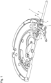
- FIG. 1 An example of the embodiment of a setting and winding mechanism 1 of a clockwork movement according to the state of the art is shown in Figure 1 , the winding stem 2 being in the winding position.
- the winding pinion 3 In this winding position, the winding pinion 3 is driven by the sliding pinion 6 which is rotationally fixed to the winding stem 2, when the latter rotates.
- the winding pinion 3 meshes with a winding crown (not shown) forming a 90° mesh.
- This 90° mesh is particularly sensitive and the slightest deviation in the positioning of the winding stem 2, and therefore in the distance between the winding pinion 3 and the winding crown, can have adverse consequences on these components, such as premature wear of the teeth.
- an external stop 4 to the winding stem 2.
- Such an external stop 4 forms a collar which comes into contact with the outside of the plate 5, at the level of a cone or support surface provided for this purpose.
- this solution involves machining a support cone on the outer transverse flank of the plate 5 to receive and house the stop 4 of the winding stem 2.
- This solution also requires checking, and correcting if necessary, the collar/cone support plane, depending on the chain of tolerances of the different parts, to ensure the correct distance of this support from the center of the watch movement, and therefore correct meshing between the winding pinion 3 and the winding crown.
- the invention aims to solve at least one of the problems cited above.
- the invention proposes a timepiece movement comprising a mechanism for adjusting and winding said timepiece movement, the adjusting and winding mechanism comprising a winding stem with an axis of revolution, having a first end cooperating with a crown and a second end opposite the crown, said winding stem being movable in rotation and in translation along the axis of revolution between a first axial position T1 of the winding stem in which a rotation of the winding stem ensures the winding of the timepiece movement, and a second axial position T2 of the winding stem in which a rotation of the winding stem ensures an adjustment of a function of the timepiece movement, characterized in that the adjusting and winding mechanism comprises a positioning stop configured to cooperate by contact with said second end of the winding stem to axially stop said winding stem in said first axial position T1.
- Such an architecture makes it possible in particular to facilitate the design and manufacture of a watch movement, by avoiding the need to create a support surface on the external transverse flank of the plate.
- the use of an internal positioning stop in the watch movement makes it easier to control its position and the chain of tolerances of the different parts.
- an architecture makes it possible to ensure optimum meshing of the different components of the adjustment and winding mechanism of the watch movement and in particular between the winding pinion of the winding stem and the winding crown.
- the positioning stop extends perpendicularly to a general plane formed by a pull jumper included in the adjustment and winding mechanism, or to a general plane formed by a bridge or by a plate included in the clockwork movement.
- the positioning stop is integral with the bridge, the plate or the pull jumper.
- the positioning stop is a pin, a peg, or a screw.
- the positioning stop is the axis around which a mobile part of the clockwork movement pivots.
- the mobile is configured to be meshed with a sliding pinion carried by the winding stem when the latter is positioned in said second axial position T2.
- the mobile is a timer return.
- the clockwork movement comprises a timer train cooperating with the timer transmission.
- the positioning stop is made of metal having a hardness equivalent to or greater than that of the winding stem.
- the positioning stop is made of steel, advantageously of a steel identical to the steel used for the winding stem. This eliminates the problems of filing generation through contact with the winding stem.
- the invention also relates to a timepiece, for example a wristwatch, comprising a timepiece movement according to the invention.
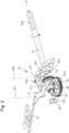
- THE figures 2 to 4 illustrate a clockwork movement 100 comprising an adjustment and winding mechanism 10 according to the invention.
- FIG. 6 represents a timepiece 200 comprising a timepiece movement 100 provided with an adjustment and winding mechanism 10 according to the invention.
- the clockwork movement 100 may be a mechanical movement, but also an electronic or electromechanical clockwork movement known from the state of the art.
- the entire adjustment and winding mechanism 10 is supported by a plate (not shown) of the clockwork movement 100 or from the plate via fixed elements or bridges fixed by ad-hoc means on the plate.
- the adjustment and winding mechanism 10 comprises a winding stem 12, with an axis of revolution X, conventionally having, at a first end, a threaded part 12.6 configured to receive a crown 50 which can be manipulated by the user outside the case 201 of the timepiece 200.
- the winding stem 12 comprises a winding pinion 13 and a sliding pinion 14, also called a sliding pinion, mounted in such a way that sliding along the X axis on a square section 12.1 of the winding stem 12, with which it is rotationally fixed thanks to its square central orifice.
- the adjustment and winding mechanism 10 comprises a pull-piece 15, pivotally mounted on the plate along a pull-piece pivot axis d15.
- the pull-piece 15 comprises a tenon 15.1 engaged and housed in an annular groove 12.2 of the winding stem 12.
- the pull-piece 15 makes it possible to transmit the axial movements of the winding stem 12, along the axis X, to the sliding pinion 14 by means of a lever 17, pivotally mounted on the plate along a lever pivot axis d17, and guided by the pivoting movements of the pull-piece 15.
- the sliding pinion 14 has a central annular groove 14.2 configured to receive and house a portion 17.1 of the rocker 17, so that the rocker 17 imposes its movements on the sliding pinion 14.
- An elastic rocker member 18 cooperates with the rocker 17 so as to exert an elastic force on the rocker 17 tending to reposition the sliding pinion 14 towards the winding pinion 13.
- the winding stem 12 is rotatable along its axis of revolution X and axially movable along this axis of revolution X, between different axial positions corresponding to different functions of the timepiece movement 100 of the timepiece 200, such as manual winding of the movement, setting the time, setting the date and/or setting other indicators moving above or below the dial of the timepiece 200.
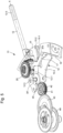
- the adjustment and winding mechanism 10 includes a pull jumper 19 (visible in the Figure 4 ) conventionally presented in the form of a plate of general plan P1, having a fixed portion 19.2 forming a main body, configured to be secured to the plate, and a jumper spring 19.1, forming a mobile portion, cooperating with a pull pin 15.2 carried by the pull 15.
- a pull jumper 19 visible in the Figure 4
- a plate of general plan P1 having a fixed portion 19.2 forming a main body, configured to be secured to the plate, and a jumper spring 19.1, forming a mobile portion, cooperating with a pull pin 15.2 carried by the pull 15.
- the pull-out jumper 19 acts as a bridge for holding various elements of the adjustment and winding mechanism 10.
- the jumper spring 19.1 has a profile with one or more notches in which the pull pin 15.2 engages to index the pull 15 in position, and consequently the winding stem 12 in the different axial positions to define stable positions for adjusting the different functions of the watch movement 100.
- FIG. 2 particularly represents the adjustment and winding mechanism 10 in the winding position of the watch movement 100, called the first axial position T1.
- the winding stem 12 is in its most deeply recessed position in the case 201 and in the watch movement 100.
- the winding crown 20 is connected to the ratchet fixed on the barrel arbor, so that the rotation of the winding stem 12 causes the barrel spring to be wound.
- This first axial position T1 corresponds to the winding position of the watch movement 100 or the winding position of the spring.
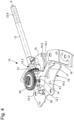
- FIG. 3 represents the adjustment and winding mechanism 10 in a second axial position T2 which is an adjustment position of the watch movement, for example a time-setting position.
- T2 an adjustment position of the watch movement
- the user pulls axially on the crown 50 to axially move the winding stem 12 along the axis of revolution X towards the outside of the plate and the case 201 of the timepiece 200.
- the pull-out piece 15 pivots and pushes back the lever (which pivots towards the clockwork movement 100) by sliding the sliding pinion 14 along the square 12.1 of the winding stem 12.
- the sliding pinion 14 disengages from the winding pinion 13 and meshes with a return wheel (not shown) which is connected, for example, to the minute wheel and the hour gun when this second axial position T2 corresponds to a time setting position of the clockwork movement 100.
- the pull-out piece pin 15.2 is engaged in a lower notch of the jumper spring 19.1 relative to the first axial position T1.
- the number of axial adjustment or control positions of the clockwork movement 100 is not defined and may vary between one and any number achievable for a specific clockwork movement.
- the adjustment and winding mechanism 10 comprises a positioning stop 30 positioned inside the watch movement 100 in opposition to a positioning stop located on the periphery of the watch movement 100 and outside the plate.
- the positioning stop 30 is provided to prevent the winding stem 12 from moving when the latter is pushed back into the clockwork movement 100.
- the positioning stop 30 is positioned perpendicular to the axis of movement of the winding stem 12 (here the axis X), so that a second end 12.3 of the winding stem 12, opposite the crown 50 and forming the internal end of the winding stem 12, comes into contact with the positioning stop 30 when the winding stem 12 is brought into the first axial position T1.
- the positioning stop 30 is secured to the plate, a bridge or as illustrated in Figure 4 of the pull-out jumper 19 secured to the plate acting as a bridge.
- the positioning of the positioning stop 30 is easy and its relative position with respect to the center of the clockwork movement 100 is easily controllable and repeatable.
- such a positioning stop makes it possible to control the coast chain between the winding stem 12, the winding pinion 13, the positioning stop 30, the plate, the pull jumper 19 so as to guarantee optimum meshing of the winding pinion 13 with the winding crown 20 in the first axial position T1 of the winding stem 12.
- the positioning stop 30 extends perpendicularly to the general plane of the plate, a bridge or the pull-out jumper 19, so as to form a stop for the movement of the winding stem 12.
- the positioning stop 30 is for example a pin, a peg, a screw, an axis around which a mobile pivots.
- FIG. 5 illustrates a second exemplary embodiment of an adjustment and winding mechanism according to the invention.
- This second exemplary embodiment is identical to the first exemplary embodiment described with reference to figures 2 to 4 except for the characteristics which will be specified later with reference to this Figure 5 .
- the timer return 40 of the clockwork movement 100 is positioned so that its axis around which the timer return 40 pivots constitutes the positioning stop 30' of the winding stem 12, as mentioned previously with reference to figures 2 to 4 .
- the fixed axis of the timer return 40 is advantageously used to form the positioning stop 30' and to stop the axial movement of the winding stem 12 when it returns to its first axial position T1.
- the axis of the timer return 40 is mounted securely on a bridge or the plate.
- the sliding pinion 14 meshes with the timer gear 40 which cooperates with a timer train of the clockwork movement 100.
- timer gear 40 meshes with a first intermediate gear 41 integral in rotation with a second intermediate gear 42 which meshes with a timer wheel 43.
- the timer wheel 43 is integral in rotation with a timer pinion which meshes with an hour gun 44 carrying an hour hand.
- the invention is advantageously applicable to mechanical watch movements with manual winding, but it is also applicable to electronic watches of the quartz or other type, in particular electronic watches comprising analog display members.
- the materials used for the various components are preferably metals.
- the positioning stop 30, 30' is advantageously made of steel or a metal having a hardness identical to the winding stem 12.
Landscapes
- Physics & Mathematics (AREA)
- General Physics & Mathematics (AREA)
- Electromechanical Clocks (AREA)
- Electric Clocks (AREA)
Priority Applications (4)
| Application Number | Priority Date | Filing Date | Title |
|---|---|---|---|
| EP23200831.8A EP4530757A1 (de) | 2023-09-29 | 2023-09-29 | Uhrwerk mit einem verstell- und aufziehmechanismus mit einem internen anschlag zur positionierung eines aufzugsschafts |
| JP2024121935A JP7755696B2 (ja) | 2023-09-29 | 2024-07-29 | 巻真を位置決めするための内部停止具を備えた設定及び巻き上げ機構を備える時計ムーブメント |
| CN202411112451.4A CN119739020A (zh) | 2023-09-29 | 2024-08-14 | 包括具有用于定位上条柄轴的内部止动件的设置和上条机构的钟表机芯 |
| US18/811,882 US20250147467A1 (en) | 2023-09-29 | 2024-08-22 | Horological movement comprising a setting and winding mechanism with an internal stop for positioning a winding stem |
Applications Claiming Priority (1)
| Application Number | Priority Date | Filing Date | Title |
|---|---|---|---|
| EP23200831.8A EP4530757A1 (de) | 2023-09-29 | 2023-09-29 | Uhrwerk mit einem verstell- und aufziehmechanismus mit einem internen anschlag zur positionierung eines aufzugsschafts |
Publications (1)
| Publication Number | Publication Date |
|---|---|
| EP4530757A1 true EP4530757A1 (de) | 2025-04-02 |
Family
ID=88238005
Family Applications (1)
| Application Number | Title | Priority Date | Filing Date |
|---|---|---|---|
| EP23200831.8A Pending EP4530757A1 (de) | 2023-09-29 | 2023-09-29 | Uhrwerk mit einem verstell- und aufziehmechanismus mit einem internen anschlag zur positionierung eines aufzugsschafts |
Country Status (4)
| Country | Link |
|---|---|
| US (1) | US20250147467A1 (de) |
| EP (1) | EP4530757A1 (de) |
| JP (1) | JP7755696B2 (de) |
| CN (1) | CN119739020A (de) |
Citations (3)
| Publication number | Priority date | Publication date | Assignee | Title |
|---|---|---|---|---|
| CH33365A (fr) * | 1905-04-04 | 1905-11-30 | D Horlogerie Berna S A Ancienn | Porte-tige de remontoir |
| JPS60113582U (ja) * | 1984-01-10 | 1985-08-01 | シチズン時計株式会社 | プツシユボタン構造 |
| EP2469358B1 (de) * | 2010-12-21 | 2019-02-27 | Dubois & Depraz S.A. | Übertragungsmechanismus von Achs- und Drehbewegungen zwischen zwei versetzt angeordneten Achsen |
Family Cites Families (1)
| Publication number | Priority date | Publication date | Assignee | Title |
|---|---|---|---|---|
| JPS63201592A (ja) * | 1987-02-17 | 1988-08-19 | Citizen Watch Co Ltd | 時計の裏回り構造 |
-
2023
- 2023-09-29 EP EP23200831.8A patent/EP4530757A1/de active Pending
-
2024
- 2024-07-29 JP JP2024121935A patent/JP7755696B2/ja active Active
- 2024-08-14 CN CN202411112451.4A patent/CN119739020A/zh active Pending
- 2024-08-22 US US18/811,882 patent/US20250147467A1/en active Pending
Patent Citations (3)
| Publication number | Priority date | Publication date | Assignee | Title |
|---|---|---|---|---|
| CH33365A (fr) * | 1905-04-04 | 1905-11-30 | D Horlogerie Berna S A Ancienn | Porte-tige de remontoir |
| JPS60113582U (ja) * | 1984-01-10 | 1985-08-01 | シチズン時計株式会社 | プツシユボタン構造 |
| EP2469358B1 (de) * | 2010-12-21 | 2019-02-27 | Dubois & Depraz S.A. | Übertragungsmechanismus von Achs- und Drehbewegungen zwischen zwei versetzt angeordneten Achsen |
Also Published As
| Publication number | Publication date |
|---|---|
| JP7755696B2 (ja) | 2025-10-16 |
| JP2025060407A (ja) | 2025-04-10 |
| CN119739020A (zh) | 2025-04-01 |
| US20250147467A1 (en) | 2025-05-08 |
Similar Documents
| Publication | Publication Date | Title |
|---|---|---|
| EP3499319B1 (de) | Kupplungswippe und kupplungsvorrichtung für uhrmechanismus | |
| EP2012199B1 (de) | Uhr, die mit einer Vorrichtung zur Steuerung von Funktionen und/oder Stundenanzeigen ausgerüstet ist | |
| EP3144743B1 (de) | Uhrwerk mit einem datumskorrektur-mechanismus | |
| EP3278183A1 (de) | Mechanismus zum rückspulen und/oder korrigieren mindestens einer taktfunktion und vorrichtung zur auswahl einer taktfunktion | |
| EP3492997B1 (de) | Mechanisches uhrwerk, das einen schlagwerkmechanismus umfasst | |
| CH710118B1 (fr) | Pièce d'engrenage, mécanisme de réglage d'une différence horaire, mouvement horloger, et pièce d'horlogerie. | |
| EP4530757A1 (de) | Uhrwerk mit einem verstell- und aufziehmechanismus mit einem internen anschlag zur positionierung eines aufzugsschafts | |
| CH721159A2 (fr) | Mouvement d'horlogerie comportant un mécanisme de réglage et de remontage comportant une butée interne de positionnement d'une tige de remontoir | |
| EP3246763B1 (de) | Schnellkorrekturmechanismus für uhr | |
| EP4198639B1 (de) | Uhrengehäuse mit einem korrekturorgan | |
| EP4134757B1 (de) | Uhrmechanismus, der einen maximalen wert einer gemessenen physikalischen grösse anzeigt, und uhr mit einem solchen mechanismus | |
| EP4012505B1 (de) | Uhrvorrichtung mit antiblockiervorrichtung | |
| CH714380A2 (fr) | Mouvement mécanique d'horlogerie comprenant un mécanisme de sonnerie. | |
| EP4375763B1 (de) | Uhrwerk, das einen mechanismus zur korrektur einer anzeige umfasst | |
| CH720984B1 (fr) | Mécanisme de commande pour pièce d'horlogerie | |
| EP3955065B1 (de) | Indexierungsvorrichtung einer zugstange | |
| CH717111B1 (fr) | Mécanisme de correction d'affichage et mouvement horloger comportant ce mécanisme. | |
| CH718882A2 (fr) | Mécanisme de pièce d'horlogerie indiquant une valeur maximale d'une grandeur physique mesurée et pièce d'horlogerie comportant un tel mécanisme. | |
| EP4535091A1 (de) | Uhrwerk, das mit einer vorrichtung zur einstellung der frequenz eines mechanischen resonators ausgestattet ist | |
| EP4711863A1 (de) | Vorrichtung zur einstellung des gangs einer uhr | |
| CH682201B5 (fr) | Mouvement de chronographe automatique à rattrapante. | |
| EP0852757A1 (de) | Ein mit einer aufzugs-und zeigereinstellungsvorrichtung vereinigter automatischer gangkorrekturmechanismus in einem mechanischen uhrwerk | |
| CH720779A1 (fr) | Dispositif d'affichage pour mouvement horloger | |
| CH715536B1 (fr) | Pièce d'horlogerie et son mécanisme sélecteur de fonction. | |
| CH701359A2 (fr) | Dispositif de correction d'une indication temporelle pour une pièce d'horlogerie. |
Legal Events
| Date | Code | Title | Description |
|---|---|---|---|
| PUAI | Public reference made under article 153(3) epc to a published international application that has entered the european phase |
Free format text: ORIGINAL CODE: 0009012 |
|
| STAA | Information on the status of an ep patent application or granted ep patent |
Free format text: STATUS: THE APPLICATION HAS BEEN PUBLISHED |
|
| AK | Designated contracting states |
Kind code of ref document: A1 Designated state(s): AL AT BE BG CH CY CZ DE DK EE ES FI FR GB GR HR HU IE IS IT LI LT LU LV MC ME MK MT NL NO PL PT RO RS SE SI SK SM TR |
|
| P01 | Opt-out of the competence of the unified patent court (upc) registered |
Free format text: CASE NUMBER: APP_29127/2025 Effective date: 20250618 |
|
| STAA | Information on the status of an ep patent application or granted ep patent |
Free format text: STATUS: REQUEST FOR EXAMINATION WAS MADE |
|
| 17P | Request for examination filed |
Effective date: 20250905 |