EP4530609A1 - Interferometrischer photonischer sensor - Google Patents
Interferometrischer photonischer sensor Download PDFInfo
- Publication number
- EP4530609A1 EP4530609A1 EP24198334.5A EP24198334A EP4530609A1 EP 4530609 A1 EP4530609 A1 EP 4530609A1 EP 24198334 A EP24198334 A EP 24198334A EP 4530609 A1 EP4530609 A1 EP 4530609A1
- Authority
- EP
- European Patent Office
- Prior art keywords
- face
- coupling device
- waveguide
- optical
- arm
- Prior art date
- Legal status (The legal status is an assumption and is not a legal conclusion. Google has not performed a legal analysis and makes no representation as to the accuracy of the status listed.)
- Granted
Links
Images



Classifications
-
- G—PHYSICS
- G02—OPTICS
- G02F—OPTICAL DEVICES OR ARRANGEMENTS FOR THE CONTROL OF LIGHT BY MODIFICATION OF THE OPTICAL PROPERTIES OF THE MEDIA OF THE ELEMENTS INVOLVED THEREIN; NON-LINEAR OPTICS; FREQUENCY-CHANGING OF LIGHT; OPTICAL LOGIC ELEMENTS; OPTICAL ANALOGUE/DIGITAL CONVERTERS
- G02F1/00—Devices or arrangements for the control of the intensity, colour, phase, polarisation or direction of light arriving from an independent light source, e.g. switching, gating or modulating; Non-linear optics
- G02F1/01—Devices or arrangements for the control of the intensity, colour, phase, polarisation or direction of light arriving from an independent light source, e.g. switching, gating or modulating; Non-linear optics for the control of the intensity, phase, polarisation or colour
- G02F1/21—Devices or arrangements for the control of the intensity, colour, phase, polarisation or direction of light arriving from an independent light source, e.g. switching, gating or modulating; Non-linear optics for the control of the intensity, phase, polarisation or colour by interference
- G02F1/225—Devices or arrangements for the control of the intensity, colour, phase, polarisation or direction of light arriving from an independent light source, e.g. switching, gating or modulating; Non-linear optics for the control of the intensity, phase, polarisation or colour by interference in an optical waveguide structure
-
- G—PHYSICS
- G01—MEASURING; TESTING
- G01N—INVESTIGATING OR ANALYSING MATERIALS BY DETERMINING THEIR CHEMICAL OR PHYSICAL PROPERTIES
- G01N21/00—Investigating or analysing materials by the use of optical means, i.e. using sub-millimetre waves, infrared, visible or ultraviolet light
- G01N21/17—Systems in which incident light is modified in accordance with the properties of the material investigated
- G01N21/41—Refractivity; Phase-affecting properties, e.g. optical path length
- G01N21/45—Refractivity; Phase-affecting properties, e.g. optical path length using interferometric methods; using Schlieren methods
-
- G—PHYSICS
- G01—MEASURING; TESTING
- G01N—INVESTIGATING OR ANALYSING MATERIALS BY DETERMINING THEIR CHEMICAL OR PHYSICAL PROPERTIES
- G01N21/00—Investigating or analysing materials by the use of optical means, i.e. using sub-millimetre waves, infrared, visible or ultraviolet light
- G01N21/75—Systems in which material is subjected to a chemical reaction, the progress or the result of the reaction being investigated
- G01N21/77—Systems in which material is subjected to a chemical reaction, the progress or the result of the reaction being investigated by observing the effect on a chemical indicator
- G01N21/7703—Systems in which material is subjected to a chemical reaction, the progress or the result of the reaction being investigated by observing the effect on a chemical indicator using reagent-clad optical fibres or optical waveguides
-
- G—PHYSICS
- G02—OPTICS
- G02F—OPTICAL DEVICES OR ARRANGEMENTS FOR THE CONTROL OF LIGHT BY MODIFICATION OF THE OPTICAL PROPERTIES OF THE MEDIA OF THE ELEMENTS INVOLVED THEREIN; NON-LINEAR OPTICS; FREQUENCY-CHANGING OF LIGHT; OPTICAL LOGIC ELEMENTS; OPTICAL ANALOGUE/DIGITAL CONVERTERS
- G02F1/00—Devices or arrangements for the control of the intensity, colour, phase, polarisation or direction of light arriving from an independent light source, e.g. switching, gating or modulating; Non-linear optics
- G02F1/01—Devices or arrangements for the control of the intensity, colour, phase, polarisation or direction of light arriving from an independent light source, e.g. switching, gating or modulating; Non-linear optics for the control of the intensity, phase, polarisation or colour
- G02F1/21—Devices or arrangements for the control of the intensity, colour, phase, polarisation or direction of light arriving from an independent light source, e.g. switching, gating or modulating; Non-linear optics for the control of the intensity, phase, polarisation or colour by interference
- G02F1/212—Mach-Zehnder type
-
- G—PHYSICS
- G02—OPTICS
- G02F—OPTICAL DEVICES OR ARRANGEMENTS FOR THE CONTROL OF LIGHT BY MODIFICATION OF THE OPTICAL PROPERTIES OF THE MEDIA OF THE ELEMENTS INVOLVED THEREIN; NON-LINEAR OPTICS; FREQUENCY-CHANGING OF LIGHT; OPTICAL LOGIC ELEMENTS; OPTICAL ANALOGUE/DIGITAL CONVERTERS
- G02F1/00—Devices or arrangements for the control of the intensity, colour, phase, polarisation or direction of light arriving from an independent light source, e.g. switching, gating or modulating; Non-linear optics
- G02F1/01—Devices or arrangements for the control of the intensity, colour, phase, polarisation or direction of light arriving from an independent light source, e.g. switching, gating or modulating; Non-linear optics for the control of the intensity, phase, polarisation or colour
- G02F1/21—Devices or arrangements for the control of the intensity, colour, phase, polarisation or direction of light arriving from an independent light source, e.g. switching, gating or modulating; Non-linear optics for the control of the intensity, phase, polarisation or colour by interference
- G02F1/215—Michelson type
-
- G—PHYSICS
- G01—MEASURING; TESTING
- G01N—INVESTIGATING OR ANALYSING MATERIALS BY DETERMINING THEIR CHEMICAL OR PHYSICAL PROPERTIES
- G01N21/00—Investigating or analysing materials by the use of optical means, i.e. using sub-millimetre waves, infrared, visible or ultraviolet light
- G01N21/17—Systems in which incident light is modified in accordance with the properties of the material investigated
- G01N21/41—Refractivity; Phase-affecting properties, e.g. optical path length
- G01N21/45—Refractivity; Phase-affecting properties, e.g. optical path length using interferometric methods; using Schlieren methods
- G01N2021/451—Refractivity; Phase-affecting properties, e.g. optical path length using interferometric methods; using Schlieren methods for determining the optical absorption
-
- G—PHYSICS
- G01—MEASURING; TESTING
- G01N—INVESTIGATING OR ANALYSING MATERIALS BY DETERMINING THEIR CHEMICAL OR PHYSICAL PROPERTIES
- G01N21/00—Investigating or analysing materials by the use of optical means, i.e. using sub-millimetre waves, infrared, visible or ultraviolet light
- G01N21/17—Systems in which incident light is modified in accordance with the properties of the material investigated
- G01N21/41—Refractivity; Phase-affecting properties, e.g. optical path length
- G01N21/45—Refractivity; Phase-affecting properties, e.g. optical path length using interferometric methods; using Schlieren methods
- G01N2021/458—Refractivity; Phase-affecting properties, e.g. optical path length using interferometric methods; using Schlieren methods using interferential sensor, e.g. sensor fibre, possibly on optical waveguide
-
- G—PHYSICS
- G01—MEASURING; TESTING
- G01N—INVESTIGATING OR ANALYSING MATERIALS BY DETERMINING THEIR CHEMICAL OR PHYSICAL PROPERTIES
- G01N21/00—Investigating or analysing materials by the use of optical means, i.e. using sub-millimetre waves, infrared, visible or ultraviolet light
- G01N21/75—Systems in which material is subjected to a chemical reaction, the progress or the result of the reaction being investigated
- G01N21/77—Systems in which material is subjected to a chemical reaction, the progress or the result of the reaction being investigated by observing the effect on a chemical indicator
- G01N2021/7756—Sensor type
- G01N2021/7763—Sample through flow
-
- G—PHYSICS
- G01—MEASURING; TESTING
- G01N—INVESTIGATING OR ANALYSING MATERIALS BY DETERMINING THEIR CHEMICAL OR PHYSICAL PROPERTIES
- G01N21/00—Investigating or analysing materials by the use of optical means, i.e. using sub-millimetre waves, infrared, visible or ultraviolet light
- G01N21/75—Systems in which material is subjected to a chemical reaction, the progress or the result of the reaction being investigated
- G01N21/77—Systems in which material is subjected to a chemical reaction, the progress or the result of the reaction being investigated by observing the effect on a chemical indicator
- G01N2021/7769—Measurement method of reaction-produced change in sensor
- G01N2021/7779—Measurement method of reaction-produced change in sensor interferometric
-
- G—PHYSICS
- G01—MEASURING; TESTING
- G01N—INVESTIGATING OR ANALYSING MATERIALS BY DETERMINING THEIR CHEMICAL OR PHYSICAL PROPERTIES
- G01N2201/00—Features of devices classified in G01N21/00
- G01N2201/06—Illumination; Optics
- G01N2201/063—Illuminating optical parts
- G01N2201/0636—Reflectors
-
- G—PHYSICS
- G02—OPTICS
- G02B—OPTICAL ELEMENTS, SYSTEMS OR APPARATUS
- G02B6/00—Light guides; Structural details of arrangements comprising light guides and other optical elements, e.g. couplings
- G02B6/10—Light guides; Structural details of arrangements comprising light guides and other optical elements, e.g. couplings of the optical waveguide type
- G02B6/12—Light guides; Structural details of arrangements comprising light guides and other optical elements, e.g. couplings of the optical waveguide type of the integrated circuit kind
- G02B2006/12133—Functions
- G02B2006/12138—Sensor
-
- G—PHYSICS
- G02—OPTICS
- G02B—OPTICAL ELEMENTS, SYSTEMS OR APPARATUS
- G02B6/00—Light guides; Structural details of arrangements comprising light guides and other optical elements, e.g. couplings
- G02B6/10—Light guides; Structural details of arrangements comprising light guides and other optical elements, e.g. couplings of the optical waveguide type
- G02B6/12—Light guides; Structural details of arrangements comprising light guides and other optical elements, e.g. couplings of the optical waveguide type of the integrated circuit kind
- G02B6/122—Basic optical elements, e.g. light-guiding paths
- G02B6/124—Geodesic lenses or integrated gratings
-
- G—PHYSICS
- G02—OPTICS
- G02B—OPTICAL ELEMENTS, SYSTEMS OR APPARATUS
- G02B6/00—Light guides; Structural details of arrangements comprising light guides and other optical elements, e.g. couplings
- G02B6/24—Coupling light guides
- G02B6/26—Optical coupling means
- G02B6/34—Optical coupling means utilising prism or grating
Definitions
- the invention lies in the field of photonic sensors, and more particularly in the field of sensors whose measurand is deduced from a measurement of variation in the optical index of an ambient medium.
- the measurand may be, for example, a concentration of target molecules in a gas or liquid (gas sensor, biosensor, etc.), or directly the optical index of a medium (refractometer).
- the invention is implemented by means of integrated photonic circuits, i.e. based on planar dielectric waveguides.
- a planar waveguide is a waveguide formed in a planar layer of an optoelectronic device.
- a planar waveguide may have a rectangular cross-section, in particular.
- L d corresponds to the distance at which the electric field intensity is divided by the constant e.
- ⁇ (750 nm -1500 nm) with SiN or Si guides in air.
- L d ⁇ 2 ⁇ 1 n eff 2 ⁇ n a 2 where n a is the optical index of the ambient medium and n eff the effective index of the guided mode.
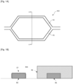
- the measuring arm B2 has an upper surface in contact with an ambient medium MA, for example a saline solution likely to contain biomolecules, while the reference arm B1 is separated from the ambient medium by a surface coating RS with a thickness much greater than L d , typically at least by a factor of 5, or even by a factor of 10.
- the upper surface of the waveguide forming the measuring arm B2 comprises a functionalization layer CF adapted to selectively fix or adsorb a target biological species (bacteria, virus, etc.) or chemical species (protein, nucleic acid, etc.). If the target biological or chemical species is present in the ambient medium, the refractive index "seen" by a light wave propagating in the measuring arm changes. This induces a phase shift relative to the light wave propagating in the reference arm, and therefore a variation in the light intensity at the output of the interferometer.
- an ambient medium MA for example a saline solution likely to contain biomolecules
- the reference arm B1 is separated from the ambient medium by
- the B1 and B2 arms of the interferometer are usually spirally wound to increase their length while maintaining the compactness of the device.
- a disadvantage of the architecture illustrated on the [ Fig. 1A] and [Fig. 1B ] is that it does not allow to differentiate a change in the refractive index of the ambient medium in volume (“bulk”) - for example caused by a change in water salinity or a change in air pressure - from an adsorption of molecules on the surface.
- the sensor signal is therefore ambiguous and tainted with error or uncertainty if the two phenomena appear simultaneously, which is often the case in practice.
- a known solution to this problem is to normalize the signal of the "interest” sensor by a so-called reference sensor, whose measuring arm is not functionalized, or is even treated to minimize adsorption (so-called “blocking” or “anti-fouling” coating, for example based on casein).
- This approach is used, for example, in the field of surface plasmon resonance sensors, see (Karlsson 1995).
- This solution requires very good chemical or biochemical recognition specificity for the sensor of interest and very good blocking for the reference sensor. In practice, it works well when the concentrations of target molecules (or those of any interferents) involved are quite low and the temporal variations of the optical index of the ambient medium (for example, when replacing a first solution to be analyzed with a rinsing buffer solution, then with a second solution to be analyzed) remain limited. When these two conditions are not met, normalization is no longer effective and a spurious signal persists.
- US 2007/0076212 discloses a device for examining atheromatous plaques by optical coherence tomography, based on a Michelson interferometer, one arm of which consists of two optical fibers intended to be introduced into a blood vessel by means of a catheter. The light emerges from the end of a first optical fiber and a mirror directs it towards the atheroma. The light backscattered by the latter is reflected by another mirror to be coupled into a second optical fiber. This sensor does not allow the measurement of a variation in the optical index of a medium.
- JP 2018066664 discloses an interferometric sensor comprising an integrated Mach-Zender interferometer, the two arms of which are formed by planar waveguides which cross a fluidic channel. This sensor is intended solely for carrying out absorption spectroscopy measurements.
- the invention aims to overcome at least in part the aforementioned drawbacks of the prior art. More particularly, it aims to provide a photonic sensor making it possible to decorrelate in a simple and effective manner the effects of changes in volume and surface refractive index.
- this aim is achieved by using an interferometer which can be described as “hybrid” because the reference arm is a waveguide, while the measuring arm has a portion propagating in free space in the ambient medium.
- An object of the invention is therefore a photonic sensor according to claim 1.
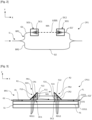
- a photonic sensor CP1 according to a first embodiment of the invention is described below with reference to the [ Fig. 2 ] - plan view - and to the [ Fig. 4], [Fig. 5 ] And [ Fig. 6 ] - sectional views of different variants.
- the photonic sensor CP1 comprises an interferometer I1 having a first arm BR1 and a second arm BR2.
- the first arm BR1 comprises a first optical waveguide G1 and a second optical waveguide G1', separated from the first optical guide G1 by a gap.
- the second arm BR2 comprises an optical waveguide G2.
- the first arm BR1 comprises at least a first coupling device DC1 between a guided propagation mode in the first optical waveguide G1 and a free propagation mode in an ambient medium MA.
- the first arm BR1 also comprises a second coupling device DC2, distinct from said first coupling device DC1, between said free propagation mode in the ambient medium MA and the guided propagation mode in the second optical waveguide G1'.
- Said first coupling device DC1 is configured to extract a light wave from the first waveguide G1' and said second coupling device DC2 to reinject it into the second waveguide G1'.
- the first BR1 arm further includes an SO1 optical system.
- the optical system SO1 is configured to direct said free propagation mode towards said second coupling device DC2.
- the first and second coupling devices DC1, DC2 and the optical system SO1 of the first arm BR1 allow a light wave passing through said first arm BR1 to carry out a part trMA of its path in said ambient medium MA, corresponding to the interval separating the first waveguide G1 from the second waveguide G1'.
- the optical waveguides G1 and/or G1' can be planar waveguides.
- the first coupling device DC1 may be a diffraction grating, in particular integrated in a planar layer CO1 comprising the first optical waveguide G1.
- the second coupling device DC2 may be a diffraction grating, in particular integrated in a planar layer CO1 comprising the second optical waveguide G1'.
- the first arm BR1 can be a measuring arm and the second arm BR2 can be a reference arm.
- the interferometer I is for example of the Mach-Zehnder type.
- a photonic sensor CP11 according to a first variant of the first embodiment is described below in relation to the [ Fig. 3 ].
- the optical waveguide G1 of the first arm BR1 of the photonic sensor CP1 is for example arranged on a substrate S1.
- the optical waveguide G1 may be located in a planar layer CO1 covering a face of the substrate S1.
- the surface of the interferometer intended to be placed in contact with the ambient medium MA may comprise at least a portion of the face FL of the planar layer CO1 opposite the face FS of the planar layer CO1 in contact with the substrate S1.
- the planar layer CO1 may comprise a stack of a first layer CO11 and a second layer CO21.
- the first layer CO11 is for example made of silicon.
- the second layer CO21 may comprise at least one dielectric material, for example silicon oxide.
- the optical waveguide G1 may be located in the second layer CO21.
- the optical system SO1 comprises a first optical reflector R1 and a second optical reflector R2.
- the first optical reflector R1 is configured to direct the light wave extracted from the first waveguide G1 by the first coupling device DC1 towards the second optical reflector R2.
- the second optical reflector R2 is configured to direct at least a portion of the light wave towards the second coupling device DC2 reinjecting it into the second waveguide G1'.
- the first optical reflector R1 comprises a prism PR1.
- the second optical reflector R2 comprises a prism PR2.
- the first optical reflector R1 comprises a first face F11, a second face F12, a third face F13.
- the second optical reflector R2 comprises a first face F21, a second face F22, a third face F23.
- the first face F11 of the first optical reflector R1 is located opposite the first coupling device DC1.
- the second face F12 of the first optical reflector R1 is inclined relative to the first face F11, in particular by an angle equal to 45° or substantially equal to 45°.
- the first face F11 of the first optical reflector R1 may be in contact with the face FL of the planar layer CO1.
- the first face F21 of the second optical reflector R2 is located opposite the second coupling device DC2.
- the second face F12 of the first optical reflector R1 is configured to reflect the light wave extracted from the first waveguide G1, in particular towards the second face F22 of the second optical reflector R2.
- the second face F22 of the second optical reflector R2 is configured to reflect the light wave, in particular towards the second coupling device DC2.
- the first face F21 of the second optical reflector R2 may be in contact with the face FL of the planar layer CO.
- the third face F13 of the first optical reflector R1 is arranged opposite the third face F23 of the second optical reflector R2.
- the first and second coupling devices DC1, DC2 may be arranged in the photonic circuit such that the third face F13 of the first optical reflector R1 is located at a distance from the third face F23 of the second optical reflector R2.
- the distance F13 - F12 is typically at least 1 mm and may reach 1 cm, or even several centimeters.
- a light wave passing through the first arm BR1 makes part of its journey in the ambient medium MA, in particular between the third face F13 of the first optical reflector R1 and the third face F23 of the second optical reflector R2.
- the third face F13 of the first optical reflector R1 may be perpendicular or substantially perpendicular (within the limits of manufacturing tolerances) to the face FL of the planar layer CO.
- the third face F23 of the second optical reflector R2 may be perpendicular or substantially perpendicular (within the limits of manufacturing tolerances) to the face FL of the planar layer CO.
- the first coupling device DC1 may comprise a diffraction grating RD11 configured to diffract the light wave propagating in the first waveguide G1 in a direction perpendicular to the free face FL of the latter.
- a grating is known in particular from (Zhang 2019).
- the second coupling device DC2 may comprise a diffraction grating RD12 configured to diffract the light wave propagating in free space in a direction perpendicular to the free face FL of the second waveguide G1' to couple it to a guided mode of the latter.
- the second face F22 of the second optical reflector R2 is inclined relative to the first face F21, in particular by an angle equal to 45° or substantially equal to 45°.
- the RD11 and RD12 diffraction gratings can be fabricated by known laser etching or direct writing techniques.
- a CP12 photonic sensor according to a second variant of the first embodiment is described below in relation to the [ Fig. 4 ]. Elements common to those of the CP11 photonic sensor are designated by the same references and are not described again below.
- the first coupling device DC1 comprises a diffraction grating RD21.
- the second coupling device DC2 comprises a diffraction grating RD22.
- the diffraction gratings RD21 and RD22 are configured to diffract the light wave propagating in the waveguide in a direction forming an angle of approximately 8° relative to the free face FL of the latter.
- the first optical reflector R1 comprises a prism PR12.
- the second optical reflector R2 comprises a prism PR22.
- the PR12 prism comprises a first face F112, a second face F122, a third face F132.
- the PR22 prism comprises a first face F212, a second face F222, a third face F232.
- the first face F112 of the prism PR12 is located opposite the first coupling device DC1.
- the second face F122 of the prism PR12 is inclined relative to the first face F112.
- the first face F212 of the prism PR22 is located opposite the second coupling device DC2.
- the second face F222 of the prism PR22 is inclined relative to the first face F212.
- the second face F122 of the prism PR12 is configured to reflect the light wave extracted from the first waveguide G1, in particular towards the second face F222 of the prism PR22.
- the second face F222 of the prism PR22 is configured to reflect the light wave, in particular towards the second coupling device DC2.
- the third face F132 of the prism PR12 is arranged opposite the third face F232 of the prism PR22.
- the reflecting faces F122 and F222 are inclined at an angle equal to 41° or substantially equal to 41° relative to the first faces F112, F212, respectively.
- a photonic sensor CP13 according to a third variant of the first embodiment is described below in relation to the [ Fig. 5 ]. Elements common to those of the CP1 photonic sensor and/or the CP2 photonic sensor are designated by the same references and are not described again below.
- the first optical reflector R1 comprises a prism PR13 having a first face F113, a second face F123, a third face F133.
- the second optical reflector R2 comprises a prism PR23 having a first face F213, a second face F223, a third face F233.
- the first face F113 of the prism PR13 is located opposite the first coupling device DC1.
- the second face F123 of the prism PR13 is inclined relative to the first face F113.
- the first face F213 of the prism PR13 is located opposite the second coupling device DC2.
- the second face F223 of the prism PR23 is inclined relative to the first face F213.
- the inclination of the faces F123 and F223 is chosen according to the diffraction angles of the diffraction gratings so that the light wave reflected on the second face F123 of the prism PR13 propagates in a parallel or substantially parallel manner to the plane (X, Y).
- the second face F123 of the prism PR13 is configured to reflect the light wave extracted from the first waveguide G1, in particular towards the second face F223 of the lens L2.
- the second face F223 of the prism PR23 is configured to reflect the light wave, in particular towards the second coupling device DC2.
- the third face F133 of the prism PR13 1 is arranged opposite the third face F233 of the prism PR23.
- the third face F133 of the prism PR13 is convex, so as to form a converging lens L1 adapted to collimate the light beam coming from the coupling device DC1 and reflected by the second face F123.
- the third face F233 of the prism PR23 is convex, so as to form a converging lens L2.
- the lens L2 is intended to focus the light wave towards the second coupling device DC2.
- a CP14 photonic sensor according to a fourth variant of the first embodiment is described below in relation to the [ Fig. 6 ]. Elements common to those of the photonic sensor CP1 and/or the photonic sensor CP2 and/or the photonic sensor CP3 are designated by the same references and are not described again below.
- the first optical reflector R1 comprises a PR14 prism.
- the second optical reflector R2 comprises a PR24 prism.
- the PR14 prism comprises a first face F114, a second face F124, a third face F134.
- the PR24 prism comprises a first face F214, a second face F224, a third face F234.
- the first face F114 of the prism PR14 is located opposite the first coupling device DC1.
- the second face F124 of the prism PR14 is inclined relative to the first face F114.
- the first face F214 of the prism PR24 is located opposite the second coupling device DC2.
- the second face F224 of the prism PR24 is inclined relative to the first face F214.
- the second face F124 of the prism PR14 is configured to reflect the light wave extracted from the first waveguide G1, in particular towards the second face F224 of the prism PR24.
- the second face F224 of the prism PR24 is configured to reflect the light wave, in particular towards the second coupling device DC2.
- the third face F134 of the prism PR14 is arranged opposite the third face F234 of the prism PR24.
- the second face F124 of the prism PR14 can be concave, on the side oriented towards the first coupling device DC1, in particular to focus or collimate the light wave by reflecting it.
- the second face F224 of the prism PR24 can be concave, on the side facing the second coupling device DC2, in particular to collimate the light wave by reflecting it.
- the inclination of the faces F124 and F224 is chosen according to the diffraction angles of the diffraction gratings so that the light wave reflected on the second face F123 of the reflector R1 propagates in a manner parallel or substantially parallel to the plane (X, Y).
- the third variant of the first embodiment can be combined with the first, second or fourth variant of the first embodiment.
- the light wave extracted from the first waveguide G1 can be reflected on the second face F12, F122, F123, F124 of the first optical reflector R1 by total internal reflection.
- the light wave can then also be reflected on the second face F22, F222, F223, F224 of the second optical reflector R2 by total internal reflection.
- the second face F12, F122, F123, F124 of the first optical reflector R1 may be covered with a reflective layer or a reflective coating or a reflective thin film CR1, on the side of the second face F12, F122, F123, F124 facing the first coupling device DC1.
- the reflective layer CR1 may comprise at least one metallic material, for example gold.
- the second face F22, F222, F223, F224 of the second optical reflector R2 may be covered with a reflective layer or a reflective coating or a reflective thin film CR2, on the side of the second face F22, F222, F223, F224 facing the second coupling device DC2.
- the reflective layer CR2 may comprise at least one metallic material, for example gold.
- the first optical reflector R1 and the second optical reflector R2 can be manufactured by three-dimensional printing, also called 3D printing, in particular exploiting two-photon polymerization as described by (Dietrich 2018) or direct laser writing as described by (Malinauskas 2012).
- a photonic sensor C2 according to a second embodiment of the invention is described below with reference to the [ Fig. 7 ].
- This second embodiment differs from the first embodiment essentially by the structure of the optical system allowing the free propagation of the light wave in the ambient environment.
- the photonic sensor C2 comprises an interferometer I2, for example of the Mach-Zehnder type, having a first arm BR12 and a second arm.
- the first arm BR12 comprises an optical waveguide G12.
- the first arm BR12 comprises a first coupling device DC12 between a guided propagation mode in the waveguide and a free propagation mode in an ambient medium MA.
- the first arm BR12 comprises a second coupling device DC22 between said free propagation mode in the ambient medium and a guided propagation mode in the waveguide G12.
- the second coupling device DC22 is in particular distinct from said first coupling device DC12.
- the first and second coupling devices DC12, DC22 may be diffraction gratings.
- the first arm BR12 comprises an optical system SO2 configured to direct said free propagation mode towards said second coupling device DC2.
- the first BR12 arm can be a measuring arm and the second arm can be a reference arm.
- the second arm may have a surface that can be brought into contact with an ambient medium MA and having a functionalization layer allowing the specific fixation of chemical or biological species.
- the G12 optical waveguide can be a planar waveguide.
- the first coupling device DC12 is in particular configured to extract a light wave from the waveguide G12.
- the second coupling device DC22 is in particular configured to reinject the light wave into the waveguide G12.
- the optical system SO2 of the first arm BR12 comprises a first optical reflector R12 and a second optical reflector R22.
- the G12 optical waveguide is for example arranged on an S12 substrate.
- the optical waveguide G12 may be located in a planar layer CO2 covering a face of the substrate S12.
- the surface of the interferometer I intended to be placed in contact with an ambient medium MA may comprise at least a portion of the face FL2 of the planar layer CO2 opposite the face FS2 of the planar layer CO in contact with the substrate S12.
- the planar CO2 layer may comprise a stack of a first CO12 layer and a second CO22 layer.
- the first CO12 layer is for example made of silicon.
- the second CO22 layer may comprise at least one dielectric material, for example silicon oxide.
- the optical waveguide G12 may be located in the second CO22 layer.
- the first optical reflector R12 is configured to direct the light wave extracted from the optical waveguide G12 by the first coupling device DC12 towards the second optical reflector R22, which is itself configured to direct said light wave towards the second coupling device DC22 reinjecting it into the waveguide G12.
- the first optical reflector R12 comprises an inclined face FI1.
- the second optical reflector R22 comprises an inclined face FI2.
- the inclined face FI1 of the first optical reflector R12 is configured to reflect the light wave extracted from the waveguide G12, in particular towards the inclined face FI2 of the second optical reflector R22.
- the inclined face FI2 of the second optical reflector R22 is configured to reflect the light wave, in particular towards the second coupling device DC22.
- the inclined face FI1 and the inclined face FI2 of the first and second optical reflectors R12, R22, respectively, are in particular formed from first and second side walls PL1, PL2 of a trench T obtained by anisotropic wet etching of a monocrystalline substrate or a monocrystalline layer S2, for example made of silicon.
- the inclined face FI1 of the first optical reflector R12 may be inclined relative to the face FL2 of the planar layer CO2, in particular by an angle equal to 54.7° or substantially equal to 54.7°, which corresponds to the orientation of a crystalline plane ⁇ 1 1 1 ⁇ of a silicon substrate.
- the first and second optical reflectors R12, R22 form or delimit, with the waveguide G12, a fluid conduit CF for said ambient medium MA.
- a light wave OL passing through said first arm BR12 carries out part of its path in said ambient medium MA, inside the fluid conduit CF.
- the CF fluid conduit is, for example, a micro-fluid conduit.
- a micro-conduit is understood to mean a conduit with millimeter or sub-millimeter dimensions.
- the inclined face FI1 of the first optical reflector R12 and the inclined face FI2 of the second optical reflector R22 may be covered with a reflective layer or a reflective coating or a reflective thin film, on the side facing the first coupling device DC12 and on the side facing the second coupling device DC12. DC12 coupling, respectively.
- the reflective layer may comprise at least one metallic material, for example gold.
- the reflective layer may be of the Bragg mirror type, formed in particular by a plurality of flat silicon oxide (SiO2) surfaces and by a plurality of flat silicon nitride (SiN) surfaces.
- the T trench can be made by wet etching.
- an SU surface extending along a ⁇ 100 ⁇ or ⁇ 010 ⁇ or ⁇ 001 ⁇ crystal plane of a monocrystalline silicon substrate is covered with an HM mask. Chemical etching is then carried out through an opening in the mask.
- the trench T comprises a first sidewall PL1 and a second sidewall PL2.
- the anisotropic wet etching can be carried out so that the first and second sidewalls PL1, PL2 extend along a ⁇ 111 ⁇ crystal plane.
- the trench T may further comprise a bottom F which may further delimit the fluid conduit CF after assembly of at least a portion of the monocrystalline layer or of the monocrystalline substrate S2 on the layer CO2.
- the fluid conduit CF may have a trapezoidal section in a plane (X, Z).
- the bottom F may be covered with a reflective layer or a reflective coating or a reflective thin film, in particular the same layer as that covering the first and second inclined faces FI1, FI2.
- An advantage of a C2 photonic sensor of the type described in connection with the [ Fig. 7 ] is related to the fact that it is quick to manufacture and has a low cost.
- An advantage of such a photonic sensor C2 lies in the fact that a plurality, in particular thousands, of first and second optical reflectors R12, R22 and fluidic conduits CF can be produced simultaneously on the same substrate S12.
- a plurality, in particular thousands, of first and second optical reflectors R12, R22 can be assembled simultaneously with a CO2 layer comprising a waveguide G12 and covering the same substrate S12, for example by means of a single step of bonding the substrate or the layer S2 onto the substrate S12 with interposition of the optical waveguide G12.
- An advantage of such a photonic sensor C2 is linked to the fact that the inclination of the first and second optical reflectors R12, R22 relative to the optical waveguide G12 can be identical or substantially identical for a plurality of first and second optical reflectors R12, R22 arranged on the same substrate S12 or on different substrates S12, thanks to the fact that this inclination depends on the crystalline structure of the substrate S2.
- the diffraction gratings of coupling devices DC12 and DC22 must be adapted to these inclinations, but this does not pose any particular difficulty.
- the assembly of the first and second optical reflectors R12, R22 on the substrate S12 with interposition of the optical waveguide G12 can be carried out by bonding, preferably at room temperature - for example bonding by polymer adhesive (UV glue), deposited for example by screen printing - in order to ensure compatibility with functionalization by biomolecules.
- bonding preferably at room temperature - for example bonding by polymer adhesive (UV glue), deposited for example by screen printing - in order to ensure compatibility with functionalization by biomolecules.
- UV glue polymer adhesive
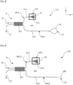
- a photonic sensor C31 according to a first variant of a third embodiment is described below with reference to the [ Fig. 8 ].
- the photonic sensor C31 comprises an interferometer I3 having a first arm BR13 and a second arm BR23.
- the first arm BR13 comprises an optical waveguide G13.
- the second arm BR23 comprises an optical waveguide G23.
- the first arm BR13 comprises a coupling device DC3 between a guided propagation mode in the optical waveguide G13 and a free propagation mode in an ambient medium MA.
- the first arm BR13 comprises an optical system SO3 configured to direct said free propagation mode towards said coupling device DC3 between said free propagation mode in the ambient medium and a guided propagation mode in the optical waveguide G13.
- a light wave OL passing through said first arm BR13 makes part of its journey in said ambient medium MA.
- the first arm BR13 can be a measuring arm and the second arm BR23 can be a reference arm.
- the DC3 coupling device can be a diffraction grating.
- the second arm BR23 may have a surface that can be brought into contact with said ambient medium MA and having a functionalization layer allowing the specific fixation of chemical or biological species.
- the G13 optical waveguide can be a planar waveguide.
- the G23 optical waveguide can be a planar waveguide.
- the interferometer I3 may be a Michelson-type interferometer.
- the first arm BR13 comprises a single coupling device DC3 configured to extract a light wave from the optical waveguide G13 and to reinject it into the optical waveguide G13 after reflection by an optical reflector R3 of an optical system SO3, spaced from said coupling device DC3.
- a light wave OL passing through said first arm BR13 thus completes part of its path in said ambient medium MA.
- the DC3 coupling device is intended to achieve coupling between a guided propagation mode in the G13 optical waveguide and a free propagation mode in an ambient medium MA.
- the optical system SO3 is configured to direct said free propagation mode towards said coupling device DC3.
- the second arm BR23 of the I3 interferometer can include a mirror M.
- the mirror M is formed by a loop of the optical waveguide G23, notably located in a planar layer CO3.
- the interferometer I3 may comprise a splitter SE3, implemented for example by means of a multimode interferometer, for separating a light wave OL coming from an input port into a first component directed towards the first arm BR13 and a second component directed towards the second arm BR23, and for recombining the light waves coming from the first and second arms and directing them towards an output port.
- a splitter SE3 implemented for example by means of a multimode interferometer, for separating a light wave OL coming from an input port into a first component directed towards the first arm BR13 and a second component directed towards the second arm BR23, and for recombining the light waves coming from the first and second arms and directing them towards an output port.
- a photonic sensor C32 according to a second variant of the third embodiment is described below with reference to the [ Fig. 9 ]. Common elements with those of the first variant of the third embodiment are designated by the same references.
- the mirror M comprises a Bragg mirror MB, notably formed by an alternation of materials with different refractive indices, separated by flat surfaces.
- a photonic sensor C33 according to a third variant of the third embodiment is described below with reference to the [ Fig. 10 ]. Elements common to those of the first and second variants of the third embodiment are designated by the same references.
- the interferometer I3 comprises a circulator CI3 instead of the separator SE3 produced by means of a multimode interferometer.
- the circulator CI3 has lower losses than a multimode interferometer, but its production - particularly integrated - is more complex.
- the mirror M can be formed by a loop of the optical waveguide G23, in particular located in a planar layer CO3.
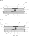
- a first variant of the first arm BR13 of an interferometer I3 of a photonic sensor C311 according to the third embodiment of the invention is described below with reference to the [ Fig. 11 ].
- the optical waveguide G13 of the first arm BR13 of the photonic sensor C311 is for example arranged on a substrate S3.
- the G13 optical waveguide can be formed in a CO3 planar layer.
- the planar layer CO3 may comprise a stack of a first layer CO13 and a second layer CO23.
- the first layer CO13 is for example made of silicon.
- the second layer CO22 may comprise at least one dielectric material, for example silicon oxide.
- the optical waveguide G13 may be located in the second layer CO23.
- the optical reflector R3 may comprise a mirror, for example planar.
- the optical reflector R3 comprises a reflective face F311 opposite the optical waveguide G13.
- the optical reflector R3 and the optical waveguide G13 are for example separated by a distance d.
- the distance d is for example of the order of 150 micrometers.
- the optical reflector R3 can be formed in a planar layer delimiting with the optical waveguide G13 a microchannel for the ambient medium MA.
- the DC3 coupling device may comprise an RD311 diffraction grating.
- the diffraction grating RD311 is in particular configured to diffract the light wave propagating in the waveguide in a direction perpendicular to the free face of the latter perpendicular to the X, Y plane.
- a second variant of the first arm BR13 of an interferometer I3 of a photonic sensor C312 according to the third embodiment of the invention is described below with reference to the [ Fig. 12 ]. Elements in common with those of the variant described with reference to the [ Fig. 11 ] are designated by the same references.
- the optical system SO3 may include a converging lens L312.
- the converging lens L312 is intended to focus or collimate the light wave OL.
- the L312 converging lens for example, is an aspherical lens.
- a third variant of the first arm BR13 of an interferometer I3 of a photonic sensor C313 according to the third embodiment of the invention is described below with reference to the [ Fig. 13 ]. Elements in common with those of the variants described with reference to [ Fig. 11 ] And [ Fig. 12 ] are designated by the same references.
- the optical system SO3 may include a converging lens L313.
- the converging lens L313 is intended to focus or collimate the light wave OL.
- the L313 converging lens is, for example, a converging lens of any shape.
- the shape of the L313 converging lens can be chosen depending on the DC3 coupling device.
- the DC3 coupling device may comprise an RD313 diffraction grating.
- the RD313 diffraction grating and the L313 converging lens can be configured so that the light extracted from the G13 optical waveguide propagates perpendicularly or substantially perpendicularly to the (X, Y) plane, even if the RD313 diffraction grating is configured to diffract a light wave propagating in the one guide in a direction which is not perpendicular to the (X, Y) plane.
- the reflective face F311 of the optical reflector R3 may be at least partially covered with a reflective layer or a reflective coating or a reflective thin film CR3.
- the reflective layer CR3 may comprise at least one metallic material, for example gold.
- the reflective layer CR3 may be located opposite the coupling device DC3.
- the second arm of the interferometer is isolated from the ambient medium, for example by an oxide layer.
- the interferometric signal therefore makes it possible to determine the optical volume index of the ambient medium.
- a prior art Mach-Zehnder interferometer serving as a biosensor and having a 1 cm long sensitive arm has a bulk limit of detection (LoD) of the order of 1 ⁇ 10 -6 RIU.
Landscapes
- Physics & Mathematics (AREA)
- Nonlinear Science (AREA)
- General Physics & Mathematics (AREA)
- Chemical & Material Sciences (AREA)
- Optics & Photonics (AREA)
- Immunology (AREA)
- General Health & Medical Sciences (AREA)
- Biochemistry (AREA)
- Analytical Chemistry (AREA)
- Pathology (AREA)
- Life Sciences & Earth Sciences (AREA)
- Health & Medical Sciences (AREA)
- Engineering & Computer Science (AREA)
- Chemical Kinetics & Catalysis (AREA)
- Plasma & Fusion (AREA)
- Optical Integrated Circuits (AREA)
- Investigating Or Analysing Materials By Optical Means (AREA)
Applications Claiming Priority (1)
| Application Number | Priority Date | Filing Date | Title |
|---|---|---|---|
| FR2310341A FR3153660B1 (fr) | 2023-09-28 | 2023-09-28 | Capteur photonique interférométrique |
Publications (2)
| Publication Number | Publication Date |
|---|---|
| EP4530609A1 true EP4530609A1 (de) | 2025-04-02 |
| EP4530609B1 EP4530609B1 (de) | 2026-07-01 |
Family
ID=89767035
Family Applications (1)
| Application Number | Title | Priority Date | Filing Date |
|---|---|---|---|
| EP24198334.5A Active EP4530609B1 (de) | 2023-09-28 | 2024-09-04 | Interferometrischer photonischer sensor |
Country Status (3)
| Country | Link |
|---|---|
| US (1) | US20250110379A1 (de) |
| EP (1) | EP4530609B1 (de) |
| FR (1) | FR3153660B1 (de) |
Families Citing this family (1)
| Publication number | Priority date | Publication date | Assignee | Title |
|---|---|---|---|---|
| US20250305944A1 (en) * | 2024-03-28 | 2025-10-02 | Applied Materials, Inc. | Optimized mirror-based light focusing for optical sensor assembly |
Citations (3)
| Publication number | Priority date | Publication date | Assignee | Title |
|---|---|---|---|---|
| US20070076212A1 (en) | 2005-09-30 | 2007-04-05 | Zuluaga Andres F | Detecting vulnerable plaque |
| JP2018066664A (ja) | 2016-10-20 | 2018-04-26 | 国立大学法人 東京大学 | 分光分析装置 |
| EP4016053A1 (de) * | 2020-12-21 | 2022-06-22 | Commissariat à l'énergie atomique et aux énergies alternatives | Optische komponente für eine interferometrische bildgebungsvorrichtung |
-
2023
- 2023-09-28 FR FR2310341A patent/FR3153660B1/fr active Active
-
2024
- 2024-08-27 US US18/816,989 patent/US20250110379A1/en active Pending
- 2024-09-04 EP EP24198334.5A patent/EP4530609B1/de active Active
Patent Citations (3)
| Publication number | Priority date | Publication date | Assignee | Title |
|---|---|---|---|---|
| US20070076212A1 (en) | 2005-09-30 | 2007-04-05 | Zuluaga Andres F | Detecting vulnerable plaque |
| JP2018066664A (ja) | 2016-10-20 | 2018-04-26 | 国立大学法人 東京大学 | 分光分析装置 |
| EP4016053A1 (de) * | 2020-12-21 | 2022-06-22 | Commissariat à l'énergie atomique et aux énergies alternatives | Optische komponente für eine interferometrische bildgebungsvorrichtung |
Non-Patent Citations (7)
| Title |
|---|
| BRADLEY VISSER ET AL: "A single-beam photothermal interferometer for in-situ measurements of aerosol light absorption", ATMOS. MEAS. TECH. DISCUSS., 3 July 2020 (2020-07-03), XP055722221, Retrieved from the Internet <URL:https://amt.copernicus.org/preprints/amt-2020-242/amt-2020-242.pdf> [retrieved on 20200813], DOI: 10.5194/amt-2020-242 * |
| D. IGNATEYEVA ET AL.: "Sensing of Surface and Bulk Refractive Index Using Magnetophotonic Crystal with HybridMagneto-Optical Response", SENSORS, vol. 2021, 1984, pages 21 |
| L. LAPLATINE ET AL.: "Silicon photonic olfactory sensor based on an array of 64 biofunctionalized Mach-Zender interferometers", OPTICS EXPRESS, vol. 30, no. 19, 12 September 2022 (2022-09-12), XP093029290, DOI: 10.1364/OE.461858 |
| M. MALINAUSKAS: "3D microoptical elements formed in a photostructurable germaniumsilicate by direct laser writing", OPTICS AND LASERS IN ENGINEERING, vol. 50, 2012, pages 1785 - 1788 |
| P.-I. DIETRICH ET AL.: "In situ 3D nanoprinting of free-form coupling elements for hybrid photonic integration", NATURE PHOTONICS, vol. 12, April 2018 (2018-04-01), pages 241 - 247, XP036468794, DOI: 10.1038/s41566-018-0133-4 |
| R. KARLSSON ET AL.: "Surface plasmon resonance detection and multispot sensing for direct monitoring of interactions involving low-molecular-weight analytes and for determination of low affinities", ANALYTICAL BIOCHEMISTRY, vol. 228, no. 2, 1995, pages 274 - 280, XP002319706, DOI: 10.1006/abio.1995.1350 |
| Z. ZHANG ET AL.: "High-efficiency apodized bidirectional grating coupler for perfectly vertical coupling", OPTICS LETTERS, vol. 44, no. 20, 15 October 2019 (2019-10-15) |
Also Published As
| Publication number | Publication date |
|---|---|
| FR3153660B1 (fr) | 2025-10-10 |
| FR3153660A1 (fr) | 2025-04-04 |
| EP4530609B1 (de) | 2026-07-01 |
| US20250110379A1 (en) | 2025-04-03 |
Similar Documents
| Publication | Publication Date | Title |
|---|---|---|
| US7446880B2 (en) | Method and apparatus for measuring and monitoring optical properties based on a ring-resonator | |
| EP0205236B1 (de) | Messfühler für biologische Moleküle mit Verwendung optischer Wellenleiter | |
| EP0367675B1 (de) | Integrierte Optikvorrichtung zur Messung des Brechungsindex einer Flüssigkeit | |
| US5229833A (en) | Optical sensor | |
| EP1121583B1 (de) | Optischer sensor mit gestapelten dielektrischen schichten | |
| US5647030A (en) | Fiber optic sensor and methods and apparatus relating thereto | |
| US4815843A (en) | Optical sensor for selective detection of substances and/or for the detection of refractive index changes in gaseous, liquid, solid and porous samples | |
| US6738141B1 (en) | Surface plasmon resonance sensor | |
| US6330062B1 (en) | Fourier transform surface plasmon resonance adsorption sensor instrument | |
| US5606633A (en) | Chemical detector employing surface plasmon resonance excited using an optical waveguide configured as an asymmetric waveguide coupler | |
| US7189362B2 (en) | Optical waveguide microcantilever with differential output and associated methods of cantilever sensing | |
| US6330387B1 (en) | Coupled plasmon-waveguide resonance spectroscopic device and method for measuring film properties in the ultraviolet and infrared spectral ranges | |
| JPWO2005078415A1 (ja) | 表面プラズモン共鳴センサー | |
| CA2409486A1 (en) | Coupled plasmon-waveguide resonance spectroscopic device | |
| FR2613826A1 (fr) | Capteur de deplacement en optique integree | |
| CN104792731B (zh) | 一种基于共振光隧穿效应的液体折射率传感器 | |
| WO2018078404A1 (en) | Photonic chips with one sided optical ports self aligned to bifurcated fibers for the label free detection of biolomecular reactions through the use of integrated interferometers and resonators | |
| FR3153660A1 (fr) | Capteur photonique interférométrique | |
| JP2003139694A (ja) | 測定プレート | |
| EP4575463B1 (de) | Gerät zur messung des brechungsindex einer flüssigkeit | |
| Jorgenson | Surface plasmon resonance-based bulk optic and fiber-optic sensors | |
| Foster et al. | Surface plasmon resonance biosensor miniaturization | |
| CN111208060A (zh) | 传感芯片及其制备方法、检测系统和检测方法 | |
| JP2003322616A (ja) | 屈折率測定法及びそれを用いた屈折率測定装置 | |
| Beam et al. | Planar fiber-optic chips for broadband spectroscopic interrogation of thin films |
Legal Events
| Date | Code | Title | Description |
|---|---|---|---|
| PUAI | Public reference made under article 153(3) epc to a published international application that has entered the european phase |
Free format text: ORIGINAL CODE: 0009012 |
|
| STAA | Information on the status of an ep patent application or granted ep patent |
Free format text: STATUS: REQUEST FOR EXAMINATION WAS MADE |
|
| 17P | Request for examination filed |
Effective date: 20240904 |
|
| AK | Designated contracting states |
Kind code of ref document: A1 Designated state(s): AL AT BE BG CH CY CZ DE DK EE ES FI FR GB GR HR HU IE IS IT LI LT LU LV MC ME MK MT NL NO PL PT RO RS SE SI SK SM TR |
|
| GRAP | Despatch of communication of intention to grant a patent |
Free format text: ORIGINAL CODE: EPIDOSNIGR1 |
|
| STAA | Information on the status of an ep patent application or granted ep patent |
Free format text: STATUS: GRANT OF PATENT IS INTENDED |
|
| RIC1 | Information provided on ipc code assigned before grant |
Ipc: G01N 21/45 20060101AFI20260126BHEP Ipc: G01B 9/02015 20220101ALI20260126BHEP Ipc: G02B 6/12 20060101ALN20260126BHEP Ipc: G01N 21/77 20060101ALN20260126BHEP |
|
| INTG | Intention to grant announced |
Effective date: 20260204 |
|
| GRAS | Grant fee paid |
Free format text: ORIGINAL CODE: EPIDOSNIGR3 |
|
| GRAA | (expected) grant |
Free format text: ORIGINAL CODE: 0009210 |
|
| STAA | Information on the status of an ep patent application or granted ep patent |
Free format text: STATUS: THE PATENT HAS BEEN GRANTED |
|
| AK | Designated contracting states |
Kind code of ref document: B1 Designated state(s): AL AT BE BG CH CY CZ DE DK EE ES FI FR GB GR HR HU IE IS IT LI LT LU LV MC ME MK MT NL NO PL PT RO RS SE SI SK SM TR |
|
| REG | Reference to a national code |
Ref country code: CH Ref legal event code: F10 Free format text: ST27 STATUS EVENT CODE: U-0-0-F10-F00 (AS PROVIDED BY THE NATIONAL OFFICE) Effective date: 20260701 Ref country code: GB Ref legal event code: FG4D Free format text: NOT ENGLISH |
|
| REG | Reference to a national code |
Ref country code: DE Ref legal event code: R096 Ref document number: 602024005792 Country of ref document: DE |
|
| REG | Reference to a national code |
Ref country code: IE Ref legal event code: FG4D Free format text: LANGUAGE OF EP DOCUMENT: FRENCH |