EP4530593A1 - Drucksensor mit flansch - Google Patents
Drucksensor mit flansch Download PDFInfo
- Publication number
- EP4530593A1 EP4530593A1 EP24201006.4A EP24201006A EP4530593A1 EP 4530593 A1 EP4530593 A1 EP 4530593A1 EP 24201006 A EP24201006 A EP 24201006A EP 4530593 A1 EP4530593 A1 EP 4530593A1
- Authority
- EP
- European Patent Office
- Prior art keywords
- substrate
- sensor module
- sensor
- elevated portion
- flange
- Prior art date
- Legal status (The legal status is an assumption and is not a legal conclusion. Google has not performed a legal analysis and makes no representation as to the accuracy of the status listed.)
- Pending
Links
Images








Classifications
-
- G—PHYSICS
- G01—MEASURING; TESTING
- G01L—MEASURING FORCE, STRESS, TORQUE, WORK, MECHANICAL POWER, MECHANICAL EFFICIENCY, OR FLUID PRESSURE
- G01L19/00—Details of, or accessories for, apparatus for measuring steady or quasi-steady pressure of a fluent medium insofar as such details or accessories are not special to particular types of pressure gauges
- G01L19/06—Means for preventing overload or deleterious influence of the measured medium on the measuring device or vice versa
- G01L19/0627—Protection against aggressive medium in general
- G01L19/0654—Protection against aggressive medium in general against moisture or humidity
-
- G—PHYSICS
- G01—MEASURING; TESTING
- G01L—MEASURING FORCE, STRESS, TORQUE, WORK, MECHANICAL POWER, MECHANICAL EFFICIENCY, OR FLUID PRESSURE
- G01L19/00—Details of, or accessories for, apparatus for measuring steady or quasi-steady pressure of a fluent medium insofar as such details or accessories are not special to particular types of pressure gauges
- G01L19/0007—Fluidic connecting means
- G01L19/0038—Fluidic connecting means being part of the housing
-
- G—PHYSICS
- G01—MEASURING; TESTING
- G01L—MEASURING FORCE, STRESS, TORQUE, WORK, MECHANICAL POWER, MECHANICAL EFFICIENCY, OR FLUID PRESSURE
- G01L19/00—Details of, or accessories for, apparatus for measuring steady or quasi-steady pressure of a fluent medium insofar as such details or accessories are not special to particular types of pressure gauges
- G01L19/0061—Electrical connection means
- G01L19/0069—Electrical connection means from the sensor to its support
-
- G—PHYSICS
- G01—MEASURING; TESTING
- G01L—MEASURING FORCE, STRESS, TORQUE, WORK, MECHANICAL POWER, MECHANICAL EFFICIENCY, OR FLUID PRESSURE
- G01L19/00—Details of, or accessories for, apparatus for measuring steady or quasi-steady pressure of a fluent medium insofar as such details or accessories are not special to particular types of pressure gauges
- G01L19/06—Means for preventing overload or deleterious influence of the measured medium on the measuring device or vice versa
- G01L19/0627—Protection against aggressive medium in general
- G01L19/0645—Protection against aggressive medium in general using isolation membranes, specially adapted for protection
-
- G—PHYSICS
- G01—MEASURING; TESTING
- G01L—MEASURING FORCE, STRESS, TORQUE, WORK, MECHANICAL POWER, MECHANICAL EFFICIENCY, OR FLUID PRESSURE
- G01L19/00—Details of, or accessories for, apparatus for measuring steady or quasi-steady pressure of a fluent medium insofar as such details or accessories are not special to particular types of pressure gauges
- G01L19/14—Housings
- G01L19/142—Multiple part housings
- G01L19/143—Two part housings
-
- G—PHYSICS
- G01—MEASURING; TESTING
- G01L—MEASURING FORCE, STRESS, TORQUE, WORK, MECHANICAL POWER, MECHANICAL EFFICIENCY, OR FLUID PRESSURE
- G01L19/00—Details of, or accessories for, apparatus for measuring steady or quasi-steady pressure of a fluent medium insofar as such details or accessories are not special to particular types of pressure gauges
- G01L19/14—Housings
- G01L19/147—Details about the mounting of the sensor to support or covering means
-
- G—PHYSICS
- G01—MEASURING; TESTING
- G01L—MEASURING FORCE, STRESS, TORQUE, WORK, MECHANICAL POWER, MECHANICAL EFFICIENCY, OR FLUID PRESSURE
- G01L19/00—Details of, or accessories for, apparatus for measuring steady or quasi-steady pressure of a fluent medium insofar as such details or accessories are not special to particular types of pressure gauges
- G01L19/14—Housings
- G01L19/148—Details about the circuit board integration, e.g. integrated with the diaphragm surface or encapsulation
Definitions
- the present invention relates to MEMS devices mounted within electronic devices, and more particularly to MEMS pressure sensor modules mounted within electronic devices.
- MEMS Microelectromechanical systems
- MEMS devices are commonly implementing the sensors.
- MEMS sensors can include accelerometers, gyroscopes, microphones, pressure sensors, and other types of sensors.
- the MEMS pressure sensor be waterproof. More particularly, the MEMS pressure sensor may be implemented in a sensor module assembly that is waterproof. Accordingly, the electronic device in which the sensor module is implemented may be submerged in water without damaging the MEMS pressure sensor or circuitry associated with the MEMS pressure sensor.
- a waterproof pressure sensor may have a lid.
- the housing is shaped so that an O-ring may be placed on the lid.
- the O-ring assists in ensuring that the pressure sensor is waterproof.
- application of the O-ring may be performed by hand.
- the thickness of certain components of the sensor module may be quite large in order to accommodate the space utilized for the O-ring position. This introduces additional costs and sources of potential malfunction in the manufacturing process.
- an aim of the invention is provide a MEMS pressure sensor module that is waterproof without implementation of an O-ring.
- the MEMS pressure sensor module is waterproof without implementation of an O-ring.
- the MEMS pressure sensor may be coupled to an ASIC on an organic substrate.
- a lid is placed on the substrate over the MEMS pressure sensor.
- the lid is a unitary piece having a relatively wide flange. The wide flange is glued to the substrate in a manner that effectively seals and waterproofs the MEMS pressure sensor without the use of an O-ring.
- the unitary lid may include a raised central portion coupled to the flange.
- the MEMS pressure sensor is positioned within the raised central portion.
- the raised upper portion has a relatively low profile, as space for an O-ring is not utilized. The result is a MEMS pressure sensor module that can effectively provide waterproofing to the MEMS sensor without costly O-ring assembly.
- FIG. 1 is a block diagram of an electronic device 100 including a sensor module 102 coupled within a housing 104 of the electronic device 100. As will be set forth in more detail below, the configuration of the sensor module provides an effective and efficient waterproofed MEMS sensor.
- the sensor module 102 includes a MEMS sensor 101 and an ASIC 103 coupled to a substrate 106.
- the MEMS sensor 101 is a MEMS pressure sensor.
- the MEMS pressure sensor 101 can generate sensor signals indicative of air pressure, water pressure, or other types of pressure.
- the MEMS pressure sensor can be implemented in a semiconductor die.
- the semiconductor die can undergo various semiconductor processes to pattern and form the components of a pressure sensor from the semiconductor die.
- the semiconductor processes can also provide circuit components within the semiconductor die that assist in the generation and transmission of sensor signals indicative of the pressure being sensed.
- the MEMS pressure sensor 101 includes a flexible layer that acts as a diaphragm. Fluid pressure in the environment of the MEMS sensor causes the diaphragm to deflect, bend, or otherwise move. The displacement of the diaphragm can be sensed. The displacement of the diaphragm can be correlated to the fluid pressure in the environment of the MEMS pressure sensor 101.
- the MEMS pressure sensor 101 is a capacitive sensor and electrodes are formed on the diaphragm and on a substrate or surface separated from the diaphragm by a cavity.
- the capacitance between the electrodes changes based on the distance between the electrodes. Accordingly, displacement of the diaphragm is sensed as a change in capacitance.
- the MEMS pressure sensor 101 is a piezoresistive pressure sensor.
- Piezoresistive elements may be formed directly on the diaphragm or coupled to the diaphragm in a manner that causes flexion or movements of the piezoresistive elements. Displacement of the diaphragm causes the piezoresistive elements to flex or strain. The flexion or strain of the piezoresistive elements result in a change in resistance of the piezoresistive elements. Accordingly, the resistance of the piezoresistive elements can be utilized to determine the fluid pressure in the environment of the MEMS pressure sensor 101. Other types of MEMS pressure sensors can be utilized without departing from the scope of the present disclosure.
- the ASIC 103 is an application specific integrated circuit.
- the ASIC 103 can include analog to digital circuitry that receives analog sensor signals from the MEMS pressure sensor 101 and generates digital sensor signals indicative of the pressure sensed by the MEMS pressure sensor 101.
- the analog circuitry of the ASIC 103 can include an analog-to-digital converter (ADC).
- ADC can receive the analog pressure signals and can perform an analog-to-digital conversion to convert the analog pressure signals to digital signals.
- the analog circuitry of the ASIC may include other types of circuitry that can condition or transform signals received directly from the MEMS sensor 101.
- the digital circuitry of the ASIC 103 can receive the digital sensor signals from the analog circuitry and can process or condition the digital sensor signals.
- the digital circuitry can include digital filters, demodulators, digital signal processing circuitry, control circuitry, or other types of circuitry for processing the digital signals.
- the ASIC 103 can be implemented in a separate integrated circuit die from the MEMS sensor 101.
- the MEMS sensor 101 may be electrically coupled to the ASIC 103 by coupling circuitry.
- the coupling circuitry can include one or more of wire bonds, solder bumps, contact pads, signal traces, or other types of coupling circuitry.
- the ASIC 103 and the MEMS sensor 101 may be implemented in a same integrated circuit die.
- the sensor signals from the MEMS sensor 101 are provided to the ASIC 103 by metal interconnect lines and conductive vias embedded within the integrated circuit die.
- the ASIC 103 and the MEMS sensor 101 may be implemented in a system on-chip.
- the substrate 106 may be an organic substrate.
- the organic substrate can include signal traces or buried signal lines that are electrically coupled to the ASIC 103.
- the electrical coupling can be accomplished by solder bumps, wire bonding, or other types of electrical connection.
- Power can be provided to the ASIC 103 via the signal traces and signal lines.
- the digital sensor data can be output from the ASIC to other components of the electronic device 100 via the signal lines and signal traces in the substrate 106.
- the substrate 106 can include a printed circuit board or other type of substrate without departing from the scope of the present disclosure.
- the substrate 106 may be a ceramic substrate.
- the sensor module 102 includes a unitary lid 108 coupled to the substrate 106.
- the unitary lid 108 is a single integral piece that is coupled to the substrate 106.
- the unitary lid 108 can include stainless steel, aluminum, titanium, or other types of metals.
- the unitary lid 108 can include plastic or other types of material.
- the unitary lid 108 includes an elevated central housing 110.
- the elevated central housing 110 is positioned over the MEMS sensor 101 and the ASIC 103.
- the elevated central housing 110 includes an aperture 114 by which pressure can be applied to the MEMS sensor 101.
- the unitary lid 108 includes a flattened flange 112.
- the flattened flange 112 is directly coupled to the substrate 106.
- the flattened flange 112 is relatively wide.
- the flat flange 112 extends to the edge of the substrate 106, or nearly to an edge of the substrate 106. Because the flange 112 covers a relatively large surface area, the flange 112 can be glued to the substrate 106 in a manner that waterproofs the MEMS sensor 101 and the ASIC 103.
- a sealing gel fills the race central housing 110 to further waterproof the MEMS sensor 101 and the ASIC 103.
- the wide flange 112 effectively seals the sensor module 112 in a waterproof manner, the height of the elevated portion 110 can be relatively low. This is because the wide flange 112 makes it so waterproofing can be accomplished without placing an O-ring around the raised elevated portion 110. If an O-ring is not to be utilized, then the height of the elevated central portion can be reduced. The result is a thinner sensor module 102. Furthermore, because an O-ring is not utilized in the waterproofing, a potentially expensive and malfunction prone aspect of manufacture can be removed.
- the sensor module 102 is coupled to a housing 104 of the electronic device 100.
- the housing can be glued to a top surface of the flange 112 or otherwise coupled to the sensor module 102.
- the electronic device 100 can include a wearable electronic device such as a smart watch, smart glasses, a mobile phone, or other types of electronic devices.
- the electronic device 100 can include an industrial machine, a vehicle, or other types of electronic devices that may benefit from implementation of a sensor module 102 within the electronic device 100.
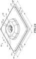
- FIG 2A is a perspective view of a sensor module 102.
- the sensor module 102 of Figure 2A is one example of a sensor module 102 of Figure 1 .
- the sensor module 102 includes a substrate 106.
- the substrate 106 is rectangular and has a first lateral dimension D1 and a second lateral dimension D2.
- the lateral dimension D1 may be equal to the lateral dimension D2 such that the organic substrate 106 is substantially a square shape.
- the lateral dimension D1 can be different than a lateral dimension D2 depending on device specifications.
- the lateral dimensions D1 and D2 are between 3.5 mm and 8 mm, though other dimensions can be utilized without departing from the scope of the present disclosure.
- the substrate 106 includes lateral edges 121.
- the sensor module 102 includes a unitary lid 108.
- the unitary lid 108 includes a raised central housing 110 and the flange 112.
- the race central housing 110 is positioned over a MEMS pressure sensor 101 and an ASIC 103 mounted on the substrate 106.
- the raised central housing 110 has an aperture 114.
- the aperture 114 has a diameter dimension D3.
- the dimension D3 can be less than 1 mm, though other dimensions can be utilized without departing from the scope of the present disclosure.
- the raised central housing 110 also has a height dimension that will be described further below.
- the unitary lid 108 includes a flat flange 112 that extends from the race central portion 110 to the edges of the substrate 106.
- the flat flange 112 has lateral edges 123. When the lid is mounted to the substrate 106, the lateral edges 123 of the flange 112 are very close to the lateral edges 121.
- the width dimension of the flange 112 may be substantially identical to the width dimension of the substrate 106. Alternatively, the width dimensions of the flange 112 may be slightly less than the width dimensions of the substrate 106 such that a lateral separation dimension D4 exists between the edge 123 of the flange 112 and the edge 121 of the substrate 106 when the lid 108 is mounted on the substrate 106.
- the dimension D4 may be between 0.1 mm and 0.3 mm, though other dimensions may be utilized without departing from the scope of the present disclosure.
- the relatively large width of the flange 112 helps ensure waterproofing of the sensor module 102.
- Figure 2B illustrates the relative shape emplacements of the substrate 106 and the flange 112. Furthermore, the top view of Figure 2B illustrates that the flange 112 has rounded corners. Furthermore, the race central housing 110 has rounded corners as well. Alternatively, one or both of the flange 112 and the race central housing 110 can have sharp corners.
- the substrate 106 and the lid 108 can have a circular shape, an elliptical shape, or other shapes without departing from the scope of the present disclosure.
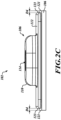
- Figure 2C illustrates the curved nature of the elevated central housing 110 and the flat nature of the flange 112.
- the flange 112 has a substantially flat bottom surface.
- the total height of the elevated central housing above the substrate 106 is between 1 mm and 2 mm, though other heights can be utilized without departing from the scope of the present disclosure.
- the width of the flange 112 from edge to edge may be at least twice as large as the height of the raised central housing 110.
- the width of the flange 112 is more than three times as large as the height of the race central housing 110.
- the relatively large width of the flange helps ensure waterproofing without utilization of an O-ring.
- other ratios of width and height can be utilized.
- Figure 3A shows an intermediate stage of assembly of the sensor module 102.
- the substrate 106 is present.
- a strip of glue 130 is positioned adjacent to the edges of the substrate 106.
- the glue will be utilized for mounting the lid 108 to the substrate 106.
- the substrate 106 includes electrical connectors 132.
- the ASIC 103 has been mounted to the substrate 106 adjacent to the electrical connectors 132.
- the ASIC 103 can include leads, contact pads, or other types of connectors can be utilized to electrically couple the ASIC 103 to the electrical connectors 132.
- a mounting glue 134 has been applied to the top surface of the ASIC 103.
- the mounting will be utilized for hearing the MEMS pressure sensor 101 to the ASIC 103.
- the mounting glue 134 can be placed on the substrate 106 such that the MEMS pressure sensor 101 can be mounted directly to the substrate 106.
- the MEMS sensor 101 has been mounted to the ASIC 103.
- the MEMS sensor 101 has been placed on the glue 134 to adhere the MEMS sensor 101 to the ASIC 103.
- the MEMS sensor 101 is mounted to the substrate 106 by mounting the MEMS sensor 101 to the ASIC 103 that is mounted to the substrate 106.
- Wire bonds extend between electrical connectors (e.g. contact pads) of the MEMS sensor 101 and electrical connectors of the ASIC 103. In this way, the MEMS sensor 101 is electrically coupled to the ASIC 103 such that sensor signals can be passed from the MEMS sensor 101 to the ASIC 103. Wire bonds extend from electrical connectors on the ASIC 103 to the electrical connectors 132 of the substrate 106. Other types of electrical connectors can be utilized without departing from the scope of the present disclosure.
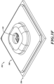
- the unitary lid 108 has been mounted to the substrate 106.
- the bottom surface of the flange 112 has been mounted to the top surface of the substrate 106 via the glue 130.
- Figure 3G is a simplified cross-sectional view of a sensor module 102 after the stage of processing shown in Figure 3F .
- a sealing gel 140 has been placed in the raised central housing 110.
- the sealing gel 140 only partially fills the race central housing 110.
- An annealing or curing process is then performed to cure the sealing gel 140. This part of a waterproofing process.
- a second dose of sealing gel 140 has been placed in the raised central housing 110.
- the second dose of sealing gel 140 fills the remainder of the race central housing 110.
- An annealing or curing process is then performed. Waterproofing of the sensor module 102 is now complete.
- the application in curing of the sealing gel in two separate application steps is highly beneficial. In particular, this process results in either complete or nearly complete lack of air bubbles within the race central housing 110. The presence of air bubbles in the race central housing 110 can be problematic.
- the MEMS pressure sensor 101 senses pressure via the sealing gel 140.
- the fluid pressure causes flexion of the sealing gel 140, which further causes deflection the diaphragm (or other mechanism) within the MEMS sensor 101.
- the gel 140 waterproof the MEMS sensor 101 while still enabling the MEMS sensor 101 to sense pressure.
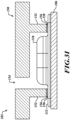
- a housing 150 of the electronic device 100 has been mounted to the flange 112 of the lid 108.
- the flange 112 may include grooves or scoring 158 on the top surface of the flange 112.
- the housing 150 is then mounted to the lid by fixing leg portions 152 on the grooves 158 via a glue 156.
- the housing 150 includes an aperture 154 that allows fluid communication with the MEMS sensor 101.
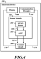
- Figure 4 is a block diagram of the electronic device 100.
- the view of Figure 4 illustrates the generation and passing of signals within the electronic device 100.
- the electronic device 100 comprises, in addition to the sensor module 102, a control circuit 164, a display 166 and communication circuitry 168.
- the MEMS sensor 101 generates sensor signals 160 and passes them to the ASIC 103, as described previously.
- the ASIC 103 receives the sensor signals 160 and generates digital sensor signals 162 by processing and conditioning the sensor signals 160, as described previously.
- the ASIC 103 passes the sensor signals 162 to the control circuit 164.
- the control circuit 164 can correspond to one or more processors of the electronic device 100 not mounted on the substrate 106.
- the ASIC 103 may also include a controller processor.
- the control circuit 164 receives the digital sensor data 162 and may store or process the digital sensor data 162 and provide data 170 to the display 166 or to the communication circuitry 168.
- the display 166 may display data associated with the pressure signals to the user.
- Communication circuitry 168 can include wired or wireless communication circuitry that enables wired or wireless transmission of the data 172 external devices.
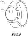
- FIG 5 is an illustration of a smartwatch 170 as one example of an electronic device 100 of Figure 1 or Figure 4 .
- the sensor module 102 shown in dashed lines, is mounted within the smartwatch 170.
- the sensor module 102 may be positioned at a location that enables fluid communication such that the sensor module 102 can sense fluid pressure.
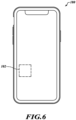
- FIG 6 is an illustration of a smart phone 180as another example of an electronic device 100 of Figure 1 or Figure 4 .
- the sensor module 102 shown in dashed lines, is mounted within the smart phone 180.
- the sensor module 102 may be positioned at a location that enables fluid communication such that the sensor module 102 can sense fluid pressure.
- Figure 7 is a flow diagram of a method 700 for assembling the sensor.
- the method 700 includes mounting a MEMS pressure sensor on an organic or a ceramic substrate.
- the method 700 includes mounting a unitary lid on the organic substrate.
- the unitary lid includes a central elevated portion housing the MEMS pressure sensor, an aperture in the central elevated portion, and a flat flange extending from the central elevated portion to an edge of the organic substrate.
- the method 700 includes partially filling the central elevated portion with a sealing gel.
- the method 700 includes performing a first curing process of the sealing gel.
- the method 700 includes filling a remainder of the central elevated portion with the sealing gel after performing the first curing process.
- the method 700 includes performing a second curing process of the sealing gel.
- Figure 8 is a flow diagram of a method 800, for operating an electronic device
- the method 800 includes generating, with a MEMS pressure sensor coupled to a substrate, analog pressure signals.
- the method 800 includes receiving, with an ASIC electrically coupled to the MEMS pressure sensor, digital pressure signals based on the analog pressure signals.
- the method 800 includes passing the digital pressure signals to a control circuit of an electronic device, wherein the MEMS pressure sensor and the ASIC are positioned within a central elevated portion of a unitary lid mounted on the substrate and including an aperture in the central elevated portion and a flat flange extending from the central elevated portion to an edge of the substrate.
- the invention refers to a sensor module including a substrate, a MEMS pressure sensor mounted to the substrate, and a unitary lid mounted on the substrate.
- the unitary lid includes a central elevated portion housing the MEMS pressure sensor, an aperture in the central elevated portion, and a flat flange extending from the central elevated portion toward an edge of the substrate.
- the sensor module includes an ASIC electrically coupled to the MEMS pressure sensor and mounted on the substrate below the central elevated portion.
- the sensor module includes a sealing gel within central elevated portion.
- the unitary lid is stainless steel.
- the central elevated portion is less than 3 mm in height above the substrate.
- the central aperture is less than 1 mm in diameter.
- the substrate has a rectangular surface having four lateral edges, wherein the unitary flange extends to within 1 mm of each lateral edge.
- the flange has grooves in a top surface.
- the substrate has a circular top surface, wherein the flange has a circular edge.
- a method in one embodiment, includes mounting a MEMS pressure sensor on an substrate and mounting a unitary lid on the substrate.
- the unitary lid includes a central elevated portion housing the MEMS pressure sensor, an aperture in the central elevated portion, and a flat flange extending from the central elevated portion to an edge of the substrate.
- the method includes partially filling the central elevated portion with a sealing gel, performing a first curing process of the sealing gel, filling a remainder of the central elevated portion with the sealing gel after performing the first curing process, and performing a second curing process of the sealing gel.
- mounting the unitary lid to the substrate includes gluing the flange to the substrate.
- the method includes mounting an ASIC to the substrate prior to mounting the unitary lid to the substrate.
- the method includes gluing a housing of an electronic device to a top surface of the flange.
- gluing the housing to the top surface of the flange includes gluing the housing to a grooved portion of the top surface.
- the unitary lid is stainless steel.
- the substrate has a rectangular surface having four lateral edges, wherein the unitary flange extends to within 1 mm of each lateral edge.
- a method includes generating, with a MEMS pressure sensor coupled to a substrate, analog pressure signals, receiving, with an ASIC electrically coupled to the MEMS pressure sensor, digital pressure signals based on the analog pressure signals, and passing the digital pressure signals to a control circuit of an electronic device.
- the MEMS pressure sensor and the ASIC are positioned within a central elevated portion of a unitary lid mounted on the substrate and including an aperture in the central elevated portion and a flat flange extending from the central elevated portion to an edge of the substrate.
- the electronic device is a smart watch.
- the electronic device is a smart phone.
- the sensor model 102 and/or the housing 150 may have different configurations from the ones shown and described herein.
Landscapes
- Physics & Mathematics (AREA)
- General Physics & Mathematics (AREA)
- Chemical & Material Sciences (AREA)
- Analytical Chemistry (AREA)
- Measuring Fluid Pressure (AREA)
Applications Claiming Priority (1)
| Application Number | Priority Date | Filing Date | Title |
|---|---|---|---|
| US18/476,114 US20250102391A1 (en) | 2023-09-27 | 2023-09-27 | Pressure sensor with flange |
Publications (1)
| Publication Number | Publication Date |
|---|---|
| EP4530593A1 true EP4530593A1 (de) | 2025-04-02 |
Family
ID=92843312
Family Applications (1)
| Application Number | Title | Priority Date | Filing Date |
|---|---|---|---|
| EP24201006.4A Pending EP4530593A1 (de) | 2023-09-27 | 2024-09-18 | Drucksensor mit flansch |
Country Status (3)
| Country | Link |
|---|---|
| US (1) | US20250102391A1 (de) |
| EP (1) | EP4530593A1 (de) |
| CN (1) | CN119714664A (de) |
Citations (2)
| Publication number | Priority date | Publication date | Assignee | Title |
|---|---|---|---|---|
| US20180335360A1 (en) * | 2017-05-16 | 2018-11-22 | Honeywell International Inc. | Ported Pressure Sensor With No Internally Trapped Fluid |
| US11397121B2 (en) * | 2017-06-08 | 2022-07-26 | Robert Bosch Gmbh | Micromechanical pressure sensor system and method for manufacturing a micromechanical pressure sensor system |
Family Cites Families (6)
| Publication number | Priority date | Publication date | Assignee | Title |
|---|---|---|---|---|
| US11561144B1 (en) * | 2018-09-27 | 2023-01-24 | Apple Inc. | Wearable electronic device with fluid-based pressure sensing |
| US11839450B2 (en) * | 2020-09-23 | 2023-12-12 | Apple Inc. | Pressure sensor module for wearable applanation tonometer |
| US11397120B2 (en) * | 2020-09-23 | 2022-07-26 | Apple Inc. | Interface pressure sensor system for electronic device |
| DE102020212123A1 (de) * | 2020-09-25 | 2021-12-16 | Robert Bosch Gesellschaft mit beschränkter Haftung | Sensor und Verfahren zur Herstellung eines Sensors |
| CN114636510A (zh) * | 2020-12-15 | 2022-06-17 | 浙江三花汽车零部件有限公司 | 传感器组件以及阀装置 |
| US20230050748A1 (en) * | 2021-08-10 | 2023-02-16 | Nanusens SL | Mems pressure sensor built using the beol metal layers of a solid-state semiconductor process |
-
2023
- 2023-09-27 US US18/476,114 patent/US20250102391A1/en active Pending
-
2024
- 2024-09-18 EP EP24201006.4A patent/EP4530593A1/de active Pending
- 2024-09-25 CN CN202411344489.4A patent/CN119714664A/zh active Pending
Patent Citations (2)
| Publication number | Priority date | Publication date | Assignee | Title |
|---|---|---|---|---|
| US20180335360A1 (en) * | 2017-05-16 | 2018-11-22 | Honeywell International Inc. | Ported Pressure Sensor With No Internally Trapped Fluid |
| US11397121B2 (en) * | 2017-06-08 | 2022-07-26 | Robert Bosch Gmbh | Micromechanical pressure sensor system and method for manufacturing a micromechanical pressure sensor system |
Also Published As
| Publication number | Publication date |
|---|---|
| US20250102391A1 (en) | 2025-03-27 |
| CN119714664A (zh) | 2025-03-28 |
Similar Documents
| Publication | Publication Date | Title |
|---|---|---|
| US8316725B2 (en) | Force sensor | |
| EP3205997B1 (de) | In elastomerem material eingekapselter drucksensor und system mit dem drucksensor | |
| EP1219136B1 (de) | Druckwandler | |
| US6732588B1 (en) | Pressure transducer | |
| US8375799B2 (en) | Increased sensor die adhesion | |
| WO2001019134A3 (en) | Silicon-based sensor system | |
| KR20180025845A (ko) | 지문 인식 모듈 | |
| US10067014B1 (en) | Force sensor | |
| CN209216065U (zh) | 压力传导结构、压力传感器封装结构以及触控装置 | |
| EP4530593A1 (de) | Drucksensor mit flansch | |
| US8866241B2 (en) | Pressure sensing device having contacts opposite a membrane | |
| CN104977121B (zh) | 压力检测装置 | |
| CN207354395U (zh) | 壳体组件及电子装置 | |
| CN210986418U (zh) | 多功能麦克风 | |
| EP4033215B1 (de) | Kostengünstiger umgossener leiterrahmen-kraftsensor mit mehreren montagepositionen | |
| TW202028939A (zh) | 力量感測器 | |
| JP3602238B2 (ja) | 半導体圧力センサおよびその製造方法 | |
| CN216925890U (zh) | 防水气压计 | |
| CN107438855B (zh) | 指纹芯片封装模组、指纹识别模组和封装方法 | |
| CN216925891U (zh) | 防水气压计 | |
| CN210986417U (zh) | 一种多功能麦克风 | |
| US20250140626A1 (en) | Sensor electronic device | |
| JP6476036B2 (ja) | 圧力センサ | |
| CN115360292B (zh) | 一种压电薄膜传感器 | |
| CN207354402U (zh) | 壳体组件和电子装置 |
Legal Events
| Date | Code | Title | Description |
|---|---|---|---|
| PUAI | Public reference made under article 153(3) epc to a published international application that has entered the european phase |
Free format text: ORIGINAL CODE: 0009012 |
|
| STAA | Information on the status of an ep patent application or granted ep patent |
Free format text: STATUS: THE APPLICATION HAS BEEN PUBLISHED |
|
| AK | Designated contracting states |
Kind code of ref document: A1 Designated state(s): AL AT BE BG CH CY CZ DE DK EE ES FI FR GB GR HR HU IE IS IT LI LT LU LV MC ME MK MT NL NO PL PT RO RS SE SI SK SM TR |
|
| STAA | Information on the status of an ep patent application or granted ep patent |
Free format text: STATUS: REQUEST FOR EXAMINATION WAS MADE |
|
| 17P | Request for examination filed |
Effective date: 20251001 |
|
| STAA | Information on the status of an ep patent application or granted ep patent |
Free format text: STATUS: EXAMINATION IS IN PROGRESS |
|
| 17Q | First examination report despatched |
Effective date: 20251210 |