EP4530556A1 - Vorrichtung zur erzeugung von potentialdifferenzen - Google Patents
Vorrichtung zur erzeugung von potentialdifferenzen Download PDFInfo
- Publication number
- EP4530556A1 EP4530556A1 EP23811508.3A EP23811508A EP4530556A1 EP 4530556 A1 EP4530556 A1 EP 4530556A1 EP 23811508 A EP23811508 A EP 23811508A EP 4530556 A1 EP4530556 A1 EP 4530556A1
- Authority
- EP
- European Patent Office
- Prior art keywords
- layer
- nanostructure
- electrode
- hydrogen
- multilayer film
- Prior art date
- Legal status (The legal status is an assumption and is not a legal conclusion. Google has not performed a legal analysis and makes no representation as to the accuracy of the status listed.)
- Pending
Links
Images


Classifications
-
- H—ELECTRICITY
- H01—ELECTRIC ELEMENTS
- H01M—PROCESSES OR MEANS, e.g. BATTERIES, FOR THE DIRECT CONVERSION OF CHEMICAL ENERGY INTO ELECTRICAL ENERGY
- H01M14/00—Electrochemical current or voltage generators not provided for in groups H01M6/00 - H01M12/00; Manufacture thereof
-
- C—CHEMISTRY; METALLURGY
- C01—INORGANIC CHEMISTRY
- C01B—NON-METALLIC ELEMENTS; COMPOUNDS THEREOF; METALLOIDS OR COMPOUNDS THEREOF NOT COVERED BY SUBCLASS C01C
- C01B3/00—Hydrogen; Gaseous mixtures containing hydrogen; Separation of hydrogen from mixtures containing it; Purification of hydrogen; Reversible storage of hydrogen
- C01B3/0005—Reversible storage of hydrogen, e.g. by hydrogen getters or electrodes
- C01B3/001—Reversible storage of hydrogen, e.g. by hydrogen getters or electrodes characterised by the uptaking media; Treatment thereof
- C01B3/0084—Solid storage media characterised by their shape, e.g. porous compacts or hollow particles
-
- H—ELECTRICITY
- H01—ELECTRIC ELEMENTS
- H01M—PROCESSES OR MEANS, e.g. BATTERIES, FOR THE DIRECT CONVERSION OF CHEMICAL ENERGY INTO ELECTRICAL ENERGY
- H01M8/00—Fuel cells; Manufacture thereof
- H01M8/02—Details
- H01M8/0202—Collectors; Separators, e.g. bipolar separators; Interconnectors
- H01M8/023—Porous and characterised by the material
- H01M8/0241—Composites
- H01M8/0245—Composites in the form of layered or coated products
-
- H—ELECTRICITY
- H01—ELECTRIC ELEMENTS
- H01M—PROCESSES OR MEANS, e.g. BATTERIES, FOR THE DIRECT CONVERSION OF CHEMICAL ENERGY INTO ELECTRICAL ENERGY
- H01M8/00—Fuel cells; Manufacture thereof
- H01M8/02—Details
- H01M8/0202—Collectors; Separators, e.g. bipolar separators; Interconnectors
- H01M8/0204—Non-porous and characterised by the material
- H01M8/0206—Metals or alloys
-
- H—ELECTRICITY
- H01—ELECTRIC ELEMENTS
- H01M—PROCESSES OR MEANS, e.g. BATTERIES, FOR THE DIRECT CONVERSION OF CHEMICAL ENERGY INTO ELECTRICAL ENERGY
- H01M8/00—Fuel cells; Manufacture thereof
- H01M8/04—Auxiliary arrangements, e.g. for control of pressure or for circulation of fluids
- H01M8/04007—Auxiliary arrangements, e.g. for control of pressure or for circulation of fluids related to heat exchange
- H01M8/04037—Electrical heating
-
- H—ELECTRICITY
- H01—ELECTRIC ELEMENTS
- H01M—PROCESSES OR MEANS, e.g. BATTERIES, FOR THE DIRECT CONVERSION OF CHEMICAL ENERGY INTO ELECTRICAL ENERGY
- H01M8/00—Fuel cells; Manufacture thereof
- H01M8/04—Auxiliary arrangements, e.g. for control of pressure or for circulation of fluids
- H01M8/04007—Auxiliary arrangements, e.g. for control of pressure or for circulation of fluids related to heat exchange
- H01M8/04067—Heat exchange or temperature measuring elements, thermal insulation, e.g. heat pipes, heat pumps, fins
-
- B—PERFORMING OPERATIONS; TRANSPORTING
- B82—NANOTECHNOLOGY
- B82Y—SPECIFIC USES OR APPLICATIONS OF NANOSTRUCTURES; MEASUREMENT OR ANALYSIS OF NANOSTRUCTURES; MANUFACTURE OR TREATMENT OF NANOSTRUCTURES
- B82Y30/00—Nanotechnology for materials or surface science, e.g. nanocomposites
-
- C—CHEMISTRY; METALLURGY
- C01—INORGANIC CHEMISTRY
- C01B—NON-METALLIC ELEMENTS; COMPOUNDS THEREOF; METALLOIDS OR COMPOUNDS THEREOF NOT COVERED BY SUBCLASS C01C
- C01B3/00—Hydrogen; Gaseous mixtures containing hydrogen; Separation of hydrogen from mixtures containing it; Purification of hydrogen; Reversible storage of hydrogen
- C01B3/0005—Reversible storage of hydrogen, e.g. by hydrogen getters or electrodes
- C01B3/001—Reversible storage of hydrogen, e.g. by hydrogen getters or electrodes characterised by the uptaking media; Treatment thereof
- C01B3/0018—Inorganic elements or compounds, e.g. oxides, nitrides, borohydrides or zeolites; Solutions thereof
- C01B3/0026—Metals or metal hydrides
-
- C—CHEMISTRY; METALLURGY
- C01—INORGANIC CHEMISTRY
- C01B—NON-METALLIC ELEMENTS; COMPOUNDS THEREOF; METALLOIDS OR COMPOUNDS THEREOF NOT COVERED BY SUBCLASS C01C
- C01B3/00—Hydrogen; Gaseous mixtures containing hydrogen; Separation of hydrogen from mixtures containing it; Purification of hydrogen; Reversible storage of hydrogen
- C01B3/0005—Reversible storage of hydrogen, e.g. by hydrogen getters or electrodes
- C01B3/001—Reversible storage of hydrogen, e.g. by hydrogen getters or electrodes characterised by the uptaking media; Treatment thereof
- C01B3/0018—Inorganic elements or compounds, e.g. oxides, nitrides, borohydrides or zeolites; Solutions thereof
- C01B3/0031—Intermetallic compounds; Metal alloys
-
- F—MECHANICAL ENGINEERING; LIGHTING; HEATING; WEAPONS; BLASTING
- F24—HEATING; RANGES; VENTILATING
- F24V—COLLECTION, PRODUCTION OR USE OF HEAT NOT OTHERWISE PROVIDED FOR
- F24V30/00—Apparatus or devices using heat produced by exothermal chemical reactions other than combustion
-
- H—ELECTRICITY
- H01—ELECTRIC ELEMENTS
- H01M—PROCESSES OR MEANS, e.g. BATTERIES, FOR THE DIRECT CONVERSION OF CHEMICAL ENERGY INTO ELECTRICAL ENERGY
- H01M8/00—Fuel cells; Manufacture thereof
-
- Y—GENERAL TAGGING OF NEW TECHNOLOGICAL DEVELOPMENTS; GENERAL TAGGING OF CROSS-SECTIONAL TECHNOLOGIES SPANNING OVER SEVERAL SECTIONS OF THE IPC; TECHNICAL SUBJECTS COVERED BY FORMER USPC CROSS-REFERENCE ART COLLECTIONS [XRACs] AND DIGESTS
- Y02—TECHNOLOGIES OR APPLICATIONS FOR MITIGATION OR ADAPTATION AGAINST CLIMATE CHANGE
- Y02E—REDUCTION OF GREENHOUSE GAS [GHG] EMISSIONS, RELATED TO ENERGY GENERATION, TRANSMISSION OR DISTRIBUTION
- Y02E60/00—Enabling technologies; Technologies with a potential or indirect contribution to GHG emissions mitigation
- Y02E60/10—Energy storage using batteries
Definitions
- the present invention relates to a potential difference generation device having a nanostructure in which a first layer and a second layer are stacked, each layer being made of different hydrogen storage metals and having a nano-sized thickness (less than 1000 nm).
- the inventors of the present application have previously proposed a heat generating device including a heat generating element including a base made of a hydrogen storage metal or the like and a multilayer film formed on a surface of the base (see Patent Literature 1).
- the multilayer film has a configuration in which a first layer made of a hydrogen storage metal or the like and having a thickness of less than 1000 nm and a second layer made of a hydrogen storage metal or the like different from that of the first layer and having a thickness of less than 1000 nm are stacked, and a heterogeneous material interface is formed between the first layer and the second layer.
- Non-Patent Literature 1 A. Kitamura, A. Takahashi, K. Takahashi, R. Seto, T. Hatano, Y. Iwamura, T. Itoh, J. Kasagi, M. Nakamura, M. Uchimura, H. Takahashi, S. Sumitomo, T. Hioki, T. Motohiro, Y. Furuyama, M. Kishida, H. Matsune, "Excess heat evolution from nanocomposite samples under exposure to hydrogen isotope gases", International Journal of Hydrogen Energy 43 (2016) 16187-16200 .
- Patent Literature 1 WO2018/230447
- Heat generated by the heat generating element of Patent Literature 1 can be converted into electric power by using, for example, a turbine for utilization.
- a turbine for utilization there is a problem in that heat loss occurs when converting heat into electric power. Therefore, development of a novel electric power generating device that can generate electric power directly without using heat is desired.
- the present invention has been made based on this new finding, and an object thereof is to provide a potential difference generation device that can generate electric power directly.
- the potential difference generation device of the present invention includes: a nanostructure including a base made of a hydrogen storage metal, a hydrogen storage alloy, or a proton conductor, and a multilayer film provided on the base; a first electrode provided on the nanostructure; and a second electrode provided to face the multilayer film, in which the multilayer film has a configuration in which a first layer made of a hydrogen storage metal or a hydrogen storage alloy and having a thickness of less than 1000 nm and a second layer made of a hydrogen storage metal or a hydrogen storage alloy different from that of the first layer or made of ceramics and having a thickness of less than 1000 nm are stacked, and a heterogeneous material interface is formed between the first layer and the second layer, the nanostructure is heated, so that hydrogen permeates through or diffuses into the heterogeneous material interface by quantum diffusion, and a charged particle is emitted from the multilayer film, and the charged particle is captured by the second electrode, so that a potential difference is generated between the first electrode and the second electrode.
- a potential difference generation device that can generate electric power directly by occluding hydrogen into a nanostructure made of a hydrogen storage metal or the like and causing quantum diffusion of hydrogen can be provided.
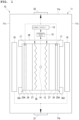
- a potential difference generation device 10 includes a container 11, a heater 12, a power supply 13, a temperature sensor 14, a control unit 15, a nanostructure 16A, a first electrode 17, and a second electrode 18.
- the potential difference generation device 10 is configured such that the nanostructure 16A occludes hydrogen and is heated by the heater 12, so that a charged particle emitted during quantum diffusion of hydrogen is captured, and a potential difference is generated between the first electrode 17 and the second electrode 18.
- a load such as various electrical devices driven by electric power between the first electrode 17 and the second electrode 18, a current caused by the potential difference flows in the load.
- the “potential difference generation device” is a novel electric power generating device that can generate electric power directly by occluding hydrogen into a nanostructure in which a first layer and a second layer are stacked, each layer being made of different hydrogen storage metals or the like and having a nano-sized thickness (less than 1000 nm), and then causing quantum diffusion of hydrogen at a heterogeneous material interface formed between the first layer and the second layer, and is also referred to as a "quantum hydrogen battery”.
- a detailed configuration of the potential difference generation device 10 will be described below.
- the container 11 is a hollow container having an upper portion 11a, a bottom portion 11b, and a side portion 11c. At least one of the upper portion 11a and the bottom portion 11b of the container 11 is detachable from the side portion 11c, and the container 11 is sealed by attaching the upper portion 11a and the bottom portion 11b to the side portion 11c.
- the heater 12, the power supply 13, the temperature sensor 14, the control unit 15, the nanostructure 16A, the first electrode 17, and the second electrode 18 are housed inside the container 11, but the power supply 13 and the control unit 15 may be provided outside the container 11.
- a pressure sensor (not shown) that detects an internal pressure of the container 11 is provided inside the container 11.
- the inside of the container 11 is evacuated by using a vacuum generating device (not shown) such as a vacuum pump.
- a hydrogen-based gas is introduced into the container 11 by using a hydrogen introduction device (not shown) such as a hydrogen tank that stores the hydrogen-based gas.
- the hydrogen-based gas refers to a gas that contains isotopes of hydrogen.
- As the hydrogen-based gas at least one of a deuterium gas and a protium gas is used.
- the protium gas includes a mixture of naturally occurring protium and deuterium, that is, a mixture in which an abundance ratio of protium is 99.985% and an abundance ratio of deuterium is 0.015%. In the following description, when there is no need to distinguish between protium and deuterium, a description of "hydrogen" is made.
- the container 11 includes a positive terminal 21 and a negative terminal 22.
- the negative terminal 22 is provided on the upper portion 11a
- the positive terminal 21 is provided at the bottom portion 11b, but positions of the positive terminal 21 and the negative terminal 22 are not particularly limited and can be designed as appropriate.
- the container 11 is made of a material having heat resistance and pressure resistance, such as carbon steel, austenitic stainless steel, heat-resistant non-ferrous alloy steel, or a material that reflects radiant heat, such as Ni, Cu, or Mo.
- a shape of the container 11 is not particularly limited, and may be a cylindrical shape, an elliptical cylindrical shape, a rectangular cylindrical shape, or the like.
- the heater 12 increases a temperature in response to the supplied electric power, and heats the nanostructure 16A.
- the heater 12 is a plate-like ceramic heater having a configuration in which a conductor is provided inside a base made of ceramics.
- the power supply 13 is electrically connected to the heater 12 and supplies electric power to the heater 12.
- the temperature sensor 14 detects a temperature of the nanostructure 16A.
- the temperature sensor 14 is a thermocouple built into the heater 12 and is configured to detect the temperature of the nanostructure 16A via the heater 12.
- the control unit 15 is electrically connected to the power supply 13 and the temperature sensor 14, and controls an output of the power supply 13 based on a detection result of the temperature sensor 14 to set the nanostructure 16A to a desired temperature.
- the nanostructure 16A includes a base 24 made of a hydrogen storage metal, a hydrogen storage alloy, or a proton conductor, and a multilayer film 25A (also referred to as a nanostructure film) provided on the base 24.
- a base 24 made of a hydrogen storage metal, a hydrogen storage alloy, or a proton conductor
- a multilayer film 25A also referred to as a nanostructure film
- the multilayer film 25A is provided on one surface of the base 24, but the multilayer film 25A may be provided on both surfaces of the base 24.
- the nanostructure 16A is a plate-like member.
- the nanostructure 16A is provided on both surfaces of the heater 12 via a shielding plate 27.
- One surface of the shielding plate 27 is in contact with the base 24 of the nanostructure 16A, and the other surface of the shielding plate 27 is in contact with the heater 12.
- the shielding plate 27 is, for example, a SiO 2 plate.
- the nanostructure 16A is integrated with the heater 12 and the shielding plate 27 by a holder 28.
- the holder 28 holds the nanostructure 16A such that a surface of the multilayer film 25A of the nanostructure 16A (surface opposite to the base 24 in Fig. 1 ) is exposed.
- the holder 28 is made of, for example, ceramics.
- the first electrode 17 is provided on the nanostructure 16A.
- the first electrode 17 is provided on the base 24 of the nanostructure 16A.
- the first electrode 17 is electrically connected to the negative terminal 22.
- the first electrode 17 is made of a material that has electrical conductivity, heat resistance, and pressure resistance. Examples of the material for the first electrode 17 include nickel (Ni), palladium (Pd), vanadium (V), titanium (Ti), niobium (Nb), iron (Fe), molybdenum (Mo), platinum (Pt), zirconium (Zr), tantalum (Ta), tungsten (W), and alloys based on these metals.
- the second electrode 18 is provided to face the multilayer film 25A.
- the second electrode 18 is arranged with a predetermined gap in a direction perpendicular to the surface of the multilayer film 25A (left-right direction of paper in Fig. 1 ).
- the second electrode 18 is supported by a support member (not shown) fixed to an inner wall of the container 11.
- the second electrode 18 is electrically connected to the positive terminal 21.
- the second electrode 18 is made of a material that has electrical conductivity, heat resistance, and pressure resistance, and can capture a charged particle emitted from the surface of the multilayer film 25A (described later).
- Examples of the material for the second electrode 18 include nickel (Ni), palladium (Pd), gold (Au), silver (Ag), copper (Cu), aluminum (Al), iron (Fe), molybdenum (Mo), platinum (Pt), tantalum (Ta), tungsten (W), and alloys based on these metals.
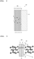
- a configuration of the nanostructure 16A will be described in detail with reference to Fig. 2 .
- Examples of hydrogen storage metals include Ni, Pd, V, Nb, Ta, and Ti.
- Examples of the hydrogen storage alloy include LaNi 5 , CaCu 5 , MgZn 2 , ZrNi 2 , ZrCr 2 , TiFe, TiCo, Mg 2 Ni, and Mg 2 Cu.
- Examples of the proton conductor include a BaCeO 3 -based conductor (for example, Ba(Ce 0.95 Y 0.05 )O 3- ⁇ ), a SrCeO 3 -based conductor (for example, Sr(Ce 0.95 Y 0.05 )O 3- ⁇ ), a CaZrO 3 -based conductor (for example, CaZr 0.95 Y 0.05 O 3- ⁇ ), a SrZrO 3 -based conductor (for example, SrZr 0.9 Y 0.1 O 3- ⁇ ), ⁇ Al 2 O 3 , and ⁇ Ga 2 O 3 .
- the base 24 may be implemented by a porous body or a hydrogen permeable film.
- the porous body has pores having a size through which the hydrogen-based gas can pass.
- the porous body is made of, for example, a metal, a non-metal, or ceramics.
- the porous body is preferably made of a material that does not hinder a reaction between the hydrogen-based gas and the multilayer film 25A.
- the hydrogen permeable film is made of, for example, a hydrogen storage metal or a hydrogen storage alloy.
- the hydrogen permeable film is a film having a mesh-like sheet.
- the second layer 32 is made of, for example, any one of Ni, Pd, Cu, Mn, Cr, Fe, Mg, Co, an alloy thereof, and SiC.
- An alloy for forming the second layer 32 is preferably an alloy made of two or more of Ni, Pd, Cu, Mn, Cr, Fe, Mg, and Co.
- the alloy for forming the second layer 32 may be an alloy obtained by adding an additive element to Ni, Pd, Cu, Mn, Cr, Fe, Mg, and Co.
- a combination of the first layer 31 and the second layer 32 is preferably Pd-Ni, Ni-Cu, Ni-Cr, Ni-Fe, Ni-Mg, and Ni-Co when types of elements are expressed as "first layer 31-second layer 32".
- first layer 31-second layer 32 is preferably Ni-SiC.
- the hydrogen-based gas When the hydrogen-based gas is supplied to the nanostructure 16A, hydrogen is densely occluded in the base 24 and the multilayer film 25A of the nanostructure 16A. Even if the supply of the hydrogen-based gas is stopped, the nanostructure 16A can maintain a state in which hydrogen is occluded in the base 24 and the multilayer film 25A.
- the nanostructure 16A When the nanostructure 16A is heated, the hydrogen occluded in the base 24 and the multilayer film 25A hops in a manner of quantum diffusion. It is known that hydrogen is light and hops in a manner of quantum diffusion in hydrogen-occupied sites (octahedral sites or tetrahedral sites) of substance A and substance B.
- the charged particles CP are positively charged ions.
- the charged particles CP are considered to be those in which atomic nuclei of the elements (Ni, Cu, or the like) constituting the nanostructure 16A are ejected.
- the charged particles CP emitted from the multilayer film 25A are captured by the second electrode 18 (see Fig. 1 ) that is provided to face the multilayer film 25A.
- the second electrode 18 that captures the charged particles CP has a positive potential
- the first electrode 17 provided on the base 24 of the nanostructure 16A has a negative potential
- a potential difference is generated between the first electrode 17 and the second electrode 18.
- excess heat By heating the nanostructure 16A, hydrogen penetrates through or diffuses into the heterogeneous material interface 36 by quantum diffusion, heat (hereinafter, referred to as excess heat) having a temperature equal to or higher than a temperature at which the nanostructure 16A is heated is generated.
- the nanostructure 16A includes the base 24 and the multilayer film 25A, but is not limited thereto.
- the multilayer film 25B has a configuration in which the first layer 31, the second layer 32, and a third layer 33 made of a hydrogen storage metal, a hydrogen storage alloy, or ceramics different from those of the first layer 31 and the second layer 32 and having a thickness of less than 1000 nm are stacked, and a heterogeneous material interface 37 is formed between the first layer 31 and the third layer 33.
- the third layer 33 is made of, for example, any one of Ni, Pd, Cu, Cr, Fe, Mg, Co, an alloy thereof, SiC, CaO, Y 2 O 3 , TiC, LaB 6 , SrO, and BaO.
- An alloy for forming the third layer 33 is preferably an alloy made of two or more of Ni, Pd, Cu, Cr, Fe, Mg, and Co.
- the alloy for forming the third layer 33 may be an alloy obtained by adding an additive element to Ni, Pd, Cu, Cr, Fe, Mg, and Co.
- the third layer 33 is preferably made of any one of CaO, Y 2 O 3 , TiC, LaB 6 , SrO, and BaO.
- an occluding amount of hydrogen is increased, an amount of hydrogen permeating through the heterogeneous material interface 36 and the heterogeneous material interface 37 is increased, an emission amount of charged particles CP increases, and a high output of excess heat can be achieved.
- a combination of the first layer 31, the second layer 32, and the third layer 33 is preferably Pd-CaO-Ni, Pd-Y 2 O 3 -Ni, Pd-TiC-Ni, Pd-LaB 6 -Ni, Ni-CaO-Cu, Ni-Y 2 O 3 -Cu, Ni-TiC-Cu, Ni-LaB 6 -Cu, Ni-Co-Cu, Ni-CaO-Cr, Ni-Y 2 O 3 -Cr, Ni-TiC-Cr, Ni-LaB 6 -Cr, Ni-CaO-Fe, Ni-Y 2 O 3 -Fe, Ni-TiC-Fe, Ni-LaB 6 -Fe, Ni-Cr-Fe, Ni-CaO-Mg, Ni-Y 2 O 3 -Mg, Ni-TiC-Mg, Ni-LaB 6 -Mg, Ni-CaO-Co, Ni-Y 2 O 3 -Co, Ni-TiC-Co
- the nanostructure 16B By heating the nanostructure 16B, hydrogen penetrates through or diffuses into the heterogeneous material interface 36 and the heterogeneous material interface 37 by quantum diffusion, the charged particles CP are emitted from the multilayer film 25B, and the excess heat is generated.
- the nanostructure 16B can be manufactured by a method same as the method for manufacturing the nanostructure 16A.
- the potential difference generation device 10 may include the nanostructure 16B instead of the nanostructure 16A.
- Fig. 5 is a cross-sectional view showing a configuration of yet another nanostructure 16C.
- the nanostructure 16C includes the base 24 and a multilayer film 25C provided on the base 24.
- the multilayer film 25C is provided on one surface of the base 24, but the multilayer film 25C may be provided on both surfaces of the base 24.
- the multilayer film 25C has a configuration in which the first layer 31, the second layer 32, the third layer 33, and a fourth layer 34 made of a hydrogen storage metal, a hydrogen storage alloy, or ceramics different from those of the first layer 31, the second layer 32, and the third layer 33 and having a thickness of less than 1000 nm are stacked, and a heterogeneous material interface 38 is formed between the first layer 31 and the fourth layer 34.
- the multilayer film 25C has a configuration in which the first layer 31, the second layer 32, the first layer 31, the third layer 33, the first layer 31, and the fourth layer 34 are stacked in this order on the surface of the base 24, but the multilayer film 25C is not limited thereto, and may have a configuration in which the second layer 32, the third layer 33, and the fourth layer 34 are arranged in any order on the surface of the base 24 and the first layer 31 is provided between the second layer 32 and the third layer 33 and the fourth layer 34.
- the multilayer film 25C may have a configuration in which the first layer 31, the fourth layer 34, the first layer 31, the third layer 33, the first layer 31, and the second layer 32 are stacked in this order on the surface of the base 24.
- the fourth layer 34 is made of, for example, any one of Ni, Pd, Cu, Cr, Fe, Mg, Co, an alloy thereof, SiC, CaO, Y 2 O 3 , TiC, LaB 6 , SrO, and BaO.
- An alloy for forming the fourth layer 34 is preferably an alloy made of two or more of Ni, Pd, Cu, Cr, Fe, Mg, and Co.
- the alloy for forming the fourth layer 34 may be an alloy obtained by adding an additive element to Ni, Pd, Cu, Cr, Fe, Mg, and Co.
- the fourth layer 34 is preferably made of any one of CaO, Y 2 O 3 , TiC, LaB 6 , SrO, and BaO.
- an occluding amount of hydrogen is increased, an amount of hydrogen permeating through the heterogeneous material interface 36, the heterogeneous material interface 37, and the heterogeneous material interface 38 is increased, an emission amount of charged particles CP increases, and a high output of excess heat can be achieved.
- a thickness of the fourth layer 34 made of any one of CaO, Y 2 O 3 , TiC, LaB 6 , SrO, and BaO is preferably 10 nm or less. By setting the thickness of the fourth layer 34 to be 10 nm or less, hydrogen can easily permeate through the fourth layer 34, and an amount of permeating hydrogen can be further increased.
- the fourth layer 34 made of any one of CaO, Y 2 O 3 , TiC, LaB 6 , SrO, and BaO may not be formed into a complete film shape and may be formed into an island shape.
- the first layer 31 and the fourth layer 34 are preferably formed continuously in a vacuum state. Accordingly, between the first layer 31 and the fourth layer 34, no natural oxide film is formed and only the heterogeneous material interface 38 is formed.
- the experimental apparatus 50 includes the container 11, the heater 12, the power supply 13, the temperature sensor 14, the control unit 15, the nanostructure 16A, a gas introduction portion 51, a gas exhaust portion 52, a pressure sensor 53, and a temperature sensor 54.
- Two nanostructures 16A are used in the experimental apparatus 50.
- Each of the nanostructures 16A is a plate-like member, and is formed into a square with a side length of 25 mm in a plan view. In Fig. 6 , only one of the two nanostructures 16A is shown, and the other nanostructure 16A is hidden at the back of the page.
- the container 11 includes a viewport 11d made of an infrared-transmitting material such as a Kovar glass.
- the heater 12 is a plate-like ceramic heater having a thickness of 2.2 mm, and is formed into a square having a side length of 25 mm in a plan view.
- the temperature sensor 14 is built into the heater 12.
- the heater 12 is connected to the power supply 13 via an ammeter-voltmeter 56 provided outside the container 11.
- the ammeter-voltmeter 56 detects an input electric power applied from the power supply 13 to the heater 12.
- the gas introduction portion 51 includes a gas storage portion 57 that stores the hydrogen-based gas, a gas introduction pipe 58 that connects the gas storage portion 57 and the container 11, and adjustment valves 59, 60 that are provided on the gas introduction pipe 58 and adjust a flow rate and a pressure of the hydrogen-based gas.
- the gas exhaust portion 52 has a vacuum generating device 61 such as a dry pump, a gas exhaust pipe 62 connecting the vacuum generating device 61 and the container 11, and an adjustment valve 63 that adjusts the flow rate and the pressure of the hydrogen-based gas.
- a vacuum generating device 61 such as a dry pump
- a gas exhaust pipe 62 connecting the vacuum generating device 61 and the container 11, and an adjustment valve 63 that adjusts the flow rate and the pressure of the hydrogen-based gas.
- the pressure sensor 53 detects the pressure inside the container 11.
- the pressure sensor 53 is electrically connected to the control unit 15, although not shown.
- the control unit 15 is electrically connected to the vacuum generating device 61, although not shown, controls the vacuum generating device 61 based on a detection result of the pressure sensor 53, and performs vacuum evacuation inside the container 11. Accordingly, the pressure inside the container 11 is controlled.
- the temperature sensor 54 is an infrared thermometer provided outside the container 11, and detects a temperature of the surface of the nanostructure 16A via the viewport 11d of the container 11. Two temperature sensors 54 are provided to detect the temperatures of the two nanostructures 16A, respectively. Fig. 6 shows the temperature sensor 54 that detects the temperature of one of the two nanostructures 16A. The temperature sensor 54 that detects the temperature of the other of the two nanostructures 16A is omitted.
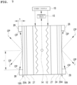
- Fig.7 is an illustration diagram for illustrating configurations of the nanostructure 16A and the heater 12 of the experimental apparatus 50 shown in Fig. 6 .
- the nanostructure 16A is disposed on each of both surfaces of the heater 12.
- the shielding plate 27 is provided between the heater 12 and each nanostructure 16A.
- the shielding plate 27 uses a SiO 2 plate having a thickness of 0.3 mm.
- the nanostructure 16A is integrated with the heater 12 using the holder 28 with the base 24 facing a heater 12 side and in contact with the shielding plate 27.
- the base 24 is made of Ni and uses a Ni substrate having a thickness of 0.1 mm.
- the holder 28 uses Photoveel (registered trademark) manufactured by Ferrotec Ceramics Corporation.
- the holder 28 has a circular opening that allows the surface of the multilayer film 25A constituting the nanostructure 16A to expose.
- a thickness t of the holder 28 is 1.5 mm, and a radius r of the opening is 10 mm.
- the nanostructure 16A was introduced into the container 11, and the inside of the container 11 was subjected to vacuum evacuation.
- the nanostructure 16A was baked with the heater 12 to remove water and the like adhering to the surface of the nanostructure 16A.
- the hydrogen-based gas was introduced into the container 11, and hydrogen was occluded into the nanostructure 16A.
- Conditions for introducing the hydrogen-based gas were 80°C to 500°C and 100 Pa or more.
- the inside of the container 11 was subjected to vacuum evacuation, the temperature of the heater 12 was increased, and the temperature of the surface of the nanostructure 16A was set to 600°C.
- Experiments 1 to 4 were conducted by changing purity of the hydrogen-based gas or the configuration of the nanostructure 16A.
- the nanostructure 16A used in Experiment 1 included the multilayer film 25A formed on the surface of the base 24 and obtained by stacking six of the first layer 31 made of Cu and having a thickness of 2 nm and six of the second layer 32 made of Ni and having a thickness of 14 nm.
- the purity of the hydrogen-based gas used in Experiment 1 was 7 N (99.99999% or more).
- Experiment 2 was conducted under the same conditions as those in Experiment 1.
- Experiment 3 was conducted under the same conditions as those in Experiment 1 and Experiment 2, except that the purity of the hydrogen-based gas was 5 N (99.999% or more).
- Experiment 4 was conducted under the same conditions as those in Experiment 1 and Experiment 2, except that the thickness of the first layer 31 made of Cu was 3 nm, and the thickness of the second layer 32 made of Ni was 13 nm.
- the charged particles CP emitted from the nanostructure 16A and adhered to the holder 28 were analyzed by an inductively coupled plasma mass spectrometry (ICP-MS) method.
- ICP-MS inductively coupled plasma mass spectrometry
- the charged particles CP adhering to (captured by) the holder 28 were eluted by using 20 mL of nitric acid aqueous solution obtained by diluting TAMAPURE Nitric Acid AA-10 manufactured by Tama Chemical Industries Co., Ltd. five times with pure water, and a concentration of metals in the eluate was measured.
- a concentration of metals in the eluate was measured.
- Table 1 summarizes measurement results of Experiment 1.
- Cu A) Cu (B) Ni (A) Ni (B) Concentration (ppb) 3.88E + 02 1.21E + 02 7.94E + 01 5.96E + 01 Concentration (mg/L) 3.88E - 01 1.21E - 01 7.94E - 02 5.96E - 02 Amount of 2.00E + 01 2.00E + 2.00E + 2.00E + solution (mL) 01 01 01 01 01 Detected element (mg) 7.76E - 03 2.42E - 03 1.59E - 03 1.19E - 03 Atomic weight (g) 6.35E + 01 6.35E + 01 5.87E + 01 5.87E + 01 Number of moles of detected element 7.36E + 16 2.29E + 16 1.63E + 16 1.22E + 16 Solid angle ⁇ 1.50E - 01 1.50E - 01 1.50E - 01 1.50E - 01 Adhesion rate ⁇ 1.00E - 01 1.00E - 01 1.00E - 01 1
- an evaluation (current evaluation) of an average electrical output based on the current and an evaluation (energy evaluation) of an average electrical output based on a total amount of electric power were conducted.
- Table 2 summarizes conditions and results of a current evaluation and an energy evaluation in Experiment 1. Average energy was assumed to be 5 MeV, and conversion efficiency to electric power was set to 10%.
- the current was calculated as 1.6 ⁇ 10 - 19 ⁇ number of moles of emission element ⁇ average ion valence/total emission time.
- the average electrical output in the current evaluation was calculated as assumed energy ⁇ electric power conversion efficiency ⁇ current.
- a total amount of electric power (J) was calculated as elementary charge (1.6 ⁇ 10 - 19) ⁇ number of moles of emission element ⁇ average ion valence x assumed energy.
- An average electrical output (W) in the energy evaluation was calculated as total amount of electric power ⁇ electric power conversion efficiency/total emission time.
- Table 4 summarizes conditions and results of a current evaluation and an energy evaluation in Experiment 2.
- the first electrode 17 is provided on the base 24 of the nanostructure 16A, but is not limited thereto.
- the first electrode 17 may be provided on the multilayer film 25A.
- a silicon substrate doped with impurities to be conductive may be used as the first electrode 17.
- the base 24 may be made of a conductive material, so that the base 24 may be used as the first electrode.
- Heat (excess heat) generated by the nanostructure 16A can be used for various purposes.
- heat of the nanostructure 16A can be converted into electric power by the thermoelectric conversion unit.
- Electric power obtained by conversion by the thermoelectric conversion unit may be supplied to the heater 12.
- the potential difference generation device 10 can save electric power by supplying electric power obtained by conversion by the thermoelectric conversion unit to the heater 12. Even if the power supply 13 is turned on only when the potential difference generation device 10 is started, and the power supply 13 is turned off after the charged particles CP are emitted from the nanostructure 16A, it is possible to continue to operate the potential difference generation device 10 by using electric power obtained by conversion by the thermoelectric conversion unit.
- the excess heat generated by the nanostructure 16A can be recovered using a heat medium.
- the heat medium is heated by the nanostructure 16A and becomes high temperature.
- the high-temperature heat medium is used, for example, in home heating, home water heaters, automobile heaters, agricultural heating machines, road heaters, heat sources for seawater desalination, and auxiliary heat sources for geothermal power generation.
- the heat medium may be a gas or liquid, and is preferably one that has excellent thermal conductivity and is chemically stable. Examples of the gas include a helium gas, an argon gas, a hydrogen gas, a nitrogen gas, water vapor, air, and carbon dioxide.
- liquid examples include water, a molten salt (KNO 3 (40%) to NaNO 3 (60%) or the like), and a liquid metal (for example, Pb).
- a multiphase heat medium in which solid particles are dispersed in a gas or liquid may be used as the heat medium.
- the solid particles are metals, metal compounds, alloys, ceramics, or the like.
- the metals include copper, nickel, titanium, and cobalt.
- the metal compounds include oxides, nitrides, and silicides of the above metals.
- alloys examples include stainless steel and chrome molybdenum steel.
- ceramics examples include alumina.
- Examples of applications of the excess heat generated by the nanostructure 16A include a heat exchanger and a power unit.
- the heat exchanger include a device that performs heat exchange between a heat medium and a gas, a device that performs heat exchange between a heat medium and a liquid, and a device that performs heat exchange between a heat medium and a solid.
- the device that performs heat exchange between a heat medium and a gas is used for air conditioning, preheating air to be supplied to a combustion device, generating hot air for drying or heating, and the like.
- Examples of the combustion device include a boiler, a rotary kiln, a metal heat treatment furnace, a metal processing heating furnace, a hot air stove, a ceramic firing furnace, an oil refining tower, a dry distillation furnace, and a drying furnace.
- the device that performs heat exchange between a heat medium and a liquid is used as a heat source for a boiler, used for oil heating, used as a chemical reaction tank, and the like.
- the device that performs heat exchange between a heat medium and a solid is used as a double pipe rotary heating machine, used for heating particulate substances in a double pipe, and the like.
- Examples of the power unit include a gas turbine, a steam turbine, a stirling engine, and an organic rankine cycle system (ORCS).
Landscapes
- Chemical & Material Sciences (AREA)
- Chemical Kinetics & Catalysis (AREA)
- Engineering & Computer Science (AREA)
- Organic Chemistry (AREA)
- Life Sciences & Earth Sciences (AREA)
- Electrochemistry (AREA)
- General Chemical & Material Sciences (AREA)
- Sustainable Development (AREA)
- Manufacturing & Machinery (AREA)
- Sustainable Energy (AREA)
- Combustion & Propulsion (AREA)
- Inorganic Chemistry (AREA)
- General Life Sciences & Earth Sciences (AREA)
- Environmental & Geological Engineering (AREA)
- Composite Materials (AREA)
- Geology (AREA)
- Hydrogen, Water And Hydrids (AREA)
- Fuel Cell (AREA)
- Battery Electrode And Active Subsutance (AREA)
- Physics & Mathematics (AREA)
- Thermal Sciences (AREA)
- Mechanical Engineering (AREA)
- General Engineering & Computer Science (AREA)
- Investigating Or Analyzing Materials By The Use Of Fluid Adsorption Or Reactions (AREA)
Applications Claiming Priority (2)
| Application Number | Priority Date | Filing Date | Title |
|---|---|---|---|
| JP2022084169A JP7398144B2 (ja) | 2022-05-23 | 2022-05-23 | 電位差発生デバイス |
| PCT/JP2023/015547 WO2023228630A1 (ja) | 2022-05-23 | 2023-04-19 | 電位差発生デバイス |
Publications (1)
| Publication Number | Publication Date |
|---|---|
| EP4530556A1 true EP4530556A1 (de) | 2025-04-02 |
Family
ID=88919163
Family Applications (1)
| Application Number | Title | Priority Date | Filing Date |
|---|---|---|---|
| EP23811508.3A Pending EP4530556A1 (de) | 2022-05-23 | 2023-04-19 | Vorrichtung zur erzeugung von potentialdifferenzen |
Country Status (9)
| Country | Link |
|---|---|
| US (1) | US20250323286A1 (de) |
| EP (1) | EP4530556A1 (de) |
| JP (1) | JP7398144B2 (de) |
| KR (1) | KR20240156385A (de) |
| CN (1) | CN119096099A (de) |
| AU (1) | AU2023277884A1 (de) |
| CA (1) | CA3252234A1 (de) |
| TW (1) | TW202408146A (de) |
| WO (1) | WO2023228630A1 (de) |
Family Cites Families (7)
| Publication number | Priority date | Publication date | Assignee | Title |
|---|---|---|---|---|
| WO2000077266A1 (fr) * | 1999-06-11 | 2000-12-21 | Sumitomo Electric Industries, Ltd. | Materiau en couches bloquant l'hydrogene |
| JP4646162B2 (ja) * | 2000-09-19 | 2011-03-09 | 株式会社日本製鋼所 | 水素吸蔵合金発電装置および水素吸蔵合金を用いた発電方法 |
| JP2003336798A (ja) * | 2002-05-17 | 2003-11-28 | Toyota Motor Corp | 水素吸蔵装置及び水素吸蔵方法 |
| JP4821962B2 (ja) * | 2005-06-30 | 2011-11-24 | トヨタ自動車株式会社 | 燃料電池システム |
| JP2009252370A (ja) * | 2008-04-01 | 2009-10-29 | Toyota Motor Corp | 燃料電池、燃料電池システムおよび燃料電池の再生方法 |
| CN111094867B (zh) * | 2017-06-15 | 2022-01-25 | 绿净星球股份有限公司 | 发热装置及发热方法 |
| JP7488548B2 (ja) * | 2020-03-31 | 2024-05-22 | 株式会社クリーンプラネット | 発熱装置 |
-
2022
- 2022-05-23 JP JP2022084169A patent/JP7398144B2/ja active Active
-
2023
- 2023-04-19 CA CA3252234A patent/CA3252234A1/en active Pending
- 2023-04-19 CN CN202380030710.6A patent/CN119096099A/zh active Pending
- 2023-04-19 KR KR1020247031323A patent/KR20240156385A/ko active Pending
- 2023-04-19 US US18/866,333 patent/US20250323286A1/en active Pending
- 2023-04-19 WO PCT/JP2023/015547 patent/WO2023228630A1/ja not_active Ceased
- 2023-04-19 AU AU2023277884A patent/AU2023277884A1/en active Pending
- 2023-04-19 EP EP23811508.3A patent/EP4530556A1/de active Pending
- 2023-05-23 TW TW112119092A patent/TW202408146A/zh unknown
Also Published As
| Publication number | Publication date |
|---|---|
| TW202408146A (zh) | 2024-02-16 |
| KR20240156385A (ko) | 2024-10-29 |
| WO2023228630A1 (ja) | 2023-11-30 |
| AU2023277884A1 (en) | 2024-12-05 |
| US20250323286A1 (en) | 2025-10-16 |
| JP7398144B2 (ja) | 2023-12-14 |
| CN119096099A (zh) | 2024-12-06 |
| JP2023172398A (ja) | 2023-12-06 |
| CA3252234A1 (en) | 2025-07-09 |
Similar Documents
| Publication | Publication Date | Title |
|---|---|---|
| AU2021254632B2 (en) | Heat generating device and method for generating heat | |
| RU2509828C2 (ru) | Система и способ производства химической потенциальной энергии | |
| US20030159922A1 (en) | Electrical cells, components and methods | |
| CN102639744A (zh) | 用于电化学应用的高导电性表面以及制备所述高导电性表面的方法 | |
| JP7488548B2 (ja) | 発熱装置 | |
| CN104159669A (zh) | 光水分解反应用电极以及其制造方法 | |
| US9790602B2 (en) | Techniques for photocatalytic hydrogen generation | |
| US5134042A (en) | Solid compositions for fuel cells, sensors and catalysts | |
| Liu et al. | Active Cu and Fe nanoparticles codecorated ruddlesden–popper‐type perovskite as solid oxide electrolysis cells cathode for CO2 splitting | |
| WO1997026684A9 (en) | Single-crystal oxygen ion conductor | |
| Ding et al. | Joule Heating for Metal Oxide Electrocatalyst Fabrication: A Fast‐Track Strategy for Water Electrolysis | |
| EP4530556A1 (de) | Vorrichtung zur erzeugung von potentialdifferenzen | |
| US12247766B2 (en) | Heat generating method | |
| JP5455607B2 (ja) | 固体酸化物燃料電池及びその運転方法 | |
| Zhang et al. | Intermediate temperature solid oxide cell with a barrier layer free oxygen electrode and phase inversion derived hydrogen electrode | |
| HK40113791A (zh) | 电位差产生装置 | |
| Rij et al. | A novel Ni-CERMET electrode based on a proton conducting electrolyte | |
| WO2015130820A1 (en) | An electrolysis reactor system | |
| JP7031564B2 (ja) | 燃料電池用セパレータの製造方法 | |
| CN118661299A (zh) | 发电元件、发电装置和发电方法 | |
| JP2004103549A (ja) | 固体電解質用電極、その製造方法、その使用方法並びに固体電解質型酸素センサー及び排ガスセンサー | |
| Hertz | Microfabrication methods to improve the kinetics of the yttria stabilized zirconia--platinum--oxygen electrode | |
| TW201239098A (en) | Clean steel production process using carbon-free renewable energy source | |
| JP2005298307A (ja) | 燃料電池用の燃料改質器及び燃料改質方法 | |
| JP5393538B2 (ja) | 固体電解質型酸素センサー及び排ガスセンサー |
Legal Events
| Date | Code | Title | Description |
|---|---|---|---|
| STAA | Information on the status of an ep patent application or granted ep patent |
Free format text: STATUS: THE INTERNATIONAL PUBLICATION HAS BEEN MADE |
|
| PUAI | Public reference made under article 153(3) epc to a published international application that has entered the european phase |
Free format text: ORIGINAL CODE: 0009012 |
|
| STAA | Information on the status of an ep patent application or granted ep patent |
Free format text: STATUS: REQUEST FOR EXAMINATION WAS MADE |
|
| 17P | Request for examination filed |
Effective date: 20241223 |
|
| AK | Designated contracting states |
Kind code of ref document: A1 Designated state(s): AL AT BE BG CH CY CZ DE DK EE ES FI FR GB GR HR HU IE IS IT LI LT LU LV MC ME MK MT NL NO PL PT RO RS SE SI SK SM TR |
|
| DAV | Request for validation of the european patent (deleted) | ||
| DAX | Request for extension of the european patent (deleted) |