EP4530508A1 - Proportionalventil zur regelung des durchflusses eines fluids - Google Patents
Proportionalventil zur regelung des durchflusses eines fluids Download PDFInfo
- Publication number
- EP4530508A1 EP4530508A1 EP23382982.9A EP23382982A EP4530508A1 EP 4530508 A1 EP4530508 A1 EP 4530508A1 EP 23382982 A EP23382982 A EP 23382982A EP 4530508 A1 EP4530508 A1 EP 4530508A1
- Authority
- EP
- European Patent Office
- Prior art keywords
- connector
- valve
- connectors
- fluid
- conduits
- Prior art date
- Legal status (The legal status is an assumption and is not a legal conclusion. Google has not performed a legal analysis and makes no representation as to the accuracy of the status listed.)
- Granted
Links
Images



Classifications
-
- F—MECHANICAL ENGINEERING; LIGHTING; HEATING; WEAPONS; BLASTING
- F16—ENGINEERING ELEMENTS AND UNITS; GENERAL MEASURES FOR PRODUCING AND MAINTAINING EFFECTIVE FUNCTIONING OF MACHINES OR INSTALLATIONS; THERMAL INSULATION IN GENERAL
- F16K—VALVES; TAPS; COCKS; ACTUATING-FLOATS; DEVICES FOR VENTING OR AERATING
- F16K11/00—Multiple-way valves, e.g. mixing valves; Pipe fittings incorporating such valves
- F16K11/10—Multiple-way valves, e.g. mixing valves; Pipe fittings incorporating such valves with two or more closure members not moving as a unit
- F16K11/14—Multiple-way valves, e.g. mixing valves; Pipe fittings incorporating such valves with two or more closure members not moving as a unit operated by one actuating member, e.g. a handle
- F16K11/16—Multiple-way valves, e.g. mixing valves; Pipe fittings incorporating such valves with two or more closure members not moving as a unit operated by one actuating member, e.g. a handle which only slides, or only turns, or only swings in one plane
- F16K11/168—Multiple-way valves, e.g. mixing valves; Pipe fittings incorporating such valves with two or more closure members not moving as a unit operated by one actuating member, e.g. a handle which only slides, or only turns, or only swings in one plane only swings
-
- F—MECHANICAL ENGINEERING; LIGHTING; HEATING; WEAPONS; BLASTING
- F15—FLUID-PRESSURE ACTUATORS; HYDRAULICS OR PNEUMATICS IN GENERAL
- F15B—SYSTEMS ACTING BY MEANS OF FLUIDS IN GENERAL; FLUID-PRESSURE ACTUATORS, e.g. SERVOMOTORS; DETAILS OF FLUID-PRESSURE SYSTEMS, NOT OTHERWISE PROVIDED FOR
- F15B11/00—Servomotor systems without provision for follow-up action; Circuits therefor
- F15B11/006—Hydraulic "Wheatstone bridge" circuits, i.e. with four nodes, P-A-T-B, and on-off or proportional valves in each link
-
- F—MECHANICAL ENGINEERING; LIGHTING; HEATING; WEAPONS; BLASTING
- F15—FLUID-PRESSURE ACTUATORS; HYDRAULICS OR PNEUMATICS IN GENERAL
- F15B—SYSTEMS ACTING BY MEANS OF FLUIDS IN GENERAL; FLUID-PRESSURE ACTUATORS, e.g. SERVOMOTORS; DETAILS OF FLUID-PRESSURE SYSTEMS, NOT OTHERWISE PROVIDED FOR
- F15B13/00—Details of servomotor systems ; Valves for servomotor systems
- F15B13/02—Fluid distribution or supply devices characterised by their adaptation to the control of servomotors
- F15B13/04—Fluid distribution or supply devices characterised by their adaptation to the control of servomotors for use with a single servomotor
- F15B13/0401—Valve members; Fluid interconnections therefor
-
- F—MECHANICAL ENGINEERING; LIGHTING; HEATING; WEAPONS; BLASTING
- F15—FLUID-PRESSURE ACTUATORS; HYDRAULICS OR PNEUMATICS IN GENERAL
- F15B—SYSTEMS ACTING BY MEANS OF FLUIDS IN GENERAL; FLUID-PRESSURE ACTUATORS, e.g. SERVOMOTORS; DETAILS OF FLUID-PRESSURE SYSTEMS, NOT OTHERWISE PROVIDED FOR
- F15B13/00—Details of servomotor systems ; Valves for servomotor systems
- F15B13/02—Fluid distribution or supply devices characterised by their adaptation to the control of servomotors
- F15B13/04—Fluid distribution or supply devices characterised by their adaptation to the control of servomotors for use with a single servomotor
- F15B13/044—Fluid distribution or supply devices characterised by their adaptation to the control of servomotors for use with a single servomotor operated by electrically-controlled means, e.g. solenoids, torque-motors
- F15B13/0444—Fluid distribution or supply devices characterised by their adaptation to the control of servomotors for use with a single servomotor operated by electrically-controlled means, e.g. solenoids, torque-motors with rotary electric motor
-
- F—MECHANICAL ENGINEERING; LIGHTING; HEATING; WEAPONS; BLASTING
- F16—ENGINEERING ELEMENTS AND UNITS; GENERAL MEASURES FOR PRODUCING AND MAINTAINING EFFECTIVE FUNCTIONING OF MACHINES OR INSTALLATIONS; THERMAL INSULATION IN GENERAL
- F16K—VALVES; TAPS; COCKS; ACTUATING-FLOATS; DEVICES FOR VENTING OR AERATING
- F16K7/00—Diaphragm valves or cut-off apparatus, e.g. with a member deformed, but not moved bodily, to close the passage ; Pinch valves
- F16K7/02—Diaphragm valves or cut-off apparatus, e.g. with a member deformed, but not moved bodily, to close the passage ; Pinch valves with tubular diaphragm
- F16K7/04—Diaphragm valves or cut-off apparatus, e.g. with a member deformed, but not moved bodily, to close the passage ; Pinch valves with tubular diaphragm constrictable by external radial force
- F16K7/06—Diaphragm valves or cut-off apparatus, e.g. with a member deformed, but not moved bodily, to close the passage ; Pinch valves with tubular diaphragm constrictable by external radial force by means of a screw-spindle, cam, or other mechanical means
- F16K7/068—Diaphragm valves or cut-off apparatus, e.g. with a member deformed, but not moved bodily, to close the passage ; Pinch valves with tubular diaphragm constrictable by external radial force by means of a screw-spindle, cam, or other mechanical means by bending the hose
-
- F—MECHANICAL ENGINEERING; LIGHTING; HEATING; WEAPONS; BLASTING
- F15—FLUID-PRESSURE ACTUATORS; HYDRAULICS OR PNEUMATICS IN GENERAL
- F15B—SYSTEMS ACTING BY MEANS OF FLUIDS IN GENERAL; FLUID-PRESSURE ACTUATORS, e.g. SERVOMOTORS; DETAILS OF FLUID-PRESSURE SYSTEMS, NOT OTHERWISE PROVIDED FOR
- F15B2211/00—Circuits for servomotor systems
- F15B2211/30—Directional control
- F15B2211/305—Directional control characterised by the type of valves
- F15B2211/3056—Assemblies of multiple valves
- F15B2211/30565—Assemblies of multiple valves having multiple valves for a single output member, e.g. for creating higher valve function by use of multiple valves like two 2/2-valves replacing a 5/3-valve
- F15B2211/30575—Assemblies of multiple valves having multiple valves for a single output member, e.g. for creating higher valve function by use of multiple valves like two 2/2-valves replacing a 5/3-valve in a Wheatstone Bridge arrangement (also half bridges)
Definitions
- the present invention relates to the technical sector of valves intended to regulate or control fluid circulation. More specifically, the invention relates to a 4-way, 3-position, proportional, directional valve assembly with complementary accessories that are required for its assembly and for fluid distribution.
- Directional control valves are those responsible for changing the direction of flow of a fluid (whether gas or liquid) that can be conducted towards actuation cylinders, pneumatic clamps and, in general, for any circuit in which it is required to introduce/extract said fluid in successive operating cycles to transform hydraulic/pneumatic energy into linear movements, more specifically, double-acting tools and cylinders.
- 4-way valves have 4 ports, which can be named by the function that each port implements or by the system component connected thereto: pressure port (to which the fluid supply source is connected, with a set pressure), advance port (port that causes the movement of the mechanism controlled by the valve in one direction), retraction or recoil port (which causes the movement of said mechanism in the opposite direction to that of advance) and tank port (from which the fluid already “used” in the actuation of the controlled mechanism comes out, for recycling or storage thereof).
- pressure port to which the fluid supply source is connected, with a set pressure
- advance port port that causes the movement of the mechanism controlled by the valve in one direction
- retraction or recoil port which causes the movement of said mechanism in the opposite direction to that of advance
- tank port from which the fluid already “used” in the actuation of the controlled mechanism comes out, for recycling or storage thereof).
- valves are known in which fluid flow control is obtained by deformation of a conduit through which said fluid circulates, such that this deformation causes a closure or opening of the passage section of the corresponding conduit.
- the deformation of said tube is produced by the action of an ad-hoc mechanism, i.e., specifically intended or suited to achieve that deformation.
- the present invention provides a proportional directional valve for regulating fluid flow.
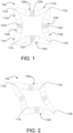
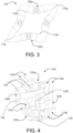
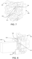
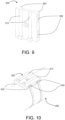
- the valve comprises several conduits, these conduits being characterised in that they can be folded, forming a constriction that limits or completely cuts off fluid flow, and can be unfolded or extended, at least partially, to allow fluid to flow therethrough.
- These folding and unfolding actions of the conduits are carried out in a controlled manner to obtain an adequate flow rate, which depends proportionally on how much the conduits are folded or unfolded. Therefore, the valve is proportional.
- the valve further comprises various connectors that connect the conduits to each other, each connector interconnecting two independent conduits, forming a circuit through which the fluid or different fluids move.
- These connectors are designed to enable the input of pressurised fluid and the output of pressurised fluid, wherein the output fluid may be the same one that entered or a different one.
Landscapes
- Engineering & Computer Science (AREA)
- General Engineering & Computer Science (AREA)
- Mechanical Engineering (AREA)
- Physics & Mathematics (AREA)
- Fluid Mechanics (AREA)
- Fluid-Pressure Circuits (AREA)
Priority Applications (2)
| Application Number | Priority Date | Filing Date | Title |
|---|---|---|---|
| EP23382982.9A EP4530508B1 (de) | 2023-09-27 | 2023-09-27 | Proportionalventil zur regelung des durchflusses eines fluids |
| ES23382982T ES3065298T3 (de) | 2023-09-27 | 2023-09-27 |
Applications Claiming Priority (1)
| Application Number | Priority Date | Filing Date | Title |
|---|---|---|---|
| EP23382982.9A EP4530508B1 (de) | 2023-09-27 | 2023-09-27 | Proportionalventil zur regelung des durchflusses eines fluids |
Publications (3)
| Publication Number | Publication Date |
|---|---|
| EP4530508A1 true EP4530508A1 (de) | 2025-04-02 |
| EP4530508C0 EP4530508C0 (de) | 2026-02-25 |
| EP4530508B1 EP4530508B1 (de) | 2026-02-25 |
Family
ID=88833824
Family Applications (1)
| Application Number | Title | Priority Date | Filing Date |
|---|---|---|---|
| EP23382982.9A Active EP4530508B1 (de) | 2023-09-27 | 2023-09-27 | Proportionalventil zur regelung des durchflusses eines fluids |
Country Status (2)
| Country | Link |
|---|---|
| EP (1) | EP4530508B1 (de) |
| ES (1) | ES3065298T3 (de) |
Citations (4)
| Publication number | Priority date | Publication date | Assignee | Title |
|---|---|---|---|---|
| JPS5891066U (ja) * | 1981-12-16 | 1983-06-20 | 株式会社中央製作所 | チユ−ブ式折曲げ弁 |
| US5707038A (en) * | 1996-10-23 | 1998-01-13 | Cocatre-Zilgien; Jan H. | Hinged kink valve |
| US20050053501A1 (en) * | 2003-05-13 | 2005-03-10 | Yutaka Akahori | Tube valve, a tube valve apparatus and a head cleaning apparatus |
| JP2011131152A (ja) * | 2009-12-24 | 2011-07-07 | Kao Corp | 液体滴下装置及び液体滴下装置における液垂れ防止方法 |
-
2023
- 2023-09-27 ES ES23382982T patent/ES3065298T3/es active Active
- 2023-09-27 EP EP23382982.9A patent/EP4530508B1/de active Active
Patent Citations (4)
| Publication number | Priority date | Publication date | Assignee | Title |
|---|---|---|---|---|
| JPS5891066U (ja) * | 1981-12-16 | 1983-06-20 | 株式会社中央製作所 | チユ−ブ式折曲げ弁 |
| US5707038A (en) * | 1996-10-23 | 1998-01-13 | Cocatre-Zilgien; Jan H. | Hinged kink valve |
| US20050053501A1 (en) * | 2003-05-13 | 2005-03-10 | Yutaka Akahori | Tube valve, a tube valve apparatus and a head cleaning apparatus |
| JP2011131152A (ja) * | 2009-12-24 | 2011-07-07 | Kao Corp | 液体滴下装置及び液体滴下装置における液垂れ防止方法 |
Also Published As
| Publication number | Publication date |
|---|---|
| ES3065298T3 (de) | 2026-05-05 |
| EP4530508C0 (de) | 2026-02-25 |
| EP4530508B1 (de) | 2026-02-25 |
Similar Documents
| Publication | Publication Date | Title |
|---|---|---|
| US7721973B2 (en) | Valve | |
| US7243591B2 (en) | Hydraulic valve arrangement | |
| US8540207B2 (en) | Fluid flow control assembly | |
| US8690072B2 (en) | Radiator bypass valve | |
| EP0232014A2 (de) | Servoregler mit Energieerhaltung | |
| JPS5850370A (ja) | 同軸二方向スプ−ル弁 | |
| JPS5852082B2 (ja) | エキリヨクシキセイギヨソウチ | |
| EP4530508B1 (de) | Proportionalventil zur regelung des durchflusses eines fluids | |
| CN104132016A (zh) | 三通流量阀、负载敏感多路阀、液压系统和工程机械 | |
| JPS60501171A (ja) | 制御弁およびそれを用いた液圧装置 | |
| JPS59500730A (ja) | 制御装置 | |
| US4827981A (en) | Fail-fixed servovalve with controlled hard-over leakage | |
| EP4567310A1 (de) | Dreiwegeventil, insbesondere mit modulierender funktion | |
| GB2106188A (en) | Hydraulic cylinder control | |
| US3443586A (en) | Four-way change-over device for hydraulic installations | |
| US5255705A (en) | Hydraulic pressure control system | |
| CN114576224A (zh) | 一种控制阀、换向阀及其控制系统 | |
| US10955057B2 (en) | Hydraulic control valve unit | |
| KR930000302B1 (ko) | 밸브장치 | |
| CN121206008A (zh) | 具有流动调节结构的液压阀 | |
| JP2765605B2 (ja) | 油圧作業機の油圧回路 | |
| JPH0514001Y2 (de) | ||
| JP3023182U (ja) | 弁及び該弁を備えるパイロット操作弁 | |
| JPH0612802U (ja) | 速度制御弁 | |
| Low et al. | A Novel 3D Ring-Based Flapper Valve for Soft Robotic Applications. Robotics 2022, 11, 2 |
Legal Events
| Date | Code | Title | Description |
|---|---|---|---|
| PUAI | Public reference made under article 153(3) epc to a published international application that has entered the european phase |
Free format text: ORIGINAL CODE: 0009012 |
|
| STAA | Information on the status of an ep patent application or granted ep patent |
Free format text: STATUS: REQUEST FOR EXAMINATION WAS MADE |
|
| 17P | Request for examination filed |
Effective date: 20241118 |
|
| AK | Designated contracting states |
Kind code of ref document: A1 Designated state(s): AL AT BE BG CH CY CZ DE DK EE ES FI FR GB GR HR HU IE IS IT LI LT LU LV MC ME MK MT NL NO PL PT RO RS SE SI SK SM TR |
|
| REG | Reference to a national code |
Ref legal event code: R079 Free format text: PREVIOUS MAIN CLASS: F16K0007080000 Ipc: F16K0007060000 Ref country code: DE Ref legal event code: R079 Ref document number: 602023012597 Country of ref document: DE Free format text: PREVIOUS MAIN CLASS: F16K0007080000 Ipc: F16K0007060000 |
|
| GRAP | Despatch of communication of intention to grant a patent |
Free format text: ORIGINAL CODE: EPIDOSNIGR1 |
|
| STAA | Information on the status of an ep patent application or granted ep patent |
Free format text: STATUS: GRANT OF PATENT IS INTENDED |
|
| RIC1 | Information provided on ipc code assigned before grant |
Ipc: F16K 7/06 20060101AFI20251105BHEP |
|
| INTG | Intention to grant announced |
Effective date: 20251119 |
|
| GRAS | Grant fee paid |
Free format text: ORIGINAL CODE: EPIDOSNIGR3 |
|
| GRAA | (expected) grant |
Free format text: ORIGINAL CODE: 0009210 |
|
| STAA | Information on the status of an ep patent application or granted ep patent |
Free format text: STATUS: THE PATENT HAS BEEN GRANTED |
|
| AK | Designated contracting states |
Kind code of ref document: B1 Designated state(s): AL AT BE BG CH CY CZ DE DK EE ES FI FR GB GR HR HU IE IS IT LI LT LU LV MC ME MK MT NL NO PL PT RO RS SE SI SK SM TR |
|
| REG | Reference to a national code |
Ref country code: CH Ref legal event code: F10 Free format text: ST27 STATUS EVENT CODE: U-0-0-F10-F00 (AS PROVIDED BY THE NATIONAL OFFICE) Effective date: 20260225 Ref country code: GB Ref legal event code: FG4D |
|
| REG | Reference to a national code |
Ref country code: DE Ref legal event code: R096 Ref document number: 602023012597 Country of ref document: DE |
|
| REG | Reference to a national code |
Ref country code: IE Ref legal event code: FG4D |
|
| U01 | Request for unitary effect filed |
Effective date: 20260313 |
|
| U07 | Unitary effect registered |
Designated state(s): AT BE BG DE DK EE FI FR IT LT LU LV MT NL PT RO SE SI Effective date: 20260319 |
|
| REG | Reference to a national code |
Ref country code: ES Ref legal event code: FG2A Ref document number: 3065298 Country of ref document: ES Kind code of ref document: T3 Effective date: 20260505 |