EP4530487A2 - Procédé de fixation amovible d'une plaque de recouvrement sur une unité encastrée - Google Patents
Procédé de fixation amovible d'une plaque de recouvrement sur une unité encastrée Download PDFInfo
- Publication number
- EP4530487A2 EP4530487A2 EP25157221.0A EP25157221A EP4530487A2 EP 4530487 A2 EP4530487 A2 EP 4530487A2 EP 25157221 A EP25157221 A EP 25157221A EP 4530487 A2 EP4530487 A2 EP 4530487A2
- Authority
- EP
- European Patent Office
- Prior art keywords
- bushing
- threaded
- threaded rod
- longitudinal direction
- relative
- Prior art date
- Legal status (The legal status is an assumption and is not a legal conclusion. Google has not performed a legal analysis and makes no representation as to the accuracy of the status listed.)
- Pending
Links
Images


Classifications
-
- F—MECHANICAL ENGINEERING; LIGHTING; HEATING; WEAPONS; BLASTING
- F16—ENGINEERING ELEMENTS AND UNITS; GENERAL MEASURES FOR PRODUCING AND MAINTAINING EFFECTIVE FUNCTIONING OF MACHINES OR INSTALLATIONS; THERMAL INSULATION IN GENERAL
- F16B—DEVICES FOR FASTENING OR SECURING CONSTRUCTIONAL ELEMENTS OR MACHINE PARTS TOGETHER, e.g. NAILS, BOLTS, CIRCLIPS, CLAMPS, CLIPS OR WEDGES; JOINTS OR JOINTING
- F16B37/00—Nuts or like thread-engaging members
- F16B37/08—Quickly-detachable or mountable nuts, e.g. consisting of two or more parts; Nuts movable along the bolt after tilting the nut
- F16B37/0807—Nuts engaged from the end of the bolt, e.g. axially slidable nuts
- F16B37/0864—Nuts engaged from the end of the bolt, e.g. axially slidable nuts with the threaded portions of the nut engaging the thread of the bolt by pressing or rotating an external retaining member such as a cap, a nut, a ring or a sleeve
-
- E—FIXED CONSTRUCTIONS
- E03—WATER SUPPLY; SEWERAGE
- E03D—WATER-CLOSETS OR URINALS WITH FLUSHING DEVICES; FLUSHING VALVES THEREFOR
- E03D5/00—Special constructions of flushing devices, e.g. closed flushing system
- E03D5/02—Special constructions of flushing devices, e.g. closed flushing system operated mechanically or hydraulically (or pneumatically) also details such as push buttons, levers and pull-card therefor
- E03D5/028—Pusher plates and actuating mechanisms for built-in cisterns
-
- F—MECHANICAL ENGINEERING; LIGHTING; HEATING; WEAPONS; BLASTING
- F16—ENGINEERING ELEMENTS AND UNITS; GENERAL MEASURES FOR PRODUCING AND MAINTAINING EFFECTIVE FUNCTIONING OF MACHINES OR INSTALLATIONS; THERMAL INSULATION IN GENERAL
- F16B—DEVICES FOR FASTENING OR SECURING CONSTRUCTIONAL ELEMENTS OR MACHINE PARTS TOGETHER, e.g. NAILS, BOLTS, CIRCLIPS, CLAMPS, CLIPS OR WEDGES; JOINTS OR JOINTING
- F16B37/00—Nuts or like thread-engaging members
- F16B37/04—Devices for fastening nuts to surfaces, e.g. sheets, plates
- F16B37/044—Nut cages
-
- F—MECHANICAL ENGINEERING; LIGHTING; HEATING; WEAPONS; BLASTING
- F16—ENGINEERING ELEMENTS AND UNITS; GENERAL MEASURES FOR PRODUCING AND MAINTAINING EFFECTIVE FUNCTIONING OF MACHINES OR INSTALLATIONS; THERMAL INSULATION IN GENERAL
- F16B—DEVICES FOR FASTENING OR SECURING CONSTRUCTIONAL ELEMENTS OR MACHINE PARTS TOGETHER, e.g. NAILS, BOLTS, CIRCLIPS, CLAMPS, CLIPS OR WEDGES; JOINTS OR JOINTING
- F16B37/00—Nuts or like thread-engaging members
- F16B37/08—Quickly-detachable or mountable nuts, e.g. consisting of two or more parts; Nuts movable along the bolt after tilting the nut
- F16B37/0807—Nuts engaged from the end of the bolt, e.g. axially slidable nuts
- F16B37/0821—Nuts engaged from the end of the bolt, e.g. axially slidable nuts in two halves pivotally connected
Definitions
- the invention relates to a mounting device, a system comprising the mounting device and a method for using the system for fixing a cover plate to a concealed unit, in particular to a wall of a cistern.
- the mounting devices are used to fix cover plates, which are used to conceal elements of concealed units of a sanitary installation, for example, elements of a concealed cistern, a concealed thermostat unit, or a concealed pipe connection point, relative to the concealed units.
- the cover plates serve to conceal the elements, but often also to implement additional functions.
- Such cover plates are therefore often designed as actuator plates that have actuation buttons via which the concealed unit can be operated.
- the cover plates are thus usually mounted on a false wall in such a way that they are accessible from a space defined by the false wall, thereby concealing a section of the concealed unit located behind the false wall.
- a pre-wall is to be understood in particular as a wall element which is arranged in front of another wall and is connected to it, forming a hollow space between the pre-wall and the wall.
- a cover plate designed as an actuation plate is usually provided, spaced separately from the cistern.
- the actuation plate is used to activate the functions of the cistern.
- the actuation plate usually has an actuation plate frame which is releasably fixed relative to the cistern, as well as an actuation panel with actuation buttons which are releasably fixed to the actuation plate frame.
- the actuation buttons are usually connected to a drain valve via actuation pins or electronics so that a flush can be triggered via them.
- the actuation plate is conventionally fixed to the cistern using appropriate connecting means.
- a generic cistern has a wall in which flush water is collected for a flush.
- the actuation plate is usually fixed relative to the wall, in particular directly or indirectly fixed to the wall. Preferably, it is attached to a splash guard plate, which is releasably fixed to the wall and closes an inspection opening provided in the wall.
- the section of the actuator plate via which the actuator plate is actuated, in particular the actuator plate, and the wall are usually spaced apart from each other in the operating state and fixed relative to each other by the corresponding connecting means.
- a flush-mounted unit usually has a wall section, for example, a sheet metal or plastic plate or a suitable profile, to which the cover plate is fixed using conventional connecting means.
- the cover plate in particular the described actuating plate of a cistern, covers a maintenance opening in the pre-wall.
- the cover plate can be loosened and removed from the maintenance opening in order to enable, in particular for maintenance personnel, access to the visually concealed elements of the concealed unit, in particular of the cistern, through the maintenance opening.
- the fixation of the cover plate, in particular of the actuating plate, relative to the wall of the cistern is therefore regularly loosened and restored after completion of the maintenance.
- the connecting means are therefore usually designed in such a way that they enable releasable fixation.
- the connecting means are generically designed as a mounting device comprising a threaded rod which extends with its longitudinal axis in a longitudinal direction and has a thread in particular along the predominant part of its longitudinal extent.
- the mounting device generically comprises a thread fixed to the concealed unit, in particular to the wall of the cistern, and formed corresponding to the thread of the threaded rod.
- the longitudinal extension of the threaded rod is understood to be the extension that runs along a longitudinal axis along which the threaded rod forms its thread, so that the thread runs around the longitudinal axis. The direction along this longitudinal axis is referred to as the longitudinal direction.
- the threaded rod is guided through a designated opening in the cover plate and screwed into the thread provided on the cistern, whereby a force is built up that applies the cover plate to the pre-wall and fixes it relative to the concealed unit, in particular to the wall of the cistern.
- at least one further mounting device is provided to support the fixation.
- These multiple mounting devices are usually spaced from one another in a direction perpendicular to the longitudinal direction, with the mounting devices preferably each having a distance from the center of the cover plate, relative to the same direction.
- the length of the threaded rod in generic mounting devices regularly exceeds a required minimum length, which corresponds to the distance between the cover plate and the concealed unit, in particular the actuator plate and the wall of the cistern. Because the distance between one side of the wall, to which the cover plate is to be fixed by the at least one mounting device, can vary depending on the room environment, a length of the threaded rod is usually provided that allows appropriate fixing even with an above-average distance between the actuator plate and the wall. In some cases, the length of the threaded rod exceeds the required minimum length by at least 50%, in particular at least 100%. As a result, during assembly, in order to establish the operating state, a comparatively time-consuming process of screwing the threaded rod into the corresponding thread on the concealed unit, in particular the cistern, is necessary.
- the object of the invention is to provide a mounting device and a method for fixing a cover plate to a flush-mounted unit, which at least partially eliminates at least some of the disadvantages of generic mounting devices.
- the mounting device comprises a threaded rod extending with its longitudinal axis in a longitudinal direction and a threaded bushing.
- the threaded rod is inserted into the threaded bushing fixed to the flush-mounted unit to realize an assembled state of the mounting device in which the threaded rod is received within a longitudinal extent by the threaded bushing and in which the threaded bushing and the threaded rod abut one another with mutually corresponding first holding surfaces to inhibit relative movement along the longitudinal direction and in which the threaded rod is displaceable along the longitudinal direction relative to the threaded bushing upon application of an external displacement force acting between the threaded rod and the threaded bushing in the longitudinal direction.
- At least two sections of the threaded bushing which extend over a same longitudinal section of the threaded bushing within the longitudinal extent, are moved towards each other by means of a movement, in particular rotation, of the threaded rod perpendicular to the longitudinal direction, thereby changing their relative position to each other in order to change the mutually corresponding holding surfaces with which the threaded bushing and the threaded rod abut each other, whereby a holding state of the assembly device is realized in which the threaded bushing and the threaded rod abut each other with mutually corresponding second holding surfaces, which are different from the first holding surfaces, and in which by an engagement of a rod thread running around the longitudinal axis of the threaded rod and a bushing thread of the threaded bushing corresponding to the rod thread, upon application of the external displacement force acting between the threaded rod and the threaded bushing in the longitudinal direction, a displacement of the threaded rod to Threaded bushing is avoided.
- the threaded rod preferably has a longitudinal extension length that is at least twice, in particular at least four times, in particular at least ten times, the longitudinal extension.
- the rod thread is preferably formed over at least 50%, in particular at least 70%, of the longitudinal extension length of the threaded rod.
- the threaded rod of the mounting device is rotated about its longitudinal axis, while the rod thread and the socket thread engage with each other, in particular thereby generating a fixing force which acts between the cover plate and the concealed unit, in particular thereby fixing the cover plate to a pre-wall behind which the concealed unit, in particular the cistern, in particular the wall of the cistern, is located.
- the threaded rod has a head element, wherein in the assembled state the threaded rod is inserted into the threaded bushing, in particular by a rotation-free displacement of the threaded rod and threaded bushing relative to one another, until the head element rests against the cover, wherein the holding state is then realized and the threaded rod is moved by rotation about its longitudinal axis in the longitudinal direction towards the threaded bushing, in that the rod thread and bushing thread engage with one another.
- the rotation takes place by more than 270°, in particular by more than 360°, in particular by a multiple of 360°.
- the rotation of the threaded rod applies a pressing force to the cover plate which increases during the course of the rotation and with which it is pressed against a prefabricated wall.
- the cover plate is designed as an actuating plate which has actuating buttons via which the flush-mounted unit can be actuated, wherein the cover plate is detachably mounted to a pre-wall by means of the mounting device such that it is accessible from a space delimited by the pre-wall, and in doing so conceals a section of the flush-mounted unit which is located behind the pre-wall, wherein the cover plate conceals a maintenance opening provided in the pre-wall. After the cover plate has been detached from the pre-wall, the flush-mounted unit is preferably accessible through the maintenance opening.
- the mounting device is reversibly brought from the mounted state to the held state and back from the held state to the mounted state.
- the cover plate is detachably fixed to the pre-wall by means of the mounting device and then detached from the pre-wall for maintenance purposes by means of the mounting device, thereby exposing the maintenance opening.
- an elastic connection is provided between the sections, which counteracts the movement of the sections relative to one another perpendicular to the longitudinal direction, carried out to realize the holding state starting from the assembled state, wherein the connection is formed in particular by at least one elastic web which runs perpendicular to the longitudinal direction.
- the movement of the sections relative to one another creates a restoring force which, when all forces acting on the sections are removed, causes a return to the assembled state.
- the sections are moved relative to one another starting from the assembled state in such a way that they are tilted relative to one another about a tilt axis which runs substantially perpendicular to the longitudinal direction, whereby an angle between the sections about the tilt axis.
- the sections of the threaded bushing are formed by a first bushing part, wherein the threaded bushing has a second bushing part designed as a fixing part, wherein, while realizing the movement of the sections relative to one another, starting from the assembled state to achieve the holding state, the first bushing part is moved relative to the fixing part over a movement distance within a longitudinal extension range.
- the first bushing part in the held state, rests against at least one stop surface formed by the fixing part, wherein the stop surface limits the mobility of the first bushing part relative to the fixing part and the change in the relative position of the sections of the first bushing part.
- the first bushing part is spaced from the stop surface in the assembled state and, starting from the assembled state, is brought into contact with the stop surface of the fixing part by a, in particular continuous, displacement movement relative to the fixing part.
- the displacement movement comprises a rotational movement about an axis of rotation running along the longitudinal direction, wherein the bushing part and the fixing part are configured to correspond to one another in such a way that, starting from the assembled state, the holding state is achieved by executing the rotational movement through a defined angle of rotation, which is in particular less than 270°, preferably less than 180°.
- the holding state is realized by rotating the threaded rod relative to the fixing part.
- the assembly device is, after realization of the holding state of the holding state into the assembly state by moving the first socket part relative to the fixing part by applying a release force, wherein the release force is applied to the first socket part relative to the fixing part by a rotational movement of the threaded rod.
- the cover is designed as an actuating plate and has an actuating plate frame and an actuating panel, wherein the threaded rod is passed through a passage of the actuating plate frame before the assembly state of the assembly device is realized and is then inserted into the threaded bushing upon realization of the assembly state.
- the actuating frame has at least two passages, wherein a threaded rod assigned to it is passed through each of the passages and is then inserted into a threaded bushing assigned to it.
- Each of the threaded rods and the threaded bushing assigned to it are part of a respective assembly device.
- each threaded rod and the threaded bushing assigned to it each form a respective assembly device.
- a mounting device for releasably fixing a cover plate relative to a concealed unit, in particular to the cistern, in particular the wall of the cistern which mounting device has a threaded rod and a threaded bushing.
- the threaded rod extends with its longitudinal axis in a longitudinal direction.
- the threaded rod is received within a longitudinal extent by the threaded bushing.
- the longitudinal extent is formed within a section of the longitudinal extent of the threaded rod.
- the longitudinal extent can be continuous.
- the longitudinal extent is preferably less than half, in particular less than a quarter of the longitudinal extent of the threaded rod, and is in particular between a tenth and a half of the longitudinal extent of the threaded rod.
- the threaded rod and threaded bushing can be arranged one inside the other in the assembled state and in the held state.
- the threaded rod and threaded bushing can of course also be arranged one inside the other in a further state of the assembly device that does not correspond to any of the aforementioned states, wherein a specific state designates a specific arrangement of the components of the assembly device relative to one another.
- the threaded rod has a rod thread that runs around the longitudinal axis of the threaded rod.
- the longitudinal axis of the threaded rod thus corresponds to the axis of rotation about which the threaded rod can be rotated in order to screw the rod thread into a corresponding thread and/or to release it from a screw connection with the corresponding thread.
- the threaded rod can be designed as a screw.
- the threaded rod can have a head element, in particular a screw head, that projects radially, i.e. perpendicular to the longitudinal direction, beyond the rod thread and is formed in particular at a longitudinal end of the threaded rod.
- the screw head is designed in the usual way, for example with an Allen, Phillips, hexagon, or Torx screw head, so that the threaded rod can be easily rotated using a tool.
- the head element can be provided for contact with the cover plate and have a surface for contact with the cover plate.
- the threaded bushing has a bushing thread.
- the bushing thread and the rod thread are each designed to correspond to one another, at least in sections.
- the rod thread can have at least 50%, in particular at least 70% of the longitudinal extension length of the threaded rod, in particular be designed to be continuously circumferential or to be circumferential in circumferential sections.
- the rod thread can have interruptions in the longitudinal direction along the longitudinal axis or be designed to be continuous in the longitudinal direction.
- the socket thread can be designed to be continuous or to be circumferential in circumferential sections.
- the socket thread can be designed to be interrupted or continuous in the longitudinal direction.
- the socket thread and the rod thread can engage with each other in the assembled state and in the held state, wherein they engage behind each other in particular to different depths in the held state and in the assembled state.
- the socket thread can only be formed by engagement with the corresponding rod thread, in particular in that the threaded socket has a deformable, in particular elastically deformable section, into which the rod thread can be screwed to form the socket thread.
- rod and bushing threads are present in the holding state and, in particular, also in the assembled state, whereby preferably the threaded rod in isolation and, in particular, the threaded bushing in isolation, i.e., as a component property without a mandatory connection to another component, has a corresponding thread.
- the rod thread or bushing thread can only be formed through engagement with the corresponding bushing thread or rod thread.
- the threaded rod and threaded bushing When an external displacement force is applied, the threaded rod and threaded bushing can be displaced relative to each other in the longitudinal direction in a preferably non-destructive and reversible manner in the assembled state.
- the displacement force acts between the threaded rod and the threaded bushing and has a predetermined amount.
- Displacement generally refers to a movement, in particular a translational movement, of two bodies relative to one another that can be carried out decoupled from other movements.
- displacement refers to a movement of two bodies relative to one another that does not have a forced coupling with any other movement. In the held state, such a forced coupling is present and includes, in particular, the forced coupling of a rotation and a translation.
- the threaded bushing and the threaded rod bear against one another with corresponding holding surfaces to inhibit relative movement along the longitudinal direction, in particular within the longitudinal extent.
- the action of a force along the longitudinal direction is inhibited.
- the threaded rod and the threaded bushing are designed to correspond to one another in such a way that a first holding force acts in the assembled state in the opposite direction to the external displacement force acting in the longitudinal direction, wherein, if the external displacement force does not exceed the amount of a first holding force, the displacement of the threaded rod and the threaded bushing along the longitudinal direction relative to one another is avoided, and when the external Displacement force: if the external displacement force exceeds the magnitude of the first holding force, the threaded rod and threaded bushing are displaceable relative to one another along the longitudinal direction, wherein in a held state, a second holding force is provided by an interlocking of a rod thread running around the longitudinal axis of the threaded rod and a bushing thread corresponding to the rod thread, which second holding force is greater than the first holding force, so that when the external displacement force is applied, a displacement of the threaded rod relative to the threaded bushing is avoided and such a displacement is only possible when a displacement
- the application of such a displacement force exceeding the second holding force inevitably leads to damage to the mounting device.
- the first holding force can be less than 50%, in particular less than 30%, in particular less than 20% of the second holding force.
- the displacement force is applied externally, which excludes the possibility that the displacement force is formed solely by forces of the static operative connection of the sections and/or components and/or elements of the mounting device.
- the forces of the static active connection can be shear forces and/or caused by residual stresses.
- the external displacement force can be applied, in particular, by a human's physical force. In particular, the external displacement force can be applied by auxiliary devices.
- the threaded bushing and the threaded rod are in contact with each other with the corresponding holding surfaces.
- the threaded bushing and the threaded rod are in contact with each other with the first correspondingly formed Retaining surfaces abut one another.
- the threaded rod has a first retaining surface of the threaded rod and the threaded bushing has a first retaining surface of the threaded bushing, wherein both first retaining surfaces correspond to one another and abut one another.
- At least one of the first retaining surfaces has at least a section of the bushing thread or the rod thread, wherein this first retaining surface abuts the other first retaining surface, in particular with thread webs of the bushing thread or the rod thread.
- the first retaining surface formed by the threaded rod has a section of the threaded rod and the first retaining surface formed by the threaded bushing has a section of the bushing thread, wherein in the assembled state, the threads abut one another with their thread webs within this section. In the held state, the threaded bushing and the threaded rod abut with second retaining surfaces formed in a corresponding manner.
- the pair of corresponding first retaining surfaces in the assembled state differs from the pair of corresponding second retaining surfaces in the held state in that at least one of the first retaining surfaces differs from one of the second retaining surfaces.
- all first holding surfaces differ from all second holding surfaces, wherein it can be provided that one of the first holding surfaces forms a part of one of the second holding surfaces.
- the holding state can be established by bringing the threaded rod and the threaded bushing from the contact of the first holding surfaces to one another to the contact of the second holding surfaces to one another.
- the threaded bushing has at least two, in particular exactly two, sections that extend over a same longitudinal section of the threaded bushing.
- the longitudinal section is a section of the threaded bushing that in the The assembled state or holding state corresponds to a section of the extension of the threaded bushing in the longitudinal direction.
- the at least two sections can extend completely over the same longitudinal section.
- the bushing thread and/or the second holding surface and/or the first holding surface of the threaded bushing is preferably formed by the sections, wherein at least one of the sections, in particular the sections, forms or form the bushing thread.
- the sections extend parallel to the longitudinal extent of the threaded rod in the assembled state and/or holding state.
- the at least two sections are preferably spaced apart from one another perpendicular to the longitudinal direction in the assembled state and/or holding state, in particular opposite one another, and spaced apart from the longitudinal axis of the threaded rod and in particular eccentrically arranged to the longitudinal axis. In the assembled state and/or holding state, they are preferably distributed circumferentially around the threaded rod.
- the at least two sections preferably form the second holding surface of the threaded bushing and particularly preferably the first holding surface of the threaded bushing.
- the at least two sections are also movable relative to one another along a perpendicular to the longitudinal direction.
- the at least two sections are movable relative to each other.
- the two sections can have a smaller distance from each other perpendicular to the longitudinal axis in the holding state compared to their relative position in the assembled state.
- the movement of the sections between the assembled state and the holding state preferably takes place continuously.
- an engagement volume with which the threaded rod and the threaded bushing engage in the holding state increases compared to the assembled state.
- the portion of the holding surface of one component that rests perpendicular to the longitudinal direction against the corresponding holding surface of the other component (threaded rod or threaded bushing).
- the bushing thread is preferably designed in the form of an internal thread.
- the threaded rod has the rod thread in the form of an external thread.
- the threaded rod can be made of metal.
- the threaded rod and/or the threaded bushing can be made of plastic, in particular of thermoplastic.
- the threaded bushing can be designed in several parts.
- the threaded bushing preferably comprises fewer than ten, particularly preferably fewer than five parts.
- parts refer to elements that are separate components that can in particular be arranged in an assembly.
- the threaded bushing can comprise exclusively plastic parts.
- the threaded rod can be designed in one piece.
- the threaded rod can have a head element for contact with the cover plate.
- the at least two sections preferably have a smaller extension in the longitudinal direction than the threaded bushing, preferably less than 70%, preferably less than 50% of the longitudinal extension length of the threaded bushing.
- the mounting device can preferably be brought reversibly from the mounted state into the holding state and from the holding state back into the mounted state.
- the threaded rod can be moved from the holding state by rotation about its longitudinal axis in the longitudinal direction towards the threaded bushing, in that the rod thread and bushing thread engage with each other, wherein the rotation can preferably take place by more than 270°, in particular more than 360°, in particular by a multiple of 360°.
- an increasing pressing force is applied to the cover plate during rotation, pressing it against a prefabricated wall.
- the mounting device according to the invention offers a number of advantages compared to generic mounting devices.
- the mounting device according to the invention makes it possible to attach the cover plate to the concealed unit, in particular to the wall of the cistern, or to detach it from the concealed unit considerably more quickly.
- no additional gear elements are required for attachment and detachment.
- the threaded rod can be adjusted particularly quickly and easily to the length that corresponds in particular to a required distance between the cover plate and the concealed unit, which is determined in particular by the distance of the wall from the room side of the pre-wall. In the installed state, the threaded rod and threaded bushing can be positioned relative to one another simply by sliding them non-rotatably relative to one another.
- the fixing can preferably be achieved by means of a particularly small angle of rotation.
- the mounting device according to the invention enables fixing that is at least as secure as generic mounting devices.
- the mounting device according to the invention enables very simple and error-free fixing.
- the object according to the invention is characterized by a small number of required components, which are also cost-effective can be manufactured.
- the mounting device according to the invention can therefore be manufactured and installed more cost-effectively than generic mounting devices.
- the components can be manufactured using easily scalable, proven manufacturing processes.
- the function of the mounting device is already guaranteed if all components are made of the same material.
- the mounting device also offers the advantage of space-saving installation of the cistern in the pre-wall, which means that a particularly small distance between the pre-wall and the wall is required. This simplifies and accelerates maintenance processes and significantly reduces downtimes of the respective sanitary facilities. Fastening using the mounting device can be carried out without special tools and by untrained personnel.
- the simple design of the mounting device makes it particularly fail-safe. Should defects due to wear and tear nevertheless occur, the affected components can be easily replaced.
- the threaded bushing is designed in several parts.
- the sections of the threaded bushing are formed by a first bushing part, wherein the threaded bushing has a second bushing part which is designed as a fixing section.
- the first bushing part is movable relative to the fixing part within a, in particular predefined, longitudinal extension region.
- the longitudinal extension region is a region within the extension of the threaded bushing in the longitudinal direction.
- the threaded bushing has means for restricting the mobility of the first bushing part relative to the fixing part at the respective boundaries of the longitudinal extension region in the longitudinal direction.
- Within the The first bushing part is movable relative to the fixing part over a distance of movement within the longitudinal extension region.
- the distance of movement is a distance that can be covered by a movement and is defined between an initial position and an end position.
- the distance of movement can be a distance along a rotational movement, in particular along a rotational movement about the longitudinal axis, in particular of the first bushing part relative to the fixing part.
- the rotational movement can be superimposed by a further movement component of the sections relative to one another.
- the first bushing part can be tapered within the longitudinal extension region.
- the fixing part can be tapered at least in one section.
- both the fixing part and the first bushing part can be tapered, wherein particularly preferably the first bushing part and the fixing part each have a taper angle, i.e. an angle of its surface to the longitudinal axis, which differs from the respective other taper angle.
- the fixing section has a larger taper angle than the first bushing part, wherein both taper angles relate to the longitudinal axis.
- the first bushing part and/or the fixing part can be tapered in such a way that the respective taper angle is constant, in particular along the respective circumference of its surface.
- the respective taper angle can change along the respective circumference.
- the first bushing part and/or the fixing part has a continuously changing taper angle within the longitudinal extension region along the movement path.
- the tapered design can be stepped, wherein within the tapered region, taper angles between preferably 0° and 90° are possible.
- the first bushing part is pressed against a pressing surface of the fixing part with a pressing force acting perpendicular to the longitudinal direction.
- the pressing surface can be formed by pressing surface sections which are in particular spaced apart from one another.
- the pressing force can have a force component in the longitudinal direction, so that the resulting pressing force lies at an angle between the longitudinal axis and a plane perpendicular to the longitudinal axis.
- the contact of the first bushing part, in particular of the sections of the first bushing part, against the pressing surface of the fixing part preferably determines the relative position of the sections to one another, in particular in a direction perpendicular to the longitudinal axis.
- the relative position of the sections when the first bushing part is in contact with the pressing surface of the fixing part can differ from a relative position of the sections to one another in which there is no contact with the fixing part.
- the determination of the relative position of the sections to one another by the contact of the first bushing part against the fixing part takes place with the development of the pressing force.
- a movement of the first bushing part relative to the fixing part along a predetermined direction of movement within the movement path within the longitudinal extension region directly changes the relative position of the sections of the bushing part to one another.
- the change in the relative position of the sections occurs continuously, particularly preferably continuously and preferably directly proportional to the course of the movement path, along the movement path.
- the sections are connected to each other by an elastic connection.
- the elastic connection here means that Connecting means for connecting the sections are connected to the sections, in particular are connected in one piece, which have elastic material properties.
- Elastic material properties specifically include the property of being able to carry out a reversible deformation under the action of an external force starting from an initial position, developing a restoring force.
- the restoring force is dependent on, in particular proportional to, the deformation.
- the deformation can be reversed by the restoring force when the external force is removed.
- This reversible deformation can be subject to hysteresis, so that a return from the deformation to the initial position occurs with a difference compared to the original initial position.
- the initial position here corresponds to the assembled state.
- the elastic connection is provided in such a way that upon deflection starting from the assembled state until the holding state is reached, based on the shape of the first bushing part present in each of the states, the restoring force brings about a return to the assembled state when all forces acting on the sections are eliminated.
- the first bushing part comprising the sections and the elastic connection is formed in one piece, in particular made in one piece from plastic, in particular by injection molding.
- the elastic connection comprises a connecting element produced separately from the sections, which is subsequently connected to the sections, wherein, for example, the elastic connection comprises an elastic ring that is slipped over the sections.
- the Movement can result from the movement of the first bushing part relative to the fixing part within a predetermined direction of movement along the movement path.
- the elastic connection between the sections counteracts, in particular, a movement perpendicular to the longitudinal direction of the sections relative to one another, starting from the assembled state and moving towards the held state, thereby forming the restoring force.
- the connection can be formed by at least one elastic web which runs perpendicular to the longitudinal direction.
- the at least one elastic web can run partially in the longitudinal direction.
- the at least one elastic web can have a greater extent perpendicular to the longitudinal direction than in the longitudinal direction.
- the extension of the at least one elastic web in the longitudinal direction can run over less than 30%, preferably less than 20%, particularly preferably over less than 10% of the longitudinal extension of the sections it connects.
- the cross section of the at least one web is smaller than its length.
- the cross section is less than half, in particular less than a third of the length of the web.
- the extension of the elastic web in the longitudinal direction can be interrupted in sections, wherein a plurality of web segments spaced apart in the longitudinal direction are formed.
- the elastic connection, particularly preferably the elastic web(s) is spaced apart from the pressing surface in the assembled state.
- the at least one web is formed integrally with at least one of the sections.
- the elastic connection is arranged outside the center point of the two sections.
- the elastic connection is spaced apart in the longitudinal direction from the center point of each of the at least two sections.
- the elastic connection is arranged in a region of the sections which is on a from the tapered region.
- the sections are in particular movable relative to one another in such a way that the sections can be tilted relative to one another about a tilt axis which runs substantially perpendicular to the longitudinal axis. Tilting leads to a change in the angle between the sections, in particular opposite ones, about the tilt axis.
- the sections are in particular tilted relative to one another compared to their position in the assembled state when the first bushing part is in contact with the pressing surface of the fixing section.
- the elastic connection is preferably formed by at least two webs, wherein each of the webs can have a selection of the properties explained above with reference to a web.
- the first bushing part in the holding state, rests at least partially, in particular with one of its sections, against a stop surface.
- the fixing part has the stop surface.
- the stop surface limits the mobility of the first bushing part relative to the fixing part, in particular along the movement path.
- the mobility is limited in particular in one direction of movement along the movement path, in particular in the direction of movement from the mounted state to the holding state, while preferably a movement in the opposite direction of movement is unlimited. Due to the limited mobility of the first bushing part relative to the fixing part, the mobility of the sections of the first bushing part is limited. In particular, a rotation of the first bushing part relative to the fixing part is limited when the first bushing part rests against the pressing surface of the fixing part.
- At least a rotational movement along the longitudinal axis is unlimited when the first bushing part is not the stop surface and/or is spaced apart from the stop surface in a longitudinal direction and/or perpendicular to the longitudinal direction from the fixing part.
- the stop surface limits mobility only in the holding state.
- the stop surface can be part of the pressing surface, in particular if the pressing surface has a variable distance from the longitudinal axis.
- the first bushing part can form a first counter surface corresponding to the stop surface.
- the stop surface can be functionally composed of several surfaces which together have a stop effect. The stop effect limits the mobility of the first bushing part relative to the fixing part.
- the first bushing part in particular the sections, particularly preferably a surface formed by at least one of the sections corresponding to the stop surface, bears against the stop surface in the holding state.
- the first bushing part is spaced from the stop surface in the assembled state.
- the first bushing part can be brought into contact with the stop surface by a sliding movement relative to the fixing part, starting from the assembled state.
- the sliding movement runs in particular along the movement path starting from the assembled state towards the holding state, wherein the sliding movement is preferably a continuous movement.
- the sliding movement can be a continuous movement.
- the holding state can be created by the sliding movement, wherein in the holding state, in particular, the first bushing part rests against the stop surface.
- the stop surface lies outside the pressing surface.
- the stop surface extends exclusively outside the pressing surface. along a greater distance from the longitudinal axis than a point on the pressing surface closest to the longitudinal axis.
- the first bushing part preferably bears against the stop surface at least with linear contact, in particular with surface contact.
- the stop surface can be arranged in a region in the longitudinal direction in which the fixing part is tapered.
- the stop surface preferably extends predominantly perpendicular to the longitudinal direction.
- the surface normal of the stop surface can have an angle of >0°, in particular >30°, relative to the surface section of the pressing surface over which more than 50%, in particular more than 70%, of the pressing force is applied in the held state.
- the first bushing part preferably bears with its first counter-surface against a second counter-surface of the fixing part, which counter-surface runs perpendicular to the longitudinal direction.
- the surface normal of the first counter-surface can point in a specific direction. In particular, the surface normals of the first counter-surface and the second counter-surface are arranged parallel to one another in the held state.
- the elastic connection is arranged closer to the longitudinal end of the first bushing part or sections, which is located on the side facing away from the mating surface in the longitudinal direction.
- the stop surface can be designed as a functional element with locking and/or inhibiting properties.
- the functional element can comprise an elastic element, which in particular reduces its restoring force upon engagement with the respective mating surface.
- the displacement movement by which the first bushing part can be brought into contact with the stop surface of the fixing part starting from the assembled state relative to the fixing part comprises a rotary movement.
- the rotary movement occurs about a rotational axis running along a longitudinal direction.
- the rotational axis can correspond to the longitudinal axis.
- the rotational axis can deviate from the longitudinal axis by an angle, in particular of ⁇ 20°, in particular ⁇ 5°, wherein the angle refers to a rotation starting from the longitudinal axis about an axis which runs perpendicular to the longitudinal axis.
- the displacement movement can comprise further movement components which do not correspond to the rotational movement about the rotational axis in the longitudinal direction and are in particular translational.
- the first bushing part and the fixing part are preferably designed to correspond to one another in such a way that, starting from the assembled state, the holding state can be achieved by performing the rotational movement through a defined angle of rotation.
- the angle of rotation refers to an angle by which the first bushing part can be rotated relative to the fixing section to achieve the holding state, starting from a position in which the mounting device is in the assembled state.
- the angle of rotation refers in particular to a rotational movement component of the rotational movement which runs around the longitudinal axis.
- the angle of rotation is in particular less than 270°, preferably less than 180°. In particular, the angle of rotation lies within a range of 30° and 270°, preferably in a range of 30° and 180°.
- the rotational movement can be a spiral movement, in which a rotation and a movement of the sections relative to one another overlap in such a way that the movement path runs along a flat spiral.
- the spiral movement can be provided with a continuous, in particular continuous, preferably uninterrupted course.
- further rotational movements are possible which are unlimited with regard to their angle of rotation, wherein the two sections, when executing these further rotational movements, are between the first and fixing part do not touch the pressing surface.
- the threaded bushing has an anti-rotation device that prevents rotation of the fixing part and the first bushing part relative to one another, wherein rotation about an axis which corresponds in particular to the longitudinal axis, but at least runs along the longitudinal axis, is prevented.
- the anti-rotation device prevents rotation at least in one direction about the longitudinal axis, in particular in both directions about the longitudinal axis.
- the first bushing part has a part of the anti-rotation device that is functionally relevant for the anti-rotation device, in particular the anti-rotation device.
- the fixing part can have a region corresponding to the anti-rotation device.
- the anti-rotation device is preferably in the held state, and in particular also in the assembled state, in contact with a corresponding surface and/or edge formed by the first or second bushing part that does not have the anti-rotation device.
- the anti-rotation device is formed at least along a quarter, in particular along the entire longitudinal extension region of the first bushing part.
- the first bushing part with the correspondingly designed region is engaged in any state with the anti-rotation device.
- the anti-rotation device is designed such that the correspondingly designed region is guided in the anti-rotation device along the longitudinal direction.
- the anti-rotation device can be designed as a groove into which the correspondingly designed region engages.
- the anti-rotation device can be designed such that rotation about the axis within a defined angular range is permitted and exceeding the angular range is prevented by limiting devices.
- the mounting device is designed to be movable relative to the fixing part, starting from the holding state, by applying a release force to the first socket part, and in particular to be brought from the holding state into the mounted state.
- the mounting device can be released from the holding state by applying a release force.
- the release force can be introduced relative to the fixing part via the threaded rod.
- the release force can be applied as an external force.
- the external force can be applied as a torque, in particular to the threaded rod, and can be converted into a release force over a defined radius, so that the release force can be applied by a rotational movement of the threaded rod relative to the fixing part.
- a relative movement between the first socket part and the fixing part can be generated by applying a release force, wherein the release force exceeds a first minimum force.
- the first minimum force corresponds to a sum of holding force components that act counter to the release force and in particular comprises a static friction force between the first socket part and the fixing part.
- the static friction force is a frictional force that must be overcome in order to generate a relative movement of the first bushing part and the fixing part starting from a rest position.
- the first bushing part is preferably detachable from the fixing section, wherein in particular the first bushing section and the threaded rod do not perform any relative movement to each other during the release.
- the threaded rod is synchronized with the movement of the first bushing part starting from the Holding state into the assembled state.
- the force for generating a relative movement between the first bushing part and the fixing section is deliberately lower than for generating a relative movement between the first bushing part and the threaded rod.
- the assembled state can be achieved by rotating the threaded rod relative to the fixing part, in particular exclusively by rotating it.
- the threaded rod is preferably not displaceable relative to the first bushing part while maintaining the holding state, without rotating the threaded rod about its longitudinal axis relative to the first bushing part.
- the first bushing part can be moved relative to the fixing part along the movement path, in particular by means of a rotational movement which is opposite to the rotational movement for moving from the assembled state into the holding state.
- the angle between the relative position of the first bushing part and the fixing part corresponds to the angle of rotation of the rotational movement by means of which the holding state can be achieved starting from the assembled state.
- the first bushing section is movable relative to the fixing part by means of a return displacement movement directed opposite to the displacement movement, wherein the opposite return displacement movement comprises a rotational movement about a rotational axis running along the longitudinal direction, wherein the bushing part and the fixing part are designed to correspond to one another in such a way that, starting from the holding state, the assembly state can be reached by performing the rotational movement through a defined angle of rotation.
- the defined angle of rotation is in particular less than 270°, preferably less than 180°.
- the angle of rotation by which the rotational movement to reach the assembly state starting from Holding state has to take place, the angle of rotation by which the rotational movement can be carried out to reach the holding state starting from the assembled state.
- the holding state can be achieved starting from the assembled state by rotating the threaded rod relative to the fixing section.
- the return displacement movement corresponds exactly to a reversal of the displacement movement.
- the assembly device is designed such that the displacement movement and the return displacement movement can be carried out reversibly one after the other as often as desired.
- the assembly device is preferably designed such that it is possible to change reversibly between the assembled state and the holding state as often as desired.
- At least one of the sections of the first bushing part forms the bushing thread.
- at least one section has no bushing thread.
- the thread depth of the bushing thread preferably changes along the longitudinal direction, i.e., depending on the longitudinal direction.
- the bushing thread has a smaller thread depth at one end of its extension along the longitudinal direction than at an opposite end in the longitudinal direction.
- the bushing thread has a greater thread depth in a second region, which is further spaced from the elastic connection between the sections in the longitudinal direction, than in a first region, which is less far spaced from the elastic connection between the sections in the longitudinal direction, wherein preferably the first holding surface of the threaded bushing lies in the first region and the second holding surface of the threaded bushing lies in the second region.
- the bushing thread can have a constant thread depth in certain sections.
- the bushing thread can have a constant thread pitch, which corresponds in particular to the thread pitch of the rod thread.
- the thread depth of the bushing thread changes along the longitudinal direction in the section of the longitudinal extension area in which the fixing part and the first bushing part are located during their movement relative to each other along the movement path.
- the threaded bushing is designed such that it has a first fastening section and a second fastening section, which are particularly suitable for fastening the threaded bushing to the concealed unit, in particular to a wall section of the concealed unit, in particular to the wall of the cistern.
- the wall section is a section of a wall formed by the concealed unit, for example by a plate-shaped section, wherein the wall section preferably adjoins a cavity along the longitudinal direction both on its front side, from which the threaded bushing can be fixed to the wall section, and on its rear side, so that, on the one hand, the threaded rod can be guided to the threaded bushing through the cavity provided on the front side, and, on the other hand, the threaded bushing can be easily fixed to the wall section through the cavity provided on the rear side.
- the first and second fastening sections are directly adjacent to one another.
- the first fastening section has an extension in an extension direction running perpendicular to the longitudinal direction, wherein this extension corresponds to an extension of the second fastening section in, in particular, the same
- the first and second fastening sections each lie directly against one another at one end of their extension in the longitudinal direction.
- the second fastening section forms, in particular, a longitudinal end of the threaded bushing.
- the first fastening section forms a constant cross-section along the longitudinal direction.
- the first fastening section forms, along the longitudinal direction, a cross-section that is symmetrical, in particular rotationally symmetrical, with respect to the longitudinal axis.
- the second fastening section forms a contact surface for contact in the longitudinal direction on the wall section of the concealed unit, in particular on the wall of the cistern or a section of the cistern fastened to the wall, for example on the splash guard plate, which extends, in particular, perpendicular to the longitudinal direction.
- the contact surface can have one or more projections and/or recesses which, in contact with corresponding surfaces of the wall section or the wall or the section of the cistern, inhibit or block the mobility of the threaded bushing relative to the wall of the cistern, in particular a rotational mobility about the longitudinal axis of the threaded bushing and wall relative to one another.
- a pressing force acts between at least one fastening section and the wall section or the wall.
- the pressing force can further generate a frictional force between the contact surface and the wall section or the wall or section of the cistern, which inhibits rotational mobility about the longitudinal axis of the threaded bushing and the wall relative to each other.
- the first fastening section borders at one end, in particular at both ends of its extension in Longitudinal direction to a section whose extension perpendicular to the longitudinal direction it falls short of.
- the first fastening section is arranged along the longitudinal direction between the second and a third fastening section, wherein the second fastening section has the contact surface and the third fastening section has a further contact surface for contacting the wall section of the concealed unit or the wall of the cistern.
- the pressing force acts between the contact surface of the second fastening section and the wall section or the wall or the surface section, and the contact surface of the third fastening section and the wall section or the wall or the section.
- the third fastening section can form a longitudinal end of the threaded bushing, in particular of the fixing part of the threaded bushing, at the end of the threaded bushing opposite the second contact surface in the longitudinal direction.
- the mounting device can be provided in one embodiment as part of a set comprising the mounting device, a concealed unit, in particular a cistern, and a cover plate, in particular an actuating plate for actuating the cistern, wherein the cover plate has a device for fastening the threaded rod, in particular at least one recess for passing the threaded rod through the cover plate in the direction of its longitudinal axis.
- the threaded rod can preferably be placed for longitudinal contact with a corresponding surface of the actuating plate with a contact surface that extends transversely to the longitudinal direction.
- the threaded bushing is preferably formed along its longitudinal axis by a section of the concealed unit, in particular, the above-described wall section, in particular through a section of the cistern, in particular the wall of the cistern, and in particular by means of a rotational movement about its longitudinal axis relative to the concealed unit, in particular in a form-fitting manner.
- the preferably form-fitting fastening can be produced in particular by the threaded bushing being able to be placed on the fastening section with the contact surface of the second fastening section, in particular also with the contact surface of the third fastening section. This prevents any displacement of the threaded bushing relative to the cistern, or in particular to the wall of the cistern, along the longitudinal axis.
- the first bushing part of the threaded bushing is arranged in the fixing part, so that the fixing part extends around the first bushing part and in particular encloses the predefined longitudinal extension region.
- the fixing part is preferably designed in the manner of a sleeve, wherein the sleeve is designed as a hollow body stretched elongately along the longitudinal direction, which, at least in the assembled and held state, completely encloses the first bushing part at least in a region that is spaced from the longitudinal axis transversely to the longitudinal direction and, in particular, at least at a distance that corresponds to the extension of the threaded rod transversely to the longitudinal direction.
- the fixing part can form a receiving space for the first bushing part, arranged in particular symmetrically about the longitudinal axis, wherein the receiving space preferably extends continuously and in the longitudinal direction in a region that exceeds the longitudinal extension of the first bushing part and preferably in Longitudinally, it includes the first socket part.
- the first socket part is preferably arranged in the fixing part, at least in the assembled and held state.
- the first socket part is oriented, in particular with respect to its longitudinal axis, parallel to the longitudinal axis of the fixing part.
- the threaded rod and threaded bushing form threads on the corresponding holding surfaces, particularly in the held state.
- Both threads have thread ridges at least in sections, particularly at least in the held state.
- the thread ridges of the threads interlock in the held state, so that there is a positive connection in the longitudinal direction.
- the thread ridges engage behind one another in the longitudinal direction.
- the thread ridges each have an active and a passive thread flank, both of which extend predominantly transversely to the longitudinal direction.
- the active thread flanks abut one another in the held state.
- the active thread flanks abut one another over a smaller area in the assembled state than in the held state.
- the thread ridges interlock further in the held state than in the assembled state.
- the thread ridges engage further behind one another in the held state than in the assembled state.
- the thread of the holding surfaces of the threaded bushing is formed by the first bushing part.
- the thread preferably extends over the entire longitudinal extent of the first bushing part.
- the thread of the threaded rod engages in the assembled state in a first threaded region of the thread of the first bushing part, which is spaced further in the longitudinal direction from the pressing surfaces with which the fixing part bears against the first bushing part in the holding state, than a second threaded region of the thread of the first bushing part.
- the second threaded region is further spaced in the longitudinal direction from the elastic connections, in particular the elastic webs, than the first threaded region.
- the thread webs of the first threaded region have a smaller extension transverse to the longitudinal direction than the thread webs of the second threaded region.
- the second threaded region has thread flanks with a greater extension transverse to the longitudinal direction than the first threaded region.
- the thread of the threaded rod engages in the second threaded region of the thread of the first bushing part in the held state.
- the threads are standard threads, in particular metric standard threads, wherein in particular the thread of the threaded bush deviates from the specifications of the standard for the standard thread with regard to the extension of the thread web transverse to the longitudinal direction.
- the threaded bushing has a through-opening at each of its longitudinal ends.
- the threaded bushing has exactly two through-openings.
- the respective through-opening has a through-opening axis which runs through the through-opening and in particular represents an axis of symmetry of the through-opening, about which the through-opening is preferably rotationally symmetrical.
- the through-openings are arranged relative to one another in such a way that the through-opening axes are coaxial with one another.
- the through-openings are arranged in such a way that the through-opening axes form a common through-axis which runs in particular in the longitudinal direction, preferably along the longitudinal axis.
- At least one through-opening is spaced apart in the holding state in the longitudinal direction by more than 10%, preferably more than 25% of the longitudinal extent of the socket thread or in particular of the first socket part.
- the through-openings extend transversely to their feed-through axis over a radius which exceeds the thread radius of the threaded rod.
- the feed-through openings are formed in alignment with the threaded rod in the assembled state and in the holding state.
- at least one of the through-openings has, at at least one end of its extension in the longitudinal direction, a region in which the extension transversely to the longitudinal direction, in particular along an opening angle emanating from the longitudinal axis, which is preferably greater than 20°, in particular greater than 40°, in particular less than 80°, increases along the longitudinal direction.
- at least one of the through-openings has a chamfer formed at at least one end of its extension in the longitudinal direction, which chamfer has in particular a chamfer angle between 20° and 70°.
- a stop section is formed on the fixing part.
- the stop section is formed corresponding to the first bushing part, which is in particular tapered.
- the stop section has in particular a greater tapered longitudinal extent than the tapered bushing part.
- a movement of the tapered bushing part relative to the stop section results in a movement of the sections of the first bushing part relative to one another perpendicular to the longitudinal direction.
- the stop section in particular with interruptions, circumferentially around the longitudinal axis.
- the stop section is formed by at least one stop surface which runs along the longitudinal direction and transversely to the longitudinal direction at angles corresponding to the tapered region of the first bushing part.
- the stop section has at least two stop surfaces which are opposite one another with respect to the longitudinal axis and/or are arranged circumferentially distributed around it, wherein the stop surfaces preferably have the same corresponding angles.
- the pressing surface comprises the stop surface, particularly preferably the stop surface corresponds to the pressing surface.
- the stop surface forms a section which limits a displacement of the first bushing part along the longitudinal direction, in particular in the direction of the tapered extension.
- the fixing part is designed as a sleeve, which is in particular detachably connected to a closure part.
- the fixing part can encompass the closure part.
- the sleeve is detachably connected to the closure part at one end of its extension in the longitudinal direction.
- the closure part can have at least one of the through-openings.
- the closure part closes an end opening of the sleeve in the longitudinal direction.
- the first socket part is arranged in the sleeve in the held state, and in particular also in the assembled state.
- the first socket part is limited with regard to its mobility along the longitudinal direction on both sides by the fixing part, wherein such a limitation is formed in particular by the closure part.
- the first socket part is replaceable in that the closure part can be detachably detached from the sleeve. and can be reconnected to the sleeve after replacing the first socket part.
- the closure part can be connected to the sleeve, for example, by means of a threaded connection or a snap-in connection.
- the snap-in connection can be achieved by corresponding snap elements formed by the sleeve and the closure part.
- the invention further comprises a system for releasably fixing a cover plate relative to a concealed unit, in particular to a cistern, in particular to a wall of the cistern, wherein the system comprises at least one mounting device in an embodiment according to the invention, as well as the concealed unit and the cover plate.
- the mounting device In the operating state, the mounting device is in its holding state, wherein the threaded bushing is fixed, in particular inserted, in a section of the concealed unit, in particular in the above-explained wall section of the concealed unit, in particular in a section of the cistern, in particular a section of the wall of the cistern.
- the section is located in particular above a water-bearing region of the cistern, i.e.
- a region of the threaded bushing preferably extends on both sides of the section of the concealed unit.
- sealing and/or adhesion-promoting media for example plastic resins or plastic sealing compounds, can be introduced between the section of the concealed unit and the mounting device.
- the flush-mounted unit is connected to the threaded rod exclusively via the threaded bushing connected.
- the threaded rod is connected to the cover plate and the threaded bushing.
- the cover plate is held on the flush-mounted unit by the mounting device.
- the cover plate in the operating state, is held on the flush-mounted unit by a plurality of the mounting devices.
- the cover plate in the operating state, is held at a distance from the section of the flush-mounted unit via the mounting device on the flush-mounted unit, wherein it bears directly against at least one further element, wherein the further element can be designed, for example, as a pre-wall.
- the cover plate is also indirectly held to the further element via the mounting device.
- the cover plate is held to the flush-mounted unit exclusively via mounting devices according to the invention, in particular via two of the mounting devices.
- the system comprises several, in particular at least two, particularly preferably exactly two, mounting devices.
- the invention proposes the use of a mounting unit according to the invention for the detachable fixing of an actuator plate to a concealed unit, in particular to a wall of a cistern.
- the use provides that the mounting device is fixed to the concealed unit, in particular by means of the threaded bushing.
- the mounting device preferably the threaded bushing, is fixed to the concealed unit with the fastening sections.
- the threaded rod is inserted into the threaded bushing, wherein in particular the threaded rod is first inserted or guided through the cover plate.
- the mounting state By inserting the threaded rod into the threaded bushing, the mounting state In particular, the assembled state is achieved by retracting the threaded rod, after insertion into the threaded bushing, by a distance along the longitudinal direction starting from the insertion direction, whereby in particular the first bushing part comes into contact with the fixing part, wherein the sections preferably come into contact with the pressing surfaces.
- the threaded rod is moved relative to the threaded bushing, wherein it is moved at least to parts of the threaded bushing, in particular at least to the fixing part of the threaded bushing, and in particular a relative movement occurs between the sections of the first bushing part and the threaded rod.
- the sections of the threaded bushing are moved perpendicular to the longitudinal direction relative to one another until the assembly device reaches its holding state.
- the first bushing part is brought into contact with the stop surface upon reaching the holding state.
- the movement, starting from the assembly state corresponds to a rotational movement through the defined angle of rotation until the holding state is reached.
- the defined angle of rotation is in particular less than 270°, preferably less than 180°.
- the use provides that the mounting device is fixed to the flush-mounted unit perpendicular to the longitudinal direction, spaced apart from at least one further mounting device according to the invention, which is also fastened after the mounting device has been used according to the invention.
- all mounting devices used in the system point in the same direction with respect to their longitudinal direction.
- the threaded rod of the mounting device is rotated, in particular relative to the threaded bushing, about its longitudinal axis, while the rod thread and the bushing thread engage with one another.
- This preferably generates a fixing force that acts between the cover plate and the concealed unit and secures the parts of the system to one another.
- the use fixes the cover plate to the pre-wall behind which the concealed unit, in particular the cistern, in particular the wall of the cistern, is located.
- the threaded rod is preferably rotated by less than 360°, preferably less than 270°, about its longitudinal axis, with a continuous build-up of the fixing force for fixing the cover plate.
- the fixing force preferably acts only through the engagement of the bushing thread and the rod thread between the threaded bushing and the threaded rod.
- the cover plate is preferably held to the concealed unit by the sum of the fixing forces by all of the mounting devices used in the system for attaching the cover plate to the concealed unit. In the operating state, the cover plate preferably rests against the pre-wall, whereby in order to rotate or move the cover plate relative to the flush-mounted unit, a frictional force must be overcome, which is in particular proportional to the fixing forces acting along the longitudinal direction.
- the various solutions according to the invention can, in embodiments, each have features that are described in relation to embodiments of another solution according to the invention as well as to embodiments known from the prior art and described here.
- the method according to the invention can, in embodiments, have features that are Embodiments of an assembly device according to the invention and of assembly devices known from the prior art or their uses are described here, and the assembly device according to the invention can have features in embodiments which are described here for embodiments of a method according to the invention and of methods or uses of assembly devices known from the prior art.
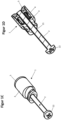
- Figure 1 comprehensively the Figures 1A-1D is a first embodiment of the assembly device according to the invention shown.
- Figure 1A a side view
- Figure 1B a longitudinal section, with the threaded rod not shown in section.
- the longitudinal section is also shown in an isometric view in Figure 1D
- Figure 1C a plan view of the embodiment in the assembled state is shown.
- the assembly device consists of a threaded bushing 1 and a threaded rod 2.
- the threaded rod is elongated along a longitudinal direction X and has a rod thread 21 extending around the longitudinal axis of the threaded rod 2 along a longitudinal axis that runs in the longitudinal direction X.
- the threaded rod also has a head element 22, which is designed as a screw head and has recesses that allow the use of a Phillips screwdriver to rotate the threaded rod about the longitudinal axis.
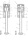
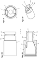
- the threaded bushing comprises a first bushing part 4 and a second bushing part in the form of a fixing part 3.
- the fixing part 3 is designed as a sleeve.
- the threaded bushing has a bushing thread 11 which is designed to correspond to the rod thread 21 and has the same thread pitch as the rod thread 21.
- the first bushing part has two sections 41, 42 which are connected by means of elastic webs 431, 432.
- the elastic webs 431, 432 run with a constant radius around the longitudinal axis L.
- the webs 431, 432 have a significantly smaller extension in the longitudinal direction X than perpendicular to the longitudinal direction X, wherein the webs 431, 432 have a constant cross-section circumferentially around the longitudinal axis.
- the sections 41, 42 both form the bushing thread 11.
- the height of the thread ridges of the bushing thread 11 changes in such a way that the height of the thread ridges in the holding state increases at least in sections towards the head element 22 of the threaded rod 2, which can be generally advantageous.
- the threaded rod 2 is guided through the threaded bushing 1, protruding through a through opening 39 into the fixing part 3 and further through a through opening 59 formed by a closure part 5.
- Figure 1 the assembly device is shown in the assembled state.
- the area of the bushing thread 11 facing away from the screw head 22 in the longitudinal direction X forms the first holding surface 101 of the threaded bushing 1, which is in contact with the corresponding first holding surface 201 of the threaded rod 2.
- the second holding surface 102 of the threaded bushing 1, which is arranged in the longitudinal direction X starting from the first holding surface 101 of the threaded bushing 1 in the direction of the screw head 22 next to the first holding surface 101 and is also formed by the bushing thread 11, is in contact with the rod thread 21.
- the rod thread 21 forms a second holding surface 202 of the threaded rod 2, which can be brought into contact with the second holding surface 102 of the threaded bushing 1 by transferring the assembly device into the holding state.
- at least one of the first retaining surfaces 101, 201 can form an intersection with one of the second retaining surfaces 102, 202 or, in particular, correspond thereto.
- the retaining surfaces correspond to the area of the threads 11, 21 which are in engagement with one another in the respective states. This area can, depending on the intended play of the thread pairing, include areas of the thread lands, in particular their flanks, as well as the thread root.
- the closure part 5 is connected to the fixing part 3 by means of a detachable snap-in connection.
- the snap-in connection is established in that a formed bead, which extends transversely to the longitudinal direction X circumferentially around the longitudinal axis, engages in a corresponding circumferential groove which is formed by the fixing part 3. While the closure part 5 and the fixing part 3 are separated from each other, the first bushing part 4 is removable.
- the through openings 39, 59 are each formed with at least one chamfer, which facilitates insertion of the threaded rod 2 into the respective through opening 39, 59.
- the first bushing part 4 is in an area of its two sections 41, 42 on the in Figure 1A tapered along the longitudinal direction on the side facing left.
- the two sections 41, 42 have, in a tapered region, the taper by means of a conical surface which is located radially outward to the longitudinal axis X and which is arranged at a taper angle with respect to the longitudinal axis.
- the fixing part 3 forms the pressing surfaces distributed around the circumference, which are also formed along the longitudinal direction X in such a way that the fixing part 3 tapers along the longitudinal direction X, the taper extending conically according to a taper angle between the longitudinal axis and the tapered surface.
- Stop surfaces are provided extending transversely to the longitudinal direction X and adjacent to the pressing surfaces, wherein the first bushing part 4, upon reaching the holding state, abuts the stop surfaces with correspondingly formed surfaces, wherein further rotation about the longitudinal axis along the direction of rotation along which the holding state was reached starting from the assembled state is blocked by the stop effect of the stop surfaces.
- the fixing part 3 has, at an end of its extension in the longitudinal direction facing away from the closure part 5, a first
- the second fastening section 342 and the third fastening section 343 are, as in particular from Figure 1C is elliptical with respect to its outer surface perpendicular to the longitudinal direction X. At least one radius of the ellipse exceeds the extension of the first fastening section 341 perpendicular to the longitudinal direction X, wherein the first fastening section 341, taking into account the through opening 39, has a substantially annular cross-section along the longitudinal direction X.
- the threaded bushing 1 can be connected to the wall of the cistern, or to a section connected to the wall, which is provided, for example, by a splash guard plate that is fixed to the wall and covers a maintenance opening provided in the wall, by passing the second fastening section 342 through and inserting the first fastening section 341 through and into the wall or the section connected to the wall, and by rotating the threaded bushing 1 relative to the wall of the cistern by approximately 90° about the longitudinal axis, wherein the second and the third fastening sections 342, 343 each bear against the wall or the section with a surface that extends primarily transversely to the longitudinal direction, the surfaces facing one another, wherein the first fastening section 341 lies in the wall, so that the threaded bushing 1 projects through the wall of the cistern.
- Figure 2 shows in Figure 2A the embodiment of the assembly device according to the invention in an assembled state and in Figure 2B in a hold state.
- Figure 2A shows the threaded rod 2, which is guided through the threaded bushing 1 and is in engagement with the bushing thread 11 with its rod thread 21 at the same height as the longitudinal direction of the elastic webs 431, 432.
- the holding state which is shown in Figure 2B is shown, can be achieved by rotating the threaded rod 2 relative to the fixing part 3 along a path of movement which runs around the longitudinal axis, wherein the first bushing part 4 can be rotated together with the threaded rod 2 relative to the fixing part 3, after the bushing part 4 has previously been displaced by means of the threaded rod 2 along the longitudinal direction X in such a way that its tapered section is in contact with the pressing surfaces 31 of the fixing part 3.
- the first bushing part 4 rests with its tapered region on the pressing surface 31 of the fixing part 3, wherein simultaneously with the rotating movement the sections 41, 42 of the first bushing part 4 move relative to one another, wherein a restoring force proportional to the rotating movement is formed by the elastic webs 431, 432.
- the region of the bushing thread 11 offset from the elastic webs 431, 432 in the longitudinal direction X which region has higher thread webs, engages with the rod thread 21.
- the first bushing part 4 is thus movable relative to the fixing part 3 over a movement distance which, in the present case, comprises a rotational movement over which the sections 41, 42 are moved towards one another perpendicular to the longitudinal direction X when the rotational movement is carried out from the assembled state to the held state, wherein the rotational movement can be absorbed by the threaded rod 2, since in the assembled state there is a sufficient frictional force between the threaded rod 2 and the first bushing part 4.
- the closure part 5 is not shown.
- the threaded webs of the rod thread 21 engage behind the threaded webs of the bushing thread 11 in such a way that a free displacement of the threaded rod 2 relative to the threaded bushing 3 is no longer possible without a thread-typical forced coupling with a rotational movement of the threaded bushing 1 relative to the threaded rod 2 about the longitudinal axis.
- the assembly device can be released from the holding state and brought into the assembly state by a twisting movement in the opposite direction of twisting of the threaded rod 2 and the first bushing part 4 relative to the fixing part 3.
- Figure 3 shows the fixing part of the threaded bushing 1 in various schematic diagrams, including a top view in Figure 3A , a representation of a section along the longitudinal direction in Figure 3B , a representation of a section perpendicular to the longitudinal direction X in Figure 3C and an isometric view in 3D figure .
- the closure part is not shown.
- the component is made in one piece as an injection-molded part.
- the through-opening 39 forms a chamfer, which allows easier insertion of the threaded rod 2 into the threaded bushing 1.
- the fastening sections 341, 342, 343 are arranged in the longitudinal direction X next to the area which receives the first bushing part 4.
- the fixing part has the pressing surfaces 31 on two radially opposite sides, which, as in Figure 3C can be seen, are arranged offset from one another in a transverse direction which is perpendicular to the longitudinal direction X.
- the pressing surface 31 is tapered and tapers towards the longitudinal axis with a taper angle, wherein the The taper angle increases in the direction of rotation, so that the sections 41, 42 are moved toward one another during the rotational movement that the first bushing part 4 performs relative to the fixing part 3 to achieve the holding state starting from the assembled state.
- the threaded bushing 1 forms a step.
- Figure 4 shows an embodiment of the system according to the invention comprising two mounting devices, which are designed according to the exemplary embodiment explained above and which are offset and spaced apart from one another perpendicular to the longitudinal direction X, a concealed unit designed as a cistern, and a cover plate designed as an actuating plate.
- the actuating plate comprises an actuating plate frame 80 and an actuating panel 81.
- the cistern comprises a splash guard plate 90, which is fixed in position to the wall of the cistern as intended.
- the threaded bushings 1 are each connected to the splash guard plate 90 of the cistern in a manner required for the operating state of the system.
- the threaded rods 2 are each guided through a respective passage of the
- Actuating plate frame 80 wherein the head element 22 of the threaded rod 2 with its extension transverse to the longitudinal direction X projects beyond the extension of the passage of the actuating plate frame 80, so that the actuating plate frame 80 can be pressed by the head element 22 against a pre-wall, not shown.
- the threaded rods 2 can each be inserted into the threaded bushing 1 by inserting them along the longitudinal direction X into the respective associated threaded bushing 1 without being twisted until the head elements 22 of the threaded rods 2 are on the actuator plate frame 80 of the Actuator plate. Subsequently, the threaded rods 2 are each rotated relative to the respectively assigned fixing part 3 fixed to the splash guard plate 90, whereby the holding state of the mounting devices is established, wherein by continuing the rotation in the same direction of rotation, due to the interaction of the rod thread and the bushing thread, a pressing force is generated from the head elements 22 onto the actuator plate frame 80 along the longitudinal direction X.
- the actuating panel 81 can be placed onto the actuator plate frame 80 along the longitudinal direction X and can be fixed to the actuator plate by means of snap connections.
Landscapes
- Engineering & Computer Science (AREA)
- General Engineering & Computer Science (AREA)
- Mechanical Engineering (AREA)
- Clamps And Clips (AREA)
- Connection Of Plates (AREA)
Applications Claiming Priority (2)
| Application Number | Priority Date | Filing Date | Title |
|---|---|---|---|
| DE102020106458.6A DE102020106458A1 (de) | 2020-03-10 | 2020-03-10 | Montageeinrichtung für Abdeckplatte |
| EP21157796.0A EP3879130B1 (fr) | 2020-03-10 | 2021-02-18 | Dispositif de montage pour plaque de recouvrement |
Related Parent Applications (1)
| Application Number | Title | Priority Date | Filing Date |
|---|---|---|---|
| EP21157796.0A Division EP3879130B1 (fr) | 2020-03-10 | 2021-02-18 | Dispositif de montage pour plaque de recouvrement |
Publications (2)
| Publication Number | Publication Date |
|---|---|
| EP4530487A2 true EP4530487A2 (fr) | 2025-04-02 |
| EP4530487A3 EP4530487A3 (fr) | 2025-06-25 |
Family
ID=74668653
Family Applications (2)
| Application Number | Title | Priority Date | Filing Date |
|---|---|---|---|
| EP21157796.0A Active EP3879130B1 (fr) | 2020-03-10 | 2021-02-18 | Dispositif de montage pour plaque de recouvrement |
| EP25157221.0A Pending EP4530487A3 (fr) | 2020-03-10 | 2021-02-18 | Procédé de fixation amovible d'une plaque de recouvrement sur une unité encastrée |
Family Applications Before (1)
| Application Number | Title | Priority Date | Filing Date |
|---|---|---|---|
| EP21157796.0A Active EP3879130B1 (fr) | 2020-03-10 | 2021-02-18 | Dispositif de montage pour plaque de recouvrement |
Country Status (3)
| Country | Link |
|---|---|
| EP (2) | EP3879130B1 (fr) |
| DE (1) | DE102020106458A1 (fr) |
| PL (1) | PL3879130T3 (fr) |
Family Cites Families (5)
| Publication number | Priority date | Publication date | Assignee | Title |
|---|---|---|---|---|
| FR2640336B1 (fr) * | 1988-12-12 | 1991-03-29 | Jouve Daniel | Ecrou rapide |
| GB9411313D0 (en) * | 1994-06-07 | 1994-07-27 | Hedley Purvis Ltd | Improved reaction nut |
| US6361260B1 (en) * | 2000-11-03 | 2002-03-26 | Wendell E. Schirrmacher | Quick locking fastener |
| DE202008007513U1 (de) * | 2008-06-05 | 2008-08-07 | Sanitärtechnik Eisenberg GmbH | Betätigungsvorrichtung für einen Sanitärgegenstand |
| DE102008042190A1 (de) | 2008-09-18 | 2010-03-25 | Globe Union Industrial Corp. | Schnell-Befestigungsmutter |
-
2020
- 2020-03-10 DE DE102020106458.6A patent/DE102020106458A1/de active Pending
-
2021
- 2021-02-18 EP EP21157796.0A patent/EP3879130B1/fr active Active
- 2021-02-18 PL PL21157796.0T patent/PL3879130T3/pl unknown
- 2021-02-18 EP EP25157221.0A patent/EP4530487A3/fr active Pending
Also Published As
| Publication number | Publication date |
|---|---|
| EP3879130A1 (fr) | 2021-09-15 |
| EP4530487A3 (fr) | 2025-06-25 |
| EP3879130C0 (fr) | 2025-02-12 |
| PL3879130T3 (pl) | 2025-06-16 |
| DE102020106458A1 (de) | 2021-09-16 |
| EP3879130B1 (fr) | 2025-02-12 |
Similar Documents
| Publication | Publication Date | Title |
|---|---|---|
| DE68903541T2 (de) | Stossbefestiger. | |
| DE3515306C2 (fr) | ||
| EP1961976B1 (fr) | Dispositif de fixation | |
| EP1297596B1 (fr) | Garniture de raccordement pourvue d'une bague elastique comme butee | |
| DE10229300B3 (de) | Verbindungssystem für Bauteile, insbesondere für Möbelteile | |
| EP1454071A1 (fr) | Ecrou de raccordement concu pour visser des elements de construction sur un composant de type plaque | |
| EP0059877A1 (fr) | Accouplement pour tuyaux à pression | |
| EP0206327B1 (fr) | Dispositif de connexion d'éléments tubulaires | |
| EP3004702B1 (fr) | Combination d'un boîtier et d'une soupape | |
| EP2742199B1 (fr) | Système de fixation pour fixer une pièce sur une rainure d'une fenêtre, d'une porte ou analogue | |
| WO2019214894A1 (fr) | Traversée de paroi | |
| EP3392418B1 (fr) | Système de fixation | |
| DE102019111237B4 (de) | Zweiteilige Schraubenmutter mit hoher Andrückkraft | |
| EP2102509B1 (fr) | Tirant et ensemble de modules assemblés par serrage à l'aide dudit tirant | |
| DE2056723A1 (de) | Türschild oder Rosette | |
| EP3879130B1 (fr) | Dispositif de montage pour plaque de recouvrement | |
| EP0791759A1 (fr) | Boulon à connexion rapide | |
| EP3282058A1 (fr) | Dispositif de fixation d'un composant sanitaire, en particulier d'un cadre de fixation pour une plaque d'actionnement de wc ou d'urinoir | |
| DE102022100210A1 (de) | Zweiteilige Überwurfmutter | |
| DE60017342T2 (de) | Befestigungsvorrichtung für Profile | |
| EP3926185A1 (fr) | Support mural | |
| EP4119737B1 (fr) | Dispositif de retenue en particulier pour l'évacuation des eaux des toitures plates | |
| AT514628B1 (de) | Griffbeschlag | |
| DE29919203U1 (de) | Justier- und adaptierbarer Systemwechselstift | |
| DE60016484T2 (de) | Verfahren und Befestigungsvorrichtung zur Montage von Türbeschlägen |
Legal Events
| Date | Code | Title | Description |
|---|---|---|---|
| PUAI | Public reference made under article 153(3) epc to a published international application that has entered the european phase |
Free format text: ORIGINAL CODE: 0009012 |
|
| STAA | Information on the status of an ep patent application or granted ep patent |
Free format text: STATUS: THE APPLICATION HAS BEEN PUBLISHED |
|
| AC | Divisional application: reference to earlier application |
Ref document number: 3879130 Country of ref document: EP Kind code of ref document: P |
|
| AK | Designated contracting states |
Kind code of ref document: A2 Designated state(s): AL AT BE BG CH CY CZ DE DK EE ES FI FR GB GR HR HU IE IS IT LI LT LU LV MC MK MT NL NO PL PT RO RS SE SI SK SM TR |
|
| REG | Reference to a national code |
Ref country code: DE Ref legal event code: R079 Free format text: PREVIOUS MAIN CLASS: F16B0037080000 Ipc: F16B0037040000 |
|
| PUAL | Search report despatched |
Free format text: ORIGINAL CODE: 0009013 |
|
| AK | Designated contracting states |
Kind code of ref document: A3 Designated state(s): AL AT BE BG CH CY CZ DE DK EE ES FI FR GB GR HR HU IE IS IT LI LT LU LV MC MK MT NL NO PL PT RO RS SE SI SK SM TR |
|
| RIC1 | Information provided on ipc code assigned before grant |
Ipc: E03D 5/02 20060101ALI20250516BHEP Ipc: F16B 37/08 20060101ALI20250516BHEP Ipc: F16B 37/04 20060101AFI20250516BHEP |
|
| STAA | Information on the status of an ep patent application or granted ep patent |
Free format text: STATUS: REQUEST FOR EXAMINATION WAS MADE |
|
| 17P | Request for examination filed |
Effective date: 20251223 |
|
| RAP3 | Party data changed (applicant data changed or rights of an application transferred) |
Owner name: TECE SE |