EP4530487A2 - Method for removably fixing a cover plate to a flush-mounted unit - Google Patents
Method for removably fixing a cover plate to a flush-mounted unit Download PDFInfo
- Publication number
- EP4530487A2 EP4530487A2 EP25157221.0A EP25157221A EP4530487A2 EP 4530487 A2 EP4530487 A2 EP 4530487A2 EP 25157221 A EP25157221 A EP 25157221A EP 4530487 A2 EP4530487 A2 EP 4530487A2
- Authority
- EP
- European Patent Office
- Prior art keywords
- bushing
- threaded
- threaded rod
- longitudinal direction
- relative
- Prior art date
- Legal status (The legal status is an assumption and is not a legal conclusion. Google has not performed a legal analysis and makes no representation as to the accuracy of the status listed.)
- Pending
Links
Images


Classifications
-
- F—MECHANICAL ENGINEERING; LIGHTING; HEATING; WEAPONS; BLASTING
- F16—ENGINEERING ELEMENTS AND UNITS; GENERAL MEASURES FOR PRODUCING AND MAINTAINING EFFECTIVE FUNCTIONING OF MACHINES OR INSTALLATIONS; THERMAL INSULATION IN GENERAL
- F16B—DEVICES FOR FASTENING OR SECURING CONSTRUCTIONAL ELEMENTS OR MACHINE PARTS TOGETHER, e.g. NAILS, BOLTS, CIRCLIPS, CLAMPS, CLIPS OR WEDGES; JOINTS OR JOINTING
- F16B37/00—Nuts or like thread-engaging members
- F16B37/08—Quickly-detachable or mountable nuts, e.g. consisting of two or more parts; Nuts movable along the bolt after tilting the nut
- F16B37/0807—Nuts engaged from the end of the bolt, e.g. axially slidable nuts
- F16B37/0864—Nuts engaged from the end of the bolt, e.g. axially slidable nuts with the threaded portions of the nut engaging the thread of the bolt by pressing or rotating an external retaining member such as a cap, a nut, a ring or a sleeve
-
- E—FIXED CONSTRUCTIONS
- E03—WATER SUPPLY; SEWERAGE
- E03D—WATER-CLOSETS OR URINALS WITH FLUSHING DEVICES; FLUSHING VALVES THEREFOR
- E03D5/00—Special constructions of flushing devices, e.g. closed flushing system
- E03D5/02—Special constructions of flushing devices, e.g. closed flushing system operated mechanically or hydraulically (or pneumatically) also details such as push buttons, levers and pull-card therefor
- E03D5/028—Pusher plates and actuating mechanisms for built-in cisterns
-
- F—MECHANICAL ENGINEERING; LIGHTING; HEATING; WEAPONS; BLASTING
- F16—ENGINEERING ELEMENTS AND UNITS; GENERAL MEASURES FOR PRODUCING AND MAINTAINING EFFECTIVE FUNCTIONING OF MACHINES OR INSTALLATIONS; THERMAL INSULATION IN GENERAL
- F16B—DEVICES FOR FASTENING OR SECURING CONSTRUCTIONAL ELEMENTS OR MACHINE PARTS TOGETHER, e.g. NAILS, BOLTS, CIRCLIPS, CLAMPS, CLIPS OR WEDGES; JOINTS OR JOINTING
- F16B37/00—Nuts or like thread-engaging members
- F16B37/04—Devices for fastening nuts to surfaces, e.g. sheets, plates
- F16B37/044—Nut cages
-
- F—MECHANICAL ENGINEERING; LIGHTING; HEATING; WEAPONS; BLASTING
- F16—ENGINEERING ELEMENTS AND UNITS; GENERAL MEASURES FOR PRODUCING AND MAINTAINING EFFECTIVE FUNCTIONING OF MACHINES OR INSTALLATIONS; THERMAL INSULATION IN GENERAL
- F16B—DEVICES FOR FASTENING OR SECURING CONSTRUCTIONAL ELEMENTS OR MACHINE PARTS TOGETHER, e.g. NAILS, BOLTS, CIRCLIPS, CLAMPS, CLIPS OR WEDGES; JOINTS OR JOINTING
- F16B37/00—Nuts or like thread-engaging members
- F16B37/08—Quickly-detachable or mountable nuts, e.g. consisting of two or more parts; Nuts movable along the bolt after tilting the nut
- F16B37/0807—Nuts engaged from the end of the bolt, e.g. axially slidable nuts
- F16B37/0821—Nuts engaged from the end of the bolt, e.g. axially slidable nuts in two halves pivotally connected
Definitions
- the invention relates to a mounting device, a system comprising the mounting device and a method for using the system for fixing a cover plate to a concealed unit, in particular to a wall of a cistern.
- the mounting devices are used to fix cover plates, which are used to conceal elements of concealed units of a sanitary installation, for example, elements of a concealed cistern, a concealed thermostat unit, or a concealed pipe connection point, relative to the concealed units.
- the cover plates serve to conceal the elements, but often also to implement additional functions.
- Such cover plates are therefore often designed as actuator plates that have actuation buttons via which the concealed unit can be operated.
- the cover plates are thus usually mounted on a false wall in such a way that they are accessible from a space defined by the false wall, thereby concealing a section of the concealed unit located behind the false wall.
- a pre-wall is to be understood in particular as a wall element which is arranged in front of another wall and is connected to it, forming a hollow space between the pre-wall and the wall.
- a cover plate designed as an actuation plate is usually provided, spaced separately from the cistern.
- the actuation plate is used to activate the functions of the cistern.
- the actuation plate usually has an actuation plate frame which is releasably fixed relative to the cistern, as well as an actuation panel with actuation buttons which are releasably fixed to the actuation plate frame.
- the actuation buttons are usually connected to a drain valve via actuation pins or electronics so that a flush can be triggered via them.
- the actuation plate is conventionally fixed to the cistern using appropriate connecting means.
- a generic cistern has a wall in which flush water is collected for a flush.
- the actuation plate is usually fixed relative to the wall, in particular directly or indirectly fixed to the wall. Preferably, it is attached to a splash guard plate, which is releasably fixed to the wall and closes an inspection opening provided in the wall.
- the section of the actuator plate via which the actuator plate is actuated, in particular the actuator plate, and the wall are usually spaced apart from each other in the operating state and fixed relative to each other by the corresponding connecting means.
- a flush-mounted unit usually has a wall section, for example, a sheet metal or plastic plate or a suitable profile, to which the cover plate is fixed using conventional connecting means.
- the cover plate in particular the described actuating plate of a cistern, covers a maintenance opening in the pre-wall.
- the cover plate can be loosened and removed from the maintenance opening in order to enable, in particular for maintenance personnel, access to the visually concealed elements of the concealed unit, in particular of the cistern, through the maintenance opening.
- the fixation of the cover plate, in particular of the actuating plate, relative to the wall of the cistern is therefore regularly loosened and restored after completion of the maintenance.
- the connecting means are therefore usually designed in such a way that they enable releasable fixation.
- the connecting means are generically designed as a mounting device comprising a threaded rod which extends with its longitudinal axis in a longitudinal direction and has a thread in particular along the predominant part of its longitudinal extent.
- the mounting device generically comprises a thread fixed to the concealed unit, in particular to the wall of the cistern, and formed corresponding to the thread of the threaded rod.
- the longitudinal extension of the threaded rod is understood to be the extension that runs along a longitudinal axis along which the threaded rod forms its thread, so that the thread runs around the longitudinal axis. The direction along this longitudinal axis is referred to as the longitudinal direction.
- the threaded rod is guided through a designated opening in the cover plate and screwed into the thread provided on the cistern, whereby a force is built up that applies the cover plate to the pre-wall and fixes it relative to the concealed unit, in particular to the wall of the cistern.
- at least one further mounting device is provided to support the fixation.
- These multiple mounting devices are usually spaced from one another in a direction perpendicular to the longitudinal direction, with the mounting devices preferably each having a distance from the center of the cover plate, relative to the same direction.
- the length of the threaded rod in generic mounting devices regularly exceeds a required minimum length, which corresponds to the distance between the cover plate and the concealed unit, in particular the actuator plate and the wall of the cistern. Because the distance between one side of the wall, to which the cover plate is to be fixed by the at least one mounting device, can vary depending on the room environment, a length of the threaded rod is usually provided that allows appropriate fixing even with an above-average distance between the actuator plate and the wall. In some cases, the length of the threaded rod exceeds the required minimum length by at least 50%, in particular at least 100%. As a result, during assembly, in order to establish the operating state, a comparatively time-consuming process of screwing the threaded rod into the corresponding thread on the concealed unit, in particular the cistern, is necessary.
- the object of the invention is to provide a mounting device and a method for fixing a cover plate to a flush-mounted unit, which at least partially eliminates at least some of the disadvantages of generic mounting devices.
- the mounting device comprises a threaded rod extending with its longitudinal axis in a longitudinal direction and a threaded bushing.
- the threaded rod is inserted into the threaded bushing fixed to the flush-mounted unit to realize an assembled state of the mounting device in which the threaded rod is received within a longitudinal extent by the threaded bushing and in which the threaded bushing and the threaded rod abut one another with mutually corresponding first holding surfaces to inhibit relative movement along the longitudinal direction and in which the threaded rod is displaceable along the longitudinal direction relative to the threaded bushing upon application of an external displacement force acting between the threaded rod and the threaded bushing in the longitudinal direction.
- At least two sections of the threaded bushing which extend over a same longitudinal section of the threaded bushing within the longitudinal extent, are moved towards each other by means of a movement, in particular rotation, of the threaded rod perpendicular to the longitudinal direction, thereby changing their relative position to each other in order to change the mutually corresponding holding surfaces with which the threaded bushing and the threaded rod abut each other, whereby a holding state of the assembly device is realized in which the threaded bushing and the threaded rod abut each other with mutually corresponding second holding surfaces, which are different from the first holding surfaces, and in which by an engagement of a rod thread running around the longitudinal axis of the threaded rod and a bushing thread of the threaded bushing corresponding to the rod thread, upon application of the external displacement force acting between the threaded rod and the threaded bushing in the longitudinal direction, a displacement of the threaded rod to Threaded bushing is avoided.
- the threaded rod preferably has a longitudinal extension length that is at least twice, in particular at least four times, in particular at least ten times, the longitudinal extension.
- the rod thread is preferably formed over at least 50%, in particular at least 70%, of the longitudinal extension length of the threaded rod.
- the threaded rod of the mounting device is rotated about its longitudinal axis, while the rod thread and the socket thread engage with each other, in particular thereby generating a fixing force which acts between the cover plate and the concealed unit, in particular thereby fixing the cover plate to a pre-wall behind which the concealed unit, in particular the cistern, in particular the wall of the cistern, is located.
- the threaded rod has a head element, wherein in the assembled state the threaded rod is inserted into the threaded bushing, in particular by a rotation-free displacement of the threaded rod and threaded bushing relative to one another, until the head element rests against the cover, wherein the holding state is then realized and the threaded rod is moved by rotation about its longitudinal axis in the longitudinal direction towards the threaded bushing, in that the rod thread and bushing thread engage with one another.
- the rotation takes place by more than 270°, in particular by more than 360°, in particular by a multiple of 360°.
- the rotation of the threaded rod applies a pressing force to the cover plate which increases during the course of the rotation and with which it is pressed against a prefabricated wall.
- the cover plate is designed as an actuating plate which has actuating buttons via which the flush-mounted unit can be actuated, wherein the cover plate is detachably mounted to a pre-wall by means of the mounting device such that it is accessible from a space delimited by the pre-wall, and in doing so conceals a section of the flush-mounted unit which is located behind the pre-wall, wherein the cover plate conceals a maintenance opening provided in the pre-wall. After the cover plate has been detached from the pre-wall, the flush-mounted unit is preferably accessible through the maintenance opening.
- the mounting device is reversibly brought from the mounted state to the held state and back from the held state to the mounted state.
- the cover plate is detachably fixed to the pre-wall by means of the mounting device and then detached from the pre-wall for maintenance purposes by means of the mounting device, thereby exposing the maintenance opening.
- an elastic connection is provided between the sections, which counteracts the movement of the sections relative to one another perpendicular to the longitudinal direction, carried out to realize the holding state starting from the assembled state, wherein the connection is formed in particular by at least one elastic web which runs perpendicular to the longitudinal direction.
- the movement of the sections relative to one another creates a restoring force which, when all forces acting on the sections are removed, causes a return to the assembled state.
- the sections are moved relative to one another starting from the assembled state in such a way that they are tilted relative to one another about a tilt axis which runs substantially perpendicular to the longitudinal direction, whereby an angle between the sections about the tilt axis.
- the sections of the threaded bushing are formed by a first bushing part, wherein the threaded bushing has a second bushing part designed as a fixing part, wherein, while realizing the movement of the sections relative to one another, starting from the assembled state to achieve the holding state, the first bushing part is moved relative to the fixing part over a movement distance within a longitudinal extension range.
- the first bushing part in the held state, rests against at least one stop surface formed by the fixing part, wherein the stop surface limits the mobility of the first bushing part relative to the fixing part and the change in the relative position of the sections of the first bushing part.
- the first bushing part is spaced from the stop surface in the assembled state and, starting from the assembled state, is brought into contact with the stop surface of the fixing part by a, in particular continuous, displacement movement relative to the fixing part.
- the displacement movement comprises a rotational movement about an axis of rotation running along the longitudinal direction, wherein the bushing part and the fixing part are configured to correspond to one another in such a way that, starting from the assembled state, the holding state is achieved by executing the rotational movement through a defined angle of rotation, which is in particular less than 270°, preferably less than 180°.
- the holding state is realized by rotating the threaded rod relative to the fixing part.
- the assembly device is, after realization of the holding state of the holding state into the assembly state by moving the first socket part relative to the fixing part by applying a release force, wherein the release force is applied to the first socket part relative to the fixing part by a rotational movement of the threaded rod.
- the cover is designed as an actuating plate and has an actuating plate frame and an actuating panel, wherein the threaded rod is passed through a passage of the actuating plate frame before the assembly state of the assembly device is realized and is then inserted into the threaded bushing upon realization of the assembly state.
- the actuating frame has at least two passages, wherein a threaded rod assigned to it is passed through each of the passages and is then inserted into a threaded bushing assigned to it.
- Each of the threaded rods and the threaded bushing assigned to it are part of a respective assembly device.
- each threaded rod and the threaded bushing assigned to it each form a respective assembly device.
- a mounting device for releasably fixing a cover plate relative to a concealed unit, in particular to the cistern, in particular the wall of the cistern which mounting device has a threaded rod and a threaded bushing.
- the threaded rod extends with its longitudinal axis in a longitudinal direction.
- the threaded rod is received within a longitudinal extent by the threaded bushing.
- the longitudinal extent is formed within a section of the longitudinal extent of the threaded rod.
- the longitudinal extent can be continuous.
- the longitudinal extent is preferably less than half, in particular less than a quarter of the longitudinal extent of the threaded rod, and is in particular between a tenth and a half of the longitudinal extent of the threaded rod.
- the threaded rod and threaded bushing can be arranged one inside the other in the assembled state and in the held state.
- the threaded rod and threaded bushing can of course also be arranged one inside the other in a further state of the assembly device that does not correspond to any of the aforementioned states, wherein a specific state designates a specific arrangement of the components of the assembly device relative to one another.
- the threaded rod has a rod thread that runs around the longitudinal axis of the threaded rod.
- the longitudinal axis of the threaded rod thus corresponds to the axis of rotation about which the threaded rod can be rotated in order to screw the rod thread into a corresponding thread and/or to release it from a screw connection with the corresponding thread.
- the threaded rod can be designed as a screw.
- the threaded rod can have a head element, in particular a screw head, that projects radially, i.e. perpendicular to the longitudinal direction, beyond the rod thread and is formed in particular at a longitudinal end of the threaded rod.
- the screw head is designed in the usual way, for example with an Allen, Phillips, hexagon, or Torx screw head, so that the threaded rod can be easily rotated using a tool.
- the head element can be provided for contact with the cover plate and have a surface for contact with the cover plate.
- the threaded bushing has a bushing thread.
- the bushing thread and the rod thread are each designed to correspond to one another, at least in sections.
- the rod thread can have at least 50%, in particular at least 70% of the longitudinal extension length of the threaded rod, in particular be designed to be continuously circumferential or to be circumferential in circumferential sections.
- the rod thread can have interruptions in the longitudinal direction along the longitudinal axis or be designed to be continuous in the longitudinal direction.
- the socket thread can be designed to be continuous or to be circumferential in circumferential sections.
- the socket thread can be designed to be interrupted or continuous in the longitudinal direction.
- the socket thread and the rod thread can engage with each other in the assembled state and in the held state, wherein they engage behind each other in particular to different depths in the held state and in the assembled state.
- the socket thread can only be formed by engagement with the corresponding rod thread, in particular in that the threaded socket has a deformable, in particular elastically deformable section, into which the rod thread can be screwed to form the socket thread.
- rod and bushing threads are present in the holding state and, in particular, also in the assembled state, whereby preferably the threaded rod in isolation and, in particular, the threaded bushing in isolation, i.e., as a component property without a mandatory connection to another component, has a corresponding thread.
- the rod thread or bushing thread can only be formed through engagement with the corresponding bushing thread or rod thread.
- the threaded rod and threaded bushing When an external displacement force is applied, the threaded rod and threaded bushing can be displaced relative to each other in the longitudinal direction in a preferably non-destructive and reversible manner in the assembled state.
- the displacement force acts between the threaded rod and the threaded bushing and has a predetermined amount.
- Displacement generally refers to a movement, in particular a translational movement, of two bodies relative to one another that can be carried out decoupled from other movements.
- displacement refers to a movement of two bodies relative to one another that does not have a forced coupling with any other movement. In the held state, such a forced coupling is present and includes, in particular, the forced coupling of a rotation and a translation.
- the threaded bushing and the threaded rod bear against one another with corresponding holding surfaces to inhibit relative movement along the longitudinal direction, in particular within the longitudinal extent.
- the action of a force along the longitudinal direction is inhibited.
- the threaded rod and the threaded bushing are designed to correspond to one another in such a way that a first holding force acts in the assembled state in the opposite direction to the external displacement force acting in the longitudinal direction, wherein, if the external displacement force does not exceed the amount of a first holding force, the displacement of the threaded rod and the threaded bushing along the longitudinal direction relative to one another is avoided, and when the external Displacement force: if the external displacement force exceeds the magnitude of the first holding force, the threaded rod and threaded bushing are displaceable relative to one another along the longitudinal direction, wherein in a held state, a second holding force is provided by an interlocking of a rod thread running around the longitudinal axis of the threaded rod and a bushing thread corresponding to the rod thread, which second holding force is greater than the first holding force, so that when the external displacement force is applied, a displacement of the threaded rod relative to the threaded bushing is avoided and such a displacement is only possible when a displacement
- the application of such a displacement force exceeding the second holding force inevitably leads to damage to the mounting device.
- the first holding force can be less than 50%, in particular less than 30%, in particular less than 20% of the second holding force.
- the displacement force is applied externally, which excludes the possibility that the displacement force is formed solely by forces of the static operative connection of the sections and/or components and/or elements of the mounting device.
- the forces of the static active connection can be shear forces and/or caused by residual stresses.
- the external displacement force can be applied, in particular, by a human's physical force. In particular, the external displacement force can be applied by auxiliary devices.
- the threaded bushing and the threaded rod are in contact with each other with the corresponding holding surfaces.
- the threaded bushing and the threaded rod are in contact with each other with the first correspondingly formed Retaining surfaces abut one another.
- the threaded rod has a first retaining surface of the threaded rod and the threaded bushing has a first retaining surface of the threaded bushing, wherein both first retaining surfaces correspond to one another and abut one another.
- At least one of the first retaining surfaces has at least a section of the bushing thread or the rod thread, wherein this first retaining surface abuts the other first retaining surface, in particular with thread webs of the bushing thread or the rod thread.
- the first retaining surface formed by the threaded rod has a section of the threaded rod and the first retaining surface formed by the threaded bushing has a section of the bushing thread, wherein in the assembled state, the threads abut one another with their thread webs within this section. In the held state, the threaded bushing and the threaded rod abut with second retaining surfaces formed in a corresponding manner.
- the pair of corresponding first retaining surfaces in the assembled state differs from the pair of corresponding second retaining surfaces in the held state in that at least one of the first retaining surfaces differs from one of the second retaining surfaces.
- all first holding surfaces differ from all second holding surfaces, wherein it can be provided that one of the first holding surfaces forms a part of one of the second holding surfaces.
- the holding state can be established by bringing the threaded rod and the threaded bushing from the contact of the first holding surfaces to one another to the contact of the second holding surfaces to one another.
- the threaded bushing has at least two, in particular exactly two, sections that extend over a same longitudinal section of the threaded bushing.
- the longitudinal section is a section of the threaded bushing that in the The assembled state or holding state corresponds to a section of the extension of the threaded bushing in the longitudinal direction.
- the at least two sections can extend completely over the same longitudinal section.
- the bushing thread and/or the second holding surface and/or the first holding surface of the threaded bushing is preferably formed by the sections, wherein at least one of the sections, in particular the sections, forms or form the bushing thread.
- the sections extend parallel to the longitudinal extent of the threaded rod in the assembled state and/or holding state.
- the at least two sections are preferably spaced apart from one another perpendicular to the longitudinal direction in the assembled state and/or holding state, in particular opposite one another, and spaced apart from the longitudinal axis of the threaded rod and in particular eccentrically arranged to the longitudinal axis. In the assembled state and/or holding state, they are preferably distributed circumferentially around the threaded rod.
- the at least two sections preferably form the second holding surface of the threaded bushing and particularly preferably the first holding surface of the threaded bushing.
- the at least two sections are also movable relative to one another along a perpendicular to the longitudinal direction.
- the at least two sections are movable relative to each other.
- the two sections can have a smaller distance from each other perpendicular to the longitudinal axis in the holding state compared to their relative position in the assembled state.
- the movement of the sections between the assembled state and the holding state preferably takes place continuously.
- an engagement volume with which the threaded rod and the threaded bushing engage in the holding state increases compared to the assembled state.
- the portion of the holding surface of one component that rests perpendicular to the longitudinal direction against the corresponding holding surface of the other component (threaded rod or threaded bushing).
- the bushing thread is preferably designed in the form of an internal thread.
- the threaded rod has the rod thread in the form of an external thread.
- the threaded rod can be made of metal.
- the threaded rod and/or the threaded bushing can be made of plastic, in particular of thermoplastic.
- the threaded bushing can be designed in several parts.
- the threaded bushing preferably comprises fewer than ten, particularly preferably fewer than five parts.
- parts refer to elements that are separate components that can in particular be arranged in an assembly.
- the threaded bushing can comprise exclusively plastic parts.
- the threaded rod can be designed in one piece.
- the threaded rod can have a head element for contact with the cover plate.
- the at least two sections preferably have a smaller extension in the longitudinal direction than the threaded bushing, preferably less than 70%, preferably less than 50% of the longitudinal extension length of the threaded bushing.
- the mounting device can preferably be brought reversibly from the mounted state into the holding state and from the holding state back into the mounted state.
- the threaded rod can be moved from the holding state by rotation about its longitudinal axis in the longitudinal direction towards the threaded bushing, in that the rod thread and bushing thread engage with each other, wherein the rotation can preferably take place by more than 270°, in particular more than 360°, in particular by a multiple of 360°.
- an increasing pressing force is applied to the cover plate during rotation, pressing it against a prefabricated wall.
- the mounting device according to the invention offers a number of advantages compared to generic mounting devices.
- the mounting device according to the invention makes it possible to attach the cover plate to the concealed unit, in particular to the wall of the cistern, or to detach it from the concealed unit considerably more quickly.
- no additional gear elements are required for attachment and detachment.
- the threaded rod can be adjusted particularly quickly and easily to the length that corresponds in particular to a required distance between the cover plate and the concealed unit, which is determined in particular by the distance of the wall from the room side of the pre-wall. In the installed state, the threaded rod and threaded bushing can be positioned relative to one another simply by sliding them non-rotatably relative to one another.
- the fixing can preferably be achieved by means of a particularly small angle of rotation.
- the mounting device according to the invention enables fixing that is at least as secure as generic mounting devices.
- the mounting device according to the invention enables very simple and error-free fixing.
- the object according to the invention is characterized by a small number of required components, which are also cost-effective can be manufactured.
- the mounting device according to the invention can therefore be manufactured and installed more cost-effectively than generic mounting devices.
- the components can be manufactured using easily scalable, proven manufacturing processes.
- the function of the mounting device is already guaranteed if all components are made of the same material.
- the mounting device also offers the advantage of space-saving installation of the cistern in the pre-wall, which means that a particularly small distance between the pre-wall and the wall is required. This simplifies and accelerates maintenance processes and significantly reduces downtimes of the respective sanitary facilities. Fastening using the mounting device can be carried out without special tools and by untrained personnel.
- the simple design of the mounting device makes it particularly fail-safe. Should defects due to wear and tear nevertheless occur, the affected components can be easily replaced.
- the threaded bushing is designed in several parts.
- the sections of the threaded bushing are formed by a first bushing part, wherein the threaded bushing has a second bushing part which is designed as a fixing section.
- the first bushing part is movable relative to the fixing part within a, in particular predefined, longitudinal extension region.
- the longitudinal extension region is a region within the extension of the threaded bushing in the longitudinal direction.
- the threaded bushing has means for restricting the mobility of the first bushing part relative to the fixing part at the respective boundaries of the longitudinal extension region in the longitudinal direction.
- Within the The first bushing part is movable relative to the fixing part over a distance of movement within the longitudinal extension region.
- the distance of movement is a distance that can be covered by a movement and is defined between an initial position and an end position.
- the distance of movement can be a distance along a rotational movement, in particular along a rotational movement about the longitudinal axis, in particular of the first bushing part relative to the fixing part.
- the rotational movement can be superimposed by a further movement component of the sections relative to one another.
- the first bushing part can be tapered within the longitudinal extension region.
- the fixing part can be tapered at least in one section.
- both the fixing part and the first bushing part can be tapered, wherein particularly preferably the first bushing part and the fixing part each have a taper angle, i.e. an angle of its surface to the longitudinal axis, which differs from the respective other taper angle.
- the fixing section has a larger taper angle than the first bushing part, wherein both taper angles relate to the longitudinal axis.
- the first bushing part and/or the fixing part can be tapered in such a way that the respective taper angle is constant, in particular along the respective circumference of its surface.
- the respective taper angle can change along the respective circumference.
- the first bushing part and/or the fixing part has a continuously changing taper angle within the longitudinal extension region along the movement path.
- the tapered design can be stepped, wherein within the tapered region, taper angles between preferably 0° and 90° are possible.
- the first bushing part is pressed against a pressing surface of the fixing part with a pressing force acting perpendicular to the longitudinal direction.
- the pressing surface can be formed by pressing surface sections which are in particular spaced apart from one another.
- the pressing force can have a force component in the longitudinal direction, so that the resulting pressing force lies at an angle between the longitudinal axis and a plane perpendicular to the longitudinal axis.
- the contact of the first bushing part, in particular of the sections of the first bushing part, against the pressing surface of the fixing part preferably determines the relative position of the sections to one another, in particular in a direction perpendicular to the longitudinal axis.
- the relative position of the sections when the first bushing part is in contact with the pressing surface of the fixing part can differ from a relative position of the sections to one another in which there is no contact with the fixing part.
- the determination of the relative position of the sections to one another by the contact of the first bushing part against the fixing part takes place with the development of the pressing force.
- a movement of the first bushing part relative to the fixing part along a predetermined direction of movement within the movement path within the longitudinal extension region directly changes the relative position of the sections of the bushing part to one another.
- the change in the relative position of the sections occurs continuously, particularly preferably continuously and preferably directly proportional to the course of the movement path, along the movement path.
- the sections are connected to each other by an elastic connection.
- the elastic connection here means that Connecting means for connecting the sections are connected to the sections, in particular are connected in one piece, which have elastic material properties.
- Elastic material properties specifically include the property of being able to carry out a reversible deformation under the action of an external force starting from an initial position, developing a restoring force.
- the restoring force is dependent on, in particular proportional to, the deformation.
- the deformation can be reversed by the restoring force when the external force is removed.
- This reversible deformation can be subject to hysteresis, so that a return from the deformation to the initial position occurs with a difference compared to the original initial position.
- the initial position here corresponds to the assembled state.
- the elastic connection is provided in such a way that upon deflection starting from the assembled state until the holding state is reached, based on the shape of the first bushing part present in each of the states, the restoring force brings about a return to the assembled state when all forces acting on the sections are eliminated.
- the first bushing part comprising the sections and the elastic connection is formed in one piece, in particular made in one piece from plastic, in particular by injection molding.
- the elastic connection comprises a connecting element produced separately from the sections, which is subsequently connected to the sections, wherein, for example, the elastic connection comprises an elastic ring that is slipped over the sections.
- the Movement can result from the movement of the first bushing part relative to the fixing part within a predetermined direction of movement along the movement path.
- the elastic connection between the sections counteracts, in particular, a movement perpendicular to the longitudinal direction of the sections relative to one another, starting from the assembled state and moving towards the held state, thereby forming the restoring force.
- the connection can be formed by at least one elastic web which runs perpendicular to the longitudinal direction.
- the at least one elastic web can run partially in the longitudinal direction.
- the at least one elastic web can have a greater extent perpendicular to the longitudinal direction than in the longitudinal direction.
- the extension of the at least one elastic web in the longitudinal direction can run over less than 30%, preferably less than 20%, particularly preferably over less than 10% of the longitudinal extension of the sections it connects.
- the cross section of the at least one web is smaller than its length.
- the cross section is less than half, in particular less than a third of the length of the web.
- the extension of the elastic web in the longitudinal direction can be interrupted in sections, wherein a plurality of web segments spaced apart in the longitudinal direction are formed.
- the elastic connection, particularly preferably the elastic web(s) is spaced apart from the pressing surface in the assembled state.
- the at least one web is formed integrally with at least one of the sections.
- the elastic connection is arranged outside the center point of the two sections.
- the elastic connection is spaced apart in the longitudinal direction from the center point of each of the at least two sections.
- the elastic connection is arranged in a region of the sections which is on a from the tapered region.
- the sections are in particular movable relative to one another in such a way that the sections can be tilted relative to one another about a tilt axis which runs substantially perpendicular to the longitudinal axis. Tilting leads to a change in the angle between the sections, in particular opposite ones, about the tilt axis.
- the sections are in particular tilted relative to one another compared to their position in the assembled state when the first bushing part is in contact with the pressing surface of the fixing section.
- the elastic connection is preferably formed by at least two webs, wherein each of the webs can have a selection of the properties explained above with reference to a web.
- the first bushing part in the holding state, rests at least partially, in particular with one of its sections, against a stop surface.
- the fixing part has the stop surface.
- the stop surface limits the mobility of the first bushing part relative to the fixing part, in particular along the movement path.
- the mobility is limited in particular in one direction of movement along the movement path, in particular in the direction of movement from the mounted state to the holding state, while preferably a movement in the opposite direction of movement is unlimited. Due to the limited mobility of the first bushing part relative to the fixing part, the mobility of the sections of the first bushing part is limited. In particular, a rotation of the first bushing part relative to the fixing part is limited when the first bushing part rests against the pressing surface of the fixing part.
- At least a rotational movement along the longitudinal axis is unlimited when the first bushing part is not the stop surface and/or is spaced apart from the stop surface in a longitudinal direction and/or perpendicular to the longitudinal direction from the fixing part.
- the stop surface limits mobility only in the holding state.
- the stop surface can be part of the pressing surface, in particular if the pressing surface has a variable distance from the longitudinal axis.
- the first bushing part can form a first counter surface corresponding to the stop surface.
- the stop surface can be functionally composed of several surfaces which together have a stop effect. The stop effect limits the mobility of the first bushing part relative to the fixing part.
- the first bushing part in particular the sections, particularly preferably a surface formed by at least one of the sections corresponding to the stop surface, bears against the stop surface in the holding state.
- the first bushing part is spaced from the stop surface in the assembled state.
- the first bushing part can be brought into contact with the stop surface by a sliding movement relative to the fixing part, starting from the assembled state.
- the sliding movement runs in particular along the movement path starting from the assembled state towards the holding state, wherein the sliding movement is preferably a continuous movement.
- the sliding movement can be a continuous movement.
- the holding state can be created by the sliding movement, wherein in the holding state, in particular, the first bushing part rests against the stop surface.
- the stop surface lies outside the pressing surface.
- the stop surface extends exclusively outside the pressing surface. along a greater distance from the longitudinal axis than a point on the pressing surface closest to the longitudinal axis.
- the first bushing part preferably bears against the stop surface at least with linear contact, in particular with surface contact.
- the stop surface can be arranged in a region in the longitudinal direction in which the fixing part is tapered.
- the stop surface preferably extends predominantly perpendicular to the longitudinal direction.
- the surface normal of the stop surface can have an angle of >0°, in particular >30°, relative to the surface section of the pressing surface over which more than 50%, in particular more than 70%, of the pressing force is applied in the held state.
- the first bushing part preferably bears with its first counter-surface against a second counter-surface of the fixing part, which counter-surface runs perpendicular to the longitudinal direction.
- the surface normal of the first counter-surface can point in a specific direction. In particular, the surface normals of the first counter-surface and the second counter-surface are arranged parallel to one another in the held state.
- the elastic connection is arranged closer to the longitudinal end of the first bushing part or sections, which is located on the side facing away from the mating surface in the longitudinal direction.
- the stop surface can be designed as a functional element with locking and/or inhibiting properties.
- the functional element can comprise an elastic element, which in particular reduces its restoring force upon engagement with the respective mating surface.
- the displacement movement by which the first bushing part can be brought into contact with the stop surface of the fixing part starting from the assembled state relative to the fixing part comprises a rotary movement.
- the rotary movement occurs about a rotational axis running along a longitudinal direction.
- the rotational axis can correspond to the longitudinal axis.
- the rotational axis can deviate from the longitudinal axis by an angle, in particular of ⁇ 20°, in particular ⁇ 5°, wherein the angle refers to a rotation starting from the longitudinal axis about an axis which runs perpendicular to the longitudinal axis.
- the displacement movement can comprise further movement components which do not correspond to the rotational movement about the rotational axis in the longitudinal direction and are in particular translational.
- the first bushing part and the fixing part are preferably designed to correspond to one another in such a way that, starting from the assembled state, the holding state can be achieved by performing the rotational movement through a defined angle of rotation.
- the angle of rotation refers to an angle by which the first bushing part can be rotated relative to the fixing section to achieve the holding state, starting from a position in which the mounting device is in the assembled state.
- the angle of rotation refers in particular to a rotational movement component of the rotational movement which runs around the longitudinal axis.
- the angle of rotation is in particular less than 270°, preferably less than 180°. In particular, the angle of rotation lies within a range of 30° and 270°, preferably in a range of 30° and 180°.
- the rotational movement can be a spiral movement, in which a rotation and a movement of the sections relative to one another overlap in such a way that the movement path runs along a flat spiral.
- the spiral movement can be provided with a continuous, in particular continuous, preferably uninterrupted course.
- further rotational movements are possible which are unlimited with regard to their angle of rotation, wherein the two sections, when executing these further rotational movements, are between the first and fixing part do not touch the pressing surface.
- the threaded bushing has an anti-rotation device that prevents rotation of the fixing part and the first bushing part relative to one another, wherein rotation about an axis which corresponds in particular to the longitudinal axis, but at least runs along the longitudinal axis, is prevented.
- the anti-rotation device prevents rotation at least in one direction about the longitudinal axis, in particular in both directions about the longitudinal axis.
- the first bushing part has a part of the anti-rotation device that is functionally relevant for the anti-rotation device, in particular the anti-rotation device.
- the fixing part can have a region corresponding to the anti-rotation device.
- the anti-rotation device is preferably in the held state, and in particular also in the assembled state, in contact with a corresponding surface and/or edge formed by the first or second bushing part that does not have the anti-rotation device.
- the anti-rotation device is formed at least along a quarter, in particular along the entire longitudinal extension region of the first bushing part.
- the first bushing part with the correspondingly designed region is engaged in any state with the anti-rotation device.
- the anti-rotation device is designed such that the correspondingly designed region is guided in the anti-rotation device along the longitudinal direction.
- the anti-rotation device can be designed as a groove into which the correspondingly designed region engages.
- the anti-rotation device can be designed such that rotation about the axis within a defined angular range is permitted and exceeding the angular range is prevented by limiting devices.
- the mounting device is designed to be movable relative to the fixing part, starting from the holding state, by applying a release force to the first socket part, and in particular to be brought from the holding state into the mounted state.
- the mounting device can be released from the holding state by applying a release force.
- the release force can be introduced relative to the fixing part via the threaded rod.
- the release force can be applied as an external force.
- the external force can be applied as a torque, in particular to the threaded rod, and can be converted into a release force over a defined radius, so that the release force can be applied by a rotational movement of the threaded rod relative to the fixing part.
- a relative movement between the first socket part and the fixing part can be generated by applying a release force, wherein the release force exceeds a first minimum force.
- the first minimum force corresponds to a sum of holding force components that act counter to the release force and in particular comprises a static friction force between the first socket part and the fixing part.
- the static friction force is a frictional force that must be overcome in order to generate a relative movement of the first bushing part and the fixing part starting from a rest position.
- the first bushing part is preferably detachable from the fixing section, wherein in particular the first bushing section and the threaded rod do not perform any relative movement to each other during the release.
- the threaded rod is synchronized with the movement of the first bushing part starting from the Holding state into the assembled state.
- the force for generating a relative movement between the first bushing part and the fixing section is deliberately lower than for generating a relative movement between the first bushing part and the threaded rod.
- the assembled state can be achieved by rotating the threaded rod relative to the fixing part, in particular exclusively by rotating it.
- the threaded rod is preferably not displaceable relative to the first bushing part while maintaining the holding state, without rotating the threaded rod about its longitudinal axis relative to the first bushing part.
- the first bushing part can be moved relative to the fixing part along the movement path, in particular by means of a rotational movement which is opposite to the rotational movement for moving from the assembled state into the holding state.
- the angle between the relative position of the first bushing part and the fixing part corresponds to the angle of rotation of the rotational movement by means of which the holding state can be achieved starting from the assembled state.
- the first bushing section is movable relative to the fixing part by means of a return displacement movement directed opposite to the displacement movement, wherein the opposite return displacement movement comprises a rotational movement about a rotational axis running along the longitudinal direction, wherein the bushing part and the fixing part are designed to correspond to one another in such a way that, starting from the holding state, the assembly state can be reached by performing the rotational movement through a defined angle of rotation.
- the defined angle of rotation is in particular less than 270°, preferably less than 180°.
- the angle of rotation by which the rotational movement to reach the assembly state starting from Holding state has to take place, the angle of rotation by which the rotational movement can be carried out to reach the holding state starting from the assembled state.
- the holding state can be achieved starting from the assembled state by rotating the threaded rod relative to the fixing section.
- the return displacement movement corresponds exactly to a reversal of the displacement movement.
- the assembly device is designed such that the displacement movement and the return displacement movement can be carried out reversibly one after the other as often as desired.
- the assembly device is preferably designed such that it is possible to change reversibly between the assembled state and the holding state as often as desired.
- At least one of the sections of the first bushing part forms the bushing thread.
- at least one section has no bushing thread.
- the thread depth of the bushing thread preferably changes along the longitudinal direction, i.e., depending on the longitudinal direction.
- the bushing thread has a smaller thread depth at one end of its extension along the longitudinal direction than at an opposite end in the longitudinal direction.
- the bushing thread has a greater thread depth in a second region, which is further spaced from the elastic connection between the sections in the longitudinal direction, than in a first region, which is less far spaced from the elastic connection between the sections in the longitudinal direction, wherein preferably the first holding surface of the threaded bushing lies in the first region and the second holding surface of the threaded bushing lies in the second region.
- the bushing thread can have a constant thread depth in certain sections.
- the bushing thread can have a constant thread pitch, which corresponds in particular to the thread pitch of the rod thread.
- the thread depth of the bushing thread changes along the longitudinal direction in the section of the longitudinal extension area in which the fixing part and the first bushing part are located during their movement relative to each other along the movement path.
- the threaded bushing is designed such that it has a first fastening section and a second fastening section, which are particularly suitable for fastening the threaded bushing to the concealed unit, in particular to a wall section of the concealed unit, in particular to the wall of the cistern.
- the wall section is a section of a wall formed by the concealed unit, for example by a plate-shaped section, wherein the wall section preferably adjoins a cavity along the longitudinal direction both on its front side, from which the threaded bushing can be fixed to the wall section, and on its rear side, so that, on the one hand, the threaded rod can be guided to the threaded bushing through the cavity provided on the front side, and, on the other hand, the threaded bushing can be easily fixed to the wall section through the cavity provided on the rear side.
- the first and second fastening sections are directly adjacent to one another.
- the first fastening section has an extension in an extension direction running perpendicular to the longitudinal direction, wherein this extension corresponds to an extension of the second fastening section in, in particular, the same
- the first and second fastening sections each lie directly against one another at one end of their extension in the longitudinal direction.
- the second fastening section forms, in particular, a longitudinal end of the threaded bushing.
- the first fastening section forms a constant cross-section along the longitudinal direction.
- the first fastening section forms, along the longitudinal direction, a cross-section that is symmetrical, in particular rotationally symmetrical, with respect to the longitudinal axis.
- the second fastening section forms a contact surface for contact in the longitudinal direction on the wall section of the concealed unit, in particular on the wall of the cistern or a section of the cistern fastened to the wall, for example on the splash guard plate, which extends, in particular, perpendicular to the longitudinal direction.
- the contact surface can have one or more projections and/or recesses which, in contact with corresponding surfaces of the wall section or the wall or the section of the cistern, inhibit or block the mobility of the threaded bushing relative to the wall of the cistern, in particular a rotational mobility about the longitudinal axis of the threaded bushing and wall relative to one another.
- a pressing force acts between at least one fastening section and the wall section or the wall.
- the pressing force can further generate a frictional force between the contact surface and the wall section or the wall or section of the cistern, which inhibits rotational mobility about the longitudinal axis of the threaded bushing and the wall relative to each other.
- the first fastening section borders at one end, in particular at both ends of its extension in Longitudinal direction to a section whose extension perpendicular to the longitudinal direction it falls short of.
- the first fastening section is arranged along the longitudinal direction between the second and a third fastening section, wherein the second fastening section has the contact surface and the third fastening section has a further contact surface for contacting the wall section of the concealed unit or the wall of the cistern.
- the pressing force acts between the contact surface of the second fastening section and the wall section or the wall or the surface section, and the contact surface of the third fastening section and the wall section or the wall or the section.
- the third fastening section can form a longitudinal end of the threaded bushing, in particular of the fixing part of the threaded bushing, at the end of the threaded bushing opposite the second contact surface in the longitudinal direction.
- the mounting device can be provided in one embodiment as part of a set comprising the mounting device, a concealed unit, in particular a cistern, and a cover plate, in particular an actuating plate for actuating the cistern, wherein the cover plate has a device for fastening the threaded rod, in particular at least one recess for passing the threaded rod through the cover plate in the direction of its longitudinal axis.
- the threaded rod can preferably be placed for longitudinal contact with a corresponding surface of the actuating plate with a contact surface that extends transversely to the longitudinal direction.
- the threaded bushing is preferably formed along its longitudinal axis by a section of the concealed unit, in particular, the above-described wall section, in particular through a section of the cistern, in particular the wall of the cistern, and in particular by means of a rotational movement about its longitudinal axis relative to the concealed unit, in particular in a form-fitting manner.
- the preferably form-fitting fastening can be produced in particular by the threaded bushing being able to be placed on the fastening section with the contact surface of the second fastening section, in particular also with the contact surface of the third fastening section. This prevents any displacement of the threaded bushing relative to the cistern, or in particular to the wall of the cistern, along the longitudinal axis.
- the first bushing part of the threaded bushing is arranged in the fixing part, so that the fixing part extends around the first bushing part and in particular encloses the predefined longitudinal extension region.
- the fixing part is preferably designed in the manner of a sleeve, wherein the sleeve is designed as a hollow body stretched elongately along the longitudinal direction, which, at least in the assembled and held state, completely encloses the first bushing part at least in a region that is spaced from the longitudinal axis transversely to the longitudinal direction and, in particular, at least at a distance that corresponds to the extension of the threaded rod transversely to the longitudinal direction.
- the fixing part can form a receiving space for the first bushing part, arranged in particular symmetrically about the longitudinal axis, wherein the receiving space preferably extends continuously and in the longitudinal direction in a region that exceeds the longitudinal extension of the first bushing part and preferably in Longitudinally, it includes the first socket part.
- the first socket part is preferably arranged in the fixing part, at least in the assembled and held state.
- the first socket part is oriented, in particular with respect to its longitudinal axis, parallel to the longitudinal axis of the fixing part.
- the threaded rod and threaded bushing form threads on the corresponding holding surfaces, particularly in the held state.
- Both threads have thread ridges at least in sections, particularly at least in the held state.
- the thread ridges of the threads interlock in the held state, so that there is a positive connection in the longitudinal direction.
- the thread ridges engage behind one another in the longitudinal direction.
- the thread ridges each have an active and a passive thread flank, both of which extend predominantly transversely to the longitudinal direction.
- the active thread flanks abut one another in the held state.
- the active thread flanks abut one another over a smaller area in the assembled state than in the held state.
- the thread ridges interlock further in the held state than in the assembled state.
- the thread ridges engage further behind one another in the held state than in the assembled state.
- the thread of the holding surfaces of the threaded bushing is formed by the first bushing part.
- the thread preferably extends over the entire longitudinal extent of the first bushing part.
- the thread of the threaded rod engages in the assembled state in a first threaded region of the thread of the first bushing part, which is spaced further in the longitudinal direction from the pressing surfaces with which the fixing part bears against the first bushing part in the holding state, than a second threaded region of the thread of the first bushing part.
- the second threaded region is further spaced in the longitudinal direction from the elastic connections, in particular the elastic webs, than the first threaded region.
- the thread webs of the first threaded region have a smaller extension transverse to the longitudinal direction than the thread webs of the second threaded region.
- the second threaded region has thread flanks with a greater extension transverse to the longitudinal direction than the first threaded region.
- the thread of the threaded rod engages in the second threaded region of the thread of the first bushing part in the held state.
- the threads are standard threads, in particular metric standard threads, wherein in particular the thread of the threaded bush deviates from the specifications of the standard for the standard thread with regard to the extension of the thread web transverse to the longitudinal direction.
- the threaded bushing has a through-opening at each of its longitudinal ends.
- the threaded bushing has exactly two through-openings.
- the respective through-opening has a through-opening axis which runs through the through-opening and in particular represents an axis of symmetry of the through-opening, about which the through-opening is preferably rotationally symmetrical.
- the through-openings are arranged relative to one another in such a way that the through-opening axes are coaxial with one another.
- the through-openings are arranged in such a way that the through-opening axes form a common through-axis which runs in particular in the longitudinal direction, preferably along the longitudinal axis.
- At least one through-opening is spaced apart in the holding state in the longitudinal direction by more than 10%, preferably more than 25% of the longitudinal extent of the socket thread or in particular of the first socket part.
- the through-openings extend transversely to their feed-through axis over a radius which exceeds the thread radius of the threaded rod.
- the feed-through openings are formed in alignment with the threaded rod in the assembled state and in the holding state.
- at least one of the through-openings has, at at least one end of its extension in the longitudinal direction, a region in which the extension transversely to the longitudinal direction, in particular along an opening angle emanating from the longitudinal axis, which is preferably greater than 20°, in particular greater than 40°, in particular less than 80°, increases along the longitudinal direction.
- at least one of the through-openings has a chamfer formed at at least one end of its extension in the longitudinal direction, which chamfer has in particular a chamfer angle between 20° and 70°.
- a stop section is formed on the fixing part.
- the stop section is formed corresponding to the first bushing part, which is in particular tapered.
- the stop section has in particular a greater tapered longitudinal extent than the tapered bushing part.
- a movement of the tapered bushing part relative to the stop section results in a movement of the sections of the first bushing part relative to one another perpendicular to the longitudinal direction.
- the stop section in particular with interruptions, circumferentially around the longitudinal axis.
- the stop section is formed by at least one stop surface which runs along the longitudinal direction and transversely to the longitudinal direction at angles corresponding to the tapered region of the first bushing part.
- the stop section has at least two stop surfaces which are opposite one another with respect to the longitudinal axis and/or are arranged circumferentially distributed around it, wherein the stop surfaces preferably have the same corresponding angles.
- the pressing surface comprises the stop surface, particularly preferably the stop surface corresponds to the pressing surface.
- the stop surface forms a section which limits a displacement of the first bushing part along the longitudinal direction, in particular in the direction of the tapered extension.
- the fixing part is designed as a sleeve, which is in particular detachably connected to a closure part.
- the fixing part can encompass the closure part.
- the sleeve is detachably connected to the closure part at one end of its extension in the longitudinal direction.
- the closure part can have at least one of the through-openings.
- the closure part closes an end opening of the sleeve in the longitudinal direction.
- the first socket part is arranged in the sleeve in the held state, and in particular also in the assembled state.
- the first socket part is limited with regard to its mobility along the longitudinal direction on both sides by the fixing part, wherein such a limitation is formed in particular by the closure part.
- the first socket part is replaceable in that the closure part can be detachably detached from the sleeve. and can be reconnected to the sleeve after replacing the first socket part.
- the closure part can be connected to the sleeve, for example, by means of a threaded connection or a snap-in connection.
- the snap-in connection can be achieved by corresponding snap elements formed by the sleeve and the closure part.
- the invention further comprises a system for releasably fixing a cover plate relative to a concealed unit, in particular to a cistern, in particular to a wall of the cistern, wherein the system comprises at least one mounting device in an embodiment according to the invention, as well as the concealed unit and the cover plate.
- the mounting device In the operating state, the mounting device is in its holding state, wherein the threaded bushing is fixed, in particular inserted, in a section of the concealed unit, in particular in the above-explained wall section of the concealed unit, in particular in a section of the cistern, in particular a section of the wall of the cistern.
- the section is located in particular above a water-bearing region of the cistern, i.e.
- a region of the threaded bushing preferably extends on both sides of the section of the concealed unit.
- sealing and/or adhesion-promoting media for example plastic resins or plastic sealing compounds, can be introduced between the section of the concealed unit and the mounting device.
- the flush-mounted unit is connected to the threaded rod exclusively via the threaded bushing connected.
- the threaded rod is connected to the cover plate and the threaded bushing.
- the cover plate is held on the flush-mounted unit by the mounting device.
- the cover plate in the operating state, is held on the flush-mounted unit by a plurality of the mounting devices.
- the cover plate in the operating state, is held at a distance from the section of the flush-mounted unit via the mounting device on the flush-mounted unit, wherein it bears directly against at least one further element, wherein the further element can be designed, for example, as a pre-wall.
- the cover plate is also indirectly held to the further element via the mounting device.
- the cover plate is held to the flush-mounted unit exclusively via mounting devices according to the invention, in particular via two of the mounting devices.
- the system comprises several, in particular at least two, particularly preferably exactly two, mounting devices.
- the invention proposes the use of a mounting unit according to the invention for the detachable fixing of an actuator plate to a concealed unit, in particular to a wall of a cistern.
- the use provides that the mounting device is fixed to the concealed unit, in particular by means of the threaded bushing.
- the mounting device preferably the threaded bushing, is fixed to the concealed unit with the fastening sections.
- the threaded rod is inserted into the threaded bushing, wherein in particular the threaded rod is first inserted or guided through the cover plate.
- the mounting state By inserting the threaded rod into the threaded bushing, the mounting state In particular, the assembled state is achieved by retracting the threaded rod, after insertion into the threaded bushing, by a distance along the longitudinal direction starting from the insertion direction, whereby in particular the first bushing part comes into contact with the fixing part, wherein the sections preferably come into contact with the pressing surfaces.
- the threaded rod is moved relative to the threaded bushing, wherein it is moved at least to parts of the threaded bushing, in particular at least to the fixing part of the threaded bushing, and in particular a relative movement occurs between the sections of the first bushing part and the threaded rod.
- the sections of the threaded bushing are moved perpendicular to the longitudinal direction relative to one another until the assembly device reaches its holding state.
- the first bushing part is brought into contact with the stop surface upon reaching the holding state.
- the movement, starting from the assembly state corresponds to a rotational movement through the defined angle of rotation until the holding state is reached.
- the defined angle of rotation is in particular less than 270°, preferably less than 180°.
- the use provides that the mounting device is fixed to the flush-mounted unit perpendicular to the longitudinal direction, spaced apart from at least one further mounting device according to the invention, which is also fastened after the mounting device has been used according to the invention.
- all mounting devices used in the system point in the same direction with respect to their longitudinal direction.
- the threaded rod of the mounting device is rotated, in particular relative to the threaded bushing, about its longitudinal axis, while the rod thread and the bushing thread engage with one another.
- This preferably generates a fixing force that acts between the cover plate and the concealed unit and secures the parts of the system to one another.
- the use fixes the cover plate to the pre-wall behind which the concealed unit, in particular the cistern, in particular the wall of the cistern, is located.
- the threaded rod is preferably rotated by less than 360°, preferably less than 270°, about its longitudinal axis, with a continuous build-up of the fixing force for fixing the cover plate.
- the fixing force preferably acts only through the engagement of the bushing thread and the rod thread between the threaded bushing and the threaded rod.
- the cover plate is preferably held to the concealed unit by the sum of the fixing forces by all of the mounting devices used in the system for attaching the cover plate to the concealed unit. In the operating state, the cover plate preferably rests against the pre-wall, whereby in order to rotate or move the cover plate relative to the flush-mounted unit, a frictional force must be overcome, which is in particular proportional to the fixing forces acting along the longitudinal direction.
- the various solutions according to the invention can, in embodiments, each have features that are described in relation to embodiments of another solution according to the invention as well as to embodiments known from the prior art and described here.
- the method according to the invention can, in embodiments, have features that are Embodiments of an assembly device according to the invention and of assembly devices known from the prior art or their uses are described here, and the assembly device according to the invention can have features in embodiments which are described here for embodiments of a method according to the invention and of methods or uses of assembly devices known from the prior art.
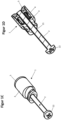
- Figure 1 comprehensively the Figures 1A-1D is a first embodiment of the assembly device according to the invention shown.
- Figure 1A a side view
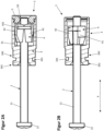
- Figure 1B a longitudinal section, with the threaded rod not shown in section.
- the longitudinal section is also shown in an isometric view in Figure 1D
- Figure 1C a plan view of the embodiment in the assembled state is shown.
- the assembly device consists of a threaded bushing 1 and a threaded rod 2.
- the threaded rod is elongated along a longitudinal direction X and has a rod thread 21 extending around the longitudinal axis of the threaded rod 2 along a longitudinal axis that runs in the longitudinal direction X.
- the threaded rod also has a head element 22, which is designed as a screw head and has recesses that allow the use of a Phillips screwdriver to rotate the threaded rod about the longitudinal axis.
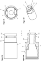
- the threaded bushing comprises a first bushing part 4 and a second bushing part in the form of a fixing part 3.
- the fixing part 3 is designed as a sleeve.
- the threaded bushing has a bushing thread 11 which is designed to correspond to the rod thread 21 and has the same thread pitch as the rod thread 21.
- the first bushing part has two sections 41, 42 which are connected by means of elastic webs 431, 432.
- the elastic webs 431, 432 run with a constant radius around the longitudinal axis L.
- the webs 431, 432 have a significantly smaller extension in the longitudinal direction X than perpendicular to the longitudinal direction X, wherein the webs 431, 432 have a constant cross-section circumferentially around the longitudinal axis.
- the sections 41, 42 both form the bushing thread 11.
- the height of the thread ridges of the bushing thread 11 changes in such a way that the height of the thread ridges in the holding state increases at least in sections towards the head element 22 of the threaded rod 2, which can be generally advantageous.
- the threaded rod 2 is guided through the threaded bushing 1, protruding through a through opening 39 into the fixing part 3 and further through a through opening 59 formed by a closure part 5.
- Figure 1 the assembly device is shown in the assembled state.
- the area of the bushing thread 11 facing away from the screw head 22 in the longitudinal direction X forms the first holding surface 101 of the threaded bushing 1, which is in contact with the corresponding first holding surface 201 of the threaded rod 2.
- the second holding surface 102 of the threaded bushing 1, which is arranged in the longitudinal direction X starting from the first holding surface 101 of the threaded bushing 1 in the direction of the screw head 22 next to the first holding surface 101 and is also formed by the bushing thread 11, is in contact with the rod thread 21.
- the rod thread 21 forms a second holding surface 202 of the threaded rod 2, which can be brought into contact with the second holding surface 102 of the threaded bushing 1 by transferring the assembly device into the holding state.
- at least one of the first retaining surfaces 101, 201 can form an intersection with one of the second retaining surfaces 102, 202 or, in particular, correspond thereto.
- the retaining surfaces correspond to the area of the threads 11, 21 which are in engagement with one another in the respective states. This area can, depending on the intended play of the thread pairing, include areas of the thread lands, in particular their flanks, as well as the thread root.
- the closure part 5 is connected to the fixing part 3 by means of a detachable snap-in connection.
- the snap-in connection is established in that a formed bead, which extends transversely to the longitudinal direction X circumferentially around the longitudinal axis, engages in a corresponding circumferential groove which is formed by the fixing part 3. While the closure part 5 and the fixing part 3 are separated from each other, the first bushing part 4 is removable.
- the through openings 39, 59 are each formed with at least one chamfer, which facilitates insertion of the threaded rod 2 into the respective through opening 39, 59.
- the first bushing part 4 is in an area of its two sections 41, 42 on the in Figure 1A tapered along the longitudinal direction on the side facing left.
- the two sections 41, 42 have, in a tapered region, the taper by means of a conical surface which is located radially outward to the longitudinal axis X and which is arranged at a taper angle with respect to the longitudinal axis.
- the fixing part 3 forms the pressing surfaces distributed around the circumference, which are also formed along the longitudinal direction X in such a way that the fixing part 3 tapers along the longitudinal direction X, the taper extending conically according to a taper angle between the longitudinal axis and the tapered surface.
- Stop surfaces are provided extending transversely to the longitudinal direction X and adjacent to the pressing surfaces, wherein the first bushing part 4, upon reaching the holding state, abuts the stop surfaces with correspondingly formed surfaces, wherein further rotation about the longitudinal axis along the direction of rotation along which the holding state was reached starting from the assembled state is blocked by the stop effect of the stop surfaces.
- the fixing part 3 has, at an end of its extension in the longitudinal direction facing away from the closure part 5, a first
- the second fastening section 342 and the third fastening section 343 are, as in particular from Figure 1C is elliptical with respect to its outer surface perpendicular to the longitudinal direction X. At least one radius of the ellipse exceeds the extension of the first fastening section 341 perpendicular to the longitudinal direction X, wherein the first fastening section 341, taking into account the through opening 39, has a substantially annular cross-section along the longitudinal direction X.
- the threaded bushing 1 can be connected to the wall of the cistern, or to a section connected to the wall, which is provided, for example, by a splash guard plate that is fixed to the wall and covers a maintenance opening provided in the wall, by passing the second fastening section 342 through and inserting the first fastening section 341 through and into the wall or the section connected to the wall, and by rotating the threaded bushing 1 relative to the wall of the cistern by approximately 90° about the longitudinal axis, wherein the second and the third fastening sections 342, 343 each bear against the wall or the section with a surface that extends primarily transversely to the longitudinal direction, the surfaces facing one another, wherein the first fastening section 341 lies in the wall, so that the threaded bushing 1 projects through the wall of the cistern.
- Figure 2 shows in Figure 2A the embodiment of the assembly device according to the invention in an assembled state and in Figure 2B in a hold state.
- Figure 2A shows the threaded rod 2, which is guided through the threaded bushing 1 and is in engagement with the bushing thread 11 with its rod thread 21 at the same height as the longitudinal direction of the elastic webs 431, 432.
- the holding state which is shown in Figure 2B is shown, can be achieved by rotating the threaded rod 2 relative to the fixing part 3 along a path of movement which runs around the longitudinal axis, wherein the first bushing part 4 can be rotated together with the threaded rod 2 relative to the fixing part 3, after the bushing part 4 has previously been displaced by means of the threaded rod 2 along the longitudinal direction X in such a way that its tapered section is in contact with the pressing surfaces 31 of the fixing part 3.
- the first bushing part 4 rests with its tapered region on the pressing surface 31 of the fixing part 3, wherein simultaneously with the rotating movement the sections 41, 42 of the first bushing part 4 move relative to one another, wherein a restoring force proportional to the rotating movement is formed by the elastic webs 431, 432.
- the region of the bushing thread 11 offset from the elastic webs 431, 432 in the longitudinal direction X which region has higher thread webs, engages with the rod thread 21.
- the first bushing part 4 is thus movable relative to the fixing part 3 over a movement distance which, in the present case, comprises a rotational movement over which the sections 41, 42 are moved towards one another perpendicular to the longitudinal direction X when the rotational movement is carried out from the assembled state to the held state, wherein the rotational movement can be absorbed by the threaded rod 2, since in the assembled state there is a sufficient frictional force between the threaded rod 2 and the first bushing part 4.
- the closure part 5 is not shown.
- the threaded webs of the rod thread 21 engage behind the threaded webs of the bushing thread 11 in such a way that a free displacement of the threaded rod 2 relative to the threaded bushing 3 is no longer possible without a thread-typical forced coupling with a rotational movement of the threaded bushing 1 relative to the threaded rod 2 about the longitudinal axis.
- the assembly device can be released from the holding state and brought into the assembly state by a twisting movement in the opposite direction of twisting of the threaded rod 2 and the first bushing part 4 relative to the fixing part 3.
- Figure 3 shows the fixing part of the threaded bushing 1 in various schematic diagrams, including a top view in Figure 3A , a representation of a section along the longitudinal direction in Figure 3B , a representation of a section perpendicular to the longitudinal direction X in Figure 3C and an isometric view in 3D figure .
- the closure part is not shown.
- the component is made in one piece as an injection-molded part.
- the through-opening 39 forms a chamfer, which allows easier insertion of the threaded rod 2 into the threaded bushing 1.
- the fastening sections 341, 342, 343 are arranged in the longitudinal direction X next to the area which receives the first bushing part 4.
- the fixing part has the pressing surfaces 31 on two radially opposite sides, which, as in Figure 3C can be seen, are arranged offset from one another in a transverse direction which is perpendicular to the longitudinal direction X.
- the pressing surface 31 is tapered and tapers towards the longitudinal axis with a taper angle, wherein the The taper angle increases in the direction of rotation, so that the sections 41, 42 are moved toward one another during the rotational movement that the first bushing part 4 performs relative to the fixing part 3 to achieve the holding state starting from the assembled state.
- the threaded bushing 1 forms a step.
- Figure 4 shows an embodiment of the system according to the invention comprising two mounting devices, which are designed according to the exemplary embodiment explained above and which are offset and spaced apart from one another perpendicular to the longitudinal direction X, a concealed unit designed as a cistern, and a cover plate designed as an actuating plate.
- the actuating plate comprises an actuating plate frame 80 and an actuating panel 81.
- the cistern comprises a splash guard plate 90, which is fixed in position to the wall of the cistern as intended.
- the threaded bushings 1 are each connected to the splash guard plate 90 of the cistern in a manner required for the operating state of the system.
- the threaded rods 2 are each guided through a respective passage of the
- Actuating plate frame 80 wherein the head element 22 of the threaded rod 2 with its extension transverse to the longitudinal direction X projects beyond the extension of the passage of the actuating plate frame 80, so that the actuating plate frame 80 can be pressed by the head element 22 against a pre-wall, not shown.
- the threaded rods 2 can each be inserted into the threaded bushing 1 by inserting them along the longitudinal direction X into the respective associated threaded bushing 1 without being twisted until the head elements 22 of the threaded rods 2 are on the actuator plate frame 80 of the Actuator plate. Subsequently, the threaded rods 2 are each rotated relative to the respectively assigned fixing part 3 fixed to the splash guard plate 90, whereby the holding state of the mounting devices is established, wherein by continuing the rotation in the same direction of rotation, due to the interaction of the rod thread and the bushing thread, a pressing force is generated from the head elements 22 onto the actuator plate frame 80 along the longitudinal direction X.
- the actuating panel 81 can be placed onto the actuator plate frame 80 along the longitudinal direction X and can be fixed to the actuator plate by means of snap connections.
Landscapes
- Engineering & Computer Science (AREA)
- General Engineering & Computer Science (AREA)
- Mechanical Engineering (AREA)
- Clamps And Clips (AREA)
- Connection Of Plates (AREA)
Abstract
Die Erfindung betrifft ein Verfahren zur lösbaren Fixierung einer Abdeckplatte relativ zu einer Unterputzeinheit, insbesondere zu einem Spülkasten, mittels zumindest einer Montageeinrichtung, die einen Gewindestab (2) und eine Gewindebuchse (1) umfasst, wobei der Gewindestab (2) in die an der Unterputzeinheit fixierte Gewindebuchse (1) eingeführt wird zur Realisierung eines Montagezustands der Montageeinrichtung, in dem die Gewindebuchse (1) und der Gewindestab (2) zum Hemmen einer Relativbewegung mit zueinander korrespondierenden ersten Halteflächen (101, 201) aneinander anliegen, wobei nach der Realisierung des Montagezustands der Montageeinrichtung zumindest zwei Abschnitte (41, 42) senkrecht zur Längsrichtung (X) zueinander bewegt werden unter Veränderung ihrer Relativposition zueinander zum Verändern der zueinander korrespondierenden Halteflächen (101, 102, 201, 202), mit denen die Gewindebuchse (1) und der Gewindestab (2) aneinander anliegen, wodurch ein Haltezustand der Montageeinrichtung realisiert wird, und in dem eine Verschiebung des Gewindestabs (1) zur Gewindebuchse (1) vermieden ist.The invention relates to a method for the releasable fixing of a cover plate relative to a concealed unit, in particular to a cistern, by means of at least one mounting device comprising a threaded rod (2) and a threaded bushing (1), wherein the threaded rod (2) is inserted into the threaded bushing (1) fixed to the concealed unit to realize an assembled state of the mounting device in which the threaded bushing (1) and the threaded rod (2) bear against one another with mutually corresponding first holding surfaces (101, 201) to inhibit a relative movement, wherein after the realization of the assembled state of the mounting device at least two sections (41, 42) are moved perpendicular to the longitudinal direction (X) with changing their relative position to one another to change the mutually corresponding holding surfaces (101, 102, 201, 202) with which the threaded bushing (1) and the threaded rod (2) bear against one another, whereby a holding state of the mounting device is realized, and in which a displacement of the threaded rod (1) to the threaded bushing (1) is avoided.
Description
Die Erfindung betrifft eine Montageeinrichtung, ein System umfassend die Montageeinrichtung und ein Verfahren zur Verwendung des Systems zur Fixierung einer Abdeckplatte an einer Unterputzeinheit, insbesondere an einer Wandung eines Spülkastens.The invention relates to a mounting device, a system comprising the mounting device and a method for using the system for fixing a cover plate to a concealed unit, in particular to a wall of a cistern.
Gattungsgemäße Montagevorrichtungen werden bei Sanitärinstallationen, insbesondere bei Toiletteninstallationen, verwendet. Die Montageeinrichtungen werden verwendet, um Abdeckplatten, die dazu verwendet werden, um Elemente von Unterputzeinheiten einer Sanitärinstallation, beispielweise Elemente eines Unterputzspülkastens, einer Unterputzthermostateinheit oder einer Unterputzrohranschlussstelle, zu verdecken, relativ zu den Unterputzeinheiten festzulegen. Die Abdeckplatten dienen dabei jedenfalls der Abdeckung, oftmals jedoch auch zur Realisierung weiterer Funktionen. Solche Abdeckplatten sind daher oftmals als Betätigungsplatten ausgebildet, die Betätigungstasten aufweisen, über die die Unterputzeinheit betätigt werden kann. Die Abdeckplatten sind somit üblicherweise so an einer Vorwand montiert, dass sie von einem Raum aus, der durch die Vorwand begrenzt ist, zugänglich sind, und verdecken dabei einen Abschnitt der Unterputzeinheit, die sich hinter der Vorwand befindet. Eine Vorwand ist neben der technisch üblichen Definition insbesondere als Wandelement zu verstehen, welches vor einer weiteren Wand angeordnet und mit dieser verbunden ist unter Ausbildung eines Hohlraums zwischen Vorwand und Wand. Zur Betätigung eines Spülkastens ist meist eine von dem Spülkasten separat beabstandet angeordnete, als Betätigungsplatte ausgebildete Abdeckplatte vorgesehen. Die Betätigungsplatte dient der Betätigung zur Auslösung von Funktionen des Spülkastens. Die Betätigungsplatte weist üblicherweise einen Betätigungsplattenrahmen auf, der relativ zum Spülkasten lösbar fixiert wird, sowie eine Betätigungsblende mit Betätigungstasten, die lösbar an dem Betätigungsplattenrahmen fixiert wird. Die Betätigungstasten werden üblicherweise über Betätigungsstifte oder über eine Elektronik mit einem Ablaufventil verbunden, so dass über sie eine Spülung ausgelöst werden kann. Die Betätigungsplatte ist herkömmlicherweise durch entsprechende Verbindungsmittel am Spülkasten fixiert. Ein gattungsgemäßer Spülkasten weist eine Wandung auf, in der Spülwasser für eine Spülung gesammelt wird. Üblicherweise wird die Betätigungsplatte relativ zur Wandung fixiert, insbesondere mittelbar oder unmittelbar an der Wandung fixiert. Bevorzugt wird sie an einer Spritzschutzplatte fixiert, die an der Wandung lösbar fixiert ist und eine in der Wandung vorgesehene Revisionsöffnung verschließt. Der Abschnitt der Betätigungsplatte, über den die Betätigungsplatte betätigbar ist, insbesondere die Betätigungsplatte, und die Wandung sind üblicherweise im Betriebszustand voneinander beabstandet und durch die entsprechenden Verbindungsmittel relativ zueinander festgelegt. Analog wird sonst bei einer Unterputzeinheit üblicherweise ein Wandabschnitt vorgesehen, beispielsweise durch eine Blech- oder Kunststoffplatte oder ein geeignetes Profil, an dem über herkömmliche Verbindungsmittel die Abdeckplatte fixiert wird. Häufig verdeckt die Abdeckplatte, insbesondere die erläuterte Betätigungsplatte eines Spülkastens, eine Wartungsöffnung in der Vorwand. Zu Wartungszwecken kann die Abdeckplatte gelöst und von der Wartungsöffnung entfernt werden, um insbesondere für Wartungspersonal einen Zugang zu den optisch verdeckten Elementen der Unterputzeinheit, insbesondere des Spülkastens, durch die Wartungsöffnung zu ermöglichen. Zur Durchführung der Wartung wird daher die Fixierung der Abdeckplatte, insbesondere der Betätigungsplatte relativ zur Wandung des Spülkastens, regelmäßig gelöst und nach Abschluss der Wartung wiederhergestellt. Die Verbindungsmittel sind deshalb üblicherweise dergestalt ausgeführt, dass sie eine lösbare Fixierung ermöglichen. Die Verbindungsmittel sind gattungsgemäß als Montageeinrichtung ausgeführt, umfassend einen Gewindestab, der sich mit seiner Längsachse in einer Längsrichtung erstreckt und insbesondere entlang des überwiegenden Teils seiner Längserstreckung ein Gewinde aufweist. Weiterhin umfasst die Montageeinrichtung gattungsgemäß üblicherweise ein an der Unterputzeinheit, insbesondere an der Wandung des Spülkastens fixiertes, korrespondierend zu dem Gewinde des Gewindestabs ausgebildetes Gewinde. Unter der Längserstreckung des Gewindestabs ist dabei die Erstreckung zu verstehen, die entlang einer Längsachse verläuft, entlang derer der Gewindestab sein Gewinde ausbildet, so dass das Gewinde um die Längsachse umläuft. Die Richtung entlang dieser Längsachse ist als Längsrichtung bezeichnet. Zur Fixierung der Betätigungsplatte ist der Gewindestab durch eine dafür vorgesehene Öffnung der Abdeckplatte geführt und in das an dem Spülkasten vorgesehene Gewinde geschraubt, wodurch eine Kraft aufgebaut ist, die die Abdeckplatte an die Vorwand anlegt und relativ zu der Unterputzeinheit, insbesondere zu der Wandung des Spülkastens fixiert. Meist ist zur Fixierung unterstützend zumindest eine weitere Montageeinrichtung in analoger Weise verwendet. Diese mehreren Montageeinrichtungen sind meist in einer Richtung senkrecht zur Längsrichtung voneinander beabstandet, wobei die Montageeinrichtungen bevorzugt jeweils einen Abstand zum Mittelpunkt der Abdeckplatte, bezogen auf dieselbe Richtung, aufweisen. Die Länge des Gewindestabs überschreitet in gattungsgemäßen Montageeinrichtungen regelmäßig eine erforderliche Mindestlänge, die dem Abstand zwischen der Abdeckplatte und der Unterputzeinheit, insbesondere der Betätigungsplatte und der Wandung des Spülkastens entspricht. Denn da der Abstand zwischen einer Raumseite der Vorwand, an der die Abdeckplatte durch die zumindest eine Montageeinrichtung angelegt fixiert werden soll, je nach Raumumgebung variieren kann, ist üblicherweise eine solche Länge des Gewindestabs vorgesehen, mit der auch bei überdurchschnittlich hohem Abstand zwischen Betätigungsplatte und Wandung eine entsprechende Fixierung erfolgen kann. In einigen Fällen überschreitet die Länge des Gewindestabs die erforderliche Mindestlänge um mindestens 50 %, insbesondere mindestens 100 %. Dadurch ist bei der Montage zur Herstellung des Betriebszustandes ein vergleichsweise langwieriges Einschrauben des Gewindestabes in das korrespondierende Gewinde an der Unterputzeinheit, insbesondere des Spülkastens erforderlich.Generic mounting devices are used in sanitary installations, particularly in toilet installations. The mounting devices are used to fix cover plates, which are used to conceal elements of concealed units of a sanitary installation, for example, elements of a concealed cistern, a concealed thermostat unit, or a concealed pipe connection point, relative to the concealed units. The cover plates serve to conceal the elements, but often also to implement additional functions. Such cover plates are therefore often designed as actuator plates that have actuation buttons via which the concealed unit can be operated. The cover plates are thus usually mounted on a false wall in such a way that they are accessible from a space defined by the false wall, thereby concealing a section of the concealed unit located behind the false wall. In addition to the usual technical definition, a pre-wall is to be understood in particular as a wall element which is arranged in front of another wall and is connected to it, forming a hollow space between the pre-wall and the wall. To operate a cistern, a cover plate designed as an actuation plate is usually provided, spaced separately from the cistern. The actuation plate is used to activate the functions of the cistern. The actuation plate usually has an actuation plate frame which is releasably fixed relative to the cistern, as well as an actuation panel with actuation buttons which are releasably fixed to the actuation plate frame. The actuation buttons are usually connected to a drain valve via actuation pins or electronics so that a flush can be triggered via them. The actuation plate is conventionally fixed to the cistern using appropriate connecting means. A generic cistern has a wall in which flush water is collected for a flush. The actuation plate is usually fixed relative to the wall, in particular directly or indirectly fixed to the wall. Preferably, it is attached to a splash guard plate, which is releasably fixed to the wall and closes an inspection opening provided in the wall. The section of the actuator plate via which the actuator plate is actuated, in particular the actuator plate, and the wall are usually spaced apart from each other in the operating state and fixed relative to each other by the corresponding connecting means. Similarly, a flush-mounted unit usually has a wall section, for example, a sheet metal or plastic plate or a suitable profile, to which the cover plate is fixed using conventional connecting means. The cover plate, in particular the described actuating plate of a cistern, covers a maintenance opening in the pre-wall. For maintenance purposes, the cover plate can be loosened and removed from the maintenance opening in order to enable, in particular for maintenance personnel, access to the visually concealed elements of the concealed unit, in particular of the cistern, through the maintenance opening. To carry out maintenance, the fixation of the cover plate, in particular of the actuating plate, relative to the wall of the cistern is therefore regularly loosened and restored after completion of the maintenance. The connecting means are therefore usually designed in such a way that they enable releasable fixation. The connecting means are generically designed as a mounting device comprising a threaded rod which extends with its longitudinal axis in a longitudinal direction and has a thread in particular along the predominant part of its longitudinal extent. Furthermore, the mounting device generically comprises a thread fixed to the concealed unit, in particular to the wall of the cistern, and formed corresponding to the thread of the threaded rod. The longitudinal extension of the threaded rod is understood to be the extension that runs along a longitudinal axis along which the threaded rod forms its thread, so that the thread runs around the longitudinal axis. The direction along this longitudinal axis is referred to as the longitudinal direction. To fix the actuator plate, the threaded rod is guided through a designated opening in the cover plate and screwed into the thread provided on the cistern, whereby a force is built up that applies the cover plate to the pre-wall and fixes it relative to the concealed unit, in particular to the wall of the cistern. Usually, at least one further mounting device is provided to support the fixation. used in an analogous manner. These multiple mounting devices are usually spaced from one another in a direction perpendicular to the longitudinal direction, with the mounting devices preferably each having a distance from the center of the cover plate, relative to the same direction. The length of the threaded rod in generic mounting devices regularly exceeds a required minimum length, which corresponds to the distance between the cover plate and the concealed unit, in particular the actuator plate and the wall of the cistern. Because the distance between one side of the wall, to which the cover plate is to be fixed by the at least one mounting device, can vary depending on the room environment, a length of the threaded rod is usually provided that allows appropriate fixing even with an above-average distance between the actuator plate and the wall. In some cases, the length of the threaded rod exceeds the required minimum length by at least 50%, in particular at least 100%. As a result, during assembly, in order to establish the operating state, a comparatively time-consuming process of screwing the threaded rod into the corresponding thread on the concealed unit, in particular the cistern, is necessary.
Aufgabe der Erfindung ist, eine Montageeinrichtung und ein Verfahren zur Fixierung einer Abdeckplatte an einer Unterputzeinheit bereitzustellen, die zumindest einige der Nachteile gattungsgemäßer Montageeinrichtungen zumindest teilweise behebt.The object of the invention is to provide a mounting device and a method for fixing a cover plate to a flush-mounted unit, which at least partially eliminates at least some of the disadvantages of generic mounting devices.
Als eine erfindungsgemäße Lösung wird ein Verfahren zur lösbaren Fixierung einer Abdeckplatte relativ zu einer Unterputzeinheit, insbesondere zu einem Spülkasten, mittels zumindest einer Montageeinrichtung vorgeschlagen. Die Montageeinrichtung umfasst einen sich mit seiner Längsachse in einer Längsrichtung erstreckenden Gewindestab und eine Gewindebuchse. Der Gewindestab wird in die an der Unterputzeinheit fixierte Gewindebuchse eingeführt zur Realisierung eines Montagezustands der Montageeinrichtung, in dem der Gewindestab innerhalb einer Längserstreckung von der Gewindebuchse aufgenommen ist und in dem die Gewindebuchse und der Gewindestab zum Hemmen einer Relativbewegung entlang der Längsrichtung mit zueinander korrespondierenden ersten Halteflächen aneinander anliegen und in dem der Gewindestab bei Aufbringung einer zwischen Gewindestab und Gewindebuchse in der Längsrichtung wirkenden externen Verschiebekraft entlang der Längsrichtung relativ zu der Gewindebuchse verschiebbar ist. Nach der Realisierung des Montagezustands der Montageeinrichtung werden zumindest zwei Abschnitte der Gewindebuchse, die sich über einen selben Längsabschnitt der Gewindebuchse innerhalb der Längserstreckung erstrecken, mittels einer Bewegung, insbesondere Drehung, des Gewindestabs senkrecht zur Längsrichtung zueinander bewegt unter Veränderung ihrer Relativposition zueinander zum Verändern der zueinander korrespondierenden Halteflächen, mit denen die Gewindebuchse und der Gewindestab aneinander anliegen, wodurch ein Haltezustand der Montageeinrichtung realisiert wird, in dem die Gewindebuchse und der Gewindestab mit zueinander korrespondierenden zweiten Halteflächen aneinander anliegen, die sich von den ersten Halteflächen unterscheiden, und in dem durch ein Ineinandergreifen von einem um die Längsachse des Gewindestabs umlaufenden Stabgewinde und einem mit dem Stabgewinde korrespondierenden Buchsengewinde der Gewindebuchse bei Aufbringung der zwischen Gewindestab und Gewindebuchse in der Längsrichtung wirkenden externen Verschiebekraft eine Verschiebung des Gewindestabs zur Gewindebuchse vermieden ist. Bevorzugt weist der Gewindestab eine Längserstreckungslänge auf, die mindestens das Doppelte, insbesondere mindestens das Vierfache, insbesondere mindestens das Zehnfache, der Längserstreckung beträgt. Bevorzugt ist das Stabgewinde über mindestens 50 %, insbesondere mindestens 70 % der Längserstreckungslänge des Gewindestabs ausgebildet.As a solution according to the invention, a method for releasably fixing a cover plate relative to a concealed unit, in particular to a cistern, by means of at least one mounting device is proposed. The mounting device comprises a threaded rod extending with its longitudinal axis in a longitudinal direction and a threaded bushing. The threaded rod is inserted into the threaded bushing fixed to the flush-mounted unit to realize an assembled state of the mounting device in which the threaded rod is received within a longitudinal extent by the threaded bushing and in which the threaded bushing and the threaded rod abut one another with mutually corresponding first holding surfaces to inhibit relative movement along the longitudinal direction and in which the threaded rod is displaceable along the longitudinal direction relative to the threaded bushing upon application of an external displacement force acting between the threaded rod and the threaded bushing in the longitudinal direction. After the assembly state of the assembly device has been realized, at least two sections of the threaded bushing, which extend over a same longitudinal section of the threaded bushing within the longitudinal extent, are moved towards each other by means of a movement, in particular rotation, of the threaded rod perpendicular to the longitudinal direction, thereby changing their relative position to each other in order to change the mutually corresponding holding surfaces with which the threaded bushing and the threaded rod abut each other, whereby a holding state of the assembly device is realized in which the threaded bushing and the threaded rod abut each other with mutually corresponding second holding surfaces, which are different from the first holding surfaces, and in which by an engagement of a rod thread running around the longitudinal axis of the threaded rod and a bushing thread of the threaded bushing corresponding to the rod thread, upon application of the external displacement force acting between the threaded rod and the threaded bushing in the longitudinal direction, a displacement of the threaded rod to Threaded bushing is avoided. The threaded rod preferably has a longitudinal extension length that is at least twice, in particular at least four times, in particular at least ten times, the longitudinal extension. The rod thread is preferably formed over at least 50%, in particular at least 70%, of the longitudinal extension length of the threaded rod.
In einer Ausführungsform wird nach der Realisierung des Haltezustands der Gewindestab der Montageeinrichtung um seine Längsachse gedreht, während das Stabgewinde und das Buchsengewinde ineinandergreifen, wobei insbesondere hierdurch eine Fixierkraft erzeugt wird, die zwischen der Abdeckplatte und der Unterputzeinheit wirkt, wobei insbesondere hierdurch die Abdeckplatte an einer Vorwand fixiert wird, hinter der sich die Unterputzeinheit, insbesondere der Spülkasten, insbesondere die Wandung des Spülkastens, befindet.In one embodiment, after the holding state has been achieved, the threaded rod of the mounting device is rotated about its longitudinal axis, while the rod thread and the socket thread engage with each other, in particular thereby generating a fixing force which acts between the cover plate and the concealed unit, in particular thereby fixing the cover plate to a pre-wall behind which the concealed unit, in particular the cistern, in particular the wall of the cistern, is located.
In einer Ausführungsform weist der Gewindestab ein Kopfelement auf, wobei im Montagezustand der Gewindestab so weit in die Gewindebuchse, insbesondere durch ein rotationsfreies Verschieben von Gewindestab und Gewindebuchse zueinander, eingeführt wird, bis das Kopfelement an der Abdeckung anliegt, wobei anschließend der Haltezustand realisiert wird und der Gewindestab durch Rotation um seine Längsachse in Längsrichtung zu der Gewindebuchse bewegt wird, indem Stabgewinde und Buchsengewinde ineinandergreifen. Bevorzugt erfolgt die Rotation um mehr als 270°, insbesondere um mehr als 360°, insbesondere um ein Vielfaches von 360°. Bevorzugt wird durch die Rotation des Gewindestabs eine sich im Verlauf der Rotation erhöhende Presskraft auf die Abdeckplatte aufgebracht, mit der sie gegen eine Vorwand gepresst wird.In one embodiment, the threaded rod has a head element, wherein in the assembled state the threaded rod is inserted into the threaded bushing, in particular by a rotation-free displacement of the threaded rod and threaded bushing relative to one another, until the head element rests against the cover, wherein the holding state is then realized and the threaded rod is moved by rotation about its longitudinal axis in the longitudinal direction towards the threaded bushing, in that the rod thread and bushing thread engage with one another. Preferably, the rotation takes place by more than 270°, in particular by more than 360°, in particular by a multiple of 360°. Preferably, the rotation of the threaded rod applies a pressing force to the cover plate which increases during the course of the rotation and with which it is pressed against a prefabricated wall.
In einer Ausführungsform ist die Abdeckplatte als Betätigungsplatte ausgebildet, die Betätigungstasten aufweist, über die die Unterputzeinheit betätigbar ist, wobei die Abdeckplatte mittels der Montageeinrichtung so an einer Vorwand lösbar montiert wird, dass sie von einem Raum aus, der durch die Vorwand begrenzt ist, zugänglich ist, und dabei einen Abschnitt der Unterputzeinheit, die sich hinter der Vorwand befindet, verdeckt, wobei die Abdeckplatte eine in der Vorwand vorgesehene Wartungsöffnung verdeckt. Nach Lösen der Abdeckplatte von der Vorwand ist die Unterputzeinheit bevorzugt durch die Wartungsöffnung zugänglich. In einer Ausführungsform wird die Montageeinrichtung reversibel von dem Montagezustand in den Haltezustand und von dem Haltezustand in den Montagezustand zurück gebracht. In einer Ausführungsform wird die Abdeckplatte mittels der Montageeinrichtung lösbar an der Vorwand fixiert und anschließend zu Wartungszwecken mittels der Montageeinrichtung von der Vorwand gelöst unter Freigabe der Wartungsöffnung. In einer Ausführungsform ist eine elastische Verbindung zwischen den Abschnitten vorgesehen, die der zum Realisieren des Haltezustands ausgehend von dem Montagezustand durchgeführten Bewegung der Abschnitte zueinander senkrecht zur Längsrichtung entgegenwirkt, wobei die Verbindung insbesondere durch zumindest einen elastischen Steg ausgebildet ist, der senkrecht zur Längsrichtung verläuft. Bevorzugt wird durch die Bewegung der Abschnitte zueinander eine Rückstellkraft ausgebildet, die bei Aufhebung sämtlicher auf die Abschnitte wirkender Kräfte eine Rückkehr in den Montagezustand bewirkt. In einer Ausführungsform werden die Abschnitte zur Realisierung des Haltezustands ausgehend von dem Montagezustand derart zueinander bewegt, dass sie um eine Kippachse, welche im Wesentlichen senkrecht zur Längsrichtung verläuft, relativ zu einander verkippt werden, wodurch ein Winkel zwischen den Abschnitten um die Kippachse verändert wird. In einer Ausführungsform sind die Abschnitte der Gewindebuchse durch einen ersten Buchsenteil ausgebildet, wobei die Gewindebuchse einen als Fixierteil ausgebildeten zweiten Buchsenteil aufweist, wobei unter Realisierung der Bewegung der Abschnitte zueinander ausgehend von dem Montagezustand zum Erreichen des Haltezustands der erste Buchsenteil relativ zu dem Fixierteil innerhalb eines Längserstreckungsbereichs über eine Bewegungsstrecke hinweg bewegt wird.In one embodiment, the cover plate is designed as an actuating plate which has actuating buttons via which the flush-mounted unit can be actuated, wherein the cover plate is detachably mounted to a pre-wall by means of the mounting device such that it is accessible from a space delimited by the pre-wall, and in doing so conceals a section of the flush-mounted unit which is located behind the pre-wall, wherein the cover plate conceals a maintenance opening provided in the pre-wall. After the cover plate has been detached from the pre-wall, the flush-mounted unit is preferably accessible through the maintenance opening. In one embodiment, the mounting device is reversibly brought from the mounted state to the held state and back from the held state to the mounted state. In one embodiment, the cover plate is detachably fixed to the pre-wall by means of the mounting device and then detached from the pre-wall for maintenance purposes by means of the mounting device, thereby exposing the maintenance opening. In one embodiment, an elastic connection is provided between the sections, which counteracts the movement of the sections relative to one another perpendicular to the longitudinal direction, carried out to realize the holding state starting from the assembled state, wherein the connection is formed in particular by at least one elastic web which runs perpendicular to the longitudinal direction. Preferably, the movement of the sections relative to one another creates a restoring force which, when all forces acting on the sections are removed, causes a return to the assembled state. In one embodiment, to realize the holding state, the sections are moved relative to one another starting from the assembled state in such a way that they are tilted relative to one another about a tilt axis which runs substantially perpendicular to the longitudinal direction, whereby an angle between the sections about the tilt axis. In one embodiment, the sections of the threaded bushing are formed by a first bushing part, wherein the threaded bushing has a second bushing part designed as a fixing part, wherein, while realizing the movement of the sections relative to one another, starting from the assembled state to achieve the holding state, the first bushing part is moved relative to the fixing part over a movement distance within a longitudinal extension range.
In einer Ausführungsform liegt der erste Buchsenteil im Haltezustand an zumindest einer von dem Fixierteil ausgebildeten Anschlagfläche an, wobei die Anschlagfläche die Beweglichkeit des ersten Buchsenteils relativ zum Fixierteil und die Veränderung der Relativposition der Abschnitte des ersten Buchsenteils begrenzt. In einer Ausführungsform ist der erste Buchsenteil in dem Montagezustand von der Anschlagfläche beabstandet und wird ausgehend von dem Montagezustand durch eine, insbesondere kontinuierliche, Verschiebebewegung relativ zum Fixierteil in Anlage mit der Anschlagfläche des Fixierteils gebracht. In einer Ausführungsform umfasst die Verschiebebewegung eine Drehbewegung um eine entlang der Längsrichtung verlaufende Drehachse, wobei der Buchsenteil und der Fixierteil dergestalt zueinander korrespondierend ausgebildet sind, dass ausgehend von dem Montagezustand der Haltezustand durch Ausführen der Drehbewegung um einen definierten Drehwinkel erreicht wird, welcher insbesondere weniger als 270°, bevorzugt weniger als 180° beträgt. In einer Ausführungsform wird ausgehend von dem Montagezustand der Haltezustand durch ein Verdrehen des Gewindestabs relativ zu dem Fixierteil realisiert. In einer Ausführungsform wird die Montageeinrichtung nach Realisierung des Haltezustands von dem Haltezustand in den Montagezustand überführt, indem der erste Buchsenteil durch Aufbringen einer Lösekraft relativ zum Fixierteil bewegt wird, wobei die Lösekraft durch eine Drehbewegung des Gewindestabs auf den ersten Buchsenteil relativ zu dem Fixierteil aufgebracht wird.In one embodiment, the first bushing part, in the held state, rests against at least one stop surface formed by the fixing part, wherein the stop surface limits the mobility of the first bushing part relative to the fixing part and the change in the relative position of the sections of the first bushing part. In one embodiment, the first bushing part is spaced from the stop surface in the assembled state and, starting from the assembled state, is brought into contact with the stop surface of the fixing part by a, in particular continuous, displacement movement relative to the fixing part. In one embodiment, the displacement movement comprises a rotational movement about an axis of rotation running along the longitudinal direction, wherein the bushing part and the fixing part are configured to correspond to one another in such a way that, starting from the assembled state, the holding state is achieved by executing the rotational movement through a defined angle of rotation, which is in particular less than 270°, preferably less than 180°. In one embodiment, starting from the assembled state, the holding state is realized by rotating the threaded rod relative to the fixing part. In one embodiment, the assembly device is, after realization of the holding state of the holding state into the assembly state by moving the first socket part relative to the fixing part by applying a release force, wherein the release force is applied to the first socket part relative to the fixing part by a rotational movement of the threaded rod.
In einer Ausführungsform ist die Abdeckung als Betätigungsplatte ausgebildet und weist einen Betätigungsplattenrahmen und eine Betätigungsblende auf, wobei der Gewindestab vor Realisierung des Montagezustands der Montageeinrichtung durch eine Durchführung des Betätigungsplattenrahmens durchgeführt wird und anschließend unter Realisierung des Montagezustands in die Gewindebuchse eingeführt wird. Bevorzugt weist der Betätigungsrahmen zumindest zwei Durchführungen auf, wobei durch jede der Durchführungen jeweils ein ihr zugeordneter Gewindestab durchgeführt wird und anschließend in eine ihm jeweils zugeordnete Gewindebuchse eingeführt wird. Jeweils einer der Gewindestäbe und die ihm zugeordnete Gewindebuchse sind Teil von jeweils einer Montageeinrichtung. Insbesondere bilden jeweils ein Gewindestab und die ihm zugeordnete Gewindebuchse jeweils eine Montageeinrichtung aus.In one embodiment, the cover is designed as an actuating plate and has an actuating plate frame and an actuating panel, wherein the threaded rod is passed through a passage of the actuating plate frame before the assembly state of the assembly device is realized and is then inserted into the threaded bushing upon realization of the assembly state. Preferably, the actuating frame has at least two passages, wherein a threaded rod assigned to it is passed through each of the passages and is then inserted into a threaded bushing assigned to it. Each of the threaded rods and the threaded bushing assigned to it are part of a respective assembly device. In particular, each threaded rod and the threaded bushing assigned to it each form a respective assembly device.
Als eine weitere erfindungsgemäße Lösung wird eine Montageeinrichtung zur lösbaren Fixierung einer Abdeckplatte relativ zu einer Unterputzeinheit, insbesondere zu dem Spülkasten, insbesondere der Wandung des Spülkastens vorgeschlagen, die einen Gewindestab aufweist und eine Gewindebuchse aufweist. Der Gewindestab erstreckt sich mit seiner Längsachse in einer Längsrichtung. Der Gewindestab ist in einem Montagezustand innerhalb einer Längserstreckung von der Gewindebuchse aufgenommen. Die Längserstreckung ist innerhalb eines Abschnitts der Längserstreckung des Gewindestabes ausgebildet. Die Längserstreckung kann durchgehend ausgebildet sein. Die Längserstreckung ist bevorzugt kleiner als die Hälfte, insbesondere kleiner als ein Viertel der Längserstreckungslänge des Gewindestabs, beträgt insbesondere zwischen einem Zehntel und einem Halben der Längserstreckungslänge des Gewindestabs. Gewindestab und Gewindebuchse können im Montagezustand und im Haltezustand ineinander angeordnet sein. Gewindestab und Gewindebuchse können selbstverständlich auch in einem weiteren Zustand der Montageeinrichtung, der keinem der genannten Zustände entspricht, ebenfalls ineinander angeordnet sein, wobei ein bestimmter Zustand eine bestimmte Anordnung der Bestandteile der Montageeinrichtung zueinander bezeichnet.As a further solution according to the invention, a mounting device for releasably fixing a cover plate relative to a concealed unit, in particular to the cistern, in particular the wall of the cistern, is proposed, which mounting device has a threaded rod and a threaded bushing. The threaded rod extends with its longitudinal axis in a longitudinal direction. In an assembled state, the threaded rod is received within a longitudinal extent by the threaded bushing. The longitudinal extent is formed within a section of the longitudinal extent of the threaded rod. The longitudinal extent can be continuous. The longitudinal extent is preferably less than half, in particular less than a quarter of the longitudinal extent of the threaded rod, and is in particular between a tenth and a half of the longitudinal extent of the threaded rod. The threaded rod and threaded bushing can be arranged one inside the other in the assembled state and in the held state. The threaded rod and threaded bushing can of course also be arranged one inside the other in a further state of the assembly device that does not correspond to any of the aforementioned states, wherein a specific state designates a specific arrangement of the components of the assembly device relative to one another.
Der Gewindestab weist ein Stabgewinde auf, das um die Längsachse des Gewindestabes verläuft. Die Längsachse des Gewindestabes entspricht somit der Drehachse, um die der Gewindestab drehbar ist, um das Stabgewinde in ein korrespondierendes Gewinde zu schrauben und/oder aus einer Schraubverbindung mit dem korrespondierenden Gewinde zu lösen. Der Gewindestab kann als Schraube ausgebildet sein. Der Gewindestab kann ein Kopfelement, insbesondere einen Schraubenkopf aufweisen, das radial, d. h. senkrecht zur Längsrichtung, über das Stabgewinde vorsteht und insbesondere an einem Längsende des Gewindestabs ausgebildet ist. Der Schraubenkopf ist auf übliche Weise gestaltet, beispielsweise an Inbus-, Kreuzschlitz-, Sechskant oder Torx-Schraubenkopf, so dass über ein Werkzeug auf einfache Weise ein Verdrehen des Gewindestabs ermöglicht ist. Insbesondere kann das Kopfelement zu Anlage an der Abdeckplatte vorgesehen sein und eine Fläche zur Anlage an der Abdeckplatte aufweisen. Die Gewindebuchse weist ein Buchsengewinde auf. Buchsengewinde und Stabgewinde sind jeweils zumindest abschnittsweise zueinander korrespondierend ausgebildet. Das Stabgewinde kann über mindestens 50 %, insbesondere mindestens 70 % der Längserstreckungslänge des Gewindestabs hinweg ausgebildet sein, insbesondere durchgehend umlaufend ausgebildet sein oder in Umfangsabschnitten umlaufend ausgebildet sein. Das Stabgewinde kann Unterbrechungen in Längsrichtung entlang der Längsachse aufweisen oder in Längsrichtung durchgehend ausgebildet sein. Das Buchsengewinde kann durchgehend oder in Umfangsabschnitten umlaufend ausgebildet sein. Das Buchsengewinde kann in Längsrichtung unterbrochen oder durchgehend ausgebildet sein. Das Buchsengewinde und das Stabgewinde können in dem Montagezustand und in dem Haltezustand ineinandergreifen, wobei sie insbesondere einander im Haltezustand und im Montagezustand unterschiedlich tief hintergreifen. Das Buchsengewinde kann erst durch einen Eingriff mit dem korrespondieren Stabgewinde ausbildbar sein, insbesondere indem die Gewindebuchse einen verformbaren, insbesondere elastisch verformbaren Abschnitt aufweist, in den das Stabgewinde einschraubbar ist unter Ausbildung des Buchsengewindes. In dem Fall liegen im Haltezustand Stab- und Buchsengewinde vor und insbesondere auch im Montagezustand, wobei bevorzugt der Gewindestab für sich genommen und insbesondere die Gewindebuchse für sich genommen, d. h. als Bauteileigenschaft ohne zwingenden Zusammenhang zu einem anderen Bauteil, ein entsprechendes Gewinde aufweist. Das Stabgewinde bzw. Buchsengewinde kann erst durch den Eingriff mit dem korrespondieren Buchsengewinde bzw. Stabgewinde ausbildbar sein.The threaded rod has a rod thread that runs around the longitudinal axis of the threaded rod. The longitudinal axis of the threaded rod thus corresponds to the axis of rotation about which the threaded rod can be rotated in order to screw the rod thread into a corresponding thread and/or to release it from a screw connection with the corresponding thread. The threaded rod can be designed as a screw. The threaded rod can have a head element, in particular a screw head, that projects radially, i.e. perpendicular to the longitudinal direction, beyond the rod thread and is formed in particular at a longitudinal end of the threaded rod. The screw head is designed in the usual way, for example with an Allen, Phillips, hexagon, or Torx screw head, so that the threaded rod can be easily rotated using a tool. In particular, the head element can be provided for contact with the cover plate and have a surface for contact with the cover plate. The threaded bushing has a bushing thread. The bushing thread and the rod thread are each designed to correspond to one another, at least in sections. The rod thread can have at least 50%, in particular at least 70% of the longitudinal extension length of the threaded rod, in particular be designed to be continuously circumferential or to be circumferential in circumferential sections. The rod thread can have interruptions in the longitudinal direction along the longitudinal axis or be designed to be continuous in the longitudinal direction. The socket thread can be designed to be continuous or to be circumferential in circumferential sections. The socket thread can be designed to be interrupted or continuous in the longitudinal direction. The socket thread and the rod thread can engage with each other in the assembled state and in the held state, wherein they engage behind each other in particular to different depths in the held state and in the assembled state. The socket thread can only be formed by engagement with the corresponding rod thread, in particular in that the threaded socket has a deformable, in particular elastically deformable section, into which the rod thread can be screwed to form the socket thread. In this case, rod and bushing threads are present in the holding state and, in particular, also in the assembled state, whereby preferably the threaded rod in isolation and, in particular, the threaded bushing in isolation, i.e., as a component property without a mandatory connection to another component, has a corresponding thread. The rod thread or bushing thread can only be formed through engagement with the corresponding bushing thread or rod thread.
Bei Aufbringung einer externen Verschiebekraft sind Gewindestab und Gewindebuchse im Montagezustand bevorzugt zerstörungsfrei und reversibel relativ zueinander entlang der Längsrichtung verschiebbar. Die Verschiebekraft wirkt zwischen Gewindestab und Gewindebuchse und weist einen vorbestimmten Betrag auf.When an external displacement force is applied, the threaded rod and threaded bushing can be displaced relative to each other in the longitudinal direction in a preferably non-destructive and reversible manner in the assembled state. The displacement force acts between the threaded rod and the threaded bushing and has a predetermined amount.
In dem Haltezustand sind Gewindestab und Gewindebuchse bei Aufbringung der externen Verschiebekraft relativ zueinander entlang der Längsrichtung nicht verschiebbar. In dem Haltezustand ist eine Verschiebung von Gewindestab und Gewindebuchse relativ zueinander somit vermieden, wenn im Haltezustand eine genau solche externe Verschiebekraft aufgebracht wird, deren Aufbringung im Montagezustand eine Verschiebung bewirkt. Als Verschiebung ist allgemein eine insbesondere translatorische Bewegung zweier Körper relativ zueinander gemeint, welche von weiteren Bewegungen entkoppelt ausführbar ist. Insbesondere ist als Verschiebung eine Bewegung zweier Körper relativ zueinander gemeint, welche keine Zwangskopplung mit einer weiteren Bewegung aufweist. In dem Haltezustand ist eine solche Zwangskopplung vorhanden und umfasst insbesondere die Zwangskopplung einer Rotation und einer Translation. Die Gewindebuchse und der Gewindestab liegen in dem Montagezustand und in dem Haltezustand zum Hemmen einer Relativbewegung entlang der Längsrichtung, insbesondere innerhalb der Längserstreckung, mit zueinander korrespondierenden Halteflächen aneinander an. Im Montagezustand und im Haltezustand ist eine Krafteinwirkung entlang Längsrichtung gehemmt.In the held state, the threaded rod and threaded bushing cannot be displaced relative to one another along the longitudinal direction when the external displacement force is applied. In the held state, displacement of the threaded rod and threaded bushing relative to one another is thus avoided if, in the held state, exactly the same external displacement force is applied as would cause displacement in the assembled state. Displacement generally refers to a movement, in particular a translational movement, of two bodies relative to one another that can be carried out decoupled from other movements. In particular, displacement refers to a movement of two bodies relative to one another that does not have a forced coupling with any other movement. In the held state, such a forced coupling is present and includes, in particular, the forced coupling of a rotation and a translation. In the assembled state and in the held state, the threaded bushing and the threaded rod bear against one another with corresponding holding surfaces to inhibit relative movement along the longitudinal direction, in particular within the longitudinal extent. In the assembled state and in the held state, the action of a force along the longitudinal direction is inhibited.
Gewindestab und Gewindebuchse sind erfindungsgemäß derart zueinander korrespondierend ausgebildet, dass der in Längsrichtung wirkenden externen Verschiebekraft im Montagezustand eine erste Haltekraft entgegengerichtet wirkt, wobei, wenn die externe Verschiebekraft bezüglich ihres Betrages den Betrag einer ersten Haltekraft nicht überschreitet, die Verschiebung von Gewindestab und Gewindebuchse entlang der Längsrichtung relativ zueinander vermieden ist, und bei Aufbringung der externen Verschiebekraft, wenn die externe Verschiebekraft bezüglich ihres Betrages den Betrag der ersten Haltekraft überschreitet, Gewindestab und Gewindebuchse entlang der Längsrichtung relativ zueinander verschiebbar sind, wobei in einem Haltezustand durch ein Ineinandergreifen von einem um die Längsachse des Gewindestabs umlaufenden Stabgewinde und einem mit dem Stabgewinde korrespondierenden Buchsengewinde eine zweite Haltekraft gegeben ist, die größer ist als die erste Haltekraft, sodass bei Aufbringung der externen Verschiebekraft eine Verschiebung des Gewindestabs zur Gewindebuchse vermieden ist und erst bei Aufbringung einer die zweite Haltekraft überschreitenden Verschiebekraft eine solche Verschiebung ermöglicht ist. In einer Ausführungsform führt das Aufbringen einer solchen, die zweite Haltekraft überschreitenden Verschiebekraft zwingend zu einer Beschädigung der Montageeinrichtung. Die erste Haltekraft kann weniger als 50 %, insbesondere weniger als 30 %, insbesondere weniger als 20 % der zweiten Haltekraft betragen. Die Verschiebekraft wird extern aufgebracht, womit ausgeschlossen ist, dass die Verschiebekraft lediglich durch Kräfte der statischen Wirkverbindung der Abschnitte und/oder Komponenten und/oder Elemente der Montageeinrichtung gebildet ist. Die Kräfte der statischen Wirkverbindung können Schnittkräfte sein und/oder durch Eigenspannungen hervorgerufen sein. Die externe Verschiebekraft ist insbesondere durch eine Körperkraft eines Menschen aufbringbar. Insbesondere ist die externe Verschiebekraft durch Hilfsvorrichtungen aufbringbar.According to the invention, the threaded rod and the threaded bushing are designed to correspond to one another in such a way that a first holding force acts in the assembled state in the opposite direction to the external displacement force acting in the longitudinal direction, wherein, if the external displacement force does not exceed the amount of a first holding force, the displacement of the threaded rod and the threaded bushing along the longitudinal direction relative to one another is avoided, and when the external Displacement force: if the external displacement force exceeds the magnitude of the first holding force, the threaded rod and threaded bushing are displaceable relative to one another along the longitudinal direction, wherein in a held state, a second holding force is provided by an interlocking of a rod thread running around the longitudinal axis of the threaded rod and a bushing thread corresponding to the rod thread, which second holding force is greater than the first holding force, so that when the external displacement force is applied, a displacement of the threaded rod relative to the threaded bushing is avoided and such a displacement is only possible when a displacement force exceeding the second holding force is applied. In one embodiment, the application of such a displacement force exceeding the second holding force inevitably leads to damage to the mounting device. The first holding force can be less than 50%, in particular less than 30%, in particular less than 20% of the second holding force. The displacement force is applied externally, which excludes the possibility that the displacement force is formed solely by forces of the static operative connection of the sections and/or components and/or elements of the mounting device. The forces of the static active connection can be shear forces and/or caused by residual stresses. The external displacement force can be applied, in particular, by a human's physical force. In particular, the external displacement force can be applied by auxiliary devices.
In dem Montagezustand und im Haltezustand liegen Gewindebuchse und Gewindestab mit den zueinander korrespondierenden Halteflächen aneinander an. Im Montagezustand liegen Gewindebuchse und Gewindestab dabei mit ersten zueinander korrespondierend ausgebildeten Halteflächen aneinander an. Der Gewindestab weist eine erste Haltefläche des Gewindestabs auf und die Gewindebuchse weist eine erste Haltefläche der Gewindebuchse auf, wobei beide ersten Halteflächen zueinander korrespondieren und aneinander anliegen. Bevorzugt weist zumindest eine der ersten Halteflächen zumindest einen Abschnitt des Buchsengewindes oder des Stabgewindes auf, wobei diese erste Haltefläche insbesondere mit Gewindestegen des Buchsengewindes oder des Stabgewindes an der anderen ersten Haltefläche anliegt. Besonders bevorzugt weist die von dem Gewindestab ausgebildete erste Haltefläche einen Abschnitt des Gewindestabs auf und die von der Gewindebuchse ausgebildete erste Halteflächen einen Abschnitt des Buchsengewindes auf, wobei in dem Montagezustand innerhalb dieses Abschnitts die Gewinde mit ihren Gewindestegen aneinander anliegen. Im Haltezustand liegen Gewindebuchse und Gewindestab mit zweiten zueinander korrespondierend ausgebildeten Halteflächen an. Das Paar an korrespondierenden ersten Halteflächen im Montagezustand unterscheidet sich von dem Paar an korrespondierenden zweiten Halteflächen im Haltezustand, indem sich zumindest eine der ersten Halteflächen von einer der zweiten Halteflächen unterscheidet. Bevorzugt unterscheiden sich sämtliche erste Halteflächen von sämtlichen zweiten Halteflächen, wobei vorgesehen sein kann, dass eine der ersten Halteflächen einen Teil einer der zweiten Halteflächen ausbildet. Ausgehend von dem Montagezustand ist der Haltezustand dadurch herstellbar, dass der Gewindestab und die Gewindebuchse von der Anlage der ersten Halteflächen zueinander zu der Anlage der zweiten Halteflächen zueinander bringbar sind. Die Gewindebuchse weist zumindest zwei, insbesondere genau zwei, Abschnitte auf, die sich über einen selben Längsabschnitt der Gewindebuchse erstrecken. Der Längsabschnitt ist ein Abschnitt der Gewindebuchse, der im Montagezustand oder Haltezustand einem Abschnitt der Erstreckung der Gewindebuchse in Längsrichtung entspricht. Die zumindest zwei Abschnitte können sich vollständig über denselben Längsabschnitt erstrecken. Bevorzugt ist das Buchsengewinde und/oder ist die zweite Haltefläche und/oder die erste Haltefläche der Gewindebuchse durch die Abschnitte ausgebildet, wobei zumindest einer der Abschnitte, insbesondere die Abschnitte, das Buchsengewinde ausbildet bzw. ausbilden. Insbesondere erstrecken sich die Abschnitte im Montagezustand und/oder Haltezustand parallel zu der Längserstreckung des Gewindestabes. Vorzugsweise sind die zumindest zwei Abschnitte im Montagezustand und/oder Haltezustand senkrecht zur Längsrichtung voneinander beabstandet, insbesondere einander gegenüberliegend, angeordnet und von der Längsachse des Gewindestabs beabstandet sowie insbesondere zu der Längsachse exzentrisch angeordnet. Bevorzugt sind sie im Montagezustand und/oder Haltezustand umfänglich um den Gewindestab verteilt. Bevorzugt bilden die zumindest zwei Abschnitte die zweite Haltefläche der Gewindebuchse sowie besonders bevorzugt die erste Haltefläche der Gewindebuchse aus. Die zumindest zwei Abschnitte sind zudem entlang einer Senkrechten zur Längsrichtung relativ zueinander beweglich. Zum Verändern der zueinander korrespondierenden Halteflächen, mit denen Gewindestab und Gewindebuchse aneinander anliegen, sind die zumindest zwei Abschnitte zueinander bewegbar. Insbesondere können die zwei Abschnitte gegenüber ihrer Relativposition im Montagezustand im Haltezustand einen geringeren Abstand zueinander senkrecht zur Längsachse aufweisen. Die Bewegung der Abschnitte zwischen Montagezustand und Haltezustand erfolgt bevorzugt durchgehend. Insbesondere vergrößert sich gegenüber dem Montagezustand ein Eingriffsvolumen, mit welchem der Gewindestab und die Gewindebuchse im Haltezustand ineinandergreifen. Bevorzugt erhöht sich gegenüber dem Montagezustand im Haltezustand der Anteil der Haltefläche des einen Bauteils (Gewindebuchse oder Gewindestab), die senkrecht zu Längsrichtung an der korrespondierenden Haltefläche des anderen Bauteils (Gewindestab oder Gewindebuchse) anliegt. Bevorzugt ist das Buchsengewinde in Form eines Innengewindes ausgebildet. Vorteilhafterweise weist insbesondere in einem solchen Falle der Gewindestab das Stabgewinde in Form eines Außengewindes auf. Der Gewindestab kann aus Metall hergestellt sein. Der Gewindestab und/oder die Gewindebuchse kann aus Kunststoff, insbesondere aus thermoplastischem Kunststoff hergestellt sein. Die Gewindebuchse kann mehrteilig ausgeführt sein. Die Gewindebuchse umfasst vorzugsweise weniger als zehn, besonders bevorzugt weniger als fünf Teile. Als Teile werden in diesem Kontext sowie allgemein für den Fachmann ersichtlich Elemente bezeichnet, die getrennte Bauteile sind, welche insbesondere in einer Baugruppe angeordnet sein können. Die Gewindebuchse kann ausschließlich Kunststoffteile umfassen. Der Gewindestab kann einteilig ausgeführt sein. Der Gewindestab kann ein Kopfelement zur Anlage an der Abdeckplatte aufweisen. Die zumindest zwei Abschnitte weisen bevorzugt eine geringere Erstreckung in Längsrichtung auf als die Gewindebuchse, bevorzugt weniger als 70 %, bevorzugt weniger als 50 % der Längserstreckungslänge der Gewindebuchse. Die Montageeinrichtung ist bevorzugt reversibel von dem Montagezustand in den Haltezustand und vom Haltezustand zurück in den Montagezustand bringbar. Bevorzugt ist der Gewindestab ausgehend von dem Haltezustand durch Rotation um seine Längsachse in Längsrichtung zu der Gewindebuchse bewegbar, indem Stabgewinde und Buchsengewinde ineinandergreifen, wobei bevorzugt die Rotation um mehr als 270°, insbesondere mehr als 360°, insbesondere um ein Vielfaches von 360° erfolgen kann. Hierdurch kann bei bestimmungsgemäßer Verwendung der Montageeinrichtung im Verlauf der Rotation eine sich erhöhende Presskraft auf die Abdeckplatte aufgebracht werden, mit der sie gegen eine Vorwand gepresst wird. Die erfindungsgemäße Montageeinrichtung kann in Ausführungen Merkmale aufweisen, die oben im Zusammenhang mit gattungsgemäßen Montageeinrichtungen erläutert sind.In the assembled state and in the holding state, the threaded bushing and the threaded rod are in contact with each other with the corresponding holding surfaces. In the assembled state, the threaded bushing and the threaded rod are in contact with each other with the first correspondingly formed Retaining surfaces abut one another. The threaded rod has a first retaining surface of the threaded rod and the threaded bushing has a first retaining surface of the threaded bushing, wherein both first retaining surfaces correspond to one another and abut one another. Preferably, at least one of the first retaining surfaces has at least a section of the bushing thread or the rod thread, wherein this first retaining surface abuts the other first retaining surface, in particular with thread webs of the bushing thread or the rod thread. Particularly preferably, the first retaining surface formed by the threaded rod has a section of the threaded rod and the first retaining surface formed by the threaded bushing has a section of the bushing thread, wherein in the assembled state, the threads abut one another with their thread webs within this section. In the held state, the threaded bushing and the threaded rod abut with second retaining surfaces formed in a corresponding manner. The pair of corresponding first retaining surfaces in the assembled state differs from the pair of corresponding second retaining surfaces in the held state in that at least one of the first retaining surfaces differs from one of the second retaining surfaces. Preferably, all first holding surfaces differ from all second holding surfaces, wherein it can be provided that one of the first holding surfaces forms a part of one of the second holding surfaces. Starting from the assembled state, the holding state can be established by bringing the threaded rod and the threaded bushing from the contact of the first holding surfaces to one another to the contact of the second holding surfaces to one another. The threaded bushing has at least two, in particular exactly two, sections that extend over a same longitudinal section of the threaded bushing. The longitudinal section is a section of the threaded bushing that in the The assembled state or holding state corresponds to a section of the extension of the threaded bushing in the longitudinal direction. The at least two sections can extend completely over the same longitudinal section. The bushing thread and/or the second holding surface and/or the first holding surface of the threaded bushing is preferably formed by the sections, wherein at least one of the sections, in particular the sections, forms or form the bushing thread. In particular, the sections extend parallel to the longitudinal extent of the threaded rod in the assembled state and/or holding state. The at least two sections are preferably spaced apart from one another perpendicular to the longitudinal direction in the assembled state and/or holding state, in particular opposite one another, and spaced apart from the longitudinal axis of the threaded rod and in particular eccentrically arranged to the longitudinal axis. In the assembled state and/or holding state, they are preferably distributed circumferentially around the threaded rod. The at least two sections preferably form the second holding surface of the threaded bushing and particularly preferably the first holding surface of the threaded bushing. The at least two sections are also movable relative to one another along a perpendicular to the longitudinal direction. In order to change the corresponding holding surfaces with which the threaded rod and the threaded bushing rest against each other, the at least two sections are movable relative to each other. In particular, the two sections can have a smaller distance from each other perpendicular to the longitudinal axis in the holding state compared to their relative position in the assembled state. The movement of the sections between the assembled state and the holding state preferably takes place continuously. In particular, an engagement volume with which the threaded rod and the threaded bushing engage in the holding state increases compared to the assembled state. Preferably, compared to the assembled state in the held state, the portion of the holding surface of one component (threaded bushing or threaded rod) that rests perpendicular to the longitudinal direction against the corresponding holding surface of the other component (threaded rod or threaded bushing). The bushing thread is preferably designed in the form of an internal thread. Advantageously, in particular in such a case, the threaded rod has the rod thread in the form of an external thread. The threaded rod can be made of metal. The threaded rod and/or the threaded bushing can be made of plastic, in particular of thermoplastic. The threaded bushing can be designed in several parts. The threaded bushing preferably comprises fewer than ten, particularly preferably fewer than five parts. In this context and as is generally apparent to a person skilled in the art, parts refer to elements that are separate components that can in particular be arranged in an assembly. The threaded bushing can comprise exclusively plastic parts. The threaded rod can be designed in one piece. The threaded rod can have a head element for contact with the cover plate. The at least two sections preferably have a smaller extension in the longitudinal direction than the threaded bushing, preferably less than 70%, preferably less than 50% of the longitudinal extension length of the threaded bushing. The mounting device can preferably be brought reversibly from the mounted state into the holding state and from the holding state back into the mounted state. Preferably, the threaded rod can be moved from the holding state by rotation about its longitudinal axis in the longitudinal direction towards the threaded bushing, in that the rod thread and bushing thread engage with each other, wherein the rotation can preferably take place by more than 270°, in particular more than 360°, in particular by a multiple of 360°. When the mounting device is used as intended, an increasing pressing force is applied to the cover plate during rotation, pressing it against a prefabricated wall. The mounting device according to the invention can have features explained above in connection with generic mounting devices.
Die erfindungsgemäße Montageeinrichtung bringt eine Vielzahl an Vorteilen im Vergleich zu gattungsgemäßen Montageeinrichtungen mit sich. Durch die erfindungsgemäße Montageeinrichtung ist es ermöglicht, die Abdeckplatte erheblich schneller an der Unterputzeinheit, insbesondere an der Wandung des Spülkastens, zu befestigen, bzw. diese von der Unterputzeinheit zu lösen. Zur Befestigung und zum Lösen sind bevorzugt keine zusätzlichen Getriebeelemente zu betätigen. Der Gewindestab ist bei der Fixierung besonders schnell und einfach auf die Länge, die insbesondere einem erforderlichen Abstand zwischen Abdeckplatte und Unterputzeinheit entspricht, bringbar, der insbesondere über den Abstand der Wandung von der Raumseite der Vorwand festgelegt ist. Im Montagezustand kann eine Relativpositionierung von Gewindestab und Gewindebuchse bereits durch ein rotationsfreies Verschieben zueinander erfolgen. Die Fixierung kann zudem im Haltezustand bevorzugt mittels besonders geringem Verdrehwinkel erfolgen. Gleichzeitig ermöglicht die erfindungsgemäße Montageeinrichtung die zumindest ebenso sichere Fixierung wie gattungsgemäße Montageeinrichtungen. Somit ist mit der erfindungsgemäßen Montageeinrichtung eine sehr einfache und wenig fehleranfällige Fixierung möglich. Gegenüber gattungsgemäßen Montageeinrichtungen zeichnet sich der erfindungsgemäße Gegenstand durch eine geringe Anzahl an erforderlichen Bauteilen aus, die zudem kostengünstig herstellbar sind. Die erfindungsgemäße Montageeinrichtung kann somit kostengünstiger hergestellt und installiert werden als gattungsgemäße Montageeinrichtungen. Die Herstellung der Bauteile kann in gut skalierbaren, bewährten Fertigungsverfahren erfolgen. Zudem ist die Funktion der Montageeinrichtung bereits dann gewährleistet, wenn alle Komponenten aus dem gleichen Material hergestellt sind. Die Montageeinrichtung bietet zudem den Vorteil einer platzsparenden Montage des Spülkastens in der Vorwand, wodurch ein besonders geringer Abstand der Vorwand von der Wand erforderlich ist. Dadurch können Wartungsvorgänge vereinfacht und beschleunigt werden und Ausfallzeiten der jeweiligen Sanitäreinrichtungen maßgeblich verringert werden. Die Befestigung mittels der Montageeinrichtung kann ohne spezielle Werkzeuge erfolgen und von ungeschultem Personal durchgeführt werden. Durch den einfachen Aufbau der Montageeinrichtung ist diese besonders ausfallsicher. Sollten dennoch verschleißbedingte Defekte auftreten, ist ein einfacher Austausch der betroffenen Komponenten möglich.The mounting device according to the invention offers a number of advantages compared to generic mounting devices. The mounting device according to the invention makes it possible to attach the cover plate to the concealed unit, in particular to the wall of the cistern, or to detach it from the concealed unit considerably more quickly. Preferably, no additional gear elements are required for attachment and detachment. The threaded rod can be adjusted particularly quickly and easily to the length that corresponds in particular to a required distance between the cover plate and the concealed unit, which is determined in particular by the distance of the wall from the room side of the pre-wall. In the installed state, the threaded rod and threaded bushing can be positioned relative to one another simply by sliding them non-rotatably relative to one another. Furthermore, in the held state, the fixing can preferably be achieved by means of a particularly small angle of rotation. At the same time, the mounting device according to the invention enables fixing that is at least as secure as generic mounting devices. Thus, the mounting device according to the invention enables very simple and error-free fixing. Compared to generic assembly devices, the object according to the invention is characterized by a small number of required components, which are also cost-effective can be manufactured. The mounting device according to the invention can therefore be manufactured and installed more cost-effectively than generic mounting devices. The components can be manufactured using easily scalable, proven manufacturing processes. In addition, the function of the mounting device is already guaranteed if all components are made of the same material. The mounting device also offers the advantage of space-saving installation of the cistern in the pre-wall, which means that a particularly small distance between the pre-wall and the wall is required. This simplifies and accelerates maintenance processes and significantly reduces downtimes of the respective sanitary facilities. Fastening using the mounting device can be carried out without special tools and by untrained personnel. The simple design of the mounting device makes it particularly fail-safe. Should defects due to wear and tear nevertheless occur, the affected components can be easily replaced.
In einer vorteilhaften Ausführungsform ist die Gewindebuchse mehrteilig ausgeführt. Dabei sind die Abschnitte der Gewindebuchse durch einen ersten Buchsenteil ausgebildet, wobei die Gewindebuchse einen zweiten Buchsenteil aufweist, der als Fixierabschnitt ausgebildet ist. Der erste Buchsenteil ist in der vorteilhaften Ausführungsform innerhalb eines, insbesondere vordefinierten, Längserstreckungsbereiches relativ zum Fixierteil beweglich. Der Längserstreckungsbereich ist ein Bereich innerhalb der Erstreckung der Gewindebuchse in Längsrichtung. Vorzugsweise weist die Gewindebuchse an den jeweiligen Grenzen des Längserstreckungsbereichs in Längsrichtung Mittel zu Beschränkung der Beweglichkeit des ersten Buchsenteils relativ zum Fixierteil auf. Innerhalb des Längserstreckungsbereichs ist der erste Buchsenteil relativ zum Fixierteil über eine Bewegungsstrecke hinweg beweglich. Die Bewegungsstrecke ist eine durch eine Bewegung zurücklegbare, zwischen einer Ausgangslage und einer Endlage definierte Strecke. Die Bewegungsstrecke kann eine Strecke entlang einer Drehbewegung, insbesondere entlang einer Drehbewegung um die Längsachse, insbesondere des ersten Buchsenteils relativ zum Fixierteil sein. Die Drehbewegung kann durch eine weitere Bewegungskomponente der Abschnitte relativ zueinander überlagert sein. Der erste Buchsenteil kann innerhalb des Längserstreckungsbereiches sich verjüngend ausgebildet sein. Der Fixierteil kann zumindest in einem Abschnitt sich verjüngend ausgeführt sein. Bevorzugt können sowohl Fixierteil als auch der erste Buchsenteil sich verjüngend ausgebildet sein, wobei besonders bevorzugt der erste Buchsenteil und der Fixierteil jeweils einen Verjüngungswinkel, d.h. einen Winkel seiner Oberfläche zur Längsachse, aufweisen, der sich von dem jeweils anderen Verjüngungswinkel unterscheidet. Besonders bevorzugt weist der Fixierabschnitt einen größeren Verjüngungswinkel auf als der erste Buchsenteil, wobei sich beide Verjüngungswinkel auf die Längsachse beziehen. Vorzugsweise kann der erste Buchsenteil und/oder der Fixierteil dergestalt verjüngend ausgebildet sein, dass der jeweilige Verjüngungswinkel insbesondere entlang des jeweiligen Umfangs seiner Oberfläche konstant ist. Alternativ kann sich der jeweilige Verjüngungswinkel entlang des jeweiligen Umfangs ändern. Besonders bevorzugt weist der erste Buchsenteil und/oder der Fixierteil innerhalb des Längserstreckungsbereiches entlang der Bewegungsstrecke einen sich kontinuierlich veränderlichen Verjüngungswinkel auf. Die sich verjüngende Ausbildung kann abgestuft sein, wobei innerhalb des verjüngend ausgebildeten Bereichs abschnittsweise Verjüngungswinkel zwischen vorzugsweise 0 ° und 90 ° möglich sind. Bevorzugt liegt der erste Buchsenteil in jeder Position entlang der Bewegungsstrecke mit einer senkrecht zur Längsrichtung wirkenden Presskraft an einer Pressfläche des Fixierteils angepresst an. Die Pressfläche kann durch Pressflächenabschnitte ausgebildet sein, welche insbesondere voneinander beabstandet sind. Die Presskraft kann eine Kraftkomponente in Längsrichtung aufweisen, so dass die resultierende Presskraft in einem Winkel zwischen der Längsachse und einer Ebene senkrecht zur Längsachse liegt. Die Anlage des ersten Buchsenteils, insbesondere der Abschnitte des ersten Buchsenteils, an der Pressfläche des Fixierteils legt bevorzugt die Relativposition der Abschnitte, insbesondere in einer Richtung senkrecht zur Längsachse, zueinander fest. Die Relativposition der Abschnitte, wenn sich der erste Buchsenteil in Anlage mit der Pressfläche des Fixierteils befindet, kann sich von einer Relativlage der Abschnitte zueinander, in welcher kein Kontakt mit dem Fixierteil vorliegt, unterscheiden. Die Festlegung der Relativposition der Abschnitte zueinander durch die Anlage des ersten Buchsenteils an dem Fixierteil erfolgt unter Ausbildung der Presskraft. Eine Bewegung des ersten Buchsenteils relativ zum Fixierteil entlang einer vorbestimmten Bewegungsrichtung innerhalb der Bewegungsstrecke innerhalb des Längserstreckungsbereiches verändert direkt die Relativposition der Abschnitte des Buchsenteils zueinander. Insbesondere erfolgt die Veränderung der Relativposition der Abschnitte kontinuierlich, besonders bevorzugt stetig und vorzugsweise direkt proportional zum Verlauf der Bewegungsstrecke, entlang der Bewegungsstrecke.In an advantageous embodiment, the threaded bushing is designed in several parts. The sections of the threaded bushing are formed by a first bushing part, wherein the threaded bushing has a second bushing part which is designed as a fixing section. In the advantageous embodiment, the first bushing part is movable relative to the fixing part within a, in particular predefined, longitudinal extension region. The longitudinal extension region is a region within the extension of the threaded bushing in the longitudinal direction. Preferably, the threaded bushing has means for restricting the mobility of the first bushing part relative to the fixing part at the respective boundaries of the longitudinal extension region in the longitudinal direction. Within the The first bushing part is movable relative to the fixing part over a distance of movement within the longitudinal extension region. The distance of movement is a distance that can be covered by a movement and is defined between an initial position and an end position. The distance of movement can be a distance along a rotational movement, in particular along a rotational movement about the longitudinal axis, in particular of the first bushing part relative to the fixing part. The rotational movement can be superimposed by a further movement component of the sections relative to one another. The first bushing part can be tapered within the longitudinal extension region. The fixing part can be tapered at least in one section. Preferably, both the fixing part and the first bushing part can be tapered, wherein particularly preferably the first bushing part and the fixing part each have a taper angle, i.e. an angle of its surface to the longitudinal axis, which differs from the respective other taper angle. Particularly preferably, the fixing section has a larger taper angle than the first bushing part, wherein both taper angles relate to the longitudinal axis. Preferably, the first bushing part and/or the fixing part can be tapered in such a way that the respective taper angle is constant, in particular along the respective circumference of its surface. Alternatively, the respective taper angle can change along the respective circumference. Particularly preferably, the first bushing part and/or the fixing part has a continuously changing taper angle within the longitudinal extension region along the movement path. The tapered design can be stepped, wherein within the tapered region, taper angles between preferably 0° and 90° are possible. Preferably, in every position along the movement path, the first bushing part is pressed against a pressing surface of the fixing part with a pressing force acting perpendicular to the longitudinal direction. The pressing surface can be formed by pressing surface sections which are in particular spaced apart from one another. The pressing force can have a force component in the longitudinal direction, so that the resulting pressing force lies at an angle between the longitudinal axis and a plane perpendicular to the longitudinal axis. The contact of the first bushing part, in particular of the sections of the first bushing part, against the pressing surface of the fixing part preferably determines the relative position of the sections to one another, in particular in a direction perpendicular to the longitudinal axis. The relative position of the sections when the first bushing part is in contact with the pressing surface of the fixing part can differ from a relative position of the sections to one another in which there is no contact with the fixing part. The determination of the relative position of the sections to one another by the contact of the first bushing part against the fixing part takes place with the development of the pressing force. A movement of the first bushing part relative to the fixing part along a predetermined direction of movement within the movement path within the longitudinal extension region directly changes the relative position of the sections of the bushing part to one another. In particular, the change in the relative position of the sections occurs continuously, particularly preferably continuously and preferably directly proportional to the course of the movement path, along the movement path.
In einer weiteren Ausführungsform sind die Abschnitte durch eine elastische Verbindung miteinander verbunden. Die elastische Verbindung bezeichnet hier, dass Verbindungsmittel zur Verbindung der Abschnitte mit den Abschnitten verbunden sind, insbesondere einstückig verbunden sind, welche elastische Materialeigenschaften aufweisen. Elastische Materialeigenschaften umfassen im Speziellen die Eigenschaft, unter Einwirkung einer externen Kraft ausgehend von einer Ausgangslage unter Ausbildung einer Rückstellkraft eine reversible Verformung ausführen zu können. Die Rückstellkraft ist abhängig von der, insbesondere proportional zur Verformung. Die Verformung kann durch die Rückstellkraft bei einem Wegfall der externen Kraft rückgebildet werden. Diese reversible Verformung kann mit einer Hysterese behaftet sein, sodass eine Rückbildung ausgehend von der Verformung in die Ausgangslage mit einer Differenz gegenüber der ursprünglichen Ausgangslage erfolgt. Die Ausgangslage entspricht hier dem Montagezustand. Die maximale vorgesehene Verformung liegt insbesondere im Haltezustand vor. Bevorzugt ist die elastische Verbindung dergestalt vorgesehen, dass bei einer Auslenkung ausgehend von dem Montagezustand bis zum Erreichen des Haltezustands, bezogen auf die in den Zuständen jeweils vorliegende Form des ersten Buchsenteils, die Rückstellkraft bei Aufhebung sämtlicher auf die Abschnitte wirkender Kräfte eine Rückkehr in den Montagezustand bewirkt. Bevorzugt ist der erste Buchsenteil umfassend die Abschnitte und die elastische Verbindung einstückig ausgebildet, insbesondere einstückig aus Kunststoff, insbesondere durch Spritzguss, hergestellt. In einer Ausführungsform umfasst die elastische Verbindung ein von den Abschnitten separat hergestelltes Verbindungselement, das mit den Abschnitten anschließend verbunden wird, wobei beispielsweise die elastische Verbindung einen elastischen Ring umfasst, der über die Abschnitte gestreift ist. Eine Bewegung der Abschnitte zueinander, welche senkrecht zur Längsrichtung erfolgt, resultiert in der Ausbildung der Rückstellkraft. Die Bewegung kann sich aus der Bewegung des ersten Buchsenteils relativ zum Fixierteil innerhalb einer vorbestimmten Bewegungsrichtung entlang der Bewegungsstrecke ergeben. Die elastische Verbindung zwischen den Abschnitten wirkt insbesondere einer Bewegung senkrecht zur Längsrichtung der Abschnitte zueinander, ausgehend von dem Montagezustand zu dem Haltezustand hin, unter Ausbildung der Rückstellkraft entgegen. Die Verbindung kann durch zumindest einen elastischen Steg ausgebildet sein, der senkrecht zur Längsrichtung verläuft. Der zumindest eine elastische Steg kann anteilig in Längsrichtung verlaufen. Der zumindest eine elastische Steg kann senkrecht zur Längsrichtung eine größere Erstreckung aufweisen als in Längsrichtung. Die Erstreckung des zumindest einen elastischen Stegs in Längsrichtung kann über weniger als 30 %, bevorzugt weniger als 20 %, besonders bevorzugt über weniger als 10 % der Längserstreckung der Abschnitte verlaufen, die er verbindet. Insbesondere ist der Querschnitt des zumindest einen Stegs kleiner als seine Länge. Besonders bevorzugt beträgt der Querschnitt weniger als die Hälfte, insbesondere weniger als ein Drittel der Länge des Stegs. Insbesondere kann die Erstreckung des elastischen Stegs in Längsrichtung abschnittsweise unterbrochen sein, wobei mehrere in Längsrichtung beabstandete Stegsegmente ausgebildet sind. Insbesondere ist die elastische Verbindung, besonders bevorzugt der bzw. die elastischen Stege, im Montagezustand von der Pressfläche beabstandet. Bevorzugt ist der zumindest eine Steg mit zumindest einem der Abschnitte einstückig ausgebildet. Vorzugsweise ist die elastische Verbindung außerhalb des Mittelpunktes der zwei Abschnitte angeordnet. Bevorzugt ist die elastische Verbindung in Längsrichtung von dem Mittelpunkt eines jeden der zumindest zwei Abschnitte beabstandet. Bevorzugt ist die elastische Verbindung in einem Bereich der Abschnitte angeordnet, welcher auf einer von dem verjüngend ausgebildeten Bereich abgewandten Seite liegt. Die Abschnitte sind insbesondere derart zueinander bewegbar, dass die Abschnitte um eine Kippachse, welche im Wesentlichen senkrecht zur Längsachse verläuft, relativ zu einander verkippbar sind. Eine Verkippung führt zu einer Veränderung des Winkels zwischen den, insbesondere gegenüberliegenden Abschnitten um die Kippachse. Die Abschnitte sind insbesondere dann zueinander im Vergleich zu ihrer Lage in dem Montagezustand verkippt, wenn der erste Buchsenteil in Anlage mit der Pressfläche des Fixierabschnitts ist. Bevorzugt ist die elastische Verbindung durch zumindest zwei Stege ausgebildet, wobei jeder der Stege eine Auswahl von den oben mit Bezug auf einen Steg erläuterten Eigenschaften aufweisen kann.In a further embodiment, the sections are connected to each other by an elastic connection. The elastic connection here means that Connecting means for connecting the sections are connected to the sections, in particular are connected in one piece, which have elastic material properties. Elastic material properties specifically include the property of being able to carry out a reversible deformation under the action of an external force starting from an initial position, developing a restoring force. The restoring force is dependent on, in particular proportional to, the deformation. The deformation can be reversed by the restoring force when the external force is removed. This reversible deformation can be subject to hysteresis, so that a return from the deformation to the initial position occurs with a difference compared to the original initial position. The initial position here corresponds to the assembled state. The maximum intended deformation occurs in particular in the holding state. Preferably, the elastic connection is provided in such a way that upon deflection starting from the assembled state until the holding state is reached, based on the shape of the first bushing part present in each of the states, the restoring force brings about a return to the assembled state when all forces acting on the sections are eliminated. Preferably, the first bushing part comprising the sections and the elastic connection is formed in one piece, in particular made in one piece from plastic, in particular by injection molding. In one embodiment, the elastic connection comprises a connecting element produced separately from the sections, which is subsequently connected to the sections, wherein, for example, the elastic connection comprises an elastic ring that is slipped over the sections. A movement of the sections relative to one another, which occurs perpendicular to the longitudinal direction, results in the formation of the restoring force. The Movement can result from the movement of the first bushing part relative to the fixing part within a predetermined direction of movement along the movement path. The elastic connection between the sections counteracts, in particular, a movement perpendicular to the longitudinal direction of the sections relative to one another, starting from the assembled state and moving towards the held state, thereby forming the restoring force. The connection can be formed by at least one elastic web which runs perpendicular to the longitudinal direction. The at least one elastic web can run partially in the longitudinal direction. The at least one elastic web can have a greater extent perpendicular to the longitudinal direction than in the longitudinal direction. The extension of the at least one elastic web in the longitudinal direction can run over less than 30%, preferably less than 20%, particularly preferably over less than 10% of the longitudinal extension of the sections it connects. In particular, the cross section of the at least one web is smaller than its length. Particularly preferably, the cross section is less than half, in particular less than a third of the length of the web. In particular, the extension of the elastic web in the longitudinal direction can be interrupted in sections, wherein a plurality of web segments spaced apart in the longitudinal direction are formed. In particular, the elastic connection, particularly preferably the elastic web(s), is spaced apart from the pressing surface in the assembled state. Preferably, the at least one web is formed integrally with at least one of the sections. Preferably, the elastic connection is arranged outside the center point of the two sections. Preferably, the elastic connection is spaced apart in the longitudinal direction from the center point of each of the at least two sections. Preferably, the elastic connection is arranged in a region of the sections which is on a from the tapered region. The sections are in particular movable relative to one another in such a way that the sections can be tilted relative to one another about a tilt axis which runs substantially perpendicular to the longitudinal axis. Tilting leads to a change in the angle between the sections, in particular opposite ones, about the tilt axis. The sections are in particular tilted relative to one another compared to their position in the assembled state when the first bushing part is in contact with the pressing surface of the fixing section. The elastic connection is preferably formed by at least two webs, wherein each of the webs can have a selection of the properties explained above with reference to a web.
In einer weiteren vorteilhaften Ausführungsform liegt der erste Buchsenteil im Haltezustand zumindest abschnittsweise, insbesondere mit einem seiner Abschnitte, an einer Anschlagfläche an. Der Fixierteil weist die Anschlagfläche auf. Die Anschlagfläche begrenzt die Beweglichkeit des ersten Buchsenteils relativ zum Fixierteil, insbesondere entlang der Bewegungsstrecke. Die Beweglichkeit wird insbesondere in einer Bewegungsrichtung entlang der Bewegungsstrecke, insbesondere in der Bewegungsrichtung vom Montagezustand zum Haltezustand, begrenzt, während vorzugsweise eine Bewegung in die entgegengesetzte Bewegungsrichtung unbegrenzt ist. Durch die begrenzte Beweglichkeit des ersten Buchsteils zum Fixierteil ist die Beweglichkeit der Abschnitte des ersten Buchsenteils begrenzt. Insbesondere ist eine Verdrehung des ersten Buchsenteils relativ zum Fixierteil begrenzt, wenn der erste Buchsenteil an der Pressfläche des Fixierteils anliegt. Vorzugsweise ist zumindest eine Drehbewegung entlang der Längsachse unbegrenzt, wenn der erste Buchsenteil nicht an der Anschlagfläche anliegt und/oder insbesondere in einer Längsrichtung von der Anschlagfläche und/oder senkrecht zur Längsrichtung von dem Fixierteil beabstandet ist. Vorzugsweise ist eine Begrenzung der Beweglichkeit durch die Anschlagfläche lediglich im Haltezustand gegeben.In a further advantageous embodiment, the first bushing part, in the holding state, rests at least partially, in particular with one of its sections, against a stop surface. The fixing part has the stop surface. The stop surface limits the mobility of the first bushing part relative to the fixing part, in particular along the movement path. The mobility is limited in particular in one direction of movement along the movement path, in particular in the direction of movement from the mounted state to the holding state, while preferably a movement in the opposite direction of movement is unlimited. Due to the limited mobility of the first bushing part relative to the fixing part, the mobility of the sections of the first bushing part is limited. In particular, a rotation of the first bushing part relative to the fixing part is limited when the first bushing part rests against the pressing surface of the fixing part. Preferably, at least a rotational movement along the longitudinal axis is unlimited when the first bushing part is not the stop surface and/or is spaced apart from the stop surface in a longitudinal direction and/or perpendicular to the longitudinal direction from the fixing part. Preferably, the stop surface limits mobility only in the holding state.
Die Anschlagfläche kann Teil der Pressfläche sein, insbesondere dann, wenn die Pressfläche einen veränderlichen Abstand zur Längsachse aufweist. Der erste Buchsenteil kann eine zur Anschlagfläche korrespondierende erste Gegenfläche ausbilden. Die Anschlagfläche kann sich funktionell aus mehreren Flächen zusammensetzen, welche gemeinsam eine Anschlagwirkung haben. Die Anschlagwirkung begrenzt die Beweglichkeit des ersten Buchsenteils relativ zum Fixierteil. Vorzugsweise ist der erste Buchsenteil, insbesondere die Abschnitte, besonders bevorzugt eine korrespondierend zur Anschlagfläche durch zumindest einen der Abschnitte ausgebildete Fläche, im Haltezustand mit der Anschlagfläche in Anlage. Insbesondere ist der erste Buchsenteil in dem Montagezustand von der Anschlagfläche beabstandet. Vorzugsweise ist der erste Buchsenteil ausgehend vom Montagezustand durch eine Verschiebebewegung relativ zum Fixierteil in Anlage mit der Anschlagfläche bringbar. Die Verschiebebewegung verläuft insbesondere entlang der Bewegungsstrecke ausgehend vom Montagezustand in Richtung zum Haltezustand, wobei die Verschiebebewegung vorzugsweise eine kontinuierliche Bewegung ist. Die Verschiebebewegung kann eine durchgehende Bewegung sein. Ausgehend von dem Montagezustand kann durch die Verschiebebewegung der Haltezustand erzeugt werden, wobei in dem Haltezustand insbesondere der erste Buchsenteil an der Anschlagfläche anliegt. Insbesondere liegt die Anschlagfläche außerhalb der Pressfläche. Bevorzugt erstreckt sich die Anschlagfläche ausschließlich außerhalb der Pressfläche. Bevorzugt erstreckt sich die Anschlagfläche entlang eines größeren Abstandes von der Längsachse als ein der Längsachse nächster Punkt der Pressfläche. Vorzugsweise liegt der erste Buchsenteil im Haltezustand zumindest mit einer Linienberührung, insbesondere mit einer Flächenberührung an der Anschlagfläche an. Die Anschlagfläche kann in einem Bereich in Längsrichtung angeordnet sein, in dem der Fixierteil sich verjüngend ausgebildet ist. Vorzugsweise erstreckt sich die Anschlagfläche überwiegend senkrecht zur Längsrichtung. Die Flächennormale der Anschlagfläche kann einen Winkel von >0 °, insbesondere >30 ° bezogen auf den Flächenabschnitt der Pressfläche aufweisen, über den im Haltezustand mehr als 50 %, insbesondere mehr als 70 % der Presskraft aufgebracht wird. Vorzugsweise liegt der erste Buchsenteil im Haltezustand mit der ersten Gegenfläche an einer senkrecht zur Längsrichtung verlaufenden zweiten Gegenfläche des Fixierteils an. Die Flächennormale der ersten Gegenfläche kann dabei in eine bestimmte Richtung weisen. Insbesondere sind die Flächennormale der ersten Gegenfläche und der zweiten Gegenfläche im Haltezustand parallel zueinander angeordnet. Vorzugsweise ist die elastische Verbindung näher an dem Längsende des ersten Buchsenteils, bzw. der Abschnitte angeordnet, welches auf der von den Gegenfläche in Längsrichtung abgewandten Seite liegt. Insbesondere kann die Anschlagfläche in bestimmen Ausführungsformen als Funktionselement mit Rast- und/oder Hemmeigenschaften ausgebildet sein. Das Funktionselement kann ein elastisches Element umfassen, welches insbesondere seine Rückstellkraft beim Eingriff mit der jeweiligen Gegenfläche abbaut.The stop surface can be part of the pressing surface, in particular if the pressing surface has a variable distance from the longitudinal axis. The first bushing part can form a first counter surface corresponding to the stop surface. The stop surface can be functionally composed of several surfaces which together have a stop effect. The stop effect limits the mobility of the first bushing part relative to the fixing part. Preferably, the first bushing part, in particular the sections, particularly preferably a surface formed by at least one of the sections corresponding to the stop surface, bears against the stop surface in the holding state. In particular, the first bushing part is spaced from the stop surface in the assembled state. Preferably, the first bushing part can be brought into contact with the stop surface by a sliding movement relative to the fixing part, starting from the assembled state. The sliding movement runs in particular along the movement path starting from the assembled state towards the holding state, wherein the sliding movement is preferably a continuous movement. The sliding movement can be a continuous movement. Starting from the assembled state, the holding state can be created by the sliding movement, wherein in the holding state, in particular, the first bushing part rests against the stop surface. In particular, the stop surface lies outside the pressing surface. Preferably, the stop surface extends exclusively outside the pressing surface. along a greater distance from the longitudinal axis than a point on the pressing surface closest to the longitudinal axis. In the held state, the first bushing part preferably bears against the stop surface at least with linear contact, in particular with surface contact. The stop surface can be arranged in a region in the longitudinal direction in which the fixing part is tapered. The stop surface preferably extends predominantly perpendicular to the longitudinal direction. The surface normal of the stop surface can have an angle of >0°, in particular >30°, relative to the surface section of the pressing surface over which more than 50%, in particular more than 70%, of the pressing force is applied in the held state. In the held state, the first bushing part preferably bears with its first counter-surface against a second counter-surface of the fixing part, which counter-surface runs perpendicular to the longitudinal direction. The surface normal of the first counter-surface can point in a specific direction. In particular, the surface normals of the first counter-surface and the second counter-surface are arranged parallel to one another in the held state. Preferably, the elastic connection is arranged closer to the longitudinal end of the first bushing part or sections, which is located on the side facing away from the mating surface in the longitudinal direction. In particular, in certain embodiments, the stop surface can be designed as a functional element with locking and/or inhibiting properties. The functional element can comprise an elastic element, which in particular reduces its restoring force upon engagement with the respective mating surface.
In einer weiteren vorteilhaften Ausführungsform umfasst die Verschiebebewegung, durch die der erste Buchsenteil ausgehend vom Montagezustand relativ zum Fixierteil in Anlage mit der Anschlagfläche des Fixierteils bringbar ist, eine Drehbewegung. Die Drehbewegung erfolgt um eine entlang einer in Längsrichtung verlaufenden Drehachse. Die Drehachse kann der Längsachse entsprechen. Die Drehachse kann um einen Winkel, insbesondere von <20 °, insbesondere <5 °, von der Längsachse abweichen, wobei sich der Winkel auf eine Verdrehung ausgehend von der Längsachse um eine Achse, welche senkrecht zur Längsachse verläuft, bezieht. Die Verschiebebewegung kann weitere Bewegungskomponenten umfassen, die der Drehbewegung um die Drehachse in Längsrichtung nicht entsprechen und insbesondere translatorisch sind. Der erste Buchsenteil und der Fixierteil sind bevorzugt dergestalt korrespondierend zueinander ausgebildet, dass ausgehend von dem Montagezustand der Haltezustand durch Ausführen der Drehbewegung um einen definierten Drehwinkel erreichbar ist. Der Drehwinkel bezieht sich auf einen Winkel, um dessen Betrag der erste Buchsenteil relativ zum Fixierabschnitt zum Erreichen des Haltezustands, ausgehend von einer Lage, in der sich die Montageeinrichtung im Montagezustand befindet, drehbar ist. Der Drehwinkel bezieht sich insbesondere auf einen Drehbewegungsanteil der Drehbewegung, welcher um die Längsachse verläuft. Der Drehwinkel beträgt insbesondere weniger als 270 °, bevorzugt weniger als 180 °. Insbesondere liegt der Drehwinkel innerhalb eines Bereichs von 30 ° und 270 °, bevorzugt in einem Bereich von 30 ° und 180 °. Die Drehbewegung kann eine Spiralbewegung sein, bei der sich eine Rotation und eine Bewegung der Abschnitte zueinander dergestalt überlagern, dass die Bewegungsstrecke entlang einer ebenen Spirale verläuft. Die Spiralbewegung kann mit einen kontinuierlich, insbesondere durchgehend, bevorzugt ununterbrochenen Verlauf vorgesehen sein. Allgemein können weitere Drehbewegungen möglich sein, welche bezüglich ihres Drehwinkels unbegrenzt sind, wobei die zwei Abschnitte bei Ausführung dieser weiteren Drehbewegungen zwischen erstem und Fixierteil nicht an der Pressfläche anliegen.In a further advantageous embodiment, the displacement movement by which the first bushing part can be brought into contact with the stop surface of the fixing part starting from the assembled state relative to the fixing part comprises a rotary movement. The rotary movement occurs about a rotational axis running along a longitudinal direction. The rotational axis can correspond to the longitudinal axis. The rotational axis can deviate from the longitudinal axis by an angle, in particular of <20°, in particular <5°, wherein the angle refers to a rotation starting from the longitudinal axis about an axis which runs perpendicular to the longitudinal axis. The displacement movement can comprise further movement components which do not correspond to the rotational movement about the rotational axis in the longitudinal direction and are in particular translational. The first bushing part and the fixing part are preferably designed to correspond to one another in such a way that, starting from the assembled state, the holding state can be achieved by performing the rotational movement through a defined angle of rotation. The angle of rotation refers to an angle by which the first bushing part can be rotated relative to the fixing section to achieve the holding state, starting from a position in which the mounting device is in the assembled state. The angle of rotation refers in particular to a rotational movement component of the rotational movement which runs around the longitudinal axis. The angle of rotation is in particular less than 270°, preferably less than 180°. In particular, the angle of rotation lies within a range of 30° and 270°, preferably in a range of 30° and 180°. The rotational movement can be a spiral movement, in which a rotation and a movement of the sections relative to one another overlap in such a way that the movement path runs along a flat spiral. The spiral movement can be provided with a continuous, in particular continuous, preferably uninterrupted course. In general, further rotational movements are possible which are unlimited with regard to their angle of rotation, wherein the two sections, when executing these further rotational movements, are between the first and fixing part do not touch the pressing surface.
In einer Ausführungsform weist die Gewindebuchse eine Verdrehsicherung auf, die ein Verdrehen des Fixierteils und des ersten Buchsenteils zueinander verhindert, wobei das Verdrehen um eine Achse, welche insbesondere der Längsachse entspricht, zumindest aber entlang der Längsachse verläuft, verhindert wird. Die Verdrehsicherung verhindert ein Verdrehen zumindest in einer Richtung um die Längsachse, insbesondere in beiden Richtungen um die Längsachse. Bevorzugt weist der erste Buchsenteil einen für die Verdrehsicherung funktionsrelevanten Teil der Verdrehsicherung, insbesondere die Verdrehsicherung, auf. In einer Ausführung, in der die Verdrehsicherung durch den ersten Buchsenteil ausgebildet wird, kann der Fixierteil einen zur Verdrehsicherung korrespondierenden Bereich aufweisen. Die Verdrehsicherung ist bevorzugt im Haltezustand, insbesondere außerdem im Montagezustand, in Anlage mit einer korrespondierenden Fläche und/oder Kante, welche von dem ersten oder zweiten Buchsenteil ausgebildet wird, welches nicht die Verdrehsicherung aufweist. Insbesondere ist die Verdrehsicherung zumindest entlang eines Viertels, insbesondere entlang des gesamten Längserstreckungsbereiches des ersten Buchsenteils ausgebildet. Insbesondere ist der erste Buchsenteil mit dem korrespondierend ausgebildeten Bereich in jedem Zustand mit der Verdrehsicherung im Eingriff. Insbesondere ist die Verdrehsicherung dergestalt ausgebildet, dass der korrespondierend ausgebildete Bereich in der Verdrehsicherung entlang der Längsrichtung geführt ist. Insbesondere kann die Verdrehsicherung als Nut ausgeführt sein, in die der korrespondierend ausgebildete Bereich eingreift. Insbesondere kann die Verdrehsicherung derart ausgeführt sein, dass ein Verdrehen um die Achse innerhalb eines definierten Winkelbereichs zugelassen wird und ein Überschreiten des Winkelbereichs durch Begrenzungsmittel verhindert wird.In one embodiment, the threaded bushing has an anti-rotation device that prevents rotation of the fixing part and the first bushing part relative to one another, wherein rotation about an axis which corresponds in particular to the longitudinal axis, but at least runs along the longitudinal axis, is prevented. The anti-rotation device prevents rotation at least in one direction about the longitudinal axis, in particular in both directions about the longitudinal axis. Preferably, the first bushing part has a part of the anti-rotation device that is functionally relevant for the anti-rotation device, in particular the anti-rotation device. In an embodiment in which the anti-rotation device is formed by the first bushing part, the fixing part can have a region corresponding to the anti-rotation device. The anti-rotation device is preferably in the held state, and in particular also in the assembled state, in contact with a corresponding surface and/or edge formed by the first or second bushing part that does not have the anti-rotation device. In particular, the anti-rotation device is formed at least along a quarter, in particular along the entire longitudinal extension region of the first bushing part. In particular, the first bushing part with the correspondingly designed region is engaged in any state with the anti-rotation device. In particular, the anti-rotation device is designed such that the correspondingly designed region is guided in the anti-rotation device along the longitudinal direction. In particular, the anti-rotation device can be designed as a groove into which the correspondingly designed region engages. In particular, the anti-rotation device can be designed such that rotation about the axis within a defined angular range is permitted and exceeding the angular range is prevented by limiting devices.
In einer Ausführungsform ist die Montageeinrichtung ausgehend von dem Haltezustand durch Aufbringen einer Lösekraft auf den ersten Buchsenteil relativ zum Fixierteil bewegbar und insbesondere von dem Haltezustand in den Montagezustand bringbar gestaltet. Somit ist die Montageeinrichtung durch Aufbringen einer Lösekraft aus dem Haltezustand lösbar. Die Lösekraft ist über den Gewindestab relativ zum Fixierteil einleitbar. Die Lösekraft ist als externe Kraft aufprägbar. Die externe Kraft kann als Drehmoment insbesondere auf den Gewindestab aufprägbar und über einen definierten Radius in eine Lösekraft übersetzbar sein, sodass die Lösekraft durch eine Drehbewegung des Gewindestabs relativ zum Fixierteil aufbringbar ist. Insbesondere ist ausgehend von dem Haltezustand eine Relativbewegung zwischen erstem Buchsenteil und Fixierteil erzeugbar, indem eine Lösekraft aufgeprägt wird, wobei die Lösekraft eine erste Mindestkraft überschreitet. Die erste Mindestkraft entspricht einer Summe an Haltekraftkomponenten, die entgegen der Lösekraft wirksam sind und insbesondere eine Haftreibungskraft zwischen erstem Buchsenteil und Fixierteil umfasst. Die Haftreibungskraft ist eine Reibkraft, welche überwunden werden muss, um ausgehend von einer Ruhelage eine Relativbewegung von erstem Buchsenteil und Fixierteil zu erzeugen. Zum Lösen des Haltezustandes durch Aufbringung der Lösekraft ist vorzugsweise der erste Buchsenteil von dem Fixierabschnitt lösbar, wobei insbesondere der erste Buchsenabschnitt und der Gewindestab während des Lösens keine relative Bewegung zueinander durchführen. Insbesondere ist der Gewindestab mit der Bewegung des ersten Buchsenteils ausgehend von dem Haltezustand in den Montagezustand mitbewegbar. Ausgehend von dem Haltezustand ist die Kraft zum Erzeugen einer Relativbewegung zwischen erstem Buchsenteil und Fixierabschnitt bewusst geringer als zum Erzeugen einer Relativbewegung zwischen erstem Buchsenteil und Gewindestab. Insbesondere ist der Montagezustand ausgehend vom Haltezustand über ein Verdrehen des Gewindestabes relativ zum Fixierteil erreichbar, insbesondere ausschließlich durch ein Verdrehen. Allgemein ist der Gewindestab im Haltezustand vorzugsweise nicht relativ zum ersten Buchsenteil unter Beibehaltung des Haltezustands verschiebbar, ohne den Gewindestab um seine Längsachse relativ zu dem ersten Buchsenteil zu verdrehen. Bevorzugt ist ausgehend vom Haltezustand der erste Buchsenteil relativ zum Fixierteil entlang der Bewegungsstrecke, insbesondere mittels einer Drehbewegung, welche der Drehbewegung zur Bewegung vom Montagezustand in den Haltezustand entgegengerichtet ist, in den Montagezustand bewegbar. Bevorzugt entspricht der Winkel zwischen der Relativlage von erstem Buchsenteil und Fixierteil dem Drehwinkel der Drehbewegung, mittels der ausgehend von dem Montagezustand der Haltezustand erreichbar ist. Insbesondere ist der erste Buchsenabschnitt mittels einer der Verschiebebewegung entgegen gerichteten Rückverschiebebewegung relativ zu dem Fixierteil bewegbar, wobei die entgegengesetzte Rückverschiebebewegung eine Drehbewegung um eine entlang der Längsrichtung verlaufende Drehachse umfasst, wobei der Buchsenteil und der Fixierteil dergestalt zueinander korrespondierend ausgebildet sind, dass ausgehend von dem Haltezustand der Montagezustand durch Ausführen der Drehbewegung um einen definierten Drehwinkel erreichbar ist. Der definierte Drehwinkel beträgt insbesondere weniger als 270°, bevorzugt weniger als 180°. Besonders bevorzugt entspricht der Drehwinkel, um den die Drehbewegung zu Erreichen des Montagezustandes ausgehend vom Haltezustand zu erfolgen hat, dem Drehwinkel, um den die Drehbewegung zum Erreichen des Haltezustandes ausgehend vom Montagezustand ausführbar ist. Insbesondere ist der Haltezustand ausgehend vom Montagezustand durch ein Verdrehen des Gewindestabes relativ zum Fixierabschnitt erreichbar. Bevorzugt entspricht die Rückverschiebebewegung exakt einer Umkehr der Verschiebebewegung. Bevorzugt ist die Montageeinrichtung dazu ausgebildet, dass Verschiebebewegung und Rückverschiebebewegung beliebig oft reversibel nacheinander ausführbar sind. Allgemein ist bevorzugt die Montageeinrichtung dergestalt ausgebildet, dass zwischen Montagezustand und Haltezustand beliebig oft reversibel gewechselt werden kann.In one embodiment, the mounting device is designed to be movable relative to the fixing part, starting from the holding state, by applying a release force to the first socket part, and in particular to be brought from the holding state into the mounted state. Thus, the mounting device can be released from the holding state by applying a release force. The release force can be introduced relative to the fixing part via the threaded rod. The release force can be applied as an external force. The external force can be applied as a torque, in particular to the threaded rod, and can be converted into a release force over a defined radius, so that the release force can be applied by a rotational movement of the threaded rod relative to the fixing part. In particular, starting from the holding state, a relative movement between the first socket part and the fixing part can be generated by applying a release force, wherein the release force exceeds a first minimum force. The first minimum force corresponds to a sum of holding force components that act counter to the release force and in particular comprises a static friction force between the first socket part and the fixing part. The static friction force is a frictional force that must be overcome in order to generate a relative movement of the first bushing part and the fixing part starting from a rest position. To release the holding state by applying the release force, the first bushing part is preferably detachable from the fixing section, wherein in particular the first bushing section and the threaded rod do not perform any relative movement to each other during the release. In particular, the threaded rod is synchronized with the movement of the first bushing part starting from the Holding state into the assembled state. Starting from the holding state, the force for generating a relative movement between the first bushing part and the fixing section is deliberately lower than for generating a relative movement between the first bushing part and the threaded rod. In particular, starting from the holding state, the assembled state can be achieved by rotating the threaded rod relative to the fixing part, in particular exclusively by rotating it. In general, in the holding state, the threaded rod is preferably not displaceable relative to the first bushing part while maintaining the holding state, without rotating the threaded rod about its longitudinal axis relative to the first bushing part. Preferably, starting from the holding state, the first bushing part can be moved relative to the fixing part along the movement path, in particular by means of a rotational movement which is opposite to the rotational movement for moving from the assembled state into the holding state. Preferably, the angle between the relative position of the first bushing part and the fixing part corresponds to the angle of rotation of the rotational movement by means of which the holding state can be achieved starting from the assembled state. In particular, the first bushing section is movable relative to the fixing part by means of a return displacement movement directed opposite to the displacement movement, wherein the opposite return displacement movement comprises a rotational movement about a rotational axis running along the longitudinal direction, wherein the bushing part and the fixing part are designed to correspond to one another in such a way that, starting from the holding state, the assembly state can be reached by performing the rotational movement through a defined angle of rotation. The defined angle of rotation is in particular less than 270°, preferably less than 180°. Particularly preferably, the angle of rotation by which the rotational movement to reach the assembly state starting from Holding state has to take place, the angle of rotation by which the rotational movement can be carried out to reach the holding state starting from the assembled state. In particular, the holding state can be achieved starting from the assembled state by rotating the threaded rod relative to the fixing section. Preferably, the return displacement movement corresponds exactly to a reversal of the displacement movement. Preferably, the assembly device is designed such that the displacement movement and the return displacement movement can be carried out reversibly one after the other as often as desired. In general, the assembly device is preferably designed such that it is possible to change reversibly between the assembled state and the holding state as often as desired.
In einer Ausführungsform bildet zumindest einer der Abschnitte des ersten Buchsenteils das Buchsengewinde aus. Insbesondere weist zumindest ein Abschnitt kein Buchsengewinde auf. Innerhalb des Längserstreckungsbereichs, in dem der erste Buchsenteil und/oder der Fixierteil sich verjüngend ausgebildet sind, verändert sich vorzugsweise die Gewindetiefe des Buchsengewindes entlang der Längsrichtung, d. h. in Abhängigkeit von der Längsrichtung. Insbesondere weist das Buchsengewinde an einem Ende seines Verlaufs entlang der Längsrichtung eine geringere Gewindetiefe auf als an einem in Längsrichtung gegenüberliegenden Ende. Vorzugsweise weist das Buchsengewinde in einem zweiten Bereich, welcher von der elastischen Verbindung zwischen den Abschnitten in Längsrichtung weiter beabstandet ist, eine größere Gewindetiefe auf, als in einem ersten Bereich, welcher von der elastischen Verbindung zwischen den Abschnitten in Längsrichtung weniger weit beabstandet ist, wobei bevorzugt die erste Haltefläche der Gewindebuchse im ersten Bereich liegt und die zweite Haltefläche der Gewindebuchse im zweiten Bereich liegt. Das Buchsengewinde kann abschnittweise eine konstante Gewindetiefe aufweisen. Allgemein kann das Buchsengewinde eine konstante Gewindesteigung aufweisen, welche insbesondere der Gewindesteigung des Stabgewindes entspricht. Insbesondere verändert sich die Gewindetiefe des Buchsengewindes entlang der Längsrichtung in dem Abschnitt des Längserstreckungsbereichs, in dem sich Fixierteil und erster Buchsenteil während ihrer Bewegung zueinander entlang der Bewegungsstrecke befinden.In one embodiment, at least one of the sections of the first bushing part forms the bushing thread. In particular, at least one section has no bushing thread. Within the longitudinal extension region in which the first bushing part and/or the fixing part are tapered, the thread depth of the bushing thread preferably changes along the longitudinal direction, i.e., depending on the longitudinal direction. In particular, the bushing thread has a smaller thread depth at one end of its extension along the longitudinal direction than at an opposite end in the longitudinal direction. Preferably, the bushing thread has a greater thread depth in a second region, which is further spaced from the elastic connection between the sections in the longitudinal direction, than in a first region, which is less far spaced from the elastic connection between the sections in the longitudinal direction, wherein preferably the first holding surface of the threaded bushing lies in the first region and the second holding surface of the threaded bushing lies in the second region. The bushing thread can have a constant thread depth in certain sections. In general, the bushing thread can have a constant thread pitch, which corresponds in particular to the thread pitch of the rod thread. In particular, the thread depth of the bushing thread changes along the longitudinal direction in the section of the longitudinal extension area in which the fixing part and the first bushing part are located during their movement relative to each other along the movement path.
In einer bevorzugten Ausführungsform ist die Gewindebuchse dergestalt ausgebildet, dass sie einen ersten Befestigungsabschnitt und einen zweiten Befestigungsabschnitt aufweist, die insbesondere zur Befestigung der Gewindebuchse an der Unterputzeinheit, insbesondere an einem Wandabschnitt der Unterputzeinheit, insbesondere an der Wandung des Spülkastens geeignet sind. Der Wandabschnitt ist dabei ein Abschnitt einer Wand, die von der Unterputzeinheit ausgebildet ist, beispielsweise durch einen plattenförmigen Abschnitt, wobei bevorzugt der Wandabschnitt entlang der Längsrichtung sowohl an seiner Vorderseite, von der aus die Gewindebuchse an dem Wandabschnitt fixierbar ist, als auch an seiner Rückseite jeweils an einen Hohlraum anschließt, damit zum einen durch den an der Vorderseite vorgesehenen Hohlraum der Gewindestab zur Gewindebuchse geführt werden kann und zum anderen durch den an der Rückseite vorgesehenen Hohlraum die Gewindebuchse leicht an dem Wandabschnitt fixierbar ist. Der erste und der zweite Befestigungsabschnitt sind zueinander direkt benachbart. Der erste Befestigungsabschnitt weist eine Erstreckung in einer senkrecht zur Längsrichtung verlaufenden Erstreckungsrichtung auf, wobei diese Erstreckung eine Erstreckung des zweiten Befestigungsabschnitts in insbesondere der gleichen Erstreckungsrichtung unterschreitet. Der erste und der zweite Befestigungsabschnitt liegen jeweils an einem Ende ihrer Erstreckung in Längsrichtung unmittelbar aneinander an. Der zweite Befestigungsabschnitt bildet insbesondere ein Längsende der Gewindebuchse aus. Insbesondere bildet der erste Befestigungsabschnitt entlang der Längsrichtung einen konstanten Querschnitt aus. Bevorzugt bildet der erste Befestigungsabschnitt entlang der Längsrichtung einen bezogen auf die Längsachse symmetrischen, insbesondere rotationssymmetrischen Querschnitt aus. Bevorzugt bildet der zweite Befestigungsabschnitt eine Anlagefläche zur Anlage in Längsrichtung an dem Wandabschnitt der Unterputzeinheit, insbesondere an der Wandung des Spülkastens oder einem an der Wandung befestigten Abschnitt des Spülkastens, beispielsweise an der Spritzschutzplatte aus, welche sich insbesondere senkrecht zur Längsrichtung erstreckt. Die Anlagefläche kann einen oder mehrere Vorsprünge und/oder Ausnehmungen aufweisen, welche in Anlage mit korrespondierenden Flächen des Wandabschnitts bzw. der Wandung bzw. des Abschnitts des Spülkastens die Beweglichkeit der Gewindebuchse relativ zur Wandung des Spülkastens, insbesondere eine Drehbeweglichkeit um die Längsachse von Gewindebuchse und Wandung relativ zu einander, hemmen oder sperren. Vorzugsweise wirkt, wenn die Gewindebuchse in die Wandung, bzw. den Abschnitt des Spülkastens eingefügt ist, eine Andrückkraft zwischen zumindest einem Befestigungsabschnitt und dem Wandabschnitt bzw. der Wandung. Die Andrückkraft kann weiterhin eine Reibkraft zwischen der Anlagefläche und dem Wandabschnitt bzw. der Wandung bzw. des Abschnitts des Spülkastens erzeugen, die eine Drehbeweglichkeit um die Längsachse von Gewindebuchse und Wandung relativ zu einander hemmt. Bevorzugt grenzt der erste Befestigungsabschnitt an einem Ende, insbesondere an beiden Enden seiner Erstreckung in Längsrichtung an einen Abschnitt, dessen Erstreckung senkrecht zur Längsrichtung er unterschreitet. Besonders bevorzugt ist der erste Befestigungsabschnitt entlang der Längsrichtung zwischen dem zweiten und einem dritten Befestigungsabschnitt angeordnet, wobei der zweite Befestigungsabschnitt die Anlagefläche aufweist und der dritte Befestigungsabschnitt eine weitere Anlagefläche zur Anlage an dem Wandabschnitt der Unterputzeinheit bzw. der Wandung des Spülkastens aufweist. Vorzugsweise wirkt, wenn die Gewindebuchse in die Wandung, bzw. den Abschnitt des Spülkastens eingefügt ist, die Andrückkraft zwischen der Anlagefläche des zweiten Befestigungsabschnitts und dem Wandabschnitt bzw. der Wandung bzw. dem Flächenabschnitt, und der Anlagefläche des dritten Befestigungsabschnitts und dem Wandabschnitt bzw. der Wandung bzw. dem Abschnitt. Der dritte Befestigungsabschnitt kann an dem der zweiten Anlagefläche in Längsrichtung gegenüberliegenden Ende der Gewindebuchse ein Längsende der Gewindebuchse, insbesondere des Fixierteils der Gewindebuchse, ausbilden.In a preferred embodiment, the threaded bushing is designed such that it has a first fastening section and a second fastening section, which are particularly suitable for fastening the threaded bushing to the concealed unit, in particular to a wall section of the concealed unit, in particular to the wall of the cistern. The wall section is a section of a wall formed by the concealed unit, for example by a plate-shaped section, wherein the wall section preferably adjoins a cavity along the longitudinal direction both on its front side, from which the threaded bushing can be fixed to the wall section, and on its rear side, so that, on the one hand, the threaded rod can be guided to the threaded bushing through the cavity provided on the front side, and, on the other hand, the threaded bushing can be easily fixed to the wall section through the cavity provided on the rear side. The first and second fastening sections are directly adjacent to one another. The first fastening section has an extension in an extension direction running perpendicular to the longitudinal direction, wherein this extension corresponds to an extension of the second fastening section in, in particular, the same The first and second fastening sections each lie directly against one another at one end of their extension in the longitudinal direction. The second fastening section forms, in particular, a longitudinal end of the threaded bushing. In particular, the first fastening section forms a constant cross-section along the longitudinal direction. Preferably, the first fastening section forms, along the longitudinal direction, a cross-section that is symmetrical, in particular rotationally symmetrical, with respect to the longitudinal axis. Preferably, the second fastening section forms a contact surface for contact in the longitudinal direction on the wall section of the concealed unit, in particular on the wall of the cistern or a section of the cistern fastened to the wall, for example on the splash guard plate, which extends, in particular, perpendicular to the longitudinal direction. The contact surface can have one or more projections and/or recesses which, in contact with corresponding surfaces of the wall section or the wall or the section of the cistern, inhibit or block the mobility of the threaded bushing relative to the wall of the cistern, in particular a rotational mobility about the longitudinal axis of the threaded bushing and wall relative to one another. Preferably, when the threaded bushing is inserted into the wall or section of the cistern, a pressing force acts between at least one fastening section and the wall section or the wall. The pressing force can further generate a frictional force between the contact surface and the wall section or the wall or section of the cistern, which inhibits rotational mobility about the longitudinal axis of the threaded bushing and the wall relative to each other. Preferably, the first fastening section borders at one end, in particular at both ends of its extension in Longitudinal direction to a section whose extension perpendicular to the longitudinal direction it falls short of. Particularly preferably, the first fastening section is arranged along the longitudinal direction between the second and a third fastening section, wherein the second fastening section has the contact surface and the third fastening section has a further contact surface for contacting the wall section of the concealed unit or the wall of the cistern. Preferably, when the threaded bushing is inserted into the wall or section of the cistern, the pressing force acts between the contact surface of the second fastening section and the wall section or the wall or the surface section, and the contact surface of the third fastening section and the wall section or the wall or the section. The third fastening section can form a longitudinal end of the threaded bushing, in particular of the fixing part of the threaded bushing, at the end of the threaded bushing opposite the second contact surface in the longitudinal direction.
Die Montageeinrichtung kann in einer Ausführung als Teil eines Sets vorgesehen sein, umfassend die Montageeinrichtung, eine Unterputzeinheit, insbesondere einen Spülkasten, und eine Abdeckplatte, insbesondere eine Betätigungsplatte zur Betätigung des Spülkastens, wobei die Abdeckplatte eine Einrichtung zur Befestigung des Gewindestabs, insbesondere zumindest eine Aussparung zur Durchführung des Gewindestabs in der Richtung seiner Längsachse durch die Abdeckplatte aufweist. Der Gewindestab ist bevorzugt zur Anlage in Längsrichtung mit einer Anlagefläche, welche sich quer zur Längsrichtung erstreckt, an einer korrespondierenden Fläche der Betätigungsplatte anlegbar. Bevorzugt ist die Gewindebuchse entlang ihrer Längsachse durch einen Abschnitt der Unterputzeinheit, insbesondere den oben beschriebenen Wandabschnitt, insbesondere durch einen Abschnitt des Spülkastens, insbesondere der Wandung des Spülkastens, durchführbar und insbesondere mittels einer Verdrehbewegung um ihre Längsachse relativ zu der Unterputzeinheit, insbesondere formschlüssig befestigbar. Die vorzugsweise formschlüssige Befestigung ist insbesondere dadurch herstellbar, dass die Gewindebuchse mit der Anlagefläche des zweiten Befestigungsabschnitts, insbesondere außerdem mit der Anlagefläche des dritten Befestigungsabschnitts an dem Befestigungsabschnitt anlegbar ist. Dadurch ist eine Verschiebung der Gewindebuchse relativ zum Spülkasten, bzw. insbesondere zur Wandung des Spülkastens, entlang der Längsachse gesperrt.The mounting device can be provided in one embodiment as part of a set comprising the mounting device, a concealed unit, in particular a cistern, and a cover plate, in particular an actuating plate for actuating the cistern, wherein the cover plate has a device for fastening the threaded rod, in particular at least one recess for passing the threaded rod through the cover plate in the direction of its longitudinal axis. The threaded rod can preferably be placed for longitudinal contact with a corresponding surface of the actuating plate with a contact surface that extends transversely to the longitudinal direction. The threaded bushing is preferably formed along its longitudinal axis by a section of the concealed unit, in particular, the above-described wall section, in particular through a section of the cistern, in particular the wall of the cistern, and in particular by means of a rotational movement about its longitudinal axis relative to the concealed unit, in particular in a form-fitting manner. The preferably form-fitting fastening can be produced in particular by the threaded bushing being able to be placed on the fastening section with the contact surface of the second fastening section, in particular also with the contact surface of the third fastening section. This prevents any displacement of the threaded bushing relative to the cistern, or in particular to the wall of the cistern, along the longitudinal axis.
In einer bevorzugten Ausführung ist der erste Buchsenteil der Gewindebuchse in dem Fixierteil angeordnet, sodass sich der Fixierteil um den ersten Buchsenteil erstreckt und insbesondere den vordefinierten Längserstreckungsbereich umschließt. Vorzugsweise ist der Fixierteil nach Art einer Hülse ausgebildet, wobei die Hülse als länglich entlang der Längsrichtung gestreckter Hohlkörper ausgeführt ist, welcher zumindest im Montage- und Haltezustand den ersten Buchsenteil zumindest in einem Bereich, welcher von der Längsachse quer zur Längsrichtung beabstandet ist und dabei insbesondere zumindest in einem Abstand, welcher der Ausdehnung des Gewindestabs quer zur Längsrichtung entspricht, von der Längsachse beabstandet ist, vollständig umschließt. Der Fixierteil kann einen, insbesondere symmetrisch um die Längsachse angeordneten Aufnahmeraum für den ersten Buchsenteil ausbilden, wobei sich der Aufnahmeraum bevorzugt durchgehend und in Längsrichtung in einem Bereich, welcher die Längserstreckung des ersten Buchsenteils überschreitet, erstreckt und bevorzugt in Längsrichtung den ersten Buchsenteil einschließt. Der erste Buchsenteil ist vorzugsweise zumindest in dem Montage- und Haltezustand in dem Fixierteil angeordnet. Der erste Buchsenteil ist insbesondere bezogen auf seine Längsachse parallel zur Längsachse des Fixierteils ausgerichtet.In a preferred embodiment, the first bushing part of the threaded bushing is arranged in the fixing part, so that the fixing part extends around the first bushing part and in particular encloses the predefined longitudinal extension region. The fixing part is preferably designed in the manner of a sleeve, wherein the sleeve is designed as a hollow body stretched elongately along the longitudinal direction, which, at least in the assembled and held state, completely encloses the first bushing part at least in a region that is spaced from the longitudinal axis transversely to the longitudinal direction and, in particular, at least at a distance that corresponds to the extension of the threaded rod transversely to the longitudinal direction. The fixing part can form a receiving space for the first bushing part, arranged in particular symmetrically about the longitudinal axis, wherein the receiving space preferably extends continuously and in the longitudinal direction in a region that exceeds the longitudinal extension of the first bushing part and preferably in Longitudinally, it includes the first socket part. The first socket part is preferably arranged in the fixing part, at least in the assembled and held state. The first socket part is oriented, in particular with respect to its longitudinal axis, parallel to the longitudinal axis of the fixing part.
In einer bevorzugten Ausführung bilden Gewindestab und Gewindebuchse, insbesondere im Haltezustand, an den zueinander korrespondierenden Halteflächen Gewinde aus. Beide Gewinde weisen zumindest abschnittsweise, insbesondere zumindest im Haltezustand, Gewindestege auf. Die Gewindestege der Gewinde greifen im Haltezustand ineinander, sodass bezüglich der Längsrichtung ein Formschluss vorliegt. Insbesondere hintergreifen die Gewindestege bezogen auf die Längsrichtung einander. Insbesondere weisen die Gewindestege jeweils eine aktive und eine passive Gewindeflanke auf, welche sich beide überwiegend quer zur Längsrichtung erstrecken. Insbesondere liegen die aktiven Gewindeflanken im Haltezustand aneinander an. Insbesondere liegen die aktiven Gewindeflanken im Montagezustand über eine geringere Fläche aneinander an, als im Haltezustand. In der bevorzugten Ausführung greifen die Gewindestege im Haltezustand weiter ineinander als im Montagezustand. Insbesondere hintergreifen die Gewindestege im Haltezustand einander weiter als im Montagezustand. Vorzugsweise wird das Gewinde der Halteflächen der Gewindebuchse durch den ersten Buchsenteil ausgebildet. Bevorzugt erstreckt sich das Gewinde über die gesamte Längserstreckung des ersten Buchsenteils. Vorzugsweise greift das Gewinde des Gewindestabs im Montagezustand in einen ersten Gewindebereich des Gewindes des ersten Buchsenteils ein, welcher in Längsrichtung weiter von den Pressflächen, mit denen der Fixierteil im Haltezustand an dem ersten Buchsenteil angepresst anliegt, beabstandet ist, als ein zweiter Gewindebereich des Gewindes des ersten Buchsenteils. Vorzugsweise ist der zweite Gewindebereich in Längsrichtung weiter von den elastischen Verbindungen, insbesondere den elastischen Stegen, beabstandet als der erste Gewindebereich. Vorzugsweise weisen die Gewindestege des ersten Gewindebereichs eine geringere Erstreckung quer zur Längsrichtung auf als die Gewindestege des zweiten Gewindebereichs. Vorzugsweise weist der zweite Gewindebereich Gewindeflanken mit einer größeren Erstreckung quer zur Längsrichtung auf als der erste Gewindebereich. Vorzugsweise greift das Gewinde des Gewindestabs im Haltezustand in den zweiten Gewindebereich des Gewindes des ersten Buchsenteils ein. Vorzugsweise sind die Gewinde Normgewinde, insbesondere metrische Normgewinde, wobei insbesondere das Gewinde der Gewindebuchse bezüglich der Erstreckung des Gewindesteges quer zur Längsrichtung von den Vorgaben der Norm des Normgewindes abweicht.In a preferred embodiment, the threaded rod and threaded bushing form threads on the corresponding holding surfaces, particularly in the held state. Both threads have thread ridges at least in sections, particularly at least in the held state. The thread ridges of the threads interlock in the held state, so that there is a positive connection in the longitudinal direction. In particular, the thread ridges engage behind one another in the longitudinal direction. In particular, the thread ridges each have an active and a passive thread flank, both of which extend predominantly transversely to the longitudinal direction. In particular, the active thread flanks abut one another in the held state. In particular, the active thread flanks abut one another over a smaller area in the assembled state than in the held state. In the preferred embodiment, the thread ridges interlock further in the held state than in the assembled state. In particular, the thread ridges engage further behind one another in the held state than in the assembled state. Preferably, the thread of the holding surfaces of the threaded bushing is formed by the first bushing part. The thread preferably extends over the entire longitudinal extent of the first bushing part. Preferably, the thread of the threaded rod engages in the assembled state in a first threaded region of the thread of the first bushing part, which is spaced further in the longitudinal direction from the pressing surfaces with which the fixing part bears against the first bushing part in the holding state, than a second threaded region of the thread of the first bushing part. Preferably, the second threaded region is further spaced in the longitudinal direction from the elastic connections, in particular the elastic webs, than the first threaded region. Preferably, the thread webs of the first threaded region have a smaller extension transverse to the longitudinal direction than the thread webs of the second threaded region. Preferably, the second threaded region has thread flanks with a greater extension transverse to the longitudinal direction than the first threaded region. Preferably, the thread of the threaded rod engages in the second threaded region of the thread of the first bushing part in the held state. Preferably, the threads are standard threads, in particular metric standard threads, wherein in particular the thread of the threaded bush deviates from the specifications of the standard for the standard thread with regard to the extension of the thread web transverse to the longitudinal direction.
In einer Ausführungsform weist die Gewindebuchse an jedem ihrer Längsenden jeweils eine Durchführungsöffnung auf. Bevorzugt weist die Gewindebuchse genau zwei Durchführungsöffnungen auf. Bevorzugt weist die jeweilige Durchführungsöffnung eine Durchführungsachse auf, welche durch die Durchführungsöffnung verläuft und insbesondere eine Symmetrieachse der Durchführungsöffnung darstellt, um die die Durchführungsöffnung vorzugsweise rotationssymmetrisch ausgebildet ist. Vorzugsweise sind die Durchführungsöffnungen zueinander dergestalt angeordnet, dass die Durchführungsachsen koaxial zueinander liegen. Bevorzugt sind die Durchführungsöffnungen dergestalt angeordnet, dass die Durchführungsachsen eine gemeinsame Durchgangsachse ausbilden, welche insbesondere in Längsrichtung, vorzugsweise entlang der Längsachse verläuft. Insbesondere verlaufen die Längsachse des Gewindestabes und die Durchführungsachsen in dem Haltezustand entlang einer gemeinsamen Achse, welche sich in Längsrichtung erstreckt. Zumindest eine Durchgangsöffnung ist im Haltezustand in Längsrichtung um mehr als 10 %, vorzugsweise mehr als 25 % der Längserstreckung des Buchsengewindes oder insbesondere des ersten Buchsenteils beabstandet. Insbesondere erstrecken sich die Durchgangsöffnungen quer zu ihrer Durchführungsachse über einen Radius, welcher den Gewinderadius des Gewindestabes überschreitet. Insbesondere sind die Durchführungsöffnungen in dem Montagezustand und in dem Haltezustand fluchtend zu dem Gewindestab ausgebildet. Insbesondere weist zumindest eine der Durchgangsöffnungen an zumindest einem Ende ihrer Erstreckung in Längsrichtung einen Bereich auf, in dem die Erstreckung quer zur Längsrichtung, insbesondere entlang eines Öffnungswinkels, der von der Längsachse ausgeht, welcher vorzugsweise größer als 20 °, insbesondere größer als 40 ° ist, insbesondere kleiner als 80 ° ist, entlang der Längsrichtung zunimmt. Insbesondere ist zumindest an einer der Durchgangsöffnungen an zumindest einem Ende seiner Erstreckung in Längsrichtung eine Fase ausgebildet, die insbesondere einen Fasenwinkel zwischen 20 ° und 70 ° aufweist.In one embodiment, the threaded bushing has a through-opening at each of its longitudinal ends. Preferably, the threaded bushing has exactly two through-openings. Preferably, the respective through-opening has a through-opening axis which runs through the through-opening and in particular represents an axis of symmetry of the through-opening, about which the through-opening is preferably rotationally symmetrical. Preferably, the through-openings are arranged relative to one another in such a way that the through-opening axes are coaxial with one another. Preferably, the through-openings are arranged in such a way that the through-opening axes form a common through-axis which runs in particular in the longitudinal direction, preferably along the longitudinal axis. In particular, the longitudinal axis of the threaded rod and the feed-through axes in the holding state along a common axis which extends in the longitudinal direction. At least one through-opening is spaced apart in the holding state in the longitudinal direction by more than 10%, preferably more than 25% of the longitudinal extent of the socket thread or in particular of the first socket part. In particular, the through-openings extend transversely to their feed-through axis over a radius which exceeds the thread radius of the threaded rod. In particular, the feed-through openings are formed in alignment with the threaded rod in the assembled state and in the holding state. In particular, at least one of the through-openings has, at at least one end of its extension in the longitudinal direction, a region in which the extension transversely to the longitudinal direction, in particular along an opening angle emanating from the longitudinal axis, which is preferably greater than 20°, in particular greater than 40°, in particular less than 80°, increases along the longitudinal direction. In particular, at least one of the through-openings has a chamfer formed at at least one end of its extension in the longitudinal direction, which chamfer has in particular a chamfer angle between 20° and 70°.
In einer vorteilhaften Ausführungsform ist an dem Fixierteil ein Anlaufabschnitt ausgebildet. Der Anlaufabschnitt ist korrespondierend zu dem insbesondere sich verjüngend ausgebildeten, ersten Buchsenteil ausgebildet. Der Anlaufabschnitt weist insbesondere eine größere sich verjüngende Längserstreckung auf als der verjüngend ausgebildete Buchsenteil. Eine Bewegung des verjüngend ausgebildeten Buchsenteils relativ zu dem Anlaufabschnitt resultiert in einer senkrecht zur Längsrichtung erfolgenden Bewegung der Abschnitte des ersten Buchsenteils zueinander. Insbesondere ist der Anlaufabschnitt, insbesondere mit Unterbrechungen, umlaufend um die Längsachse ausgebildet. Insbesondere ist der Anlaufabschnitt durch zumindest eine Anlauffläche ausgebildet, welche in zu dem verjüngend ausgebildeten Bereich des ersten Buchsenteils korrespondierenden Winkeln entlang der Längsrichtung und quer zur Längsrichtung verläuft. Insbesondere weist der Anlaufabschnitt zumindest zwei Anlaufflächen auf, welche sich bezogen auf die Längsachse gegenüberliegen und/oder umfänglich um diese verteilt angeordnet sind, wobei die Anlaufflächen vorzugsweise die gleichen korrespondierenden Winkel aufweisen. Insbesondere umfasst die Pressfläche die Anlauffläche, besonders bevorzugt entspricht die Anlauffläche der Pressfläche. Insbesondere bildet die Anlauffläche einen Abschnitt aus, welcher eine Verschiebung des ersten Buchsenteils entlang der Längsrichtung, insbesondere in Richtung der sich verjüngenden Erstreckung, begrenzt.In an advantageous embodiment, a stop section is formed on the fixing part. The stop section is formed corresponding to the first bushing part, which is in particular tapered. The stop section has in particular a greater tapered longitudinal extent than the tapered bushing part. A movement of the tapered bushing part relative to the stop section results in a movement of the sections of the first bushing part relative to one another perpendicular to the longitudinal direction. In particular, the stop section, in particular with interruptions, circumferentially around the longitudinal axis. In particular, the stop section is formed by at least one stop surface which runs along the longitudinal direction and transversely to the longitudinal direction at angles corresponding to the tapered region of the first bushing part. In particular, the stop section has at least two stop surfaces which are opposite one another with respect to the longitudinal axis and/or are arranged circumferentially distributed around it, wherein the stop surfaces preferably have the same corresponding angles. In particular, the pressing surface comprises the stop surface, particularly preferably the stop surface corresponds to the pressing surface. In particular, the stop surface forms a section which limits a displacement of the first bushing part along the longitudinal direction, in particular in the direction of the tapered extension.
In einer bevorzugten Ausführungsform ist das Fixierteil als Hülse ausgebildet, welche insbesondere lösbar mit einem Verschlussteil verbunden ist. Der Fixierteil kann den Verschlussteil umfassen. Die Hülse ist an einem Ende ihrer Erstreckung in Längsrichtung lösbar mit dem Verschlussteil verbunden. Der Verschlussteil kann zumindest eine der Durchgangsöffnungen aufweisen. Insbesondere verschließt der Verschlussteil eine endseitige Öffnung der Hülse in Längsrichtung. Vorzugsweise ist der erste Buchsenteil im Haltezustand, insbesondere außerdem im Montagezustand in der Hülse angeordnet. Insbesondere ist der erste Buchsenteil bezüglich seiner Beweglichkeit entlang der Längsrichtung zu beiden Seiten durch den Fixierteil begrenzt, wobei insbesondere eine solche Begrenzung durch den Verschlussteil ausgebildet wird. Insbesondere ist der erste Buchsenteil austauschbar, indem der Verschlussteil von der Hülse lösbar und nach Austausch des ersten Buchsenteils mit der Hülse wieder verbindbar ist. Der Verschlussteil kann beispielsweise mittels einer Gewindeverbindung oder einer Rastverbindung mit der Hülse verbunden sein. Die Rastverbindung kann durch jeweils zueinander korrespondierende und von der Hülse und dem Verschlussteil jeweils ausgebildete Schnappelemente erfolgen.In a preferred embodiment, the fixing part is designed as a sleeve, which is in particular detachably connected to a closure part. The fixing part can encompass the closure part. The sleeve is detachably connected to the closure part at one end of its extension in the longitudinal direction. The closure part can have at least one of the through-openings. In particular, the closure part closes an end opening of the sleeve in the longitudinal direction. Preferably, the first socket part is arranged in the sleeve in the held state, and in particular also in the assembled state. In particular, the first socket part is limited with regard to its mobility along the longitudinal direction on both sides by the fixing part, wherein such a limitation is formed in particular by the closure part. In particular, the first socket part is replaceable in that the closure part can be detachably detached from the sleeve. and can be reconnected to the sleeve after replacing the first socket part. The closure part can be connected to the sleeve, for example, by means of a threaded connection or a snap-in connection. The snap-in connection can be achieved by corresponding snap elements formed by the sleeve and the closure part.
Die Erfindung umfasst weiterhin ein System zur lösbaren Fixierung einer Abdeckplatte relativ zu einer Unterputzeinheit, insbesondere zu einem Spülkasten, insbesondere zu einer Wandung des Spülkastens, wobei das System zumindest eine Montageeinrichtung in einer erfindungsgemäßen Ausführungsform sowie die Unterpützeinheit und die Abdeckplatte umfasst. Im Betriebszustand befindet sich die Montageeinrichtung in ihrem Haltezustand, wobei die Gewindebuchse in einem Abschnitt der Unterputzeinheit, insbesondere in dem oben erläuterten Wandabschnitt der Unterputzeinheit, insbesondere in einem Abschnitt des Spülkastens, insbesondere einem Abschnitt der Wandung des Spülkastens, fixiert, insbesondere eingefügt ist. Der Abschnitt befindet sich insbesondere oberhalb eines wassertragenden Bereichs des Spülkastens, d. h. in dem Bereich des Spülkastens, in dem der Spülkasten bestimmungsgemäß Spülwasser sammelt und für einen Spülvorgang bereithält. Bevorzugt erstreckt sich in dem Betriebszustand zu beiden Seiten des Abschnitts der Unterputzeinheit ein Bereich der Gewindebuchse. Grundsätzlich können zwischen dem Abschnitt der Unterputzeinheit und der Montageeinrichtung dichtende und/oder haftvermittelnde Medien, beispielsweise Kunststoffharze oder Kunststoffdichtmassen eingebracht sein. Die Unterputzeinheit ist in dem Betriebszustand insbesondere ausschließlich über die Gewindebuchse mit dem Gewindestab verbunden. Der Gewindestab ist in dem Betriebszustand mit der Abdeckplatte und der Gewindebuchse verbunden. Im Betriebszustand ist die Abdeckplatte durch die Montageeinrichtung an der Unterputzeinheit gehalten. Insbesondere ist die Abdeckplatte im Betriebszustand durch mehrere der Montageeinrichtungen an der Unterputzeinheit gehalten. Insbesondere ist die Abdeckplatte im Betriebszustand in einem Abstand von dem Abschnitt der Unterputzeinheit über die Montageeinrichtung an der Unterputzeinheit gehalten, wobei sie unmittelbar an zumindest einem weiteren Element anliegt, wobei das weitere Element beispielsweise als Vorwand ausgebildet sein kann.The invention further comprises a system for releasably fixing a cover plate relative to a concealed unit, in particular to a cistern, in particular to a wall of the cistern, wherein the system comprises at least one mounting device in an embodiment according to the invention, as well as the concealed unit and the cover plate. In the operating state, the mounting device is in its holding state, wherein the threaded bushing is fixed, in particular inserted, in a section of the concealed unit, in particular in the above-explained wall section of the concealed unit, in particular in a section of the cistern, in particular a section of the wall of the cistern. The section is located in particular above a water-bearing region of the cistern, i.e. in the region of the cistern in which the cistern is intended to collect flush water and hold it ready for a flushing process. In the operating state, a region of the threaded bushing preferably extends on both sides of the section of the concealed unit. In principle, sealing and/or adhesion-promoting media, for example plastic resins or plastic sealing compounds, can be introduced between the section of the concealed unit and the mounting device. In the operating state, the flush-mounted unit is connected to the threaded rod exclusively via the threaded bushing connected. In the operating state, the threaded rod is connected to the cover plate and the threaded bushing. In the operating state, the cover plate is held on the flush-mounted unit by the mounting device. In particular, in the operating state, the cover plate is held on the flush-mounted unit by a plurality of the mounting devices. In particular, in the operating state, the cover plate is held at a distance from the section of the flush-mounted unit via the mounting device on the flush-mounted unit, wherein it bears directly against at least one further element, wherein the further element can be designed, for example, as a pre-wall.
Insbesondere wird die Abdeckplatte über die Montageeinrichtung mittelbar auch an dem weiteren Element gehalten. Insbesondere wird die Abdeckplatte ausschließlich über erfindungsgemäße Montageeinrichtungen, insbesondere über zwei der Montageeinrichtungen, an der Unterputzeinheit gehalten. Insbesondere umfasst das System mehrere, insbesondere zumindest zwei, besonders bevorzugt genau zwei Montageeinrichtungen.In particular, the cover plate is also indirectly held to the further element via the mounting device. In particular, the cover plate is held to the flush-mounted unit exclusively via mounting devices according to the invention, in particular via two of the mounting devices. In particular, the system comprises several, in particular at least two, particularly preferably exactly two, mounting devices.
Als eine weitere Lösung schlägt die Erfindung eine Verwendung einer erfindungsgemäßen Montageeinheit zur lösbaren Fixierung einer Betätigungsplatte an einer Unterputzeinheit, insbesondere an einer Wandung eines Spülkastens, vor. Die Verwendung sieht vor, dass die Montageeinrichtung, insbesondere mittels der Gewindebuchse an der Unterputzeinheit fixiert wird. Insbesondere wird die Montageeinrichtung, vorzugsweise die Gewindebuchse, mit den Befestigungsabschnitten an der Unterputzeinheit fixiert. Der Gewindestab wird in die Gewindebuchse eingeführt, wobei insbesondere der Gewindestab zunächst in die Abdeckplatte ein-, bzw. durchgeführt wird. Durch das Einführen des Gewindestabs in die Gewindebuchse wird der Montagezustand hergestellt. Insbesondere wird der Montagezustand dadurch hergestellt, dass der Gewindestab nach dem Einführen in die Gewindebuchse um eine Strecke entlang der Längsrichtung ausgehend von der Einführrichtung zurückgezogen wird, wodurch insbesondere der erste Buchsenteil in Anlage mit dem Fixierteil kommt, wobei vorzugsweise die Abschnitte in Kontakt mit den Pressflächen kommen. Nach der Realisierung des Montagezustands wird der Gewindestab relativ zur Gewindebuchse bewegt, wobei er zumindest zu Teilen der Gewindebuchse, insbesondere zumindest zum Fixierteil der Gewindebuchse bewegt wird und insbesondere eine Relativbewegung zwischen den Abschnitten des ersten Buchsenteils und dem Gewindestab erfolgt. Durch die Bewegung des Gewindestabs nach der Realisierung des Montagezustands werden die Abschnitte der Gewindebuchse senkrecht zur Längsrichtung zueinander bewegt, bis die Montageeinrichtung ihren Haltezustand erreicht. Insbesondere wird der erste Buchsenteil mit dem Erreichen des Haltezustands in Anlage mit der Anschlagsfläche gebracht. Vorzugsweise erfolgt die Bewegung ausgehend vom Montagezustand entsprechend einer Drehbewegung um den definierten Drehwinkel bis zum Erreichen des Haltezustands. Der definierte Drehwinkel beträgt insbesondere weniger als 270 °, bevorzugt weniger als 180 °. Insbesondere sieht die Verwendung vor, dass die Montageeinrichtung senkrecht zur Längsrichtung beabstandet von zumindest einer weiteren erfindungsgemäßen Montageeinrichtung an der Unterputzeinheit fixiert wird, welche ebenfalls nach der erfindungsgemäßen Verwendung der Montageeinrichtung befestigt wird. Vorzugsweise weisen im Betriebszustand alle in dem System verwendeten Montageeinrichtungen bezogen auf ihre Längsrichtung in die gleiche Richtung.As a further solution, the invention proposes the use of a mounting unit according to the invention for the detachable fixing of an actuator plate to a concealed unit, in particular to a wall of a cistern. The use provides that the mounting device is fixed to the concealed unit, in particular by means of the threaded bushing. In particular, the mounting device, preferably the threaded bushing, is fixed to the concealed unit with the fastening sections. The threaded rod is inserted into the threaded bushing, wherein in particular the threaded rod is first inserted or guided through the cover plate. By inserting the threaded rod into the threaded bushing, the mounting state In particular, the assembled state is achieved by retracting the threaded rod, after insertion into the threaded bushing, by a distance along the longitudinal direction starting from the insertion direction, whereby in particular the first bushing part comes into contact with the fixing part, wherein the sections preferably come into contact with the pressing surfaces. After the assembly state has been achieved, the threaded rod is moved relative to the threaded bushing, wherein it is moved at least to parts of the threaded bushing, in particular at least to the fixing part of the threaded bushing, and in particular a relative movement occurs between the sections of the first bushing part and the threaded rod. By moving the threaded rod after the assembly state has been achieved, the sections of the threaded bushing are moved perpendicular to the longitudinal direction relative to one another until the assembly device reaches its holding state. In particular, the first bushing part is brought into contact with the stop surface upon reaching the holding state. Preferably, the movement, starting from the assembly state, corresponds to a rotational movement through the defined angle of rotation until the holding state is reached. The defined angle of rotation is in particular less than 270°, preferably less than 180°. In particular, the use provides that the mounting device is fixed to the flush-mounted unit perpendicular to the longitudinal direction, spaced apart from at least one further mounting device according to the invention, which is also fastened after the mounting device has been used according to the invention. Preferably, in the operating state, all mounting devices used in the system point in the same direction with respect to their longitudinal direction.
Gemäß einer weiteren Verwendung des Systems wird nach der Realisierung des Haltezustands der Gewindestab der Montageeinrichtung insbesondere relativ zu der Gewindebuchse und um seine Längsachse gedreht, während das Stabgewinde und das Buchsengewinde ineinandergreifen. Vorzugsweise wird dadurch eine Fixierkraft erzeugt, die zwischen der Abdeckplatte und der Unterputzeinheit wirkt und die Teile des Systems zueinander festlegt. Insbesondere wird durch die Verwendung die Abdeckplatte an der Vorwand fixiert, hinter der sich die Unterputzeinheit, insbesondere der Spülkasten, insbesondere die Wandung des Spülkastens befindet. Bevorzugt wird der Gewindestab nach der Realisierung des Haltezustandes um weniger als 360 °, bevorzugt weniger als 270 ° um die Längsachse gedreht, wobei ein kontinuierlicher Aufbau der Fixierkraft zur Fixierung der Abdeckplatte erfolgt. Bevorzugt wirkt die Fixierkraft nur durch das Ineinandergreifen von Buchsengewinde und Stabgewinde zwischen Gewindebuchse und Gewindestab. Bevorzugt wird die Abdeckplatte durch die Summe der Fixierkräfte durch alle im System zur Befestigung der Abdeckplatte an der Unterputzeinheit verwendeten Montageeinrichtungen an der Unterputzeinheit gehalten. Vorzugsweise liegt die Abdeckplatte im Betriebszustand an der Vorwand an, wobei zum Verdrehen oder Verschieben der Abdeckplatte relativ zur Unterputzeinheit eine Reibkraft überwunden werden muss, die insbesondere proportional zu den entlang der Längsrichtung wirkenden Fixierkräften ist.According to further use of the system, after the To achieve the holding state, the threaded rod of the mounting device is rotated, in particular relative to the threaded bushing, about its longitudinal axis, while the rod thread and the bushing thread engage with one another. This preferably generates a fixing force that acts between the cover plate and the concealed unit and secures the parts of the system to one another. In particular, the use fixes the cover plate to the pre-wall behind which the concealed unit, in particular the cistern, in particular the wall of the cistern, is located. After the holding state has been achieved, the threaded rod is preferably rotated by less than 360°, preferably less than 270°, about its longitudinal axis, with a continuous build-up of the fixing force for fixing the cover plate. The fixing force preferably acts only through the engagement of the bushing thread and the rod thread between the threaded bushing and the threaded rod. The cover plate is preferably held to the concealed unit by the sum of the fixing forces by all of the mounting devices used in the system for attaching the cover plate to the concealed unit. In the operating state, the cover plate preferably rests against the pre-wall, whereby in order to rotate or move the cover plate relative to the flush-mounted unit, a frictional force must be overcome, which is in particular proportional to the fixing forces acting along the longitudinal direction.
Die verschiedenen erfindungsgemäßen Lösungen können in Ausführungsformen jeweils Merkmale aufweisen, die zu Ausführungsformen einer anderen erfindungsgemäßen Lösung sowie zu aus dem Stand der Technik bekannten, vorliegend beschriebenen Ausführungsformen beschrieben sind. Insbesondere kann das erfindungsgemäße Verfahren in Ausführungsformen Merkmale aufweisen, die zu Ausführungsformen einer erfindungsgemäßen Montageeinrichtung und zu aus dem Stand der Technik bekannten Montageeinrichtungen bzw. deren Verwendungen vorliegend beschrieben sind, und kann die erfindungsgemäße Montageeinrichtung in Ausführungsformen Merkmale aufweisen, die zu Ausführungsformen eines erfindungsgemäßen Verfahrens und zu aus dem Stand der Technik bekannten Verfahren bzw. Verwendungen von Montageeinrichtungen vorliegend beschrieben sind.The various solutions according to the invention can, in embodiments, each have features that are described in relation to embodiments of another solution according to the invention as well as to embodiments known from the prior art and described here. In particular, the method according to the invention can, in embodiments, have features that are Embodiments of an assembly device according to the invention and of assembly devices known from the prior art or their uses are described here, and the assembly device according to the invention can have features in embodiments which are described here for embodiments of a method according to the invention and of methods or uses of assembly devices known from the prior art.
Die Erfindung wird nachfolgend unter Bezugnahme auf 4 Figuren anhand von Ausführungsbeispielen erläutert.The invention is explained below with reference to 4 figures using exemplary embodiments.
Es zeigen:
- Figur 1:
- in schematischen Prinzipdarstellungen verschiedene Ansichten auf Bestandteile einer Ausführungsform einer erfindungsgemäßen Montageeinrichtung;
- Figur 2:
- in schematischen Prinzipdarstellungen verschiedene Zustände der in
Figur 1 - Figur 3:
- in schematischen Prinzipdarstellungen das Fixierteil der in
Figur 1 - Figur 4:
- in einer schematischen Explosionsdarstellung eine Ausführungsform eines erfindungsgemäßen Systems.
- Figure 1:
- in schematic principle representations various views of components of an embodiment of an assembly device according to the invention;
- Figure 2:
- in schematic principle representations different states of the
Figure 1 illustrated embodiment; - Figure 3:
- in schematic principle representations the fixing part of the
Figure 1 illustrated embodiment; - Figure 4:
- in a schematic exploded view an embodiment of a system according to the invention.
In
Die Gewindebuchse umfasst einen ersten Buchsenteil 4 sowie einen zweiten Buchsenteil in Form eines Fixierteils 3. Der Fixierteil 3 ist als Hülse ausgebildet. Die Gewindebuchse weist ein Buchsengewinde 11 auf, welches korrespondierend zu dem Stabgewinde 21 ausgebildet ist und die gleiche Gewindesteigung aufweist wie das Stabgewinde 21. Der erste Buchsenteil weist zwei Abschnitte 41, 42 auf, die mittels elastischer Stege 431, 432 verbunden sind. Die elastischen Stege 431, 432 verlaufen mit konstantem Radius um die Längsachse L. Die Stege 431, 432 weisen in Längsrichtung X eine deutlich geringere Erstreckung als senkrecht zur Längsrichtung X auf, wobei die Stege 431, 432 umlaufend um die Längsachse einen konstanten Querschnitt aufweisen. Die Abschnitte 41, 42 bilden beide das Buchsengewinde 11 aus. Entlang der Längsrichtung X verändert sich die Höhe der Gewindestege des Buchsengewindes 11 dergestalt, dass die Höhe der Gewindestege im Haltezustand zum Kopfelement 22 des Gewindestabs 2 hin zumindest abschnittsweise zunimmt, was allgemein vorteilhaft sein kann. Der Gewindestab 2 ist durch die Gewindebuchse 1 geführt, wobei er durch eine Durchgangsöffnung 39 in den Fixierteil 3 und weiterhin durch eine Durchgangsöffnung 59 ragt, welche durch einen Verschlussteil 5 ausgebildet wird.The threaded bushing comprises a
In
Befestigungsabschnitt 341, einen zweiten Befestigungsabschnitt 342 und einen dritten Befestigungsabschnitt 343 auf, wobei die Befestigungsabschnitte direkt aneinander angrenzen. Der zweite Befestigungsabschnitt 342 und der dritte Befestigungsabschnitt 343 sind, wie insbesondere aus
In
Betätigungsplattenrahmens 80 durchführbar, wobei das Kopfelement 22 des Gewindestabes 2 mit seiner Erstreckung quer zur Längsrichtung X die Erstreckung der Durchführung des Betätigungsplattenrahmens 80 überragt, sodass der Betätigungsplattenrahmen 80 durch das Kopfelement 22 gegen eine nicht dargestellte Vorwand pressbar ist.
Die Gewindestäbe 2 sind jeweils in die Gewindebuchse 1 einführbar, indem sie entlang der Längsrichtung X in die jeweils zugeordnete Gewindebuchse 1 eingeführt werden, ohne dabei verdreht zu werden, bis die Kopfelemente 22 der Gewindestäbe 2 an dem Betätigungsplattenrahmen 80 der Betätigungsplatte anliegen. Anschließend werden die Gewindestäbe 2 jeweils relativ zu dem an der Spritzschutzplatte 90 fixierten, jeweils zugeordneten Fixierteil 3 verdreht, wodurch der Haltezustand der Montageeinrichtungen hergestellt wird, wobei durch Fortführen des Verdrehens in derselben Drehrichtung aufgrund des Zusammenwirkens von Stabgewinde und Buchsengewinde eine Presskraft von den Kopfelementen 22 auf den Betätigungsplattenrahmen 80 entlang der Längsrichtung X erzeugt wird. Die Betätigungsblende 81 ist entlang der Längsrichtung X auf den Betätigungsplattenrahmen 80 aufsetzbar und mittels Schnappverbindungen an der Betätigungsplatte fixierbar.The threaded
- 11
- Gewindebuchsethreaded bushing
- 22
- Gewindestabthreaded rod
- 33
- FixierteilFixing part
- 44
- erster Buchsenteilfirst socket part
- 55
- Verschlussteilclosure part
- 1111
- Buchsengewindesocket thread
- 2121
- Stabgewinderod thread
- 2222
- KopfelementHead element
- 3131
- PressflächePressing surface
- 3232
- AnschlagflächeStop surface
- 3939
- Durchgangsöffnungpassage opening
- 41, 4241, 42
- AbschnitteSections
- 8080
- BetätigungsplattenrahmenActuator plate frame
- 8181
- Betätigungsblendeoperating panel
- 9090
- SpritzschutzplatteSplash guard plate
- 101, 201101, 201
- erste Halteflächenfirst stopping areas
- 102, 202102, 202
- zweite Halteflächensecond holding surfaces
- 331331
- PressflächenPress surfaces
- 341341
- erster Befestigungsabschnittfirst fastening section
- 342342
- zweiter Befestigungsabschnittsecond fastening section
- 343343
- dritter Befestigungsabschnittthird fastening section
- 431, 432431, 432
- elastische Stegeelastic bars
- XX
- LängsrichtungLongitudinal direction
Claims (17)
dadurch gekennzeichnet, dass
nach der Realisierung des Montagezustands der Montageeinrichtung zumindest zwei Abschnitte (41, 42) der Gewindebuchse (1), die sich über einen selben Längsabschnitt der Gewindebuchse (1) innerhalb der Längserstreckung erstrecken, mittels einer Bewegung, insbesondere Drehung, des Gewindestabs (2) senkrecht zur Längsrichtung (X) zueinander bewegt werden unter Veränderung ihrer Relativposition zueinander zum Verändern der zueinander korrespondierenden Halteflächen (101, 102, 201, 202), mit denen die Gewindebuchse (1) und der Gewindestab (2) aneinander anliegen, wodurch ein Haltezustand der Montageeinrichtung realisiert wird, in dem die Gewindebuchse (1) und der Gewindestab (2) mit zueinander korrespondierenden zweiten Halteflächen (102, 202) aneinander anliegen, die sich von den ersten Halteflächen (101, 201) unterscheiden, und in dem durch ein Ineinandergreifen von einem um die Längsachse des Gewindestabs umlaufenden Stabgewinde (21) und einem mit dem Stabgewinde (21) korrespondierenden Buchsengewinde (11) der Gewindebuchse (1) bei Aufbringung der zwischen Gewindestab (2) und Gewindebuchse (1) in der Längsrichtung (X) wirkenden externen Verschiebekraft eine Verschiebung des Gewindestabs (1) zur Gewindebuchse (1) vermieden ist, wobei insbesondere der Gewindestab (2) eine Längserstreckungslänge aufweist, die mindestens das Doppelte, insbesondere mindestens das Vierfache, der Längserstreckung beträgt, wobei insbesondere das Stabgewinde (21) über mindestens 50 %, insbesondere mindestens 70 % der Längserstreckungslänge des Gewindestabs (2) ausgebildet ist.A method for releasably fixing a cover plate relative to a concealed unit, in particular to a cistern, by means of at least one mounting device comprising a threaded rod (2) extending with its longitudinal axis in a longitudinal direction (X) and a threaded bushing (1), wherein the threaded rod (2) is inserted into the threaded bushing (1) fixed to the concealed unit to realize an assembled state of the mounting device in which the threaded rod (2) is received within a longitudinal extent by the threaded bushing (1) and in which the threaded bushing (1) and the threaded rod (2) bear against one another with mutually corresponding first holding surfaces (101, 201) to inhibit a relative movement along the longitudinal direction (X), and in which the threaded rod (2) is displaceable along the longitudinal direction (X) relative to the threaded bushing (1) upon application of an external displacement force acting between the threaded rod (2) and the threaded bushing (1) in the longitudinal direction (X),
characterized in that
after the realization of the assembly state of the Mounting device, at least two sections (41, 42) of the threaded bushing (1), which extend over a same longitudinal section of the threaded bushing (1) within the longitudinal extent, are moved relative to one another by means of a movement, in particular rotation, of the threaded rod (2) perpendicular to the longitudinal direction (X), thereby changing their relative position to one another in order to change the mutually corresponding holding surfaces (101, 102, 201, 202) with which the threaded bushing (1) and the threaded rod (2) abut one another, whereby a holding state of the mounting device is realized in which the threaded bushing (1) and the threaded rod (2) abut one another with mutually corresponding second holding surfaces (102, 202), which differ from the first holding surfaces (101, 201), and in which by an intermeshing of a rod thread (21) running around the longitudinal axis of the threaded rod and a bushing thread corresponding to the rod thread (21) (11) of the threaded bushing (1) when the external displacement force acting between the threaded rod (2) and the threaded bushing (1) in the longitudinal direction (X) is applied, a displacement of the threaded rod (1) relative to the threaded bushing (1) is avoided, wherein in particular the threaded rod (2) has a longitudinal extension length which is at least twice, in particular at least four times, the longitudinal extension, wherein in particular the rod thread (21) is formed over at least 50%, in particular at least 70% of the longitudinal extension length of the threaded rod (2).
dadurch gekennzeichnet, dass
nach der Realisierung des Haltezustands der Gewindestab (2) der Montageeinrichtung um seine Längsachse gedreht wird, während das Stabgewinde (21) und das Buchsengewinde (11) ineinandergreifen, wobei insbesondere hierdurch eine Fixierkraft erzeugt wird, die zwischen der Abdeckplatte und der Unterputzeinheit wirkt, wobei insbesondere hierdurch die Abdeckplatte an einer Vorwand fixiert wird, hinter der sich die Unterputzeinheit, insbesondere der Spülkasten, insbesondere die Wandung des Spülkastens, befindet.Method according to claim 1,
characterized in that
after the holding state has been achieved, the threaded rod (2) of the mounting device is rotated around its longitudinal axis, while the rod thread (21) and the socket thread (11) engage with each other, in particular thereby generating a fixing force which acts between the cover plate and the concealed unit, in particular thereby fixing the cover plate to a pre-wall behind which the concealed unit, in particular the cistern, in particular the wall of the cistern, is located.
dadurch gekennzeichnet, dass
der Gewindestab (2) ein Kopfelement (22) aufweist, wobei im Montagezustand der Gewindestab (2) so weit in die Gewindebuchse (2), insbesondere durch ein rotationsfreies Verschieben von Gewindestab (2) und Gewindebuchse (2) zueinander, eingeführt wird, bis das Kopfelement (22) an der Abdeckung anliegt, wobei anschließend der Haltezustand realisiert wird und der Gewindestab (2) durch Rotation um seine Längsachse in Längsrichtung (X) zu der Gewindebuchse (1) bewegt wird, indem Stabgewinde (21) und Buchsengewinde (11) ineinandergreifen, wobei bevorzugt die Rotation um mehr als 270°, insbesondere mehr als 360°, insbesondere um ein Vielfaches von 360° erfolgt, wobei insbesondere durch die Rotation des Gewindestabs (2) eine sich im Verlauf der Rotation erhöhende Presskraft auf die Abdeckplatte aufgebracht wird, mit der sie gegen eine Vorwand gepresst wird.Method according to one of the preceding claims,
characterized in that
the threaded rod (2) has a head element (22), wherein in the assembled state the threaded rod (2) is inserted into the threaded bushing (2), in particular by a rotation-free displacement of the threaded rod (2) and the threaded bushing (2) relative to one another, until the head element (22) rests against the cover, wherein the holding state is then realized and the threaded rod (2) is moved by rotation about its longitudinal axis in the longitudinal direction (X) towards the threaded bushing (1) by means of the rod thread (21) and the bushing thread (11) engaging with one another, wherein the rotation preferably takes place by more than 270°, in particular more than 360°, in particular by a multiple of 360°, wherein in particular by the rotation of the threaded rod (2) a pressing force which increases during the course of the rotation is applied to the cover plate, with which force it is pressed against a pre-wall.
dadurch gekennzeichnet, dass
die Abdeckplatte als Betätigungsplatte ausgebildet ist, die Betätigungstasten aufweist, über die die Unterputzeinheit betätigbar ist, wobei die Abdeckplatte mittels der Montageeinrichtung so an einer Vorwand lösbar montiert wird, dass sie von einem Raum aus, der durch die Vorwand begrenzt ist, zugänglich ist, und dabei einen Abschnitt der Unterputzeinheit, die sich hinter der Vorwand befindet, verdeckt, wobei die Abdeckplatte eine in der Vorwand vorgesehene Wartungsöffnung verdeckt, wobei insbesondere die Montageeinrichtung reversibel von dem Montagezustand in den Haltezustand und von dem Haltezustand in den Montagezustand zurück gebracht wird.Method according to one of the preceding claims,
characterized in that
the cover plate is designed as an actuating plate which has actuating buttons via which the flush-mounted unit can be actuated, wherein the cover plate is Mounting device is detachably mounted on a prefabricated wall in such a way that it is accessible from a space delimited by the prefabricated wall, and thereby conceals a section of the flush-mounted unit located behind the prefabricated wall, wherein the cover plate conceals a maintenance opening provided in the prefabricated wall, wherein in particular the mounting device is reversibly brought from the mounted state into the holding state and back from the holding state into the mounted state.
dadurch gekennzeichnet, dass
eine elastische Verbindung zwischen den Abschnitten (41, 42) vorgesehen ist, die der zum Realisieren des Haltezustands ausgehend von dem Montagezustand durchgeführten Bewegung der Abschnitte (41, 42) zueinander senkrecht zur Längsrichtung (X) entgegenwirkt, wobei die Verbindung insbesondere durch zumindest einen elastischen Steg (431, 432) ausgebildet ist, der senkrecht zur Längsrichtung (X) verläuft, wobei insbesondere durch die Bewegung der Abschnitte (41, 42) zueinander eine Rückstellkraft ausgebildet wird, die bei Aufhebung sämtlicher auf die Abschnitte (41, 42) wirkender Kräfte eine Rückkehr in den Montagezustand bewirkt.Method according to one of the preceding claims,
characterized in that
an elastic connection is provided between the sections (41, 42), which counteracts the movement of the sections (41, 42) relative to one another perpendicular to the longitudinal direction (X) carried out from the assembled state to realize the holding state, wherein the connection is formed in particular by at least one elastic web (431, 432) which runs perpendicular to the longitudinal direction (X), wherein in particular the movement of the sections (41, 42) relative to one another creates a restoring force which, when all forces acting on the sections (41, 42) are removed, causes a return to the assembled state.
dadurch gekennzeichnet, dass
die Abschnitte (41, 42) zur Realisierung des Haltezustands ausgehend von dem Montagezustand derart zueinander bewegt werden, dass sie um eine Kippachse, welche im Wesentlichen senkrecht zur Längsrichtung (X) verläuft, relativ zu einander verkippt werden, wodurch ein Winkel zwischen den Abschnitten (41, 42) um die Kippachse verändert wird.Method according to one of the preceding claims,
characterized in that
the sections (41, 42) are moved towards one another from the assembled state in order to realize the holding state in such a way that they are tilted relative to one another about a tilting axis which runs substantially perpendicular to the longitudinal direction (X), whereby an angle between the sections (41, 42) about the tilting axis is changed.
dadurch gekennzeichnet, dass
die Abschnitte (41, 42) der Gewindebuchse (1) durch einen ersten Buchsenteil (4) ausgebildet sind und die Gewindebuchse (1) einen als Fixierteil (3) ausgebildeten zweiten Buchsenteil aufweist, wobei unter Realisierung der Bewegung der Abschnitte (41, 42) zueinander ausgehend von dem Montagezustand zum Erreichen des Haltezustands der erste Buchsenteil (4) relativ zu dem Fixierteil (3) innerhalb eines Längserstreckungsbereichs über eine Bewegungsstrecke hinweg bewegt wird, wobei innerhalb des Längserstreckungsbereichs der erste Buchsenteil (4) und/oder der Fixierteil (3) sich verjüngend ausgebildet ist und der erste Buchsenteil (4) in jeder Position entlang der Bewegungsstrecke mit einer senkrecht zur Längsrichtung (X) wirkenden Presskraft an einer Pressfläche (31) des Fixierteils (3) angepresst anliegt, über die die Relativposition der Abschnitte (41, 42) zueinander festgelegt ist, wobei insbesondere der erste Buchsenteil (12) der Gewindebuchse (1) in dem Fixierteil (3) angeordnet ist, sodass sich der Fixierteil (3) um den ersten Buchsenteil (4) erstreckt und insbesondere den vordefinierten Längserstreckungsbereich umschließt.Method according to one of the preceding claims,
characterized in that
the sections (41, 42) of the threaded bushing (1) are formed by a first bushing part (4) and the threaded bushing (1) has a second bushing part designed as a fixing part (3), wherein, in order to achieve the holding state, the movement of the sections (41, 42) relative to one another, starting from the assembled state, the first bushing part (4) is moved relative to the fixing part (3) within a longitudinal extension region over a movement path, wherein, within the longitudinal extension region, the first bushing part (4) and/or the fixing part (3) is tapered, and the first bushing part (4) bears against a pressing surface (31) of the fixing part (3) in each position along the movement path with a pressing force acting perpendicular to the longitudinal direction (X), via which pressing surface the relative position of the sections (41, 42) to one another is determined, wherein, in particular, the first bushing part (12) of the threaded bushing (1) in the Fixing part (3) is arranged so that the fixing part (3) extends around the first socket part (4) and in particular encloses the predefined longitudinal extension area.
dadurch gekennzeichnet, dass
der erste Buchsenteil (4) im Haltezustand an zumindest einer von dem Fixierteil (3) ausgebildeten Anschlagfläche (32) anliegt, wobei die Anschlagfläche (32) die Beweglichkeit des ersten Buchsenteils (4) relativ zum Fixierteil und die Veränderung der Relativposition der Abschnitte (41, 42) des ersten Buchsenteils (4) begrenzt, wobei insbesondere der erste Buchsenteil (4) in dem Montagezustand von der Anschlagfläche (32) beabstandet ist und ausgehend von dem Montagezustand durch eine, insbesondere kontinuierliche, Verschiebebewegung relativ zum Fixierteil in Anlage mit der Anschlagfläche (32) des Fixierteils gebracht wird, wobei insbesondere die Anschlagfläche (32) außerhalb der Pressfläche (31) liegt.Method according to claim 7,
characterized in that
the first socket part (4) in the holding state rests against at least one stop surface (32) formed by the fixing part (3), wherein the stop surface (32) limits the mobility of the first socket part (4) relative to the fixing part and the change in the relative position of the sections (41, 42) of the first socket part (4), wherein in particular the the first bushing part (4) is spaced apart from the stop surface (32) in the assembled state and, starting from the assembled state, is brought into contact with the stop surface (32) of the fixing part by a, in particular continuous, displacement movement relative to the fixing part, wherein in particular the stop surface (32) lies outside the pressing surface (31).
dadurch gekennzeichnet, dass
die Verschiebebewegung eine Drehbewegung um eine entlang der Längsrichtung (X) verlaufende Drehachse umfasst, wobei der Buchsenteil (12) und der Fixierteil (3) dergestalt zueinander korrespondierend ausgebildet sind, dass ausgehend von dem Montagezustand der Haltezustand durch Ausführen der Drehbewegung um einen definierten Drehwinkel erreicht wird, welcher insbesondere weniger als 270°, bevorzugt weniger als 180° beträgt.Method according to claim 8,
characterized in that
the displacement movement comprises a rotational movement about an axis of rotation running along the longitudinal direction (X), wherein the bushing part (12) and the fixing part (3) are designed to correspond to one another in such a way that, starting from the assembled state, the holding state is achieved by carrying out the rotational movement about a defined angle of rotation, which is in particular less than 270°, preferably less than 180°.
dadurch gekennzeichnet, dass
ausgehend von dem Montagezustand der Haltezustand durch ein Verdrehen des Gewindestabs (2) relativ zu dem Fixierteil (3) realisiert wird, und/oder dass die Montageeinrichtung nach Realisierung des Haltezustands von dem Haltezustand in den Montagezustand überführt wird, indem der erste Buchsenteil (4) durch Aufbringen einer Lösekraft relativ zum Fixierteil (3) bewegt wird, wobei die Lösekraft durch eine Drehbewegung des Gewindestabs auf den ersten Buchsenteil (4) relativ zu dem Fixierteil (3) aufgebracht wird.Method according to one of the preceding claims 7 to 9,
characterized in that
starting from the assembled state, the holding state is realized by rotating the threaded rod (2) relative to the fixing part (3), and/or that the assembly device is transferred from the holding state to the assembled state after the holding state has been realized by moving the first socket part (4) relative to the fixing part (3) by applying a release force, wherein the release force is applied to the first socket part (4) relative to the fixing part (3) by rotating the threaded rod.
dadurch gekennzeichnet, dass
zumindest einer der zumindest zwei Abschnitte (41, 42) der Gewindebuchse (1) das Buchsengewinde (11) ausbildet, wobei sich innerhalb des Längserstreckungsbereichs, in dem der erste Buchsenteil (4) und/oder der Fixierteil (3) sich verjüngend ausgebildet ist, die Gewindetiefe des Buchsengewindes (11) entlang der Längsrichtung (X) verändert.Method according to one of claims 7 to 10,
characterized in that
at least one of the at least two sections (41, 42) of the threaded bushing (1) forms the bushing thread (11), wherein within the longitudinal extension region in which the first bushing part (4) and/or the fixing part (3) is tapered, the thread depth of the bushing thread (11) changes along the longitudinal direction (X).
dadurch gekennzeichnet, dass
die Gewindebuchse (1) und der Gewindestab (2) an den zueinander korrespondierenden Halteflächen (101, 102, 201, 202) Gewinde (11, 21) ausbilden, die zumindest abschnittsweise Gewindestege aufweisen, und die im Haltezustand ineinandergreifen, sodass bezüglich der Längsrichtung (X) ein Formschluss vorliegt, wobei insbesondere die von den korrespondierenden Halteflächen (101, 102, 201, 202) ausgebildeten Gewindestege im Haltezustand weiter ineinandergreifen als im Montagezustand.Method according to one of the preceding claims,
characterized in that
the threaded bushing (1) and the threaded rod (2) form threads (11, 21) on the mutually corresponding holding surfaces (101, 102, 201, 202), which threads have thread ridges at least in sections and which engage with one another in the holding state, so that there is a positive connection with respect to the longitudinal direction (X), wherein in particular the thread ridges formed by the corresponding holding surfaces (101, 102, 201, 202) engage with one another more in the holding state than in the assembled state.
dadurch gekennzeichnet, dass
die Gewindebuchse (1) an jedem ihrer Längsenden jeweils eine Durchführungsöffnung (39, 59) aufweist, die insbesondere in dem Haltezustand fluchtend zu dem Gewindestab (2) ausgebildet sind, wobei zumindest eine der Durchführungsöffnungen (39, 59) im Haltezustand in Längsrichtung (X) um mehr als 10 % der Längserstreckung der Gewindebuchse (1) von dem Buchsengewinde (11) beabstandet ist, und/oder dass der Fixierteil (3) als Hülse ausgebildet ist, wobei die Hülse an einem Ende ihrer Erstreckung in die Längsrichtung (X) bevorzugt lösbar mit einem Verschlussteil (5) verbunden ist, welches eine Öffnung der Hülse in Längsrichtung (X) verschließt.Method according to one of the preceding claims,
characterized in that
the threaded bushing (1) has at each of its longitudinal ends a through-opening (39, 59) which is formed in particular in the holding state in alignment with the threaded rod (2), wherein at least one of the through-openings (39, 59) in the holding state is spaced apart in the longitudinal direction (X) by more than 10% of the longitudinal extent of the threaded bushing (1) from the bushing thread (11), and/or that the fixing part (3) is designed as a sleeve, wherein the sleeve at one end of its extension extends into the Longitudinal direction (X) is preferably detachably connected to a closure part (5) which closes an opening of the sleeve in the longitudinal direction (X).
dadurch gekennzeichnet, dass
zu dem sich verjüngend ausgebildeten erste Buchsenteil (4) an einem Ende seines definierten Längserstreckungsbereiches an dem Fixierteil (3) ein korrespondierender Anlaufabschnitt ausgebildet ist, welcher insbesondere eine größere verjüngende Längserstreckung aufweist als der verjüngend ausgebildete erste Buchsenteil (4), wobei eine Bewegung des verjüngend ausgebildeten ersten Buchsenteils (4) in Längsrichtung (X) relativ zu dem Anlaufabschnitt in eine senkrecht zur Längsrichtung (X) erfolgenden Bewegung der Abschnitte (41, 42) des ersten Buchsenteils (4) resultiert.Method according to one of the preceding claims,
characterized in that
a corresponding starting section is formed on the fixing part (3) at one end of the defined longitudinal extension region of the tapered first bushing part (4), which starting section in particular has a greater tapered longitudinal extension than the tapered first bushing part (4), wherein a movement of the tapered first bushing part (4) in the longitudinal direction (X) relative to the starting section results in a movement of the sections (41, 42) of the first bushing part (4) perpendicular to the longitudinal direction (X).
dadurch gekennzeichnet, dass
die Abdeckung als Betätigungsplatte ausgebildet ist und einen Betätigungsplattenrahmen (80) und eine Betätigungsblende (81) umfasst, wobei der Gewindestab (2) vor Realisierung des Montagezustands der Montageeinrichtung durch eine Durchführung des Betätigungsplattenrahmens (80) durchgeführt wird und anschließend unter Realisierung des Montagezustands in die Gewindebuchse (1) eingeführt wird, wobei insbesondere der Betätigungsrahmen zumindest zwei Durchführungen aufweist und durch jede der Durchführungen jeweils ein ihr zugeordneter Gewindestab (2) durchgeführt wird und anschließend in eine ihm jeweils zugeordnete Gewindebuchse (1) eingeführt wird.Method according to one of the preceding claims,
characterized in that
the cover is designed as an actuating plate and comprises an actuating plate frame (80) and an actuating panel (81), wherein the threaded rod (2) is passed through a passage of the actuating plate frame (80) before the assembly state of the assembly device is realized and is then inserted into the threaded bushing (1) when the assembly state is realized, wherein in particular the actuating frame has at least two passages and a threaded rod (2) assigned to it is passed through each of the passages and is then inserted into a threaded bushing (1) assigned to it.
dadurch gekennzeichnet, dass
die Gewindebuchse (1) und der Gewindestab (2) zum Hemmen einer Relativbewegung entlang der Längsrichtung (X) in dem Montagezustand und in dem Haltezustand mit zueinander korrespondierenden Halteflächen aneinander anliegen, wobei sie in dem Montagezustand mit ersten zueinander korrespondierenden Halteflächen (101, 201) und in dem Haltezustand mit zweiten zueinander korrespondierenden Halteflächen (102, 202) aneinander anliegen und sich die ersten und die zweiten zueinander korrespondierenden Halteflächen (101, 102, 201, 202) voneinander unterscheiden, wobei die Gewindebuchse (1) zumindest zwei Abschnitte (41, 42) aufweist, die sich über einen selben Längsabschnitt der Gewindebuchse (1) innerhalb der Längserstreckung erstrecken und die senkrecht zur Längsrichtung (X) zueinander beweglich sind unter Veränderung ihrer Relativposition zueinander zum Verändern der zueinander korrespondierenden Halteflächen (101, 102, 201, 202).Mounting device for detachable fixing of a Cover plate relative to a concealed unit, in particular to a cistern, the mounting device comprising a threaded rod (2) extending with its longitudinal axis in a longitudinal direction (X) and a threaded bushing (1), wherein in an assembled state of the mounting device and in a held state of the mounting device, the threaded rod (2) is received within a longitudinal extent by the threaded bushing (1), wherein upon application of an external displacement force acting between the threaded rod (2) and the threaded bushing (1) in the longitudinal direction (X), in the assembled state, the threaded rod (2) is displaceable along the longitudinal direction (X) relative to the threaded bushing (1), and in the held state, a displacement of the threaded rod (1) relative to the threaded bushing (1) is prevented by an intermeshing of a rod thread (21) running around the longitudinal axis of the threaded rod and a bushing thread (11) of the threaded bushing (1) corresponding to the rod thread (21).
characterized in that
the threaded bushing (1) and the threaded rod (2) abut one another with mutually corresponding holding surfaces in the assembled state and in the holding state to inhibit a relative movement along the longitudinal direction (X), wherein in the assembled state they abut one another with first mutually corresponding holding surfaces (101, 201) and in the holding state with second mutually corresponding holding surfaces (102, 202) and the first and second mutually corresponding holding surfaces (101, 102, 201, 202) differ from one another, wherein the threaded bushing (1) has at least two sections (41, 42) which extend over the same longitudinal section of the threaded bushing (1) within the longitudinal extent and which are movable relative to one another perpendicular to the longitudinal direction (X). are designed to change the corresponding holding surfaces (101, 102, 201, 202) by changing their relative position to each other.
dadurch gekennzeichnet, dass
in einem Betriebszustand des Systems, in dem die Montageeinrichtung sich in ihrem Haltezustand befindet, die Gewindebuchse (1) in einem Abschnitt der Unterputzeinheit, insbesondere der Wandung (90) des Spülkastens, fixiert ist, wobei insbesondere sich ein Bereich der Gewindebuchse (1) in Längsrichtung (X) zu beiden Seiten des Abschnitts, insbesondere des Abschnitts der Wandung (90) des Spülkastens, erstreckt, wobei die Unterputzeinheit insbesondere ausschließlich über die Gewindebuchse (1) mit dem Gewindestab (2) verbunden ist und wobei der Gewindestab (2) mit der Abdeckplatte verbunden ist, wobei im Betriebszustand die Abdeckplatte durch die Montageeinrichtung an der Unterputzeinheit gehalten ist.System for releasably fixing a cover plate relative to a concealed unit, in particular relative to a wall of a cistern, comprising a mounting device according to claim 16, the concealed unit and the cover plate,
characterized in that
in an operating state of the system in which the mounting device is in its holding state, the threaded bushing (1) is fixed in a section of the concealed unit, in particular the wall (90) of the cistern, wherein in particular a region of the threaded bushing (1) extends in the longitudinal direction (X) to both sides of the section, in particular the section of the wall (90) of the cistern, wherein the concealed unit is in particular connected to the threaded rod (2) exclusively via the threaded bushing (1) and wherein the threaded rod (2) is connected to the cover plate, wherein in the operating state the cover plate is held on the concealed unit by the mounting device.
Applications Claiming Priority (2)
| Application Number | Priority Date | Filing Date | Title |
|---|---|---|---|
| DE102020106458.6A DE102020106458A1 (en) | 2020-03-10 | 2020-03-10 | Mounting device for cover plate |
| EP21157796.0A EP3879130B1 (en) | 2020-03-10 | 2021-02-18 | Mounting device for cover plate |
Related Parent Applications (1)
| Application Number | Title | Priority Date | Filing Date |
|---|---|---|---|
| EP21157796.0A Division EP3879130B1 (en) | 2020-03-10 | 2021-02-18 | Mounting device for cover plate |
Publications (2)
| Publication Number | Publication Date |
|---|---|
| EP4530487A2 true EP4530487A2 (en) | 2025-04-02 |
| EP4530487A3 EP4530487A3 (en) | 2025-06-25 |
Family
ID=74668653
Family Applications (2)
| Application Number | Title | Priority Date | Filing Date |
|---|---|---|---|
| EP21157796.0A Active EP3879130B1 (en) | 2020-03-10 | 2021-02-18 | Mounting device for cover plate |
| EP25157221.0A Pending EP4530487A3 (en) | 2020-03-10 | 2021-02-18 | Method for removably fixing a cover plate to a flush-mounted unit |
Family Applications Before (1)
| Application Number | Title | Priority Date | Filing Date |
|---|---|---|---|
| EP21157796.0A Active EP3879130B1 (en) | 2020-03-10 | 2021-02-18 | Mounting device for cover plate |
Country Status (3)
| Country | Link |
|---|---|
| EP (2) | EP3879130B1 (en) |
| DE (1) | DE102020106458A1 (en) |
| PL (1) | PL3879130T3 (en) |
Family Cites Families (5)
| Publication number | Priority date | Publication date | Assignee | Title |
|---|---|---|---|---|
| FR2640336B1 (en) * | 1988-12-12 | 1991-03-29 | Jouve Daniel | FAST NUT |
| GB9411313D0 (en) * | 1994-06-07 | 1994-07-27 | Hedley Purvis Ltd | Improved reaction nut |
| US6361260B1 (en) * | 2000-11-03 | 2002-03-26 | Wendell E. Schirrmacher | Quick locking fastener |
| DE202008007513U1 (en) * | 2008-06-05 | 2008-08-07 | Sanitärtechnik Eisenberg GmbH | Actuating device for a sanitary object |
| DE102008042190A1 (en) | 2008-09-18 | 2010-03-25 | Globe Union Industrial Corp. | Rapid-locking nut has fastening section of ring element for accommodating into hole of another ring element which bends fastening section inward by moving to distal ends of fastening section |
-
2020
- 2020-03-10 DE DE102020106458.6A patent/DE102020106458A1/en active Pending
-
2021
- 2021-02-18 EP EP21157796.0A patent/EP3879130B1/en active Active
- 2021-02-18 PL PL21157796.0T patent/PL3879130T3/en unknown
- 2021-02-18 EP EP25157221.0A patent/EP4530487A3/en active Pending
Also Published As
| Publication number | Publication date |
|---|---|
| EP3879130A1 (en) | 2021-09-15 |
| EP4530487A3 (en) | 2025-06-25 |
| EP3879130C0 (en) | 2025-02-12 |
| PL3879130T3 (en) | 2025-06-16 |
| DE102020106458A1 (en) | 2021-09-16 |
| EP3879130B1 (en) | 2025-02-12 |
Similar Documents
| Publication | Publication Date | Title |
|---|---|---|
| DE68903541T2 (en) | SHOCK FASTENER. | |
| DE3515306C2 (en) | ||
| EP1961976B1 (en) | Fastening device | |
| EP1297596B1 (en) | Connecting fitting with an elastic ring as a stop | |
| DE10229300B3 (en) | Connector for furniture sections has expandable insert with expanding dowel having guide rails for wedge | |
| EP1454071A1 (en) | Connecting nut for screwing constructional elements to a platelike component | |
| EP0059877A1 (en) | Coupling for delivery piping | |
| EP0206327B1 (en) | Device for linking tubes | |
| EP3004702B1 (en) | Combination of a housing and a valve | |
| EP2742199B1 (en) | Fastening assembly for fastening a component to a groove of a window, a door, or the like | |
| WO2019214894A1 (en) | Wall feedthrough | |
| EP3392418B1 (en) | Fastening system | |
| DE102019111237B4 (en) | Two-part screw nut with high pressing force | |
| EP2102509B1 (en) | Tie-rod and module arrangement clamped together thereto | |
| DE2056723A1 (en) | Door plate or rosette | |
| EP3879130B1 (en) | Mounting device for cover plate | |
| EP0791759A1 (en) | Quick-release fastener | |
| EP3282058A1 (en) | Device for fixing a sanitary component, in particular a fixing frame for a toilet or urinal actuating plate | |
| DE102022100210A1 (en) | Two-part union nut | |
| DE60017342T2 (en) | Fixing device for profiles | |
| EP3926185A1 (en) | Wall support | |
| EP4119737B1 (en) | Retaining device in particular for the drainage of flat roofs | |
| AT514628B1 (en) | HANDLE FITTING | |
| DE29919203U1 (en) | Adjustable and adaptable system change pin | |
| DE60016484T2 (en) | Method and fastening device for mounting door fittings |
Legal Events
| Date | Code | Title | Description |
|---|---|---|---|
| PUAI | Public reference made under article 153(3) epc to a published international application that has entered the european phase |
Free format text: ORIGINAL CODE: 0009012 |
|
| STAA | Information on the status of an ep patent application or granted ep patent |
Free format text: STATUS: THE APPLICATION HAS BEEN PUBLISHED |
|
| AC | Divisional application: reference to earlier application |
Ref document number: 3879130 Country of ref document: EP Kind code of ref document: P |
|
| AK | Designated contracting states |
Kind code of ref document: A2 Designated state(s): AL AT BE BG CH CY CZ DE DK EE ES FI FR GB GR HR HU IE IS IT LI LT LU LV MC MK MT NL NO PL PT RO RS SE SI SK SM TR |
|
| REG | Reference to a national code |
Ref country code: DE Ref legal event code: R079 Free format text: PREVIOUS MAIN CLASS: F16B0037080000 Ipc: F16B0037040000 |
|
| PUAL | Search report despatched |
Free format text: ORIGINAL CODE: 0009013 |
|
| AK | Designated contracting states |
Kind code of ref document: A3 Designated state(s): AL AT BE BG CH CY CZ DE DK EE ES FI FR GB GR HR HU IE IS IT LI LT LU LV MC MK MT NL NO PL PT RO RS SE SI SK SM TR |
|
| RIC1 | Information provided on ipc code assigned before grant |
Ipc: E03D 5/02 20060101ALI20250516BHEP Ipc: F16B 37/08 20060101ALI20250516BHEP Ipc: F16B 37/04 20060101AFI20250516BHEP |
|
| STAA | Information on the status of an ep patent application or granted ep patent |
Free format text: STATUS: REQUEST FOR EXAMINATION WAS MADE |
|
| 17P | Request for examination filed |
Effective date: 20251223 |
|
| RAP3 | Party data changed (applicant data changed or rights of an application transferred) |
Owner name: TECE SE |