EP4530408A1 - Nivelliervorrichtung für eine baumaschine und anordnung einer baumaschine mit einer solchen vorrichtung - Google Patents
Nivelliervorrichtung für eine baumaschine und anordnung einer baumaschine mit einer solchen vorrichtung Download PDFInfo
- Publication number
- EP4530408A1 EP4530408A1 EP24202737.3A EP24202737A EP4530408A1 EP 4530408 A1 EP4530408 A1 EP 4530408A1 EP 24202737 A EP24202737 A EP 24202737A EP 4530408 A1 EP4530408 A1 EP 4530408A1
- Authority
- EP
- European Patent Office
- Prior art keywords
- main blade
- lateral flap
- flap
- leveling
- relative
- Prior art date
- Legal status (The legal status is an assumption and is not a legal conclusion. Google has not performed a legal analysis and makes no representation as to the accuracy of the status listed.)
- Withdrawn
Links
Images


Classifications
-
- E—FIXED CONSTRUCTIONS
- E02—HYDRAULIC ENGINEERING; FOUNDATIONS; SOIL SHIFTING
- E02F—DREDGING; SOIL-SHIFTING
- E02F3/00—Dredgers; Soil-shifting machines
- E02F3/04—Dredgers; Soil-shifting machines mechanically-driven
- E02F3/76—Graders, bulldozers, or the like with scraper plates or ploughshare-like elements; Levelling scarifying devices
- E02F3/80—Component parts
- E02F3/815—Blades; Levelling or scarifying tools
- E02F3/8157—Shock absorbers; Supports, e.g. skids, rollers; Devices for compensating wear-and-tear, or the like
-
- E—FIXED CONSTRUCTIONS
- E02—HYDRAULIC ENGINEERING; FOUNDATIONS; SOIL SHIFTING
- E02F—DREDGING; SOIL-SHIFTING
- E02F3/00—Dredgers; Soil-shifting machines
- E02F3/04—Dredgers; Soil-shifting machines mechanically-driven
- E02F3/76—Graders, bulldozers, or the like with scraper plates or ploughshare-like elements; Levelling scarifying devices
- E02F3/7609—Scraper blade mounted forwardly of the tractor on a pair of pivoting arms which are linked to the sides of the tractor, e.g. bulldozers
-
- E—FIXED CONSTRUCTIONS
- E02—HYDRAULIC ENGINEERING; FOUNDATIONS; SOIL SHIFTING
- E02F—DREDGING; SOIL-SHIFTING
- E02F3/00—Dredgers; Soil-shifting machines
- E02F3/04—Dredgers; Soil-shifting machines mechanically-driven
- E02F3/76—Graders, bulldozers, or the like with scraper plates or ploughshare-like elements; Levelling scarifying devices
- E02F3/80—Component parts
- E02F3/815—Blades; Levelling or scarifying tools
- E02F3/8152—Attachments therefor, e.g. wear resisting parts, cutting edges
-
- E—FIXED CONSTRUCTIONS
- E02—HYDRAULIC ENGINEERING; FOUNDATIONS; SOIL SHIFTING
- E02F—DREDGING; SOIL-SHIFTING
- E02F3/00—Dredgers; Soil-shifting machines
- E02F3/04—Dredgers; Soil-shifting machines mechanically-driven
- E02F3/96—Dredgers; Soil-shifting machines mechanically-driven with arrangements for alternate or simultaneous use of different digging elements
-
- E—FIXED CONSTRUCTIONS
- E02—HYDRAULIC ENGINEERING; FOUNDATIONS; SOIL SHIFTING
- E02F—DREDGING; SOIL-SHIFTING
- E02F3/00—Dredgers; Soil-shifting machines
- E02F3/04—Dredgers; Soil-shifting machines mechanically-driven
- E02F3/08—Dredgers; Soil-shifting machines mechanically-driven with digging elements on an endless chain
- E02F3/12—Component parts, e.g. bucket troughs
- E02F3/14—Buckets; Chains; Guides for buckets or chains; Drives for chains
- E02F3/142—Buckets; Chains; Guides for buckets or chains; Drives for chains tools mounted on buckets or chains which loosen the soil, e.g. cutting wheels, or the like
-
- E—FIXED CONSTRUCTIONS
- E02—HYDRAULIC ENGINEERING; FOUNDATIONS; SOIL SHIFTING
- E02F—DREDGING; SOIL-SHIFTING
- E02F3/00—Dredgers; Soil-shifting machines
- E02F3/04—Dredgers; Soil-shifting machines mechanically-driven
- E02F3/28—Dredgers; Soil-shifting machines mechanically-driven with digging tools mounted on a dipper- or bucket-arm, i.e. there is either one arm or a pair of arms, e.g. dippers, buckets
- E02F3/36—Component parts
- E02F3/40—Dippers; Buckets ; Grab devices, e.g. manufacturing processes for buckets, form, geometry or material of buckets
- E02F3/407—Dippers; Buckets ; Grab devices, e.g. manufacturing processes for buckets, form, geometry or material of buckets with ejecting or other unloading device
- E02F3/4075—Dump doors; Control thereof
Definitions
- the present invention relates to a leveling device for construction machinery and an assembly of construction machinery carrying such a device. It applies, in particular, to construction and public works. This type of device is used to prepare and level ground surfaces in the context of various construction, development, renovation and maintenance operations.
- the leveling device is used to prepare surfaces before laying asphalt, bituminous coatings, or other construction materials. It helps create flat, uniform, and high-quality surfaces, ensuring the safety and durability of road infrastructure.
- the leveling device In residential, commercial, or industrial construction projects, the leveling device is used to prepare the ground by leveling the areas where buildings will be erected, adjusting slopes, and removing irregularities. It is also used for the finishing layer.
- the leveling device is essential for earthworks, whether for creating construction platforms, preparing foundations or developing storage areas.
- the grading device is used to repair, renovate, or create new roads, sidewalks, bike paths, trenches, and other urban features.
- the leveling device is used to prepare landing surfaces, docks and other necessary facilities.
- the leveling device is also used for regular maintenance of existing infrastructure, repairing damaged surfaces or restoring the levelness of roads and terrain.
- the document can also be cited US20190040606 presenting a box-shaped blade earth leveling tool and the document US20100326684 describing a leveling system and method.
- the present invention aims to overcome these drawbacks with a completely innovative approach.
- the invention aims to provide a multi-articulated leveling device adaptable to several types of road and several construction site configurations.
- one objective of the invention is to provide such a technique which can be adapted to common carrier machines such as mini-loaders or construction machinery while avoiding any complex adjustment.
- the device comprises a frame having at least two supports movable in vertical translation, remarkable in that a first lateral flap fixed on one side of the frame, the first lateral flap comprises a first wear blade having a lower end and configured to level a surface by its lower end, a second lateral flap fixed to the first lateral flap, the second lateral flap comprises a second wear blade having a lower end and configured to level a surface by its lower end, the second lateral flap is movable in rotation relative to a vertical axis of the first lateral flap.
- the leveling device allows the materials present in front of and on the sides of the machine to be adjusted and leveled in different construction site configurations.
- the second flap is removable. It is held in place by pins and is easily removed.
- the device comprises a main blade having a lower end and configured to level a surface by its lower end, the main blade is mounted on the frame, on each side of the main blade is positioned a pad, each pad is configured to be in contact with the ground; each skate is adjustable in height relative to the main blade.
- Each skid is independently height-adjustable relative to the main blade, allowing the blade to rise or fall relative to the base of the skids.
- the skids thus positioned serve as a reference for the leveling height.
- the weight of the device is then entirely distributed over the two skids, which are shaped to keep the device on the ground and contain the materials in front of and to the side of the main blade.
- a locking system using sliding pins in holes allows the frame to be locked relative to the main blade if desired.
- the base of each skid is positioned on the ground at the same height or lower than the base of the leveling blade.
- the leveling blade allows for surface leveling or spreading a selected thickness of material.
- the leveling device handles gradients, meaning it can adjust the level of materials according to the slope of the terrain. This is particularly useful for working on sloping terrain and ensuring uniform leveling despite topographical variations.
- a caster is connected to the skate and adjustable in height relative to the skate.
- Each skate has a caster adjustable in height relative to the base of the skate. This caster positioned at a height lower than the base of the skate allows the entire device to slide better and not mark the support when it is, for example, of the asphalt or concrete type.
- the adjustable height of each skate is independent of the adjustment height of the casters.
- the wheel rests on a border located on one side of the device.
- This same border serves as a level reference for the base of the leveling blade which is located at a positive or negative height relative to the upper base of the border.
- the pads are positioned higher than the base of the leveling blade, which then allows a thickness of material to be removed. This thickness and therefore this layer of material removed corresponds to the difference in height between the lower base of the skates and the lower base of the leveling blade.
- the leveling device allows for reduced construction times.
- the mechanization of operations significantly limits the need for tedious manual interventions, thus reducing the strain on operators. This improves their comfort and can also help attract and retain workers in a field where recruitment is often difficult.
- the first side flap is movable in vertical translation relative to the main blade.
- the first side flap is rotatable relative to a vertical axis of the main blade.
- the first side flap is rotatable relative to a horizontal axis of the main blade.
- the first side flap comprises a portion movable in rectilinear translation configured to increase the width of the first side flap.
- the first side flap comprises a main portion and a sliding portion (moving portion), this first side flap comprises a first wear blade at its lower end configured to level a surface.
- the sliding portion comprises a second wear blade at its lower end configured to level a surface.
- the device allows for leveling surfaces located on the side of the main blade. These same surfaces can have variable widths and inclinations, they can be located at negative or positive heights relative to the base of the skate located on the same side.
- we can level inside a trench we can also level a surface located behind and lower than a curb located on the side of the device.
- We can also level finishing layers on surfaces such as sidewalks, cycle paths and shoulders along roads,...
- the leveling device allows for considerably reduced construction time.
- the mechanization of leveling operations eliminate the need for time-consuming manual interventions, speeding up the surface preparation process.
- the leveling system helps reduce the workload for operators. This improves their comfort and can also help attract and retain workers in a field experiencing a labor shortage.
- the leveling device described offers advantages in terms of ease of use, precision, efficiency, reduction of construction time, quality of finishes and reduction of arduousness for operators.
- Construction machinery is, for example, a mini-loader, a wheel loader, a backhoe loader, a bulldozer, a digger (excavator), an agricultural tractor, a dump truck with a tipping body, a compactor (steam roller) with leveling equipment, a scraper (scraping), a mini-excavator, a crane truck, a tracked excavator, etc.
- construction machines can be adapted by integrating a leveling device to improve their ability to prepare and level ground surfaces.
- the addition of such a device can allow for more precise and faster execution of leveling operations, thus improving the overall efficiency of construction and public works.
- the rotational mobility of the first side flap relative to the main blade is achieved by a first cylinder of the first side flap and the rotational mobility of the second side flap relative to the first side flap is achieved by a second cylinder of the second side flap.
- Each translational or rotational movement is achieved by the action of a hydraulic cylinder.
- the vertical translational movement of the caster relative to the skate is achieved manually by the action of a crank. All of these hydraulic functions are controlled by a box with buttons located in the cab of the carrier machine.
- each movable support corresponds to axes, such as rods, secured to the frame relative to the main blade, each axis is housed in oblong-shaped through openings of the main blade.
- it further comprises a bucket shell mounted on the frame, said bucket shell having an open position and a closed position.
- the removable shell is fixed on the main blade and positioned between the two skids.
- This shell is composed of a main panel on the lower part, two side panels and fixing and movement members.
- the entire device thus equipped allows scraping, leveling, loading, transporting and dumping of materials.
- the sides In the loading position (closed position) and transport of materials, the sides are parallel to the skids and the bottom perpendicular to the main blade.
- the dumping position open position
- the sides remain parallel to the skids and the bottom becomes parallel to the main blade.
- it further comprises a rotating brush mounted on the main blade.
- the entire device thus equipped makes it possible to scrape, level and sweep the surface located in front of the main blade.
- the present invention relates to an assembly of a construction machine carrying such a device.
- FIG. 1 shows a perspective view with a construction machine 30 and a leveling device.
- the frame 31 serves as a solid base for the operation of the leveling device and has a separate main blade 20.
- This main blade 20 has a specially configured lower end and is the central element responsible for leveling the surface.
- the main blade 20 is designed so that it can be positioned so that its lower end can be in direct contact with the surface to be leveled.
- This embodiment is distinguished by the use of two movable supports mounted on either side of the main blade 20. These movable supports are designed to allow vertical translational movement. They ensure stabilization and precise guidance of the main blade 20 when it is in action. This design with movable supports gives optimal flexibility to the device, allowing height adjustment of the main blade 20 to adapt to different ground conditions and specific leveling requirements.
- Each side of the main blade 20 is equipped with a skid 22.
- Each skid 22 is designed to be adjustable in height relative to the main blade 20. This adjustment mechanism allows the distance between the skids 22 and the main blade 20 to be precisely controlled, thus ensuring uniform leveling even on uneven surfaces.
- the design of the main blade 20 is perfectly aligned with the requirements of the leveling device and the construction machine 30 for which it is intended. It incorporates secure fixing mechanisms and suitable articulation points to ensure a stable connection with the construction machine 30, thus enabling precise and efficient handling during leveling operations.
- the main blade 20 is provided with a special geometry which allows optimal contact with the surface to be level. This geometry is designed to minimize the effects of wear and abrasion while ensuring uniform and precise leveling.
- the blade design incorporates adjustment features that allow the depth and angle of the blade to be adjusted to meet specific leveling needs.
- the main blade 20 is provided with a lower end comprising an interchangeable part, specially designed to cope with the wear inherent in repeated leveling operations.
- the main blade 20 of the device is carefully designed to accommodate this interchangeable part.
- This part is positioned at the lower end of the main blade 20, which is subject to increased wear due to its direct contact with the surface of the ground to be leveled.
- the design allows this part to be changed without requiring major modifications to the main blade 20.
- the interchangeable part is made from wear- and abrasion-resistant materials, suitable for the rigors of construction sites. It can be configured as easily replaceable parts, such as wear plates or specific tips. This modular design allows the operator to remove the worn part and replace it with a new one without having to replace the entire main blade 20.
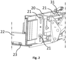
- FIG. 2 shows a perspective and sectional view of the leveling device.
- the main blade 20 is mounted on the frame 31 by at least two movable supports 21 in vertical translation.
- the main blade 20 is floating relative to the ground.
- Each mobile support 21 corresponds to axes secured to the frame relative to the main blade 20.
- the axes are housed in guides rectilinear of the frame.
- the rectilinear guides are oblong-shaped through openings.
- the two movable supports 21 are doubled on each side. In this case, on each side, there is a movable support 21 one below the other.
- an axis is inserted behind the main blade and makes it possible to block the movable support 21.
- the axis is inserted inside rectilinear guides of the frame 31.
- This figure shows a caster 23, which is mounted adjustable in height relative to the shoe and the main blade 20.
- the caster 23 is inside the shoe 22.
- This 23 wheel gives the device substantial advantages in terms of leveling accuracy and adaptability to varying ground conditions.
- each skate 22 of the device is equipped with a wheel 23.
- This wheel 23 is carefully connected to the skate 22 by a slide, thus allowing an adjustable degree of freedom.
- the height-adjustable 22-pad and 23-wheel offer several important advantages. They ensure optimal contact with the ground, regardless of the topography and nature of the terrain. This guarantees uniform, high-quality leveling, even on uneven surfaces. The ability to adjust the height of each 22-pad and 23-wheel also provides great adaptability, allowing the device to be quickly adjusted to terrain variations and the required leveling specifications.
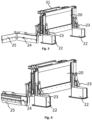
- FIGS 3 and 4 show two perspective views of the leveling device with the first side flap 24 and the second side flap 25.
- This embodiment features the provision of two separate side flaps: the first side flap 24 and the second side flap 25.
- Each side flap is designed for independent rotation around a specific vertical axis, thereby contributing to extending the overall width of the main blade 20 and optimizing the leveling process.
- the first side flap 24 is designed to be rotatable relative to a vertical axis of the main blade 20. This first side flap 24 is positioned so as to allow lateral extension of the main blade 20, thereby increasing the effective width of the leveling device. This independent rotation of the first side flap 24 makes it possible to quickly adapt the width of the device according to the specific leveling needs and the dimensions of the work area.
- the second side flap 25 is also designed to be rotatable about a vertical axis, but this time this axis is located on the first side flap 24. This mechanism allows the second side flap 25 to rotate about the first side flap 24, thus providing even greater flexibility in adjusting the width of the leveling device. The rotation of the second side flap 25 helps to optimize the lateral coverage of the main blade 20, thus adapting the device to specific terrain conditions and leveling requirements.
- the two side flaps When the two side flaps are positioned in a certain configuration, they help to extend the width of the main blade 20, creating a wider and more efficient leveling surface. This innovative design allows for faster and more accurate leveling, while minimizing the number of passes required over the surface to be treated.
- Each rotation is possible from an angle of 0 to 90°.
- the angle of the second flap relative to the first flap is between 0 and 150°.
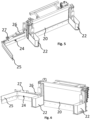
- FIGS 5 and 6 show another perspective view of the leveling device with the first side flap 24 and the second side flap 25.
- This embodiment features the use of rotating side flaps, each controlled by a double-acting hydraulic cylinder, thus allowing precise adjustment of the leveling configuration.
- the leveling device comprises a first lateral flap 24 which is capable of rotation around a vertical axis of a first double-acting hydraulic cylinder 26.
- This hydraulic cylinder makes it possible to control the rotation of the first lateral flap 24, thus allowing rapid adaptation of the working width of the main blade 20 according to the specific needs of the site.
- the second side flap 25 is positioned to be movable in rotation relative to a vertical axis located on the first side flap 24.
- This movement is made possible thanks to a second double-acting hydraulic cylinder 27 of the second side flap 25.
- This second hydraulic cylinder 27 makes it possible to adjust the angle and position of the second side flap 25, which contributes to optimal lateral coverage and precise adaptation to the characteristics of the terrain.
- Using double-acting hydraulic cylinders to control the side flaps offers several advantages. It allows for precise and independent control of each side flap, facilitating real-time adjustments to suit job site conditions. In addition, the hydraulic technology ensures rapid response and smooth handling of the side flaps, improving overall grading efficiency.
- FIG. 7 shows a view where the inside of the leveling device pad is visible.
- a through hole is visible to allow the caster to pass through.
- the caster is fixed to the skate and adjustable in height relative to it.
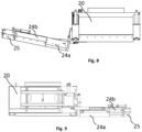
- THE figures 8 and 9 show a perspective view and a rear view of the leveling device.
- the first side flap assembly is composed of a first flap 24a and a first element 24b. According to one example, the sliding part is substantially equal to the width of the first side flap 24.
- Each of the first side flap 24 or the second side flap 25 is adapted to provide a positive or negative offset, which allows the horizontal position of the leveling device to be adjusted.
- FIG. 10 shows a perspective view of the leveling device with negative offset.
- the first side flap 24 is designed to allow a positive or negative offset. This means that it can be moved laterally relative to the main blade 20, either outwardly at a positive angle (positive offset) of approximately 12°, or at a negative angle (negative offset) of approximately 12°. This lateral movement of the first side flap 24 allows the horizontal position of the leveling device to be adjusted relative to the construction machine, thus providing adaptability to ground conditions and specific leveling needs.
- the second side flap 25 is also designed to allow for positive or negative offset. It can be moved laterally relative to the first side flap 24, thus providing additional horizontal adjustment of the device. This feature makes it possible to maximize the lateral coverage of the leveling device and achieve more precise leveling over a larger area.
- the leveling device can be positioned to reach hard-to-reach areas or to adapt to variations in the topography of the land.
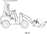
- FIG. 11 shows a construction machine with the leveling device and a rotating brush.
- the leveling device comprises a rotating brush 28 or an articulated sweeper.
- This The sweeper is mounted on the main blade by means of two axles fixed in the upper position, allowing multidirectional sweeping movement.
- a skate 22 and the second flap 25 are visible when folded down.
- the addition of the articulated sweeper on the main blade facilitates quick and efficient site cleaning. Thanks to its articulated design, the sweeper can adapt to terrain slopes precisely and adaptively.
- the sweeper follows the contours of the terrain, ensuring deep cleaning even in areas with uneven topography.
- the leveling device in this embodiment, therefore offers a significant advantage in terms of site cleaning. It helps keep work areas clean and clear, while significantly reducing the time required for cleaning. The increased efficiency resulting from the use of the articulated sweeper contributes to improving the overall efficiency of the work process on the site.
- a horizontal jib comprising a vertically adjustable free-rotating wheel is attached to the main blade. This device provides another reference and level support for leveling.
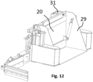
- THE figures 12 And 13 represent the entire device equipped with the hull in closed and open position.
- a part of the hull is open in pivot connection with the main blade and actuated by a jack fixed to the main blade 20.
- the leveling device has the main blade provided with a portion similar to a bucket shell 29, designed specifically for transporting materials. This portion, incorporated into the main blade, provides additional functionality to the device, thus enabling efficient and convenient handling of materials on the construction site.
- this 29 bucket shell type part brings significant advantages to the surface preparation and site work process. This feature allows materials to be brought into the areas where they are needed very quickly. The operator can load the bucket shell part 29 with the appropriate materials and transport them directly to the areas to be treated. This approach significantly reduces the time required to deliver the necessary materials, thus increasing the efficiency of operations.
- this same bucket shell 29-type part also allows for the removal of excess materials efficiently.
- the operator can load them into the bucket shell 29 and quickly remove them from the site, thus avoiding unnecessary accumulations and helping to maintain order and cleanliness.
- the combination of the main blade with this bucket shell-type part 29 gives the device increased versatility and utility on the jobsite. By providing a convenient and fast method for transporting materials, this feature improves productivity while reducing potential delays related to the availability of necessary materials.
Landscapes
- Engineering & Computer Science (AREA)
- Mechanical Engineering (AREA)
- Mining & Mineral Resources (AREA)
- Civil Engineering (AREA)
- General Engineering & Computer Science (AREA)
- Structural Engineering (AREA)
- Road Paving Machines (AREA)
- Road Repair (AREA)
Applications Claiming Priority (1)
| Application Number | Priority Date | Filing Date | Title |
|---|---|---|---|
| FR2310242A FR3153355B1 (fr) | 2023-09-27 | 2023-09-27 | Dispositif de nivelage pour engin de chantier et ensemble d’un engin de chantier portant un tel dispositif |
Publications (1)
| Publication Number | Publication Date |
|---|---|
| EP4530408A1 true EP4530408A1 (de) | 2025-04-02 |
Family
ID=89158558
Family Applications (1)
| Application Number | Title | Priority Date | Filing Date |
|---|---|---|---|
| EP24202737.3A Withdrawn EP4530408A1 (de) | 2023-09-27 | 2024-09-26 | Nivelliervorrichtung für eine baumaschine und anordnung einer baumaschine mit einer solchen vorrichtung |
Country Status (2)
| Country | Link |
|---|---|
| EP (1) | EP4530408A1 (de) |
| FR (1) | FR3153355B1 (de) |
Citations (9)
| Publication number | Priority date | Publication date | Assignee | Title |
|---|---|---|---|---|
| US4074448A (en) * | 1976-06-17 | 1978-02-21 | Niemela W Wally | Hinged snowplow, conversion kit, and method therefor |
| US5819444A (en) * | 1996-06-20 | 1998-10-13 | Desmarais; Denis | Snow blade with tiltable lateral panels |
| US20090077834A1 (en) * | 2007-09-25 | 2009-03-26 | Assaloni 1920 S.R.L. | Snowplough Blade With Adjustable Width |
| US20100326684A1 (en) | 2006-04-05 | 2010-12-30 | Mullett Myron L | Road Grader/Spreader System and Method |
| US20170218597A1 (en) * | 2016-02-01 | 2017-08-03 | Stonebrooke Equipment Inc. | Plow assembly with valve system for wings |
| US9896811B2 (en) * | 2012-03-16 | 2018-02-20 | Multihog R & D Limited | Apparatus for removing unwanted material from the ground |
| US20190040606A1 (en) | 2018-10-10 | 2019-02-07 | John V. Armstrong | Box Blade Earth Grading Implement |
| US20210131059A1 (en) | 2019-11-06 | 2021-05-06 | Tylan Thiessen | Floating earth levelling blade assembly with shoes |
| US20220090347A1 (en) * | 2020-09-18 | 2022-03-24 | Great Plains Manufacturing, Inc. | Multipurpose bucket |
-
2023
- 2023-09-27 FR FR2310242A patent/FR3153355B1/fr active Active
-
2024
- 2024-09-26 EP EP24202737.3A patent/EP4530408A1/de not_active Withdrawn
Patent Citations (9)
| Publication number | Priority date | Publication date | Assignee | Title |
|---|---|---|---|---|
| US4074448A (en) * | 1976-06-17 | 1978-02-21 | Niemela W Wally | Hinged snowplow, conversion kit, and method therefor |
| US5819444A (en) * | 1996-06-20 | 1998-10-13 | Desmarais; Denis | Snow blade with tiltable lateral panels |
| US20100326684A1 (en) | 2006-04-05 | 2010-12-30 | Mullett Myron L | Road Grader/Spreader System and Method |
| US20090077834A1 (en) * | 2007-09-25 | 2009-03-26 | Assaloni 1920 S.R.L. | Snowplough Blade With Adjustable Width |
| US9896811B2 (en) * | 2012-03-16 | 2018-02-20 | Multihog R & D Limited | Apparatus for removing unwanted material from the ground |
| US20170218597A1 (en) * | 2016-02-01 | 2017-08-03 | Stonebrooke Equipment Inc. | Plow assembly with valve system for wings |
| US20190040606A1 (en) | 2018-10-10 | 2019-02-07 | John V. Armstrong | Box Blade Earth Grading Implement |
| US20210131059A1 (en) | 2019-11-06 | 2021-05-06 | Tylan Thiessen | Floating earth levelling blade assembly with shoes |
| US20220090347A1 (en) * | 2020-09-18 | 2022-03-24 | Great Plains Manufacturing, Inc. | Multipurpose bucket |
Also Published As
| Publication number | Publication date |
|---|---|
| FR3153355B1 (fr) | 2026-01-30 |
| FR3153355A1 (fr) | 2025-03-28 |
Similar Documents
| Publication | Publication Date | Title |
|---|---|---|
| US11396734B2 (en) | Trenching system with hydraulically adjustable hub | |
| US8002360B2 (en) | Adjustable planer system | |
| FR2640299A1 (fr) | Machine niveleuse de chaussee | |
| CA2925072C (fr) | Equipement de formage de surfaces, procede de fabrication et utilisation de l'equipement de formage de surfaces et unite mobile incluant l'equipement de formage de surfaces | |
| US10876260B2 (en) | Accurate tool depth control | |
| WO2010119186A1 (fr) | L'invention concerne un dispositif multifonction pour terrassement, nivellement et compactage | |
| JP2019060209A (ja) | 建設機械の排土装置 | |
| EP4530408A1 (de) | Nivelliervorrichtung für eine baumaschine und anordnung einer baumaschine mit einer solchen vorrichtung | |
| US6367177B1 (en) | Trench restoration apparatus | |
| CN104080978A (zh) | 用于修复边缘的设备及其方法 | |
| FR2718170A1 (fr) | Outil auxiliaire multifonctions lame niveleuse à patins vibrants pour la construction de remblais routiers et autres. | |
| CA2062832A1 (fr) | Machine finisseuse niveleuse multifonction pour la construction de remblais routiers et autres | |
| EP1533422A1 (de) | Vorrichtung zum Sanieren, Nivellieren und Verdichten von nicht asphaltierten Strassen | |
| FR2504829A1 (fr) | Dispositif de creusement de rigoles de hauts fourneaux et analogues | |
| EP2732098B1 (de) | Verfahren zur bodenverdichtung | |
| JPS60261810A (ja) | 支持車両に取り付けて使用するアタツチメント装置 | |
| JP2001049685A (ja) | 油圧ショベルのブレード装置 | |
| DK181255B1 (en) | Tool for removing gravel | |
| EP0790354B1 (de) | Gerät zum Einsetzen einer aktiven Fuge in einem Bauwerk, Vorrichtung und Verfahren dafür | |
| JP2001040697A (ja) | 掘削溝用敷き均し装置 | |
| FR3063294A1 (fr) | Machine tractee destinee notamment a la reparation et l'entretien des sols, et en particulier de chaussees | |
| WO2000026470A1 (fr) | Appareil pour la reparation et l'entretien de routes goudronnees | |
| FR2650316A1 (fr) | Procede et machine pour la construction de remblais routiers et autres qui pousse les materiaux et les camions et scarifie | |
| EP0085790B1 (de) | Bauzug zur Erneuerung einer Eisenbahnschienenstrecke | |
| JP2001098578A (ja) | ホッパ装置 |
Legal Events
| Date | Code | Title | Description |
|---|---|---|---|
| PUAI | Public reference made under article 153(3) epc to a published international application that has entered the european phase |
Free format text: ORIGINAL CODE: 0009012 |
|
| STAA | Information on the status of an ep patent application or granted ep patent |
Free format text: STATUS: THE APPLICATION HAS BEEN PUBLISHED |
|
| AK | Designated contracting states |
Kind code of ref document: A1 Designated state(s): AL AT BE BG CH CY CZ DE DK EE ES FI FR GB GR HR HU IE IS IT LI LT LU LV MC ME MK MT NL NO PL PT RO RS SE SI SK SM TR |
|
| STAA | Information on the status of an ep patent application or granted ep patent |
Free format text: STATUS: THE APPLICATION IS DEEMED TO BE WITHDRAWN |
|
| 18D | Application deemed to be withdrawn |
Effective date: 20251003 |