EP4530405A1 - Luftstromvorrichtung und handhaartrockner - Google Patents
Luftstromvorrichtung und handhaartrockner Download PDFInfo
- Publication number
- EP4530405A1 EP4530405A1 EP23851597.7A EP23851597A EP4530405A1 EP 4530405 A1 EP4530405 A1 EP 4530405A1 EP 23851597 A EP23851597 A EP 23851597A EP 4530405 A1 EP4530405 A1 EP 4530405A1
- Authority
- EP
- European Patent Office
- Prior art keywords
- fan
- equal
- airflow device
- assembly
- guide vane
- Prior art date
- Legal status (The legal status is an assumption and is not a legal conclusion. Google has not performed a legal analysis and makes no representation as to the accuracy of the status listed.)
- Pending
Links
Images


Classifications
-
- F—MECHANICAL ENGINEERING; LIGHTING; HEATING; WEAPONS; BLASTING
- F04—POSITIVE - DISPLACEMENT MACHINES FOR LIQUIDS; PUMPS FOR LIQUIDS OR ELASTIC FLUIDS
- F04D—NON-POSITIVE-DISPLACEMENT PUMPS
- F04D29/00—Details, component parts, or accessories
- F04D29/40—Casings; Connections of working fluid
- F04D29/403—Casings; Connections of working fluid especially adapted for elastic fluid pumps
-
- A—HUMAN NECESSITIES
- A01—AGRICULTURE; FORESTRY; ANIMAL HUSBANDRY; HUNTING; TRAPPING; FISHING
- A01G—HORTICULTURE; CULTIVATION OF VEGETABLES, FLOWERS, RICE, FRUIT, VINES, HOPS OR SEAWEED; FORESTRY; WATERING
- A01G20/00—Cultivation of turf, lawn or the like; Apparatus or methods therefor
- A01G20/40—Apparatus for cleaning the lawn or grass surface
- A01G20/43—Apparatus for cleaning the lawn or grass surface for sweeping, collecting or disintegrating lawn debris
- A01G20/47—Vacuum or blower devices
-
- E—FIXED CONSTRUCTIONS
- E01—CONSTRUCTION OF ROADS, RAILWAYS, OR BRIDGES
- E01H—STREET CLEANING; CLEANING OF PERMANENT WAYS; CLEANING BEACHES; DISPERSING OR PREVENTING FOG IN GENERAL CLEANING STREET OR RAILWAY FURNITURE OR TUNNEL WALLS
- E01H1/00—Removing undesirable matter from roads or like surfaces, with or without moistening of the surface
- E01H1/08—Pneumatically dislodging or taking-up undesirable matter or small objects; Drying by heat only or by streams of gas; Cleaning by projecting abrasive particles
- E01H1/0809—Loosening or dislodging by blowing ; Drying by means of gas streams
-
- E—FIXED CONSTRUCTIONS
- E01—CONSTRUCTION OF ROADS, RAILWAYS, OR BRIDGES
- E01H—STREET CLEANING; CLEANING OF PERMANENT WAYS; CLEANING BEACHES; DISPERSING OR PREVENTING FOG IN GENERAL CLEANING STREET OR RAILWAY FURNITURE OR TUNNEL WALLS
- E01H1/00—Removing undesirable matter from roads or like surfaces, with or without moistening of the surface
- E01H1/08—Pneumatically dislodging or taking-up undesirable matter or small objects; Drying by heat only or by streams of gas; Cleaning by projecting abrasive particles
- E01H1/0863—Apparatus loosening or removing the dirt by blowing and subsequently dislodging it at least partially by suction ; Combined suction and blowing nozzles
-
- F—MECHANICAL ENGINEERING; LIGHTING; HEATING; WEAPONS; BLASTING
- F04—POSITIVE - DISPLACEMENT MACHINES FOR LIQUIDS; PUMPS FOR LIQUIDS OR ELASTIC FLUIDS
- F04D—NON-POSITIVE-DISPLACEMENT PUMPS
- F04D19/00—Axial-flow pumps
- F04D19/002—Axial flow fans
-
- F—MECHANICAL ENGINEERING; LIGHTING; HEATING; WEAPONS; BLASTING
- F04—POSITIVE - DISPLACEMENT MACHINES FOR LIQUIDS; PUMPS FOR LIQUIDS OR ELASTIC FLUIDS
- F04D—NON-POSITIVE-DISPLACEMENT PUMPS
- F04D25/00—Pumping installations or systems
- F04D25/02—Units comprising pumps and their driving means
- F04D25/06—Units comprising pumps and their driving means the pump being electrically driven
- F04D25/0673—Battery powered
-
- F—MECHANICAL ENGINEERING; LIGHTING; HEATING; WEAPONS; BLASTING
- F04—POSITIVE - DISPLACEMENT MACHINES FOR LIQUIDS; PUMPS FOR LIQUIDS OR ELASTIC FLUIDS
- F04D—NON-POSITIVE-DISPLACEMENT PUMPS
- F04D25/00—Pumping installations or systems
- F04D25/02—Units comprising pumps and their driving means
- F04D25/08—Units comprising pumps and their driving means the working fluid being air, e.g. for ventilation
- F04D25/084—Units comprising pumps and their driving means the working fluid being air, e.g. for ventilation hand fans
-
- F—MECHANICAL ENGINEERING; LIGHTING; HEATING; WEAPONS; BLASTING
- F04—POSITIVE - DISPLACEMENT MACHINES FOR LIQUIDS; PUMPS FOR LIQUIDS OR ELASTIC FLUIDS
- F04D—NON-POSITIVE-DISPLACEMENT PUMPS
- F04D29/00—Details, component parts, or accessories
- F04D29/26—Rotors specially for elastic fluids
- F04D29/32—Rotors specially for elastic fluids for axial flow pumps
- F04D29/325—Rotors specially for elastic fluids for axial flow pumps for axial flow fans
-
- F—MECHANICAL ENGINEERING; LIGHTING; HEATING; WEAPONS; BLASTING
- F04—POSITIVE - DISPLACEMENT MACHINES FOR LIQUIDS; PUMPS FOR LIQUIDS OR ELASTIC FLUIDS
- F04D—NON-POSITIVE-DISPLACEMENT PUMPS
- F04D29/00—Details, component parts, or accessories
- F04D29/40—Casings; Connections of working fluid
- F04D29/52—Casings; Connections of working fluid for axial pumps
- F04D29/54—Fluid-guiding means, e.g. diffusers
- F04D29/541—Specially adapted for elastic fluid pumps
- F04D29/542—Bladed diffusers
- F04D29/544—Blade shapes
-
- F—MECHANICAL ENGINEERING; LIGHTING; HEATING; WEAPONS; BLASTING
- F04—POSITIVE - DISPLACEMENT MACHINES FOR LIQUIDS; PUMPS FOR LIQUIDS OR ELASTIC FLUIDS
- F04D—NON-POSITIVE-DISPLACEMENT PUMPS
- F04D29/00—Details, component parts, or accessories
- F04D29/40—Casings; Connections of working fluid
- F04D29/52—Casings; Connections of working fluid for axial pumps
- F04D29/54—Fluid-guiding means, e.g. diffusers
- F04D29/541—Specially adapted for elastic fluid pumps
- F04D29/545—Ducts
-
- F—MECHANICAL ENGINEERING; LIGHTING; HEATING; WEAPONS; BLASTING
- F04—POSITIVE - DISPLACEMENT MACHINES FOR LIQUIDS; PUMPS FOR LIQUIDS OR ELASTIC FLUIDS
- F04D—NON-POSITIVE-DISPLACEMENT PUMPS
- F04D29/00—Details, component parts, or accessories
- F04D29/66—Combating cavitation, whirls, noise, vibration or the like; Balancing
- F04D29/68—Combating cavitation, whirls, noise, vibration or the like; Balancing by influencing boundary layers
- F04D29/681—Combating cavitation, whirls, noise, vibration or the like; Balancing by influencing boundary layers especially adapted for elastic fluid pumps
- F04D29/682—Combating cavitation, whirls, noise, vibration or the like; Balancing by influencing boundary layers especially adapted for elastic fluid pumps by fluid extraction
-
- F—MECHANICAL ENGINEERING; LIGHTING; HEATING; WEAPONS; BLASTING
- F04—POSITIVE - DISPLACEMENT MACHINES FOR LIQUIDS; PUMPS FOR LIQUIDS OR ELASTIC FLUIDS
- F04D—NON-POSITIVE-DISPLACEMENT PUMPS
- F04D29/00—Details, component parts, or accessories
- F04D29/66—Combating cavitation, whirls, noise, vibration or the like; Balancing
- F04D29/68—Combating cavitation, whirls, noise, vibration or the like; Balancing by influencing boundary layers
- F04D29/681—Combating cavitation, whirls, noise, vibration or the like; Balancing by influencing boundary layers especially adapted for elastic fluid pumps
- F04D29/684—Combating cavitation, whirls, noise, vibration or the like; Balancing by influencing boundary layers especially adapted for elastic fluid pumps by fluid injection
-
- F—MECHANICAL ENGINEERING; LIGHTING; HEATING; WEAPONS; BLASTING
- F05—INDEXING SCHEMES RELATING TO ENGINES OR PUMPS IN VARIOUS SUBCLASSES OF CLASSES F01-F04
- F05D—INDEXING SCHEME FOR ASPECTS RELATING TO NON-POSITIVE-DISPLACEMENT MACHINES OR ENGINES, GAS-TURBINES OR JET-PROPULSION PLANTS
- F05D2250/00—Geometry
- F05D2250/10—Two-dimensional
- F05D2250/19—Two-dimensional machined; miscellaneous
- F05D2250/191—Two-dimensional machined; miscellaneous perforated
Definitions
- an airflow device By rotating fan blades, an airflow device drives gas to flow to do work, thereby implementing the main function of the airflow device.
- the airflow device may be a blower, a blow-suction machine, or the like.
- the blower is widely used in gardens, streets, homes, and other environments.
- the noise of the airflow device is affected by many factors, and the noise may further increase when the flow rate of the blown gas increases.
- users have higher requirements on the noise generated by the airflow device in operation.
- At least one of the multiple through holes is basically circular, and the hole diameter D3 of the multiple through holes is greater than or equal to 2 mm and less than or equal to 5 mm.
- the fan blade support portion 253 supports the fan blades 252, and the hub ratio is defined as the ratio of the maximum first diameter formed by the fan blade support portion to the second diameter formed by the outermost edges of the fan blades, where the hub ratio is greater than or equal to 0.4 and less than or equal to 0.5.
- the first distance L1 is formed between a guide vane root of the guide vane and the fan blade, where the first distance is greater than or equal to 5 mm and less than or equal to 30 mm.
- a guide vane root of the guide vane intersects with a guide vane support portion
- the fan assembly includes a fan front end located on the front side and a fan rear end located on the rear side
- the guide vane support portion includes a first rear edge located on the rear side
- the second distance L2 is defined as the distance between the fan front end of the fan assembly and the first rear edge of the guide vane support portion, where the second distance is greater than or equal to 3 mm and less than or equal to 6 mm.
- the radial thickness L3 of the guide vane is greater than or equal to 9 mm and less than or equal to 15 mm.
- an opening rate of the guide vane is defined as the ratio of the total opening area of the guide vane to the total radial area of the guide vane, where the opening rate is greater than or equal to 10% and less than or equal to 75%.
- the ratio T/D of the average wall thickness T of the pipe assembly to the inner diameter D of the pipe assembly is greater than or equal to 1:50 and less than or equal to 1:15.
- the airflow device is a blower, a blow-suction machine, or another device that performs work through the airflow.
- An airflow device includes a grip for a user to hold; a pipe assembly for the air to pass through; a fan assembly including fan blades and a fan blade support portion supporting the fan blades, where the fan blades are rotatable about a fan axis, and the fan assembly is an axial flow fan; a motor for driving the fan assembly to rotate; and guide vanes for directing the airflow.
- the inner diameter of the pipe assembly is greater than or equal to 90 mm.
- the flow rate of the airflow device is greater than or equal to 1000 CFM.
- the maximum rotational speed of the motor is less than 35000 rpm.
- the first distance is formed between a guide vane root of the guide vane and the fan blade, where the first distance is greater than or equal to 5 mm and less than or equal to 30 mm.
- the first distance is formed between a guide vane root of the guide vane and the fan blade, where the first distance is greater than or equal to 5 mm and less than or equal to 20 mm.
- the pipe assembly includes a first pipe and a second pipe, where the first pipe is located on the front side of the second pipe.
- the average wall thickness of the pipe assembly is greater than or equal to 3 mm.
- the hub ratio is defined as the ratio of the maximum first diameter formed by the fan blade support portion to the second diameter formed by the outermost edges of the fan blades, where the hub ratio is greater than or equal to 0.4 and less than or equal to 0.5.
- a guide vane root of the guide vane intersects with a guide vane support portion
- the fan assembly includes a fan front end located on the front side and a fan rear end located on the rear side
- the guide vane support portion includes a first rear edge located on the rear side
- the second distance L2 is defined as the distance between the fan front end of the fan assembly and the first rear edge of the guide vane support portion, where the second distance is greater than or equal to 3 mm and less than or equal to 6 mm.
- the airflow device includes a body, where the body includes the fan assembly, the motor, and a housing, and the housing is formed with the grip; the airflow device further includes a wind tube, the wind tube is detachably connected to the body, and the wind tube allows the air to pass through; the airflow device is provided with an ejection mechanism, and the ejection mechanism applies an ejection force so that the wind tube tends to be separated from the body.
- the airflow device includes a battery pack coupling portion configured to mount a battery pack for supplying power to the airflow device.
- the airflow device is a blower, a blow-suction machine, or another device that performs work through the airflow.
- the airflow device further includes a handle used for the user to hold and located on the front side of the grip.
- guide vanes for directing the airflow are further included, where the guide vane includes multiple through holes penetrating at least part of the guide vane.
- an opening rate of the guide vane is defined as the ratio of the total opening area of the guide vane to the total radial area of the guide vane, where the opening rate is greater than or equal to 10% and less than or equal to 75%.
- the ratio T/D of the average wall thickness T of the pipe assembly to the inner diameter D of the pipe assembly is greater than or equal to 1:50 and less than or equal to 1:15.
- the airflow device is capable of being connected to a belt for use, a blower is provided with a belt coupling portion, the belt is provided with a belt mounting portion, and the belt coupling portion and the belt mounting portion are assembled so that the belt is mounted to the blower.
- An airflow device includes a grip for a user to hold; a pipe assembly for the air to pass through; a fan assembly including fan blades and a fan blade support portion supporting the fan blades, where the fan blades are rotatable about a fan axis of the fan assembly, and the fan assembly is an axial flow fan; and a motor for driving the fan assembly to rotate.
- the airflow device further includes a handle used for the user to hold and located on the front side of the grip, the flow rate of the airflow device is greater than or equal to 1000 CFM, and the maximum rotational speed of the motor is less than 35000 rpm.
- guide vanes for directing the airflow are further included, where along the direction of the fan axis, the first distance is formed between a guide vane root of the guide vane and the fan blade, where the first distance is greater than or equal to 5 mm and less than or equal to 20 mm.
- An airflow device includes a grip for a user to hold; a pipe assembly for the air to pass through; a fan assembly including fan blades and a fan blade support portion supporting the fan blades, where the fan blades are rotatable about a fan axis, and the fan assembly is an axial flow fan; a motor for driving the fan assembly to rotate; and guide vanes for directing the airflow.
- the hub ratio is defined as the ratio of the maximum first diameter D1 formed by the fan blade support portion to the second diameter D2 formed by the outermost edges of the fan blades, where the hub ratio is less than or equal to 0.5.
- the maximum rotational speed of the motor is less than 30000 rpm.
- the inner diameter of the pipe assembly is greater than or equal to 90 mm.
- the flow rate of the airflow device is greater than or equal to 1000 CFM.
- a guide vane includes multiple through holes penetrating at least part of the guide vane.
- the first distance L1 is formed between a guide vane root of a guide vane and the fan blade, where the first distance is greater than or equal to 5 mm and less than or equal to 30 mm.
- a guide vane root of a guide vane intersects with a guide vane support portion
- the fan assembly includes a fan front end located on the front side and a fan rear end located on the rear side
- the guide vane support portion includes a first rear edge located on the rear side
- the second distance L2 is defined as the distance between the fan front end of the fan assembly and the first rear edge of the guide vane support portion, where the second distance is greater than or equal to 3 mm and less than or equal to 6 mm.
- the average wall thickness of the pipe assembly is greater than or equal to 3 mm.
- An airflow device includes a grip for a user to hold; a pipe assembly for the air to pass through; fan blades rotatable about a fan axis; a motor for driving the fan assembly to rotate; and guide vanes for directing the airflow.
- the average wall thickness T of the pipe assembly is greater than 3 mm.
- the product T*D of the average wall thickness T of the pipe assembly and the inner diameter D of the pipe assembly is greater than or equal to 2700 mm ⁇ mm, and the ratio T/D of the average wall thickness T of the pipe assembly to the inner diameter D of the pipe assembly is greater than or equal to 1:50 and less than or equal to 1:15.
- the flow rate of the airflow device is greater than or equal to 1000 CFM.
- the inner diameter of the pipe assembly is greater than or equal to 90 mm.
- the maximum rotational speed of the motor is less than 30000 rpm.
- the average wall thickness T of the pipe assembly is greater than or equal to 3.5 mm.
- a conical pipe is formed inside the pipe assembly, the conical pipe extends from a first end located on the front side of the pipe assembly, the conical pipe accommodates at least part of the motor, the distance by which the conical pipe extends from the first end is the fourth distance L4, the guide vane includes a third end facing the fan blade and a fourth end facing away from the fan blade, the distance from the fourth end to the first end is the fifth distance L5, and the ratio L4/L5 of the fourth distance to the fifth distance is greater than or equal to 0 and less than or equal to 0.1.
- a conical pipe is formed inside the pipe assembly, the conical pipe extends from a first end located on the front side of the pipe assembly, the conical pipe accommodates at least part of the motor, the guide vane includes a third end facing the fan blade and a fourth end facing away from the fan blade, the distance from the fourth end to the first end is the fifth distance L5, and the fifth distance is approximately 0.
- the airflow device includes a battery pack coupling portion configured to mount a battery pack for supplying power to the airflow device.
- the airflow device is a blower, a blow-suction machine, or another device that performs work through the airflow.
- An airflow device includes a grip for a user to hold; a pipe assembly for the air to pass through; a fan assembly including fan blades and a fan blade support portion supporting the fan blades, where the fan blades are rotatable about a fan axis of the fan assembly; and a motor for driving the fan assembly to rotate.
- the airflow device further includes a handle used for the user to hold and located on the front side of the grip, and the air volume of the airflow device is greater than 1000 CFM.
- the handle is rotatable about a handle axis, the angle of rotation of the handle is ⁇ , and the angle of rotation ⁇ is greater than 10 degrees and less than or equal to 150 degrees.
- the handle has at least one lockable position.
- a housing is further included, where the pipe assembly is connected to the housing, and the handle is detachably connected to the housing.
- a housing and a mounting assembly are further included, where the handle is mounted to the housing through the mounting assembly, and the mounting assembly enables the handle to rotate about a handle axis and enables the handle to be locked at any angle during a rotation process.
- the mounting assembly includes a trigger, a rotary shaft, and a fastener
- the rotary shaft passes through the housing and the handle
- the fastener is detachably connected to an end of the rotary shaft
- the trigger is hinged to the other end of the rotary shaft
- the trigger is rotatable relative to the rotary shaft so that the trigger has a locking position and an unlocking position, where when the trigger is at the locking position, the handle is clamped between the fastener and the trigger, and when the trigger is at the unlocking position, the handle is rotatable relative to the rotary shaft.
- an illumination device disposed on the front side of the handle is further included.
- the inner diameter of the pipe assembly is D
- the width of the handle along the left and right direction is W
- W/D is greater than or equal to 1 and less than or equal to 2.5.
- the looped portion has a first height M1 along the up and down direction
- the shielding portion has a first length M3 along the left and right direction, where the first length M3 is greater than or equal to the first height M1.
- the airflow device may be a fan.
- the airflow device may be a blower, a blow-suction machine, or another device that needs to blow or suck the airflow to do work.
- the blower accelerates the air through the rotation of the fan and pushes an object to be moved through the airflow.
- the blow-suction machine has two functions: blowing and suction so that the blow-suction machine can push the object through the airflow and suck the object through the airflow.
- the blower and the blow-suction machine are often used in fields such as garden cleaning.
- blower 10 The technical solution of the present application is described below using a blower 10 as an example.
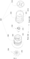
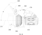
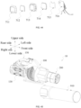
- the blower 10 includes a housing 100, a blow-suction structure 200, and a power supply system.
- the housing 100 forms an accommodation space that can accommodate at least part of the blow-suction structure 200, and the housing 100 is formed with or connected to a grip 150 for the user to hold.
- the blow-suction structure 200 includes functional assemblies for implementing blowing and suction functions, such as a motor 230, a fan assembly 250, and guide vanes 282.
- the blow-suction structure 200 further includes a pipe assembly 260 for fixing and accommodating the preceding functional assemblies and providing a channel for the airflow.
- a vent cover 300 is used for sucking air into the blow-suction structure 200. In this example, the vent cover 300 is grid-shaped.
- the housing 100 connects and fixes the vent cover 300 to the blow-suction structure 200. Air is sucked into the blower 10 through the vent cover 300 and driven by the fan assembly 250 in the blow-suction structure 200 to be blown out from a first end 201 of the blow-suction structure 200.
- the first bracket 112 and the second bracket 122 support the blow-suction structure 200 so that the blower 10 does not fall over.
- the grip 150 may be provided independently of the housing 100, that is to say, the grip 150 may not be formed by extending from the housing 100.
- the pipe assembly 260 is connected to the housing 100, and at least part of the pipe assembly 260 is wrapped and/or fixed by the housing 100.
- the pipe assembly 260 is used for the air to pass through and includes a first end 201 and a second end 202. At least part of the airflow flows between the first end 201 and the second end 202.
- the rotation of the motor 230 drives fan blades 252 to rotate so that the air outside the blower 10 enters the second end 202 of the pipe assembly 260 from the vent cover 300, flows through the fan blades 252, the guide vanes 282, and a conical pipe 223 in sequence, and finally flows out from the first end 201 of the pipe assembly 260.
- the blow-suction machine when the blow-suction machine is in a suction mode, the airflow flows in a direction opposite to that in the preceding blower.
- the fan assembly 250 includes fan blades 252 and a fan blade support portion 253, and the fan blades 252 are mounted on the fan blade support portion 253 or integrally formed with the fan blade support portion 253.
- the fan blades 252 are rotatable about a fan axis 251.
- the fan assembly 250 may be an axial flow fan or a centrifugal fan.
- the motor 230 includes a motor output shaft 232, the motor output shaft 232 extends along a motor axis 231, and the fan axis 251 of the fan blades 252 basically coincides with the motor axis 231.
- a rear end 254 (referring to FIG. 7 ) of the fan assembly 250 has a hollow structure inside.
- the motor output shaft 232 extends into the fan blade support portion 253 of the fan assembly 250.
- the motor output shaft 232 and the fan assembly 250 are fixed by screws.
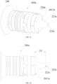
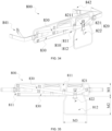
- FIG. 4 and FIGS. 9 to 14 disclose the structures of a second pipe 240 and the guide vanes 282 therein.
- the pipe assembly 260 includes a first pipe 220 and a second pipe 240.
- the guide vanes 282 include first guide vanes 242 and second guide vanes 222.
- the first guide vanes 242 are located in the second pipe 240, and the second guide vanes 222 are located in the first pipe 220.
- the blower 10 further includes a guide vane support portion 281 for supporting the guide vanes 282.
- the guide vane support portion 281 includes a first guide vane support portion 241 and a second guide vane support portion 221.
- the first guide vane support portion 241 supports the first guide vanes 242, and the second guide vane support portion 221 supports the second guide vanes 222.
- a guide vane root 2431 of the first guide vane 242 is located on the first guide vane support portion 241, and the first guide vane 242 connects the first guide vane support portion 241 to an outer housing of the second pipe 240.
- three first guide vanes 242 are disposed on the first guide vane support portion 241.
- the first guide vane support portion 241 forms an accommodation space for accommodating at least part of the motor 230.
- the screw passes through a mounting hole 246 to fix the motor 230 into the second pipe 240.
- a guide vane axis 249 passes through the center of the first guide vane 242.
- the first guide vanes 242 are arranged at intervals in the circumferential direction of the guide vane axis 249.
- the first guide vanes 242 and the first guide vane support portion 241 extend basically along the radial direction of the guide vane axis 249.
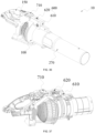
- the pipe assembly 260 further includes a protective cover 210, and the protective cover 210 is not the guide vane 282.
- the protective cover 210 is disposed at the frontmost side of the conical pipe 223 and may be used for reminding the operator not to put hands into the blower 10.
- four ribs are provided on the protective cover 210, and three guide vanes 282 are provided.
- the guide vanes 282 are disposed between the fan blades 252 and the protective cover 210, and the guide vanes 282 are disposed between the fan blades 252 and the conical pipe 223.
- the second guide vane support portion 221 extends forward and is connected to the conical pipe 223.
- the guide vanes 282 surround and support the conical pipe 223.
- the airflow flows in through the vent cover 300 of the second end 202 of the blower 10 and is accelerated by the fan blades 252
- the airflow is guided by the guide vanes 282 to flow along the outer wall of the conical pipe 223 to an air port 2231 on the front side of the conical pipe 223.
- a part of the airflow passes through the protective cover 210 and flows out from the second end 201 of the blower 10, and the other part of the airflow flows back from the air port 2231 to the motor 230 to help the motor dissipate heat.
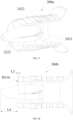
- the first guide vane 242 includes multiple through holes 243 penetrating at least part of the first guide vane 242.
- each first guide vane 242 is provided with multiple through holes 243.
- the radial thickness L3 of the first guide vane 242 is greater than or equal to 9 mm and less than or equal to 15 mm. In an example, the radial thickness L3 is about 11 mm. In an example, the radial thickness L3 is about 13 mm.
- At least one of the multiple through holes 242 is basically circular, and the hole diameter D3 of each of the multiple through holes 242 is greater than or equal to 2 mm and less than or equal to 5 mm.
- the hole diameter D3 is about 2.5 mm.
- the hole diameter D3 is about 3 mm.
- the hole diameter D3 is about 3.5 mm.
- the hole diameter D3 is about 4 mm.
- the shapes of the multiple through holes 243 are not limited as long as the fluid such as air can pass through the inside of the multiple through holes 243.
- basically circular includes both a circle in the geometric sense and an ellipse with a ratio of the major axis length to the minor axis length being between 0.9 and 1.1.
- the multiple through holes 243 penetrates the first guide vane 242 along a through hole axis 2432, and the through hole axis 2432 is basically parallel to the fan axis 251 of the fan assembly 250. Since the fan axis 251 is basically parallel to the guide vane axis 249, the through hole axis 2432 is also basically parallel to the guide vane axis 249.
- the "punching direction" of the multiple through holes 243 is basically consistent with the motion direction of the fluid such as air.
- the multiple through holes 243 penetrate the first guide vane 242 along through hole axes 2432, and the through hole axes 2432 are basically parallel to the fan axis 251 of the fan assembly 250.
- the through hole axes 2432 are also basically parallel to the guide vane axis 249 and the fan axis 251.
- the through hole axes 2432 of the multiple through holes 243 may form an included angle with the guide vane axis 249, and the included angle is greater than 0 degrees and less than or equal to 50 degrees. Within this angle range, the multiple through holes 243 guide the flow direction of the fluid to a certain extent, thereby reducing the vibration and noise generated when the fluid "collides" with the first guide vanes 242.
- the included angle may be 10 degrees, 20 degrees, or 30 degrees.
- basically parallel includes both absolute parallelism of two axes in the geometric sense and a state in which the included angle between the two axes is relatively small, such as a state in which the included angle between the two axes is within 10 degrees.
- the first guide vane 242 includes at least a first surface 2421 and a second surface 2422.
- the first surface 2421 is an outwardly convex surface
- the second surface 2422 is an inwardly concave surface.
- the opening rate of the first guide vane 242 is defined as the ratio of the total opening area of the first guide vane 242 to the total area of the first guide vane 242, and the opening rate is greater than or equal to 10% and less than or equal to 75%. In an example, the opening rate is greater than or equal to 20% and less than or equal to 50%. In an example, the opening rate may be 25%, 30%, or 40%.
- Limiting the range of the opening rate is equivalent to limiting the proportion of the fluid that can flow through the inside of the first guide vane 242 so that while the guiding capability of the first guide vane 242 is not greatly reduced, the degree of the impact between the fluid and the first surface 2421 of the first guide vane 242 can be reduced, thereby reducing the vibration and noise.
- the space formed between two adjacent guide vanes 282 is not the multiple through holes 243 mentioned in the present application, and the multiple through holes 243 are formed on the same guide vane 282.
- the opening rate is also for the same guide vane 282.
- different guide vanes 282 on the same blower 10 may have different opening rates, and different guide vanes 282 on the same blower 10 may have different through-hole shapes.
- FIG. 5 is a partial enlarged view of FIG. 4 .
- the first distance L1 is formed between the guide vane root 2431 of the first guide vane 242 and the fan blade 252, where the first distance L1 is greater than or equal to 5 mm and less than or equal to 30 mm.
- the guide vane root 2431 refers to the rearmost side of the intersection of the first guide vane 242 and the first guide vane support portion 241. As shown in FIG.
- a projection of the guide vane root 2431 on the fan blade 252 along the direction of the guide vane axis 249 is a first point 2521 on the fan blade 252, and the distance between the guide vane root 2431 and the first point 2521 is the first distance L1.
- the first distance L1 is greater than or equal to 5 mm and less than or equal to 30 mm. In an example, the first distance L1 is greater than or equal to 5 mm and less than or equal to 20 mm. In an example, the first distance L1 is greater than or equal to 20 mm and less than or equal to 30 mm. In some examples, the first distance L1 is about 100 mm, 15 mm, or 20 mm.
- the distance set between the first guide vane 242 and the fan blade 252 can make the fluid flow from the fan blade 252 to the first guide vane 242 at a more appropriate speed and impact force, and the vibration and noise generated when the fluid "collides" with the first guide vane 242 are not too large. If the first distance L1 is greater than 30 mm, the distance between the fan blade 252 and the first guide vane 242 is too large, affecting the flow guiding effect of the first guide vane 242. If the first distance L1 is less than 5 mm, the distance between the fan blade 252 and the first guide vane 242 is too small, and the vibration and noise generated by the airflow are relatively large.
- the fan assembly 250 includes a fan front end 255 located on the front side and a fan rear end 254 located on the rear side, and the first guide vane support portion 241 includes a first rear edge 248 located on the rear side (referring to FIG. 9 ).
- the second distance L2 is defined as the distance between the fan front end 255 of the fan assembly 250 and the first rear edge 248 of the first guide vane support portion 241, and the second distance L2 is greater than or equal to 3 mm and less than or equal to 6 mm. At the second distance L2, the heat dissipation performance of the motor 230 is better.
- the average wall thickness T of the pipe assembly 260 is greater than or equal to 3 mm. It is to be noted here that the average wall thickness T refers to the average thickness of the pipe wall of the pipe assembly 260.
- the average wall thickness T of the first pipe 220 is greater than or equal to 3 mm
- the average wall thickness T of the second pipe 240 is greater than or equal to 3 mm.
- the average wall thickness here does not take into account the local wall thickness increase caused by the irregular thickness increase on the outer side of the pipe assembly 260.
- the thickness increase caused by a first protrusion 262 on the first pipe 220 is not taken into account in the average wall thickness of the first pipe 220 and the average wall thickness of the pipe assembly 260.
- the local thickness increase caused by a first convex ring 261 on the second pipe 240 is not taken into account in the average wall thickness of the second pipe 240 and the average wall thickness of the pipe assembly 260.
- the first protrusion 262 and the first convex ring 261 may be provided to implement functions such as assembly or local reinforcement. Regardless of whether the fan assembly 250 is a centrifugal fan or an axial flow fan, the vibration of the fan and the noise generated by the vibration can be reduced as long as the average wall thickness T of the pipe assembly 260 is greater than or equal to 3 mm.
- the inner diameter D of the first pipe 220 is greater than or equal to 90 mm. In some examples, the inner diameter D may be 95 mm, 100 mm, 105 mm, 1100 mm, 115 mm, or 125 mm.
- the product T*D of the average wall thickness T of the pipe assembly and the inner diameter D of the pipe assembly is greater than or equal to 2700 mm ⁇ mm, and the ratio T/D of the average wall thickness T of the pipe assembly to the inner diameter D of the pipe assembly is greater than or equal to 1:50 and less than or equal to 1:15.
- the average wall thickness of the pipe assembly 260 is mostly less than 3 mm, thereby achieving a smaller overall weight.
- the average wall thickness of the pipe assembly 260 is less than 3 mm, if the inner diameter D of the pipe assembly 260 increases to be greater than or equal to 90 mm, theoretically, the stiffness of the pipe assembly 260 increases.
- the simulation results show that for the pipe assembly 260 with an inner diameter D of 90 mm, when the average wall thickness T of the pipe assembly 260 increases from 2 mm to 3 mm, the modal order of the same frequency shifts to the left, that is, the number of modes decreases, and the vibration is damped, thereby reducing the noise.
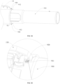
- the hub ratio is defined as the ratio of the maximum first diameter D1 formed by the fan blade support portion 253 to the second diameter D2 formed by the outermost edges of the fan blades 252.
- the hub ratio may also be defined as the ratio of the diameter formed by the tops of the fan blades 252 to the diameter formed by the roots of the fan blades 252 when the fan blades 252 rotate.
- the hub ratio is greater than or equal to 0.4 and less than or equal to 0.5.
- the first diameter D1 is about 47.2 mm and the hub ratio is about 0.46.
- the flow rate of the blower 10 is greater than or equal to 1000 CFM
- the fan assembly is an axial flow fan
- the hub ratio is greater than or equal to 0.4 and less than or equal to 0.5.
- Table one shows the flow rates, wind speeds, kinetic energy efficiencies, thrusts, and other parameters outputted by the blowers 10 with different hub ratios when the inner diameter D of the pipe assembly 260 is 105 mm and the motor 230 has different rotational speeds.
- the flow rate mentioned in the present application refers to the mass flow rate
- the wind speed refers to the wind speed at the outlet of the blower.
- the kinetic energy efficiency refers to (0.5*wind speed squared*mass flow rate)/fan loss.
- the maximum rotational speed of the motor does not need to increase to 35000 rpm to achieve an air volume greater than or equal to 1000 CFM.
- the rotational speed of the motor is relatively small so that the life of the bearings for positioning the motor can be extended, and the motor has a lower heat dissipation requirement, which is conducive to extending the life of the blower 10.
- the hub ratio is greater than 0.5, the efficiency of the whole machine is relatively high. Therefore, if the hub ratio is to be reduced to a range of 0.4 to 0.5, other technical solutions in this specification are needed to improve the efficiency of the whole machine.
- the maximum rotational speed of the motor is greater than or equal to 35000 rpm, the dynamic balance of the whole machine is affected, causing greater vibration of the whole machine and affecting the service life.
- the inner diameter D of the first pipe 220 of the blower 10 is not limited. That is to say, the blowers 10 with various inner diameters may all adopt the method of providing the through holes 243 on the first guide vane 242 to reduce the vibration and noise.
- the inner diameter D of the first pipe 220 is greater than or equal to 90 mm.
- the inner diameter D may be 95 mm, 100 mm, 105 mm, 1100 mm, 115 mm, or 125 mm.
- the blower 10 with a larger inner diameter D has a larger flow rate and makes greater noises. Therefore, applying the solution disclosed in the present application to the blower 10 with an inner diameter D greater than or equal to 90 mm can achieve more obvious vibration damping and noise reduction effects, but it does not mean that the technical solution of the present application is suitable for only the application to the blower 10 with an inner diameter D greater than or equal to 90 mm.
- the first pipe 220 includes the second guide vanes 222.
- the second guide vane 222 is engaged with the first guide vane 242.
- the second guide vanes 222 are disposed on the outer side of the conical pipe 223 to keep the conical pipe 223 stable.
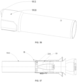
- a conical pipe 223a is formed inside a pipe assembly 260a, and the conical pipe 223a extends from a first end 2011a located on the front side of the pipe assembly 260a.
- the conical pipe 223a accommodates at least part of the motor 230, and the distance by which the conical pipe 223a extends from the first end 2011a is the fourth distance L4.
- the guide vane 282 includes a third end facing the fan blade 252 and a fourth end 2223 facing away from the fan blade.
- the distance from the fourth end 2223 to the first end is the fifth distance L5.
- the ratio L5/L4 of the fifth distance to the fourth distance is greater than or equal to 0 and less than or equal to 0.1.
- the inner diameter D of the pipe assembly 260 is generally greater than or equal to 90 mm to satisfy the requirement for outputting a large flow rate.
- the inner diameter D of the pipe assembly 260 is greater than or equal to 90 mm
- the air volume of the blower 10 is greater than or equal to 1000 CFM
- the operating rotational speed of the motor 230 is lower than 35000 rpm
- the fan assembly 250 is an axial flow fan.
- a wind tube 270 is mounted to the blow-suction structure 200.
- the wind tube 270 is mounted to the pipe assembly 260.
- the wind tube 270 may include various structures or forms to guide the flow direction and flow speed of the airflow when the airflow finally flows out.
- the user may mount different types of wind tubes 200 to satisfy different working conditions.
- the wind tube 270 may be a straight wind tube shown in FIG. 22 , a trumpet-shaped wind tube with an enlarged air outlet, or the like.
- the housing 100 is provided with a mounting portion 180 at the front side of the grip 150
- the handle 400 is provided with a mating portion 420
- the mating portion 420 is connected to the mounting portion 180.
- the mounting portion 180 is provided to improve the convenience of mounting the handle 400.
- a left mounting portion 113 is provided on the left housing 110
- a right mounting portion 123 is formed on the left housing 120. When the left housing 110 and the left housing 120 are buckled together, the left mounting portion 113 and the right mounting portion 123 together form the mounting portion 180.
- the shape of the handle 400 may also be configured to be an L shape or another irregular shape.
- the handle 400 is movably connected to the housing 100, and the handle 400 is rotatable relative to the housing 100 about a handle axis 410.
- the handle 400 can adaptively rotate about the handle axis 410 so that the posture of the handle 400 relative to the grip 150 is adjusted, thereby ensuring the comfort of the user holding the blower 10 with two hands.
- the handle axis 410 extends along the left and right direction, so the swing of the handle 400 and the adjustment of the posture of the handle 400 in the front and rear direction can be performed.
- FIG. 25 the handle 400 is movably connected to the housing 100, and the handle 400 is rotatable relative to the housing 100 about a handle axis 410.
- the angle of rotation of the handle 400 is ⁇ , and the angle of rotation ⁇ is greater than 10 degrees and less than or equal to 150 degrees, that is, the handle 400 is rotatable within a range of 10 degrees to 150 degrees. It is to be noted that the angle of rotation ⁇ is the maximum angle of rotation from the motor axis 231 of the blower 10 to the rear of the blower 10.
- the handle 400 has at least one lockable position.
- the handle 400 can be locked at a fixed position, thereby better satisfying the operating requirements of the user.
- the handle 400 may be configured to be lockable at one position, two positions, three positions, or any position within a rotatable angle range.
- the blower 10 further includes a mounting assembly 500, and the handle 400 is mounted on the housing 100 through the mounting assembly 500.
- the mounting assembly 500 enables the handle 400 to rotate about the handle axis 410 and enables the handle 400 to be locked at any position within a rotation angle range, thereby satisfying different usage requirements of the user.
- the user rotates the trigger 510 to unlock the handle 400.
- the handle 400 can be rotated so that the angle of the handle 400 can be adjusted.
- the trigger 510 is rotated in reverse so that the trigger 510 locks the handle 400 at the current position.
- the user rotates the trigger 510 to the unlocking position and keeps the trigger 510 at the unlocking position. Therefore, when the blower 10 is in use, the angle of the handle 400 can be automatically adjusted as the air discharge direction of the pipe assembly 260 changes.
- the user rotates the trigger 510 to the unlocking position and removes the fastener 530 from the rotary shaft 520. At this time, the handle 400 and the mounting assembly 500 can be removed from the housing 100, and the user holds the blower 10 only by the grip 150.
- a snap 460 is provided on one of the operating end 511 of the trigger 510 and the mating portion 420 of the handle 400, and a snap groove 5111 is provided on the other one of the operating end 511 of the trigger 510 and the mating portion 420 of the handle 400.
- the snap 460 and the snap groove 5111 can be snap-fitted together so that the positions of the trigger 510 and the handle 400 can be locked, thereby preventing the trigger 510 from being operated incorrectly.
- the snap 460 is provided on the mating portion 420 of the handle 400
- the snap groove 5111 is provided on the operating end 511 of the trigger 510.
- the snap groove 5111 may be provided on the mating portion 420 of the handle 400, and the snap 460 is provided on the operating end 511 of the trigger 510, as long as the snap 460 does not interfere with the rotation of the trigger 510.
- the handle 400 is configured to be an annular structure with a notch, and two ends of the annular structure are mating portions 420 of the handle 400. Two ends of the notch can clamp the left and right sides of the mounting portion 180, respectively.
- the working principle of the trigger 510 in this example is the same as that in the previous example.
- the maximum height of the entire blower 10 is H, where H is greater than or equal to 200 mm and less than or equal to 450 mm.
- H is greater than or equal to 200 mm and less than or equal to 450 mm.
- the maximum height of the blower 10 is set within a range of 200 mm to 450 mm so that the handle 400 has a suitable height. In this manner, it is convenient for the hand of the user to reach into the handle 400, and the dimension of the blower 10 in the height direction is not too large.
- the blower 10 further includes a belt coupling portion 170.
- a belt 800 is usually worn around the waist of the user, and the belt coupling portion 170 is used for mounting the entire blower 10 on the belt 800. Therefore, the belt 800 may be used for supporting the blower 10 with the help of the waist strength of the user, thereby reducing the fatigue of the hands of the user during use.
- the blower 10 here is a handheld blower that cannot be carried on the back of the user for use, rather than a backpack blower with a backpack function.
- the handheld blower has only the grip 150 that implements the main holding function and is located nearby.
- the handheld blower further has the handle 400 that implements the holding function together with the grip 150.
- the handle 400 may be understood as a second handle or an auxiliary handle.
- this example further provides the belt 800 to relieve the pressure on the grip 150.
- the belt 800 helps relieve the pressure on the grip 150 and the handle 400.
- the battery pack 130 of the blower 10 with the belt 800 is usually mounted along a blower axis 101, or the battery pack 130 is usually mounted in the extension region of the wind tube 270.
- the battery pack coupling portion 131 in this example is connected to the housing 100 instead of being provided outside the housing 100.
- the battery pack 130 is mounted on a backpack in the backpack blower.
- the belt coupling portion 170 is located behind the center of gravity G of the blower 10. It is to be noted that the center of gravity G represents the center of gravity of the blower 10 to which the battery pack 130 is mounted. In an example, the belt coupling portion 170 is disposed between an air inlet end of the pipe assembly 260 and the battery pack 130. In an example, the projection of the belt coupling portion 170 on the motor axis 231 is located within the range of the projection of the grip 150 on the motor axis 231. In an example, the belt coupling portion 170 is disposed between the grip 150 and the handle 400. In an example, the belt coupling portion 170 is disposed on the rear side of the center of gravity G.
- the belt coupling portion 170 is set within the preceding range so that the balance state of the blower 10 hung on the belt 800 is consistent with the balance state of the blower 10 held by the hand of the user.
- the blower 10 switches between a handheld state and a waist-hanging state, the user does not need to adjust the habits and skills of using the blower 10, thereby improving the convenience of operating the blower 10 and the user experience.
- the belt 800 includes a belt body 810 and a coupling member 820.
- the belt body 810 is wrapped around and fixed on the waist of the user, and the coupling member 820 is fixed on the belt body 810 and connected to the belt coupling portion 170.
- the belt body 810 includes a looped portion 811 and a shielding portion 812.
- the looped portion 811 is used for surrounding the waist of the user, and two ends of the looped portion 811 may be fixed through a snap connection, a strap connection, or the like.
- a first mounting portion 841 and a second mounting portion 842 are snap-fitted, thereby locking the belt 800.
- the shielding portion 812 is connected to the looped portion 811 and extends downward from the looped portion 811.
- the looped portion 811 has a first height M1 along the up and down direction
- the shielding portion 812 has a second height M2 along the up and down direction, where the second height M2 is greater than or equal to the first height M1.
- the shielding portion 812 has a first length M3 along the left and right direction, and the first length M3 is greater than or equal to the first height M1. In this manner, when the blower 10 is hooked on the belt 800, the shielding portion 812 can separate the blower 10 from the clothes of the user, thereby preventing the blower 10 from sucking the clothes of the user into the air inlet of the blower.
- the coupling member 820 includes a mounting belt 821 and a belt mounting portion 822.
- the coupling member 820 is fixed on the belt body 810.
- the belt mounting portion 822 is connected to the coupling member 820.
- the belt coupling portion 170 can be hooked on the coupling member 820.
- the coupling member 820 may be made of cloth so that the coupling member 820 can be easily connected to the belt body 810.
- the coupling member 820 may be made of metal material to ensure sufficient strength.
- the belt coupling portion 170 and the coupling member 820 are both configured to be hooks.
- one of the belt coupling portion 170 and the coupling member 820 may be configured to be a hook, and the other one of the belt coupling portion 170 and the coupling member 820 may be configured to be a hanging ring.
- the belt coupling portion 170 and the coupling member 820 may be a snap-fit structure, a strap structure, or the like.
- a penetration portion 8211 is provided on the coupling member 820
- the belt 800 further includes two lifting straps 830, the first ends of the two lifting straps 830 are both connected to the belt body 810, and the second ends of the two lifting straps 830 pass through the penetration portion 8211, intersect, and are connected to the belt body 810.
- the two lifting straps 830 are provided to lift the coupling member 820 so that the entire belt 800 can be prevented from being pulled downward excessively due to a larger force on the coupling member 820, thereby improving the user experience.
- the belt coupling portion 170 and the belt mounting portion 822 may each be an open hook, a completely enclosed hook, or a hook that is switchable between the open form and the completely enclosed form.
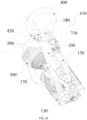
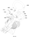
- the blower 10 further includes an illumination device 600 for increasing the brightness of the surrounding environment when the blower 10 is in operation so that the blower 10 can work well even in a dimly lit environment, thereby improving the user experience.
- the illumination device 600 includes a light assembly 610 and a switch assembly 620.
- the switch assembly 620 is used for controlling the working state of the light assembly 610.
- the light assembly 610 is connected to the housing 100 and disposed on the front side of the handle 400, thereby preventing the handle 400 from blocking the light of the light assembly 610. It is to be noted that the illumination device 600 may include only the light assembly 610 and does not include the switch assembly 620.
- the user may control the light assembly 610 through a device such as a mobile phone that is connected to the blower 10 via signals.
- the illumination device 600 may be provided with a light sensor.
- the light assembly 610 automatically lights up.
- the switch assembly 620 may be integrated with other switch structures of the blower 10.
- the light assembly 610 is disposed toward the front side of the blower 10, and the switch assembly 620 is disposed toward the top of the blower 10, thereby making it easier for the user to see and operate the switch assembly 620.
- the switch assembly 620 includes a button 621, a pivot shaft 624, an elastic member 622, and a first circuit board 623.
- the button 621 is pivotally connected to the housing 100 via the pivot shaft 624, and the axis of the pivot shaft 624 is a pivot axis 625.
- the first circuit board 623 is opposite to the button 621, and the first circuit board 623 is electrically connected to the light assembly 610.
- the elastic member 622 is disposed between the button 621 and the housing 100.
- the button 621 rotates about the pivot axis 625 and approaches the first circuit board 623, thereby triggering the electrical components on the first circuit board 623 and lighting the light assembly 610 up.
- the elastic member 622 resets the button 621.
- a mechanical switch is disposed on the first circuit board 623; and when the button 621 is reset, the mechanical switch is turned off, and the light assembly 610 is turned off accordingly.
- an electronic switch is disposed on the first circuit board 623; and when the button 621 is reset, the light assembly 610 is not turned off, and the user needs to press the button 621 again to turn off the light assembly 610.
- the light assembly 610 includes a second circuit board 611 electrically connected to the first circuit board 623.
- Light-emitting elements 614 are disposed on the second circuit board 611.
- the first circuit board 623 is triggered by the button 621, the second circuit board 611 turns on or off the light-emitting elements 614.
- the light-emitting element 614 may be a light-emitting diode (LED) lamp.
- the light assembly 610 further includes a light guide portion 612 and a light-transmissive portion 613.
- the light guide portion 612 is disposed on the front side of the second circuit board 611, and a light guide channel is disposed on the light guide portion 612.
- the light-emitting elements 614 at least partially extend into the light guide channel, thereby limiting the light direction of the light-emitting elements 614.
- the light-transmissive portion 613 covers the front side of the second circuit board 611, thereby protecting the second circuit board 611, the light-emitting elements 614, and the light guide portion 612 and ensuring that the light of the light-emitting elements 614 can propagate.
- the switch assembly 620 and the light assembly 610 are integrated, thereby making the appearance of the blower 10 simpler and more aesthetic.
- the integrated structure of the switch assembly 620 and the light assembly 610 is disposed toward the front side of the blower 10, thereby illuminating the working environment in front of the blower 10.
- the illumination device 600 includes a third circuit board 630 and a button 621 opposite to the third circuit board 630.
- the third circuit board 630 is provided with the light-emitting elements 614 and an electronic switch 640. In some examples, when the user presses the button 621, the button 621 triggers the electronic switch 640, and the third circuit board 630 causes the light-emitting elements 614 to light up.
- the electronic switch 640 is turned off, and the light-emitting elements 614 are turned off accordingly.
- the light-emitting elements 614 have at least two brightnesses.
- the light-emitting elements 614 emit light of the first brightness.
- the light-emitting elements 614 emit light of the second brightness.
- the light-emitting elements 614 are turned off.
- the illumination device 600 further includes a light guide portion 612 and a light-transmissive portion 613.
- the light guide portion 612 is disposed on the front side of the third circuit board 630.
- a light guide channel is formed on the light guide portion 612.
- At least some light-emitting elements 614 are located in the light guide channel.
- the light guide portion 612 guides the light emitted by the light-emitting elements 614.
- the light-transmissive portion 613 is disposed on the front side of the light guide portion 612.
- the light-transmissive portion 613 can protect the third circuit board 630, the light-emitting elements 614, and the light guide portion 612 and ensure that the light of the light-emitting elements 614 can propagate.
- the button 621 is movably connected to the light-transmissive portion 613 so that the light-transmissive portion 613 can support the button 621.
- the blower 10 has the blower axis 101, and the blower axis 101 is collinear with the axis of the pipe assembly 260.
- the included angle between the blower axis 101 and the ground is 25 degrees to 40 degrees.
- S1 is defined as the length of the projection of a line on the ground, where the line is a line between the frontmost end of the blower 10 and the farthest end that the illumination device 600 can illuminate on the ground when the blower 10 is in operation.
- S1 is greater than or equal to 1 m. In some examples, S1 is greater than or equal to 1.5 m. In some examples, S1 is greater than or equal to 2 m. It is to be understood that those skilled in the art may select the light assembly 610 with corresponding performance according to actual requirements for S1.
- S2 denotes the distance between the light assembly 610 and the frontmost end of the blower 10 along the direction of the blower axis 101
- S3 denotes the length of the blower 10 along the direction of the blower axis 101.
- S2/S3 is less than or equal to 0.8. By setting S2/S3 within this ratio range, while the light assembly 610 can be easily mounted, the light assembly 610 can be prevented from being positioned too far back, and the light assembly 610 can be prevented from being blocked by the pipe assembly 260 and creating a large shadow region on the ground, thereby improving the user experience.
- S2/S3 is less than or equal to 0.7. In some examples, S2/S3 is about 0.55 or 0.45.
- the communication board 715 is provided with a Bluetooth module, a Wi-Fi module, or the like.
- the control board 716 is a printed circuit board (PCB), and the control board 716 is electrically connected to the control assembly 720 of the blower 10.
- a light-emitting portion may be a liquid-crystal display (LCD) screen or an LED screen.
- the light-transmissive screen 712 is disposed on the front side of the light-emitting portion. The light-transmissive screen 712 can allow light from the light source 714 to pass through and can protect the light source 714.
- the mounting portion 90A may be provided on the wind tube 910, the elastic member 920 is mounted in the mounting portion 90A, the first end of the elastic member 920 abuts against the body 11, the second end of the elastic member 920 abuts against the groove bottom of the mounting portion 90A, and when the wind tube 910 is released from the body 11, the elastic member 920 is separated from the body 11 along with the wind tube 910.
- the first groove 932 is formed at an end of the mounting cover 930 facing the wind tube 910, and a protrusion is provided at the end of the wind tube 910 and can extend into a second groove 933, thereby achieving circumferential limitation between the wind tube 910 and the body 11.
- the unlocking member 940 When the wind tube 910 is to be removed, the unlocking member 940 is pushed in a direction facing the wind tube 910 so that the unlocking member 940 abuts against and pushes the wind tube 910, and the wind tube 910 moves away from the body 11.
- the wind tube 910 moves from the first section to the second section until the wind tube 910 is completely separated from the body 11, thereby achieving the removal of the wind tube 910 from the body 11.
- the elastic member 920 is elastically reset to reduce the force for pushing the unlocking member 940, thereby facilitating the operation.
- the body 11 and the wind tube 910 are connected through plugging and loosely mate with each other.
Landscapes
- Engineering & Computer Science (AREA)
- Mechanical Engineering (AREA)
- General Engineering & Computer Science (AREA)
- Physics & Mathematics (AREA)
- Geometry (AREA)
- Life Sciences & Earth Sciences (AREA)
- Environmental Sciences (AREA)
- Architecture (AREA)
- Civil Engineering (AREA)
- Structural Engineering (AREA)
- Structures Of Non-Positive Displacement Pumps (AREA)
Applications Claiming Priority (4)
| Application Number | Priority Date | Filing Date | Title |
|---|---|---|---|
| CN202210967982 | 2022-08-12 | ||
| CN202320947789.6U CN219862584U (zh) | 2023-04-24 | 2023-04-24 | 吹风机 |
| CN202310456589 | 2023-04-25 | ||
| PCT/CN2023/109482 WO2024032375A1 (zh) | 2022-08-12 | 2023-07-27 | 气流设备及手持式吹风机 |
Publications (2)
| Publication Number | Publication Date |
|---|---|
| EP4530405A1 true EP4530405A1 (de) | 2025-04-02 |
| EP4530405A4 EP4530405A4 (de) | 2025-09-03 |
Family
ID=89850784
Family Applications (1)
| Application Number | Title | Priority Date | Filing Date |
|---|---|---|---|
| EP23851597.7A Pending EP4530405A4 (de) | 2022-08-12 | 2023-07-27 | Luftstromvorrichtung und handhaartrockner |
Country Status (3)
| Country | Link |
|---|---|
| US (2) | US20250198424A1 (de) |
| EP (1) | EP4530405A4 (de) |
| WO (1) | WO2024032375A1 (de) |
Families Citing this family (1)
| Publication number | Priority date | Publication date | Assignee | Title |
|---|---|---|---|---|
| US20250129794A1 (en) * | 2023-10-23 | 2025-04-24 | Milwaukee Electric Tool Corporation | Blower / vac tools with improved fan blade noise |
Family Cites Families (12)
| Publication number | Priority date | Publication date | Assignee | Title |
|---|---|---|---|---|
| CN104074157B (zh) * | 2013-03-29 | 2016-02-10 | 南京德朔实业有限公司 | 手持式吹风机 |
| WO2015139720A1 (en) * | 2014-03-17 | 2015-09-24 | Husqvarna Ab | Blower layout |
| US20160298635A1 (en) * | 2014-09-15 | 2016-10-13 | Alare Technologies, Llc | Portable electrically powered debris blower apparatus |
| CN105442478B (zh) * | 2014-11-28 | 2017-12-01 | 苏州宝时得电动工具有限公司 | 吹风机 |
| CN106192837B (zh) * | 2015-05-25 | 2020-01-31 | 南京德朔实业有限公司 | 风机系统 |
| FR3044028B1 (fr) * | 2015-11-25 | 2017-11-17 | Pellenc Sa | Souffleur electroportatif a couple de reaction reduit. |
| CN205277933U (zh) * | 2015-12-11 | 2016-06-01 | 艾泰斯热系统研发(上海)有限公司 | 用于鼓风机的降噪蜗壳 |
| US10405707B2 (en) * | 2016-11-07 | 2019-09-10 | Nanjing Chervon Industry Co., Ltd. | Blower |
| DE202017106572U1 (de) * | 2017-10-30 | 2018-01-31 | Nanjing Chervon Industry Co., Ltd. | Bläser |
| CN113719478B (zh) * | 2020-05-25 | 2025-08-15 | 苏州宝时得电动工具有限公司 | 吹风机 |
| WO2022188888A1 (zh) * | 2021-03-12 | 2022-09-15 | 苏州宝时得电动工具有限公司 | 具有吹功能的园林工具 |
| CN215256988U (zh) * | 2021-06-09 | 2021-12-21 | 杭州顿力电器有限公司 | 一种低噪音出口导流器和带该出口导流器的通风机 |
-
2023
- 2023-07-27 EP EP23851597.7A patent/EP4530405A4/de active Pending
- 2023-07-27 WO PCT/CN2023/109482 patent/WO2024032375A1/zh not_active Ceased
-
2024
- 2024-12-18 US US18/986,195 patent/US20250198424A1/en active Pending
-
2025
- 2025-01-13 US US19/019,277 patent/US20250146508A1/en active Pending
Also Published As
| Publication number | Publication date |
|---|---|
| WO2024032375A1 (zh) | 2024-02-15 |
| US20250146508A1 (en) | 2025-05-08 |
| EP4530405A4 (de) | 2025-09-03 |
| US20250198424A1 (en) | 2025-06-19 |
Similar Documents
| Publication | Publication Date | Title |
|---|---|---|
| CN103216456B (zh) | 风扇 | |
| CA2800681C (en) | Device for blowing air by means of narrow slit nozzle assembly | |
| AU2016217668B2 (en) | A fan | |
| US20250146508A1 (en) | Blower | |
| JP5438078B2 (ja) | 送風機 | |
| EP2850325B1 (de) | Gebläse | |
| CA2976042A1 (en) | A fan assembly | |
| CN220365748U (zh) | 手持式吹风机 | |
| GB2484695A (en) | A fan assembly comprising a nozzle and inserts for directing air flow | |
| GB2535224A (en) | A fan | |
| CA2976029A1 (en) | A fan assembly | |
| GB2535223A (en) | A fan | |
| US12055158B2 (en) | Blower | |
| JP2025167469A (ja) | 着脱式送風装置、及び着脱式送風装置を備える衣服 | |
| KR20160144048A (ko) | 공기의 반사를 이용한 선풍기 |
Legal Events
| Date | Code | Title | Description |
|---|---|---|---|
| STAA | Information on the status of an ep patent application or granted ep patent |
Free format text: STATUS: THE INTERNATIONAL PUBLICATION HAS BEEN MADE |
|
| PUAI | Public reference made under article 153(3) epc to a published international application that has entered the european phase |
Free format text: ORIGINAL CODE: 0009012 |
|
| STAA | Information on the status of an ep patent application or granted ep patent |
Free format text: STATUS: REQUEST FOR EXAMINATION WAS MADE |
|
| 17P | Request for examination filed |
Effective date: 20241224 |
|
| AK | Designated contracting states |
Kind code of ref document: A1 Designated state(s): AL AT BE BG CH CY CZ DE DK EE ES FI FR GB GR HR HU IE IS IT LI LT LU LV MC ME MK MT NL NO PL PT RO RS SE SI SK SM TR |
|
| REG | Reference to a national code |
Ref country code: DE Ref legal event code: R079 Free format text: PREVIOUS MAIN CLASS: E01H0001080000 Ipc: F04D0025080000 |
|
| A4 | Supplementary search report drawn up and despatched |
Effective date: 20250801 |
|
| RIC1 | Information provided on ipc code assigned before grant |
Ipc: F04D 25/08 20060101AFI20250728BHEP Ipc: F04D 25/06 20060101ALI20250728BHEP Ipc: F04D 29/66 20060101ALI20250728BHEP Ipc: F04D 29/54 20060101ALI20250728BHEP |
|
| DAV | Request for validation of the european patent (deleted) | ||
| DAX | Request for extension of the european patent (deleted) |