EP4530373A1 - Emaillierung von aluminiummetallmatrixverbundwerkstoffen - Google Patents
Emaillierung von aluminiummetallmatrixverbundwerkstoffen Download PDFInfo
- Publication number
- EP4530373A1 EP4530373A1 EP24165890.5A EP24165890A EP4530373A1 EP 4530373 A1 EP4530373 A1 EP 4530373A1 EP 24165890 A EP24165890 A EP 24165890A EP 4530373 A1 EP4530373 A1 EP 4530373A1
- Authority
- EP
- European Patent Office
- Prior art keywords
- mmc
- cte
- glass
- coating
- pigment
- Prior art date
- Legal status (The legal status is an assumption and is not a legal conclusion. Google has not performed a legal analysis and makes no representation as to the accuracy of the status listed.)
- Pending
Links
Images


Classifications
-
- C—CHEMISTRY; METALLURGY
- C23—COATING METALLIC MATERIAL; COATING MATERIAL WITH METALLIC MATERIAL; CHEMICAL SURFACE TREATMENT; DIFFUSION TREATMENT OF METALLIC MATERIAL; COATING BY VACUUM EVAPORATION, BY SPUTTERING, BY ION IMPLANTATION OR BY CHEMICAL VAPOUR DEPOSITION, IN GENERAL; INHIBITING CORROSION OF METALLIC MATERIAL OR INCRUSTATION IN GENERAL
- C23D—ENAMELLING OF, OR APPLYING A VITREOUS LAYER TO, METALS
- C23D5/00—Coating with enamels or vitreous layers
-
- C—CHEMISTRY; METALLURGY
- C23—COATING METALLIC MATERIAL; COATING MATERIAL WITH METALLIC MATERIAL; CHEMICAL SURFACE TREATMENT; DIFFUSION TREATMENT OF METALLIC MATERIAL; COATING BY VACUUM EVAPORATION, BY SPUTTERING, BY ION IMPLANTATION OR BY CHEMICAL VAPOUR DEPOSITION, IN GENERAL; INHIBITING CORROSION OF METALLIC MATERIAL OR INCRUSTATION IN GENERAL
- C23D—ENAMELLING OF, OR APPLYING A VITREOUS LAYER TO, METALS
- C23D5/00—Coating with enamels or vitreous layers
- C23D5/02—Coating with enamels or vitreous layers by wet methods
-
- C—CHEMISTRY; METALLURGY
- C03—GLASS; MINERAL OR SLAG WOOL
- C03C—CHEMICAL COMPOSITION OF GLASSES, GLAZES OR VITREOUS ENAMELS; SURFACE TREATMENT OF GLASS; SURFACE TREATMENT OF FIBRES OR FILAMENTS MADE FROM GLASS, MINERALS OR SLAGS; JOINING GLASS TO GLASS OR OTHER MATERIALS
- C03C2207/00—Compositions specially applicable for the manufacture of vitreous enamels
- C03C2207/08—Compositions specially applicable for the manufacture of vitreous enamels for light metals
-
- C—CHEMISTRY; METALLURGY
- C03—GLASS; MINERAL OR SLAG WOOL
- C03C—CHEMICAL COMPOSITION OF GLASSES, GLAZES OR VITREOUS ENAMELS; SURFACE TREATMENT OF GLASS; SURFACE TREATMENT OF FIBRES OR FILAMENTS MADE FROM GLASS, MINERALS OR SLAGS; JOINING GLASS TO GLASS OR OTHER MATERIALS
- C03C2217/00—Coatings on glass
- C03C2217/70—Properties of coatings
- C03C2217/78—Coatings specially designed to be durable, e.g. scratch-resistant
Definitions
- an outer housing of the device e.g., a chassis, a case, a shell, etc.
- a method of forming an enameled coating on a structure made of a metal matrix composite (MMC) material includes providing a structure formed of the MMC material, the MMC material having a given coefficient of thermal expansion (CTE).
- An enamel mixture is formed to include a glass frit material and a pigment material, the material selected to yield a mixture with a substantially similar CTE.
- a surface of the MMC structure is coated with the enamel mixture, the structure then heated in order to melt and bond the enamel mixture. Following the heat treatment, the heated, coated MMC structure is cooled, thereby achieving a glass enameled coating with a color corresponding to the selected pigment.
- MMC structures e.g., housings used for electronic devices
- MMC metal matrix composite
- FIG. 1 a table is illustrated listing several material options for electronic housing applications. As shown, light grey squares represent favorable values, black squares represent less favored values, with mid-grey squares representing middling values.
- the considered material options include stainless steel, aluminum, magnesium, titanium, Al/SiC-55p MMC, and Al/Al 2 O 3 -50p MMC.
- the material characteristics considered are mass of the material (g/cc), stiffness, ductility, strength, hardness (relative to other materials), CTE, thermal conductivity, and cost (relative to other materials).
- MMC materials may be desirable to use in consumer devices, for example, to limit bendability (e.g., increasing rigidity) of the frame, while remaining lightweight and thin.
- a measure of the stiffness of a material is provided by Young's modulus, which is measured in Pascal (Pa) or Newtons/m 2 (in higher orders of magnitude, defined as GigaPascal-GPa or kilo-Newton/mm 2 ).
- Young's modulus on the order of 125 GPa provides a sufficiently stiff structural frame for device structures.
- Al/SiC MMC materials exhibit a density similar to aluminum, but with an increased stiffness.
- Al/SiC materials can be formed using many different processes, such as but not limited to, die-casting, extrusion, forging, thixoforming, power metallurgy, and the like.
- a structural element e.g., a frame
- steel is an option for such a structural frame, as it exhibits a high stiffness.
- steel also has a high density, which leads to high component mass.
- Aluminum is also an attractive material, with a density significantly lower than steel.
- aluminum exhibits a low relative stiffness, which may lead to bending. For instance, bending electronic components can lead to catastrophic damage, such that preventing bending is a main goal of the structure.
- Titanium has attractive properties for similar chassis applications, however titanium had a higher relative cost.
- Stainless steel has high mass, which may be less attractive for small, portable devices.
- MMCs provide a favorable combination of physical characteristics while being easily tailored for specific applications.
- Al/SiC has been used to illustrate results of the disclosed techniques and applications. As shown, Al/SiC has a relatively low mass, providing a desirable lightweight frame. Stiffness is relatively high, as is thermal conductivity, while CTE is relatively low. Despite challenges with relative ductility and strength, Al/SiC remains an attractive candidate material for such devices.
- Al 2 O 3 material is less expensive than Al, which can reduce blending costs for MMCs.
- SiC particles are more expensive than Al, which can add to blended costs for MMCs.
- the favorable properties may make such materials a good choice for some applications.
- a metal matrix composite is a material with at least two constituent parts-one being a metal and the other being a ceramic or organic compound (and/or a different type of metal).
- MMCs are made by dispersing a reinforcing material into a metal matrix.
- carbon fiber is used as the reinforcing material with an aluminum matrix, creating composites exhibiting low density and high strength.
- a MMC is made of aluminum (Al) impregnated with ceramic particles, such as silicon carbide, to form Al/SiC MMCs.
- aluminum oxide may be used to form Al/Al 2 O 3 MMCs.
- MMCs can be tailored for a desired density, stiffness, ductility (elongation), strength, machinability, and/or thermal behavior.
- MMC materials may be used with the disclosed techniques, and the scope of the disclosure is not limited to any specific material, or class of materials.
- the metal matrix may be reinforced with any acceptable type of carbon fiber, ceramic fiber, or ceramic, where the type (and percentage) of reinforcement selected will result in an MMC with specific characteristics in terms of stiffness and strength.
- MMC materials are described with a material content that includes a first metal material (e.g., aluminum, steel, titanium, magnesium alloys), and a second reinforcement material (e.g., SiC, Al 2 O 4 and/or B 4 C) present in a second amount (e.g., up to approximately 55%).
- a first metal material e.g., aluminum, steel, titanium, magnesium alloys
- a second reinforcement material e.g., SiC, Al 2 O 4 and/or B 4 C
- FIGS. 2A to 2E illustrate some challenges in producing anodized structures.
- FIGS. 2A to 2E illustrate images representative of substrates (e.g., housings) of a variety of composition with anodization. However, each represents discontinuities in the application anodization.
- the figures represent an aluminum substrate 6061 Al; and MMC substrates Al/SiC-55p; Al/Al 2 O 3 -50p; Al/Al 2 O 3 -30p; and Al/Al 2 O 3 -25p; respectively.
- anodizing a housing made of substantially pure Al yields a smooth red surface (e.g., represented in FIG. 2A ).
- each of the MMC substrates develop a matte (e.g., rough, broken) finish.
- the anodized layer grows at locations on the surface substantially exposing Al, but does not at location with other particle types.
- the Al/SiC example of FIG. 2B does not maintain color (e.g., turns gray), and the MMC substrates that include Al/Al 2 O 3 do accept the color, but the color is less vibrant with increasing reinforcement concentration (which may be needed for durability and coating fidelity).
- a challenge in enameling MMC materials is that the coefficient of thermal expansion (CTE) of the coating material (e.g., glass) should substantially match the CTE of the MMC substrate material. If a significant difference exists between CTEs of the coating materials and the MMC substrate materials, the coating tends to separate from the MMC substrate during cooling from the heat treatment, as contraction of the materials differs. To better match CTE between materials, two or more constituents (provided as frits) can be batched together to create an enamel mixture or slurry with a CTE that is equal to or substantially similar to that of the MMC substrate material.
- CTE coefficient of thermal expansion
- the disclosed process can yield a structure with one or more colors, while enjoying the mechanical and thermal benefits of a MMC structure.
- glass enameling can provide enhanced coloring and coating effects in comparison to other techniques (e.g., Anodization).
- Anodization For consumer applications such as electronic mobile devices, the ability to color parts of the structure in a wide range of colors can be appealing to manufacturers and customers.
- Chassis for cell phones are currently made from aluminum (Al), however MMCs offer an opportunity for creating lighter, thinner, and stronger chassis.
- Al aluminum
- MMCs offer an opportunity for creating lighter, thinner, and stronger chassis.
- One challenge to MMCs for this application is that, even as Al can be readily anodized to create products in many colors, anodization is not as effective for MMCs materials.
- the MMC housings exhibit a combination of the desired properties for a personal device frame, including low mass (similar to aluminum) and high stiffness (similar to steel).
- MMC materials with aluminum as a major component, reinforced with SiC or Al 2 O 3 reinforcement content offers challenges to maintaining a consistent and appealing coating. While some example MMC material housings are illustrated and described as a single rectangle, various other geometries and/or topologies for MMC material structural elements may be utilized for application seeking to increase the rigidity and/or strength of the structure (useful for industrial or military applications, for example).
- FIG. 3A illustrates an example glass enameling technique applied to MMC substrates, as disclosed herein.
- an enamel mixture/slurry of glass powder 12 applied to a surface of a MMC substrate 10A.
- the slurry 12 includes a mixture consisting of one or more frits, such as pigment frits 14 and glass frits 16.
- the MMC substrate 10A is coated with the slurry 12 and heated by thermal treatment 18 to melt the frit(s), creating a glass coating 20 on MMC substrate 10B.
- two material types are shown in the example of FIG. 3A , three, four, five, six, seven, eight, nine, ten or more material types may be included in the slurry (e.g., as frits).
- the slurry 12 can be designed to produce a clear or translucent coating after firing (e.g., thermal treatment 18).
- the slurry 12 may include glass material frits 16, or a combination of glass materials, such that a resulting glass coating 20 is substantially clear, while providing a protective layer over the MMC substrate 10B.
- pigment frits 14 can be added to the slurry 12, thereby producing a colored coating.
- an amount of red pigment e.g., approximately 10% by weight of the slurry was added to the mixture as pigment frits 14, thereby creating a red glass coating 20.
- two or more different glass frits 16 without pigment are used (e.g., to form the glass material).
- a benefit of using two or more different glass frits is the ability to select glass frits with different CTE values that, collectively, approximate a desired CTE and firing temperature for use with a selected substrate. For instance, some frits may be are sold with a description of their CTE and firing temperature (with values shown in example FIG. 4A ). However, each frit may have different chemical compositions to achieve these properties. Thus, combining frits with different properties may yield the desired effect, including incorporation of a pigment, as disclosed herein.
- delamination can occur during cooling if the materials used in the enamel mixture have a CTE that does not substantially match a CTE of the MMC substrate.
- CTE of the mixture of frits can be tailored by mixing together one or more frits, even using different frits with different CTEs.
- the coated MMC is fired at a specific temperature designed to melt the frits, thereby allowing the coating materials to adhere to the MMC substrate.
- This temperature is selected to be below the solidus temperature of the MMC substrate material (for example, an alloy) to avoid melting the MMC material.
- MMC substrates formed of a SiC-reinforced Al alloy high Si content in the alloy sets the solidus temperature at about 577 degrees C, which may be lower than that of typical Al alloys. Therefore, the frits must be chosen to create an enamel mixture with a firing temperature below that the solidus temperature of the SiC-reinforced Al alloy.
- a coating can be applied to one or more surfaces of the structure treated with MMC enameling techniques by 1) applying an enamel mixture or slurry (e.g., containing glass frit and pigment) to a surface of the structure, and 2) heat treating (e.g., firing) the structure in a furnace.
- an enamel mixture or slurry e.g., containing glass frit and pigment
- FIG. 4A provides a table for an example enamel mixture composition for glass enameling of a MMC substrate, as disclosed herein.
- a MMC substrate is provided with a content of SiC/Al of approximately 55%.
- the MMC substrate has a CTE of approximately 11, and a maximum temperature of approximately 577 degrees C.
- An enamel mixture comprises of frits A and B, with a concentration of approximately 33% and 67%, respectively.
- Frit A corresponds to a CTE of approximately 9.3 and a firing temperature of approximately 500
- frit B corresponds to a CTE of approximately 12.5 and a firing temperature of approximately 560.
- the resulting CTE is approximately 11.4 and a firing temperature of approximately 540.
- the frit mixture CTE is within a threshold difference (less than 5%, but can be less than 1%, 10%, 15%, 20%, or any other amount to achieve a desired result). Additionally, firing temperature of the frit mixture is below the maximum temperature of the MMC substrate.
- FIGS. 4B and 4C show examples of MMC housings 30A and 30B with enameled coatings, as disclosed herein.
- the MMC housings are each Al alloys with SiC components.
- the MMC housing 30A of FIG. 4A has a top portion 32A and a lower portion 34A, the top portion 32A being treated with a glass enamel mixture with 10% pigment, and the lower portion 34A without pigment.
- the MMC housing 30B of FIG. 4C has a top portion 32B and a lower portion 34B, the top portion 32B being treated with a glass enamel mixture with 10% pigment, and the lower portion 34B without pigment.
- the difference in finishes between FIGS. 4B and 4C stems from thermal treatment times.
- the MMC housing 30A was treated for a relatively short amount of time (e.g., five minutes) in a particular treatment environment (e.g., ambient air).
- the MMC housing 30B was treated for a relatively longer amount of time (e.g., 20 minutes) in a similar treatment environment.
- the relatively dark appearance of the top portion 32B of the MMC housing 30B represents deeper coloring versus the top portion 32A of the MMC housing 30A. This is a result of the extended thermal treatment time for MMC housing 30B, which allowed more time for melting of the enamel mixture, creating a richer color.
- FIG. 5A illustrates a MMC substrate with an exposed surface.
- FIG. 5B illustrates the MMC substrate following application of an enamel mixture (including glass frits and pigment frits, for example) on the MMC substrate and thermal treatment.
- an enamel mixture including glass frits and pigment frits, for example
- constituent materials for the enamel mixture are selected such that the CTE of the combination of frits is a substantial match to the CTE of the MMC substrate. Accordingly, the finished glass coating is less subject to delamination during cooling in comparison to other techniques.
- the MMC substrate shown in FIGS. 5A and 5B can be used for consumer applications, such as mobile electronic devices.
- consumer applications such as mobile electronic devices.
- the capability to color parts of the device housing in a wide range of colors is an appealing prospect for manufacturers and consumers.
- the disclosed techniques and coatings can be used for consumer applications in which the aesthetics of the parts are an important feature.
- the glass enameling applied to the MMC housing provides a wear-resistant and/or corrosion-resistant coating, in addition to providing color.
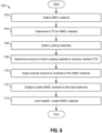
- FIG. 6 is a flowchart representative of an example method 100 for enamel coating a MMC material, in accordance with this disclosure.
- a MMC material is selected (e.g., AlSiC-55p).
- CTE for the selected MMC material is determined.
- coating materials for an enamel mixture are selected.
- the type of material e.g., glass, pigment, etc.
- the glass frits alone produce a clear or translucent coating after the thermal treatment.
- the coating materials (and enamel mixture) are selected to ensure that the firing temperature is below the solidus temperature of the MMC material to avoid damage to the MMC substrate.
- an amount of each of the coating materials is determined.
- the CTE for the enamel mixture should be within a threshold range of the CTE for the selected MMC material.
- the amount of the coating materials e.g., two or more, provided as multiple frits
- the enamel mixture is applied to one or more surfaces of the MMC material.
- the coated MMC material is subjected to a thermal treatment to melt the enamel mixture.
- the temperature, length of treatment time, and/or treatment environmental conditions can be determined, to achieve a desired result.
- the coated MMC material can be heated at temperatures up to 600 degrees C between five and 20 minutes, or longer, in an ambient air environment. For instance, some enameled coatings benefit from longer heating times, thereby ensuring complete or nearly complete melting of the glass frits, creating better coloring.
- the coated MMC material is cooled, thereby providing a durable, colored coating for the underlying material.
- the coated MMC material is subjected to one or more additional surface treatments to enhance the protective or aesthetic properties of the finished product.
- a method of forming an enameled coating on a structure made of a metal matrix composite (MMC) material including providing a structure formed of a MMC material; forming an enamel mixture having one or more glass materials and zero or more pigment materials; coating the enamel mixture on a surface of the MMC structure; heating the coated MMC structure to melt the enamel mixture; and cooling the heated, coated MMC structure to achieve a glass enameled coating.
- MMC metal matrix composite
- a MMC material of the MMC structure includes a first CTE.
- the glass material comprises a second CTE.
- the pigment material comprises a third CTE.
- the method further includes selecting a ratio of the glass material to the pigment material to result in the enamel mixture having the first CTE. In examples, the method further includes selecting the MMC material from Al/SiC or Al/Al 2 O 3 .
- forming the enamel mixture includes mixing glass frits of the glass material and pigment frits of the pigment material with a liquid media.
- a method of forming an enameled coating on a structure made of a metal matrix composite (MMC) material including providing a structure formed of a MMC structure with a MMC material with a first coefficient of thermal expansion (CTE); forming an enamel mixture with a second CTE similar to the first CTE; coating the enamel mixture on a surface of the MMC structure; heating the coated MMC structure to melt the enamel mixture; and cooling the heated, coated MMC structure to achieve a glass enameled coating.
- MMC metal matrix composite
- a value of the second CTE is within 10% of a value of the first CTE.
- the enamel mixture comprises a glass material with a third CTE and a pigment material with a fourth CTE, the second CTE being different from the third and fourth CTE.
- the enamel mixture comprises approximately two thirds of the glass material and one third of the pigment material.
- the heating is performed in a furnace at a temperature of greater than 500 degrees C.
- the method further includes selecting the MMC material from Al/SiC or Al/Al 2 O 3 .
- a structure with an enameled coating includes a structural frame formed of an MMC material containing a metal and a ceramic or organic compound; and an enameled coating on a surface of the MMC material, the enameled coating containing a coating material and a pigment material.
- the coating material is a glass or ceramic material and the pigment material is a colored dye.
- the MMC material has a first CTE, the enameled coating having a CTE substantially similar to the first CTE.
- the MMC material comprises Al/SiC or Al/Al 2 O 3 .
- the Young's modulus value of the MMC material is greater than 125 GPa.
- Implementations as described herein may relate to the following: A method of forming an enameled coating on a structure made of a metal matrix composite (MMC) material.
- the method includes providing a structure formed of the MMC material, the MMC material having a given coefficient of thermal expansion (CTE).
- An enamel mixture is formed to include a glass material and a pigment material, the material selected to yield a mixture with a substantially similar CTE.
- a surface of the MMC structure is coated with the enamel mixture, the structure then heated in order to melt the enamel mixture. Following the heat treatment, the heated, coated MMC structure is cooled, thereby achieving a glass enameled coating with a color corresponding to the selected pigment.
Landscapes
- Chemical & Material Sciences (AREA)
- Engineering & Computer Science (AREA)
- Materials Engineering (AREA)
- Mechanical Engineering (AREA)
- Metallurgy (AREA)
- Organic Chemistry (AREA)
- Glass Compositions (AREA)
Applications Claiming Priority (1)
| Application Number | Priority Date | Filing Date | Title |
|---|---|---|---|
| US18/478,578 US20250333848A1 (en) | 2023-09-29 | 2023-09-29 | Glass enameling of aluminum metal matrix composites |
Publications (1)
| Publication Number | Publication Date |
|---|---|
| EP4530373A1 true EP4530373A1 (de) | 2025-04-02 |
Family
ID=90571787
Family Applications (1)
| Application Number | Title | Priority Date | Filing Date |
|---|---|---|---|
| EP24165890.5A Pending EP4530373A1 (de) | 2023-09-29 | 2024-03-25 | Emaillierung von aluminiummetallmatrixverbundwerkstoffen |
Country Status (4)
| Country | Link |
|---|---|
| US (1) | US20250333848A1 (de) |
| EP (1) | EP4530373A1 (de) |
| JP (1) | JP7765510B2 (de) |
| CN (1) | CN119736629A (de) |
Citations (3)
| Publication number | Priority date | Publication date | Assignee | Title |
|---|---|---|---|---|
| US3368712A (en) * | 1960-07-05 | 1968-02-13 | Ritter Pfaudler Corp | Semicrystalline glass and method of applying the same to metallic bases |
| US20170260617A1 (en) * | 2016-03-09 | 2017-09-14 | Sohome Houseware (Nanjing) Co., Ltd. | Manufacturing process of heat-resisting glass or enamel coating on a thermally insulated container chamber |
| US20210188699A1 (en) * | 2018-05-12 | 2021-06-24 | Zhejiang University | Metal anticorrosive coating, preparation method therefor, and use therefor |
Family Cites Families (5)
| Publication number | Priority date | Publication date | Assignee | Title |
|---|---|---|---|---|
| JPS63247380A (ja) * | 1987-04-02 | 1988-10-14 | Nisshin Steel Co Ltd | 透明着色ホ−ロ−アルミ被覆鋼板およびその製造法 |
| JP2977774B2 (ja) * | 1996-02-28 | 1999-11-15 | 村田ボーリング技研株式会社 | ガラス被膜ロ−ル、高分子フィルム表面印刷受容性用処理ロ−ル及び高分子フィルムの表面を印刷受容性にする方法 |
| JP5822766B2 (ja) * | 2012-03-21 | 2015-11-24 | 株式会社日立製作所 | 金属基複合材料及びその製造方法 |
| US20160373154A1 (en) * | 2015-06-16 | 2016-12-22 | Ii-Vi Incorporated | Electronic Device Housing Utilizing A Metal Matrix Composite |
| CN114437616B (zh) | 2022-03-17 | 2022-11-08 | 惠州市日大实业有限公司 | 抗指纹高固低粘耐磨仿陶瓷光固化涂料及其制备方法 |
-
2023
- 2023-09-29 US US18/478,578 patent/US20250333848A1/en active Pending
-
2024
- 2024-01-09 CN CN202410035898.XA patent/CN119736629A/zh active Pending
- 2024-01-18 JP JP2024005799A patent/JP7765510B2/ja active Active
- 2024-03-25 EP EP24165890.5A patent/EP4530373A1/de active Pending
Patent Citations (3)
| Publication number | Priority date | Publication date | Assignee | Title |
|---|---|---|---|---|
| US3368712A (en) * | 1960-07-05 | 1968-02-13 | Ritter Pfaudler Corp | Semicrystalline glass and method of applying the same to metallic bases |
| US20170260617A1 (en) * | 2016-03-09 | 2017-09-14 | Sohome Houseware (Nanjing) Co., Ltd. | Manufacturing process of heat-resisting glass or enamel coating on a thermally insulated container chamber |
| US20210188699A1 (en) * | 2018-05-12 | 2021-06-24 | Zhejiang University | Metal anticorrosive coating, preparation method therefor, and use therefor |
Also Published As
| Publication number | Publication date |
|---|---|
| CN119736629A (zh) | 2025-04-01 |
| JP2025060362A (ja) | 2025-04-10 |
| JP7765510B2 (ja) | 2025-11-06 |
| US20250333848A1 (en) | 2025-10-30 |
Similar Documents
| Publication | Publication Date | Title |
|---|---|---|
| TWI606122B (zh) | 具有高強度及外表吸引力之鋁合金 | |
| Alam et al. | Review on Aluminium and Its Alloys for automotive applications | |
| US9120933B2 (en) | White hard decorative member | |
| US9400524B2 (en) | Metal ceramic chassis for portable devices | |
| JP5979928B2 (ja) | 硬質装飾部材 | |
| JP2021059784A (ja) | 高い強度及び美的訴求力を有するアルミニウム合金 | |
| US9452570B2 (en) | Information handling system ceramic chassis | |
| JP6084286B2 (ja) | グレー色調層を有する硬質装飾部材 | |
| JP5979927B2 (ja) | 金色硬質装飾部材 | |
| US20180309469A1 (en) | Electronic Device Housing Utilizing A Metal Matrix Composite | |
| EP4530373A1 (de) | Emaillierung von aluminiummetallmatrixverbundwerkstoffen | |
| US9920401B2 (en) | Aluminum base alloy with high thermal conductivity for die casting | |
| Dai et al. | Effect of thermal conductivity on micro-arc oxidation coatings | |
| Kochmańska et al. | Cyclic oxidation of slurry silicide-aluminide coatings formed on Ti-6Al-4V alloy | |
| Zhenzhen et al. | Effect of Cu content on the microstructures and wear performance of Al–Si–Cu–Ni–Mg alloy based SiC reinforcement composites | |
| EP1484428A1 (de) | Verfahren zur anodischen Oxidation von Filme aus einer Aluminiumlegierung | |
| Sheikh et al. | Influence of cenosphere reinforcement on microstructure, microhardness, and corrosion behavior of Al5052 alloy matrix composite produced by compo casting method | |
| Kang et al. | Development and Characterization of Blue-Colored Mg2Si-Based Recycled Alloys Using Scrap Light Metals | |
| US20150218725A1 (en) | Metal material having protective coating and method for manufacturing the same | |
| CN106498391A (zh) | 氧化着色的多层膜结构 | |
| CN101564916A (zh) | 表面具有锡锑铝巴氏合金涂层的镁合金构件及其制作方法 | |
| JP2005015819A (ja) | 母材表面がメッキ処理された成形品の表面処理方法 | |
| KR20090103281A (ko) | 원적외선 발생소자 | |
| JP2001303269A (ja) | 金属成形品の表面処理 | |
| HUP0302374A2 (hu) | Alumíniumötvözet alumíniumszalag előállításához |
Legal Events
| Date | Code | Title | Description |
|---|---|---|---|
| PUAI | Public reference made under article 153(3) epc to a published international application that has entered the european phase |
Free format text: ORIGINAL CODE: 0009012 |
|
| STAA | Information on the status of an ep patent application or granted ep patent |
Free format text: STATUS: REQUEST FOR EXAMINATION WAS MADE |
|
| 17P | Request for examination filed |
Effective date: 20240325 |
|
| AK | Designated contracting states |
Kind code of ref document: A1 Designated state(s): AL AT BE BG CH CY CZ DE DK EE ES FI FR GB GR HR HU IE IS IT LI LT LU LV MC ME MK MT NL NO PL PT RO RS SE SI SK SM TR |
|
| P01 | Opt-out of the competence of the unified patent court (upc) registered |
Free format text: CASE NUMBER: APP_16417/2025 Effective date: 20250404 |