EP4530263A1 - Schmelzgefäss zum schmelzen von glas und verfahren zur herstellung einer glasschmelze - Google Patents
Schmelzgefäss zum schmelzen von glas und verfahren zur herstellung einer glasschmelze Download PDFInfo
- Publication number
- EP4530263A1 EP4530263A1 EP23200790.6A EP23200790A EP4530263A1 EP 4530263 A1 EP4530263 A1 EP 4530263A1 EP 23200790 A EP23200790 A EP 23200790A EP 4530263 A1 EP4530263 A1 EP 4530263A1
- Authority
- EP
- European Patent Office
- Prior art keywords
- melting
- section
- glass melt
- bottom wall
- hours
- Prior art date
- Legal status (The legal status is an assumption and is not a legal conclusion. Google has not performed a legal analysis and makes no representation as to the accuracy of the status listed.)
- Granted
Links
Images


Classifications
-
- C—CHEMISTRY; METALLURGY
- C03—GLASS; MINERAL OR SLAG WOOL
- C03B—MANUFACTURE, SHAPING, OR SUPPLEMENTARY PROCESSES
- C03B5/00—Melting in furnaces; Furnaces so far as specially adapted for glass manufacture
- C03B5/16—Special features of the melting process; Auxiliary means specially adapted for glass-melting furnaces
- C03B5/18—Stirring devices; Homogenisation
- C03B5/183—Stirring devices; Homogenisation using thermal means, e.g. for creating convection currents
- C03B5/185—Electric means
-
- C—CHEMISTRY; METALLURGY
- C03—GLASS; MINERAL OR SLAG WOOL
- C03B—MANUFACTURE, SHAPING, OR SUPPLEMENTARY PROCESSES
- C03B5/00—Melting in furnaces; Furnaces so far as specially adapted for glass manufacture
- C03B5/02—Melting in furnaces; Furnaces so far as specially adapted for glass manufacture in electric furnaces, e.g. by dielectric heating
- C03B5/027—Melting in furnaces; Furnaces so far as specially adapted for glass manufacture in electric furnaces, e.g. by dielectric heating by passing an electric current between electrodes immersed in the glass bath, i.e. by direct resistance heating
- C03B5/03—Tank furnaces
Definitions
- This disclosure relates to a melting vessel for glass melting, and a method for making a glass melt.
- the production of glass has a high carbon footprint due to the amount of energy required for the melting and fining processes. This is particularly the case for heating by gas burners which use natural gas.
- a reduction of the carbon footprint is possible if, instead, an electric resistance heating is used which is provided with power from renewable energy sources like wind power, waterpower, or solar panels.
- the same power sources may also be used to produce hydrogen by electrolysis which then can be used to feed the gas burners. While the latter requires less changes to an existing glass production facility with a gas burner heating, the intermediate step of electrolysis is associated with a considerable energy loss. Hence, a direct use of the electrical power is more desirable.
- glass compositions There are various kinds of glass compositions. Some glass compositions are relatively easy to manufacture in good quality, others require sophisticated equipment and/or extremely well-balanced production processes. Generally, the glass compositions used to make drinking glasses and bottles, ordinary windowpanes, and other construction glass products, e.g., glass wool used for insulation, are relatively easy to manufacture in good quality because the glass used for these products has rather low melting temperatures and a steep viscosity-temperature curve. Additionally, quality criteria of these manufactured products are not very stringent. For example, drinking glasses and construction glass products may contain an occasional bubble and/or solid inclusions, and variations in shape and dimension which are tolerable for the said purposes. These glass products may contain impurities to a certain extent because their use does not require defined light transmission properties, or stringent purity regulations.
- the types of glass compositions used for many mass products have low melting temperatures because of significant amounts of alkali metal oxides and alkaline earth metal oxides.
- the respective glass melting facilities achieve very high throughput, often more than 200 tons of glass per day, or even 400 tons per day. Naturally, the amount of energy needed for making 200 tons of low melting glass is significantly lower than for a higher melting glass.
- high-quality glasses are used to make products that may not have the occasional bubble and must meet stringent criteria in terms of shape, dimensional variations, and purity (both chemical and optical). Many of these glasses are rather difficult to manufacture not only because of the stringent criteria but also because of high melting temperatures. High melting temperatures may be necessary to achieve melt viscosities sufficient for homogenization and removal of bubbles from the melt. Examples of high-quality glass products include pharmaceutical containers and glass tubes used for making such containers.
- CN 107686226 A discloses a melting kiln for borosilicate glass comprising a cold-top melting furnace which is exclusively heated by electric means and a clarifier for, respectively heating and refining a glass melt.
- a liquid flow hole is provided at the bottom of the cold-top melting furnace, wherein an outlet end of the flow hole communicates with a lower end of a vertically arranged rising channel through which the molten glass passes. The upper end of the rising channel communicates with and feeds the molten glass into an inlet of the clarifier.
- the upper part of the cold-top melting furnace is provided with a feeding port for supplying borosilicate batch materials.
- the inner side of the cold-top melting furnace is provided with multiple kiln electrodes for heating by electric means.
- the interior of the clarifier is provided with a plurality of electrodes and a plurality of burners.
- all burners may be arranged in the upper part of the clarifier.
- a bubbling device may be disposed on the bottom brick of the clarifier to assist and improve refining the glass melt.
- this disclosure relates to a melting vessel (101) for glass melting comprising
- this disclosure relates to a melting vessel (101) for glass melting comprising
- this disclosure relates to a melting vessel (101) for glass melting comprising
- the melting vessel according to this disclosure comprises a melting section (101a) and a conditioning section (101b) which is designed to provide for continuous melting of a glass batch, i.e., a batch of raw materials which upon melting form a glass melt in the melting section.
- the melting vessel provides for obtaining a homogeneous glass melt in the conditioning section which may be processed further in additional parts downstream of the disclosed melting vessel.
- the melting vessel according to this disclosure is energy efficient with respect to melting the batch of raw materials to form a glass melt and to obtain a homogeneous glass melt.
- this disclosure relates to a method for making a glass melt (120), comprising the steps of
- this disclosure relates to a method for making a glass melt (120), comprising the steps of
- the method for making a glass melt according to this disclosure is related to the melting vessel for glass melting and may be carried out using the melting vessel for glass melting according to this disclosure. Both the method for making a glass melt and the melting vessel according to this disclosure provide for obtaining a homogenous glass melt which is essentially free of "relicts", such as, e.g., crystals of portions of the raw material. The method and the melting vessel provide for convection currents in the melting section which create a distinct temperature layer and density layer of the molten part in said melting section which is different from the conditioning section.
- Both the method and the melting vessel may be operated exclusively using two or more heating circuits, optionally in the melting section, which rely on renewable energy sources. Nonetheless, the initial step of melting a batch of raw materials into a glass melt in the melting section may be assisted by fuel burners relying on fossil fuels or may be alternatively assisted by oxyfuel burners relying on oxygen and hydrogen. In subsequent process steps, the method may be performed by continuous electric heating.
- a "glass melt” is a volume of a batch of glass raw materials that has a viscosity of less than 10 7.6 dPas. Such a viscosity can be measured using the fiber elongation method, e.g., as described in DIN ISO 7884-6:1998-02, where the elongation speed of a fiber with a defined diameter is determined with different weights at different temperatures.
- the temperature at which the glass melt has a viscosity of 10 2 dPas is herein called “temperature T2".
- the temperature at which the glass melt has a viscosity of 10 4 dPas is herein called “temperature T4".
- Temperature T2 is less than 1,500 °C for glass compositions with high contents of alkali metal oxides or alkaline earth metal oxides, such as soda lime glass and other glass compositions. These viscosities can be measured using a rotational viscosimeter, e.g. as described in DIN ISO 7884-2:1998-2.
- t is the temperature under consideration.
- A, B and t 0 are the so-called VFT constants that are specific for each glass composition.
- Dwell time is the time that a given portion of the glass melt spends in a part of the apparatus, e.g., the melting vessel before being withdrawn from the melting vessel, or the melting section (101a) of the melting vessel (101), or the conditioning section (101b) of the melting vessel (101). Dwell time can be measured using so-called tracers, i.e., components that are added to the glass melt so that they can be detected in the product, allowing conclusions as to the time spent in the melting vessel. Examples of tracer compounds are Ca, Sr and Y.
- the "average dwell time” is defined as: melting vessel volume m 3 melting vessel throughput m 3 h
- the "minimum dwell time” describes the shortest time that an individualized portion of the glass melt passes through a certain part of the apparatus.
- the “minimum dwell time” can also be measured using so-called tracers, for example by adding tracers to the batch of raw materials when fed into the melting vessel and by measuring the time it takes to detect said tracers upon leaving in the conditioning section (101b) of the melting vessel (101).
- the "minimum dwell time" of the glass melt in the conditioning section (101b) of the melting vessel (101) can be measured as the time difference between detecting tracers in the glass melt when passing the opening (105) and detecting said tracers at the second bottom wall (102b) of the conditioning section (101b).
- the melting vessel (101) comprises a melting section (101a) and a conditioning section (101b), wherein the conditioning section (101b) is below the melting section (101a).
- the melting section and the conditioning section shall be understood as geometrical bodies whose inner dimensions and geometrical properties are described in the following two paragraphs.
- the terminology "wall”, i.e., the first bottom wall (102a), the first wall (103a), the second bottom wall (102b) and the second wall (103b), shall be understood as a geometrical boundary.
- the melting section (101a) shall be understood as a geometrical body with a first bottom wall (102a) and a first wall (103a) which surround a first volume (104a).
- the first bottom wall (102a) has an opening (105), wherein the edge of the opening (105) may lie in a flat plane.
- the first wall is an enveloping side wall which confines the melting section in the lateral dimensions.
- the melting section (101a) has thus a further opening at the top, wherein the edge of said opening may lie in a flat plane.
- the first volume (104a) shall thus be understood as the inner volume of the melting section (101a) surrounded and confined by the first bottom wall (102a), the first wall (103a) and two fictitious flat planes, wherein the opening (105) in the bottom wall is the first fictitious flat plane, and wherein the opening at the top is the second fictitious flat plane.
- the melting section (101a) has a first height (106a) which refers to the distance between the two fictitious flat planes which are oriented parallel to each other.
- the conditioning section (101b) has a second bottom wall (102b) and a second wall (103b) surrounding a second volume (104b), wherein the first volume (104a) is connected to the second volume (104b) via the opening (105).
- the second wall is an enveloping side wall which confines the conditioning section in the lateral dimensions.
- the second volume shall thus be understood as the inner volume of the conditioning section surrounded and confined by the second bottom wall, the second wall and the first fictitious flat plane of the opening (105).
- the conditioning section has a second height (106b) which refers to the distance between the first fictitious flat plane and the deepest point located on the second bottom wall (102b). If an outlet (112) is present in the melting vessel (101), specifically in the conditioning section (101b), said outlet may be in the form of a curved or flat plane which is present in either the second bottom wall, or the second wall.
- the first bottom wall (102a) may have a bottom wall mass center (108-1) and the opening (105) has an opening mass center (108-2).
- Mass center shall be understood in the context of geometrical figures, e.g., the mass center of a circle is the center of the circle, and the mass center of a square is the point of intersection of the two diagonals of the square.
- the melting vessel (101) may comprise at least two melting temperature probes (119a-i, 119a-ii) located at opposite positions to each other on the first wall (103a) of the melting section (101a), and at least two conditioning temperature probes (119b-i, 119b-ii) located at opposite positions to each other on the second wall (103b) of the conditioning section (101b).
- the at least two melting temperature probes (119a-i, 119a-ii) and the at least two conditioning temperature probes (119b-i, 119b-ii) extend 5.0 cm into the melting vessel, and in case of the method they extend 5.0 cm into the glass melt.
- the at least two melting temperature probes (119a-i, 119a-ii) are arranged at a height which is equal to half of the first height (106a) with respect to the first bottom wall (102a).
- the at least two conditioning temperature probes (119b-i, 119b-ii) are arranged at a height which is equal to half of the second height (106b) with respect to the second bottom wall (102b).
- opposite positions in each respective section shall be understood as a single position or a multitude of positions which provides for a maximum distance between the two temperature probes in each section.
- the melting vessel (101) may also comprise a bottom temperature probe (121) located on the second bottom wall (102b), and an outlet temperature probe (122) located on a wall of the outlet (112).
- An “average temperature of the glass melt in the melting section (101a)” refers to the arithmetic mean of the temperature readings of temperature probes located on the first wall of the melting section (101a) which extend 5.0 cm into the glass melt, wherein said temperature probes are arranged at a height which is equal to half of the first height (106a) with respect to the first bottom wall (102a).
- at least two temperature readings will be used for calculating the arithmetic mean value.
- three or more temperature probes may be used to increase the accuracy of the arithmetic mean value.
- the two temperature probes in each section are arranged at such a height level to allow measurement of the glass melt temperature in a middle layer of the melting section (101a) and the conditioning section (101b), respectively, when viewed from a side.
- Using said arrangement of the at least two temperature probes in each section gives access to an average temperature of the glass melt by virtue of convectional flows and heat distribution under the constraint of typical process times.
- a ratio between the glass throughput and a bottom area is at least 1.5 t/(d ⁇ m 2 ), or at least 1.7 t(d ⁇ m 2 ), or at least 2.0 t/(d ⁇ m 2 ), wherein the bottom area is the sum of the areas of the first bottom wall (102a) and the opening (105).
- a ratio between the glass throughput and a bottom area is 6.0 t/(d ⁇ m 2 ) or less, or 5.0 t/(d ⁇ m 2 ) or less, or 4.0 t/(d ⁇ m 2 ) or less.
- a ratio between the glass throughput and a bottom area is 1.5 to 6.0 t/(d ⁇ m 2 ), or 1.7 to 5.0 t/(d ⁇ m 2 ), or 2.0 to 4.0 t/(d ⁇ m 2 ).
- the glass melt (120) has an average dwell time of at least 20.0 hours, or at least 24.0 hours, or at least 28.0 hours in the melting section (101a). In one embodiment, the glass melt (120) has an average dwell time of 50.0 hours or less, or 45.0 hours or less, or 40.0 hours or less in the melting section (101a). In one embodiment, the glass melt (120) has an average dwell time of 20.0 to 50.0 hours, or 24.0 to 45.0 hours, or 28.0 to 40.0 hours in the melting section (101a).
- melting a batch of raw materials to form a glass melt (120) and/or heating the batch and/or the glass melt relies exclusively, i.e., to more than 99% (v/v) relative to the total volume of hydrogen and oxygen, on hydrogen and oxygen generated through the electrolysis of H 2 O.
- Electrolysis powered through renewable energy inherently provides for a reduction of the environmental burden and a reduction of the carbon dioxide footprint associated with methods of making a glass melt.
- electrolysis can be powered through nuclear energy which provides for a CO 2 -neutral production of hydrogen. However, because of the radioactive waste this energy source is not sustainable.
- the carbon dioxide footprint of the obtained glass melt is less than 500 g CO 2 per kg of glass. In another embodiment, the carbon dioxide footprint of the obtained glass melt is less than 400 g, less than 300 g, less than 200 g, less than 100 g or even 0 g of CO 2 per kg of glass.
- a glass melt having a carbon dioxide footprint of zero can be made using energy from renewable sources only, e.g., biofuel, hydrogen, or electricity from renewable sources.
- the carbon dioxide footprint refers to the CO 2 emissions resulting from scope 1 emissions according to the GHG protocol. In this context, this refers to the amount of CO 2 emission caused by burning fossil fuels and released by carbon containing raw materials during manufacturing of the glass melt per kg of glass material.
- the viscosity behavior of the glass composition used in the method may be of relevance.
- the temperature dependence of glass melt viscosity may be described using the VFT equation.
- the glass melt has a VFT constant B in the range of from 5,000 K to 9,000 K and/or to in the range of from 75 °C to 240 °C.
- VFT constant A is from -5.0 to 0.0.
- A is -1,0 or less, such as -4.0 to -1.0.
- VFT constant B is from 5,000 K to 9,000 K, such as from 4,500 K to 8,500 K.
- t 0 may be at least 75 °C and up to 240 °C; t 0 may be at least 200 °C.
- the glass composition may be borosilicate, alumino-borosilicate or aluminosilicate glass.
- the glass composition may contain alkali metal oxides in amounts of less than 20 % by weight, less than 15 % by weight, less than 12 % by weight, less than 10 % by weight or less than 5 % by weight.
- the glass composition may be free of alkali metal oxides.
- the amount of alkali metal oxides in the glass composition may be at least 1% by weight.
- the glass composition may contain alkaline earth metal oxides in amounts of less than 20 % by weight, less than 15 % by weight, less than 12 % by weight, less than 10 % by weight, or less than 5 % by weight.
- the glass composition may be free of alkaline earth metal oxides.
- the amount of alkaline earth metal oxides in the glass composition may be at least 1 % by weight.
- the glass composition may contain SiO 2 in an amount of at least 48 % by weight, at least 55 % by weight, at least 65 % by weight, at least 70 % by weight or at least 75 % by weight.
- the amount of SiO 2 may range up to 85 % by weight, up to 82.5 % by weight or up to 80 % by weight.
- the glass composition may be that of a glass ceramic, i.e., a glass composition that can be further processed into a glass ceramic by appropriate heat treatment.
- the composition may contain nucleating agents such as TiO 2 and/or ZrO 2 .
- the total amount of TiO 2 and/or ZrO 2 may be at least 2.0 % by weight, such as at least 2.5 % by weight.
- the glass composition may for example be a lithium aluminosilicate glass composition, e.g., containing at least 2.0 % by weight of Li 2 O.
- the melting vessel (101) has two or more heating circuits (110), an inlet (111) for a glass batch and an outlet (112) for the glass melt (120), and a superstructure (109) which acts as a top cover.
- the melting vessel (101) is divided into a melting section (101a) and a conditioning section (101b) which is arranged below the melting section (101a).
- the melting section (101a) has a first bottom wall (102a) and a first wall (103a) which surround a first volume (104a).
- the first bottom wall (102a) has an opening (105).
- the conditioning section (101b) has a second bottom wall (102b) and a second wall (103b) surrounding a second volume (104b).
- the first volume (104a) is connected to the second volume (104b) via the opening (105).
- the first volume (104a) and the second volume (104b) shall be understood as geometrical spaces which are adjacent to each other and have a common interface which is the area of the opening (105).
- the second volume (104b) is filled with the glass melt (120)
- the first volume (104a) is filled with the glass melt maximally until the glass level reaches a height distance of 5 cm with respect to the top of the first wall (103a) to avoid any overflow.
- Two electrodes (116, 116a) are located partially in the first bottom wall (102a) of the melting section (101a).
- Two electrodes (116, 116b) are located partially in the second bottom wall (102b) of the conditioning section (101b).
- Two melting temperature probes (119a-i, 119a-ii) are located at opposite positions to each other on the first wall (103a) of the melting section (101a).
- Two conditioning temperature probes (119b-i, 119b-ii) are located at opposite positions to each other on the second wall (103b) of the conditioning section (101b).
- a bottom temperature probe (121) is located on the second bottom wall (102b).
- An outlet temperature probe (122) is located on a wall of the outlet (112).
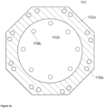
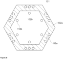
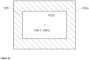
- Figures 3a and 3b shows a first bottom wall (102a, hatched) with a bottom wall mass center (108-1) with an opening (105) having an opening mass center (108-2), wherein the bottom wall mass center (108-1) and the opening mass center (108-2) are both on a fictitious vertical axis.
- Figure 3a shows a top view of the melting vessel (101), wherein the melting section (101a) and the conditioning section (101b) have a rectangular shape.
- Figure 3b shows a top view of the melting vessel (101), wherein the melting section (101a) has a symmetrical octagonal shape and wherein the opening (105) has a circular rim.
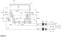
- FIG 4 shows a common controller (107) for controlling two or more heating circuits (110).
- the common controller (107) can control an electrical current of each heating circuit (110) independently of the other heating circuit(s).
- the heating circuits (110) each comprise a frequency changer (113) which is electrically connected via a power factor correction (114) and a transformer (115) to at least two electrodes (116) immersible into the glass melt (120).
- Conductors (117) connect the frequency changers (113), the power factor corrections (114), the transformers (115), and the electrodes (116).
- Signal lines (118) connect the frequency changers (113) with the common controller (107).
- the glass throughput in the melting vessel was kept constant at 42 t/d in all simulations. The following parameters were assessed with respect to the relative minimum dwell time.
- Table 1 Influence of the depth of the conditioning section (d cond_sec ). Arrangement d cond_sec [m] ⁇ T ms-cs (K) t dwell_min [h] t dwell_min_rel [%] rectangular configuration of the melting vessel, 1.3 20 4.7 10 with plate shaped electrodes in both the melting section and the conditioning section 1.6 20 6 12 the depth of the melting section is 1.3 m
- the average temperature difference between the glass melt in the melting section and the glass melt in the conditioning section was kept constant at 20 K.
- the relative minimum dwell time is increased for a melting vessel arrangement with a larger depth of the conditioning section with respect to the depth of the melting section.
- An increase of the relative minimum dwell time t dwell_min_rel benefits the quality of the obtained glass melt.
- Table 2 Influence of the average temperature difference between the glass melt in the melting section and the glass melt in the conditioning section. Arrangement ⁇ T ms-cs (K) t dwell_min [h] t dwell_min_rel [%] rectangular configuration of the melting vessel, with plate shaped electrodes, depth of the melting section: 1.3 m 42 6.6 13 20 6 12 depth of the conditioning section: 1.6 m
- the relative minimum dwell time is increased for a melting vessel arrangement with a larger average temperature difference between the glass melt in the melting section and the glass melt in the conditioning section.
- An increase of the relative minimum dwell time t dwell_min_rel benefits the quality of the obtained glass melt.
- Table 3 Influence of the minimal width of the first bottom wall. Arrangement Minimal width [mm] ⁇ T ms-cs (K) t dwell_min [h] t dwell_min_rel [%] rectangular configuration of the melting vessel, 500 20 6 12 800 20 5.3 11.1 plate-shaped bottom electrodes in both the melting section and the conditioning section 1000 20 4.8 10.7 depth of the melting section: 1.3 m depth of the conditioning section: 1.6 m
Landscapes
- Chemical & Material Sciences (AREA)
- Engineering & Computer Science (AREA)
- Materials Engineering (AREA)
- Organic Chemistry (AREA)
- Chemical Kinetics & Catalysis (AREA)
- Electrochemistry (AREA)
- Physics & Mathematics (AREA)
- Thermal Sciences (AREA)
- Glass Melting And Manufacturing (AREA)
Priority Applications (2)
| Application Number | Priority Date | Filing Date | Title |
|---|---|---|---|
| EP23200790.6A EP4530263B1 (de) | 2023-09-29 | 2023-09-29 | Schmelzgefäss zum schmelzen von glas und verfahren zur herstellung einer glasschmelze |
| PCT/EP2024/076610 WO2025068095A1 (en) | 2023-09-29 | 2024-09-23 | A melting vessel for glass melting, and a method for making a glass melt |
Applications Claiming Priority (1)
| Application Number | Priority Date | Filing Date | Title |
|---|---|---|---|
| EP23200790.6A EP4530263B1 (de) | 2023-09-29 | 2023-09-29 | Schmelzgefäss zum schmelzen von glas und verfahren zur herstellung einer glasschmelze |
Publications (2)
| Publication Number | Publication Date |
|---|---|
| EP4530263A1 true EP4530263A1 (de) | 2025-04-02 |
| EP4530263B1 EP4530263B1 (de) | 2025-08-27 |
Family
ID=88238086
Family Applications (1)
| Application Number | Title | Priority Date | Filing Date |
|---|---|---|---|
| EP23200790.6A Active EP4530263B1 (de) | 2023-09-29 | 2023-09-29 | Schmelzgefäss zum schmelzen von glas und verfahren zur herstellung einer glasschmelze |
Country Status (2)
| Country | Link |
|---|---|
| EP (1) | EP4530263B1 (de) |
| WO (1) | WO2025068095A1 (de) |
Citations (5)
| Publication number | Priority date | Publication date | Assignee | Title |
|---|---|---|---|---|
| US4246432A (en) * | 1977-11-30 | 1981-01-20 | Bayer Aktiengesellschaft | Method and apparatus for melting frits for inorganic oxidic surface coatings by electric resistance heating |
| JPS57205328A (en) * | 1981-06-10 | 1982-12-16 | Nitto Boseki Co Ltd | Electrically melting furnace for directly forming glass product |
| CN203187516U (zh) * | 2013-04-12 | 2013-09-11 | 山东力诺太阳能科技有限公司 | 一种可逆向加电的玻璃窑炉 |
| CN107522387A (zh) * | 2017-09-14 | 2017-12-29 | 中国建材国际工程集团有限公司 | 用于tft玻璃的熔窑 |
| CN107686226A (zh) | 2017-09-14 | 2018-02-13 | 中国建材国际工程集团有限公司 | 用于硼硅酸盐玻璃的熔窑 |
-
2023
- 2023-09-29 EP EP23200790.6A patent/EP4530263B1/de active Active
-
2024
- 2024-09-23 WO PCT/EP2024/076610 patent/WO2025068095A1/en active Pending
Patent Citations (5)
| Publication number | Priority date | Publication date | Assignee | Title |
|---|---|---|---|---|
| US4246432A (en) * | 1977-11-30 | 1981-01-20 | Bayer Aktiengesellschaft | Method and apparatus for melting frits for inorganic oxidic surface coatings by electric resistance heating |
| JPS57205328A (en) * | 1981-06-10 | 1982-12-16 | Nitto Boseki Co Ltd | Electrically melting furnace for directly forming glass product |
| CN203187516U (zh) * | 2013-04-12 | 2013-09-11 | 山东力诺太阳能科技有限公司 | 一种可逆向加电的玻璃窑炉 |
| CN107522387A (zh) * | 2017-09-14 | 2017-12-29 | 中国建材国际工程集团有限公司 | 用于tft玻璃的熔窑 |
| CN107686226A (zh) | 2017-09-14 | 2018-02-13 | 中国建材国际工程集团有限公司 | 用于硼硅酸盐玻璃的熔窑 |
Also Published As
| Publication number | Publication date |
|---|---|
| EP4530263B1 (de) | 2025-08-27 |
| WO2025068095A1 (en) | 2025-04-03 |
Similar Documents
| Publication | Publication Date | Title |
|---|---|---|
| US4693740A (en) | Process and device for melting, fining and homogenizing glass | |
| CN101980977B (zh) | 熔融玻璃制造装置及采用该制造装置的熔融玻璃制造方法 | |
| CN110357399B (zh) | 用于生产玻璃产品的方法及适于此的装置 | |
| CN113480144A (zh) | 一种基于溢流下拉法生产柔性玻璃的澄清均化系统及方法 | |
| US20250187965A1 (en) | Feeder alcove and batch feeding apparatus for a melter | |
| CN103332850B (zh) | 一种光学玻璃生产线 | |
| US20200102240A1 (en) | Schmelzwanne und glasschmelzanlage | |
| EP4530263B1 (de) | Schmelzgefäss zum schmelzen von glas und verfahren zur herstellung einer glasschmelze | |
| WO2024076515A1 (en) | Apparatus and method for cooling molten glass in a conduit | |
| CN107915394A (zh) | 一种钙镁铝硅建筑浮法微晶玻璃料道及其使用方法 | |
| EP4345069A1 (de) | Gefässsystem zur herstellung und läuterung einer glasschmelze und verfahren zur herstellung und läuterung einer glasschmelze | |
| CN103359910A (zh) | 玻璃板的制造方法 | |
| WO2025068384A1 (en) | A vessel system for producing and refining a glass melt, and method for producing and refining a glass melt | |
| JP7844461B2 (ja) | ガラス製造装置 | |
| CN121969582A (zh) | 用于玻璃熔融的熔融容器以及玻璃熔体的制造方法 | |
| EP4530264B1 (de) | Steigrohr für ein läutergefäss und verfahren zum läutern einer glasschmelze | |
| EP4530261A1 (de) | Verfahren und vorrichtung zur herstellung eines glasprodukts | |
| EP4570764A1 (de) | Verfahren und vorrichtung zur herstellung eines glasprodukts | |
| CN205953821U (zh) | 一种光学玻璃窑炉熔化池 | |
| EP4530262A1 (de) | Läutergefäss zum läutern einer glasschmelze und verfahren zum läutern einer glasschmelze | |
| EP0152444A1 (de) | Herstellung von glasgegenständen | |
| EP3907196A1 (de) | Ofen für gleichzeitiges schmelzen mehrerer gläser | |
| TWI915447B (zh) | 玻璃製造裝置 | |
| US20250230087A1 (en) | Fining of submerged combustion or other glass | |
| US12612325B2 (en) | Glass manufacturing apparatus |
Legal Events
| Date | Code | Title | Description |
|---|---|---|---|
| STAA | Information on the status of an ep patent application or granted ep patent |
Free format text: STATUS: EXAMINATION IS IN PROGRESS |
|
| PUAI | Public reference made under article 153(3) epc to a published international application that has entered the european phase |
Free format text: ORIGINAL CODE: 0009012 |
|
| 17P | Request for examination filed |
Effective date: 20231002 |
|
| AK | Designated contracting states |
Kind code of ref document: A1 Designated state(s): AL AT BE BG CH CY CZ DE DK EE ES FI FR GB GR HR HU IE IS IT LI LT LU LV MC ME MK MT NL NO PL PT RO RS SE SI SK SM TR |
|
| GRAP | Despatch of communication of intention to grant a patent |
Free format text: ORIGINAL CODE: EPIDOSNIGR1 |
|
| STAA | Information on the status of an ep patent application or granted ep patent |
Free format text: STATUS: GRANT OF PATENT IS INTENDED |
|
| INTG | Intention to grant announced |
Effective date: 20250604 |
|
| GRAS | Grant fee paid |
Free format text: ORIGINAL CODE: EPIDOSNIGR3 |
|
| GRAA | (expected) grant |
Free format text: ORIGINAL CODE: 0009210 |
|
| STAA | Information on the status of an ep patent application or granted ep patent |
Free format text: STATUS: THE PATENT HAS BEEN GRANTED |
|
| P01 | Opt-out of the competence of the unified patent court (upc) registered |
Free format text: CASE NUMBER: APP_31675/2025 Effective date: 20250701 |
|
| AK | Designated contracting states |
Kind code of ref document: B1 Designated state(s): AL AT BE BG CH CY CZ DE DK EE ES FI FR GB GR HR HU IE IS IT LI LT LU LV MC ME MK MT NL NO PL PT RO RS SE SI SK SM TR |
|
| REG | Reference to a national code |
Ref country code: CH Ref legal event code: EP |
|
| REG | Reference to a national code |
Ref country code: DE Ref legal event code: R096 Ref document number: 602023006075 Country of ref document: DE |
|
| REG | Reference to a national code |
Ref country code: IE Ref legal event code: FG4D |
|
| PGFP | Annual fee paid to national office [announced via postgrant information from national office to epo] |
Ref country code: DE Payment date: 20250919 Year of fee payment: 3 |
|
| PGFP | Annual fee paid to national office [announced via postgrant information from national office to epo] |
Ref country code: AT Payment date: 20251020 Year of fee payment: 3 |
|
| REG | Reference to a national code |
Ref country code: NL Ref legal event code: MP Effective date: 20250827 |
|
| PG25 | Lapsed in a contracting state [announced via postgrant information from national office to epo] |
Ref country code: IS Free format text: LAPSE BECAUSE OF FAILURE TO SUBMIT A TRANSLATION OF THE DESCRIPTION OR TO PAY THE FEE WITHIN THE PRESCRIBED TIME-LIMIT Effective date: 20251227 |
|
| PG25 | Lapsed in a contracting state [announced via postgrant information from national office to epo] |
Ref country code: NO Free format text: LAPSE BECAUSE OF FAILURE TO SUBMIT A TRANSLATION OF THE DESCRIPTION OR TO PAY THE FEE WITHIN THE PRESCRIBED TIME-LIMIT Effective date: 20251127 |
|
| REG | Reference to a national code |
Ref country code: LT Ref legal event code: MG9D |
|
| PG25 | Lapsed in a contracting state [announced via postgrant information from national office to epo] |
Ref country code: PT Free format text: LAPSE BECAUSE OF FAILURE TO SUBMIT A TRANSLATION OF THE DESCRIPTION OR TO PAY THE FEE WITHIN THE PRESCRIBED TIME-LIMIT Effective date: 20251229 |
|
| PG25 | Lapsed in a contracting state [announced via postgrant information from national office to epo] |
Ref country code: FI Free format text: LAPSE BECAUSE OF FAILURE TO SUBMIT A TRANSLATION OF THE DESCRIPTION OR TO PAY THE FEE WITHIN THE PRESCRIBED TIME-LIMIT Effective date: 20250827 |
|
| PGFP | Annual fee paid to national office [announced via postgrant information from national office to epo] |
Ref country code: IT Payment date: 20250930 Year of fee payment: 3 |
|
| PG25 | Lapsed in a contracting state [announced via postgrant information from national office to epo] |
Ref country code: HR Free format text: LAPSE BECAUSE OF FAILURE TO SUBMIT A TRANSLATION OF THE DESCRIPTION OR TO PAY THE FEE WITHIN THE PRESCRIBED TIME-LIMIT Effective date: 20250827 Ref country code: NL Free format text: LAPSE BECAUSE OF FAILURE TO SUBMIT A TRANSLATION OF THE DESCRIPTION OR TO PAY THE FEE WITHIN THE PRESCRIBED TIME-LIMIT Effective date: 20250827 |
|
| PGFP | Annual fee paid to national office [announced via postgrant information from national office to epo] |
Ref country code: FR Payment date: 20251030 Year of fee payment: 3 |
|
| PG25 | Lapsed in a contracting state [announced via postgrant information from national office to epo] |
Ref country code: GR Free format text: LAPSE BECAUSE OF FAILURE TO SUBMIT A TRANSLATION OF THE DESCRIPTION OR TO PAY THE FEE WITHIN THE PRESCRIBED TIME-LIMIT Effective date: 20251128 |
|
| PG25 | Lapsed in a contracting state [announced via postgrant information from national office to epo] |
Ref country code: SE Free format text: LAPSE BECAUSE OF FAILURE TO SUBMIT A TRANSLATION OF THE DESCRIPTION OR TO PAY THE FEE WITHIN THE PRESCRIBED TIME-LIMIT Effective date: 20250827 |
|
| PG25 | Lapsed in a contracting state [announced via postgrant information from national office to epo] |
Ref country code: LV Free format text: LAPSE BECAUSE OF FAILURE TO SUBMIT A TRANSLATION OF THE DESCRIPTION OR TO PAY THE FEE WITHIN THE PRESCRIBED TIME-LIMIT Effective date: 20250827 |
|
| PG25 | Lapsed in a contracting state [announced via postgrant information from national office to epo] |
Ref country code: BG Free format text: LAPSE BECAUSE OF FAILURE TO SUBMIT A TRANSLATION OF THE DESCRIPTION OR TO PAY THE FEE WITHIN THE PRESCRIBED TIME-LIMIT Effective date: 20250827 Ref country code: PL Free format text: LAPSE BECAUSE OF FAILURE TO SUBMIT A TRANSLATION OF THE DESCRIPTION OR TO PAY THE FEE WITHIN THE PRESCRIBED TIME-LIMIT Effective date: 20250827 |
|
| PG25 | Lapsed in a contracting state [announced via postgrant information from national office to epo] |
Ref country code: RS Free format text: LAPSE BECAUSE OF FAILURE TO SUBMIT A TRANSLATION OF THE DESCRIPTION OR TO PAY THE FEE WITHIN THE PRESCRIBED TIME-LIMIT Effective date: 20251127 |
|
| PG25 | Lapsed in a contracting state [announced via postgrant information from national office to epo] |
Ref country code: ES Free format text: LAPSE BECAUSE OF FAILURE TO SUBMIT A TRANSLATION OF THE DESCRIPTION OR TO PAY THE FEE WITHIN THE PRESCRIBED TIME-LIMIT Effective date: 20250827 |
|
| REG | Reference to a national code |
Ref country code: AT Ref legal event code: MK05 Ref document number: 1829853 Country of ref document: AT Kind code of ref document: T Effective date: 20250827 |
|
| PG25 | Lapsed in a contracting state [announced via postgrant information from national office to epo] |
Ref country code: RO Free format text: LAPSE BECAUSE OF FAILURE TO SUBMIT A TRANSLATION OF THE DESCRIPTION OR TO PAY THE FEE WITHIN THE PRESCRIBED TIME-LIMIT Effective date: 20250827 |
|
| PG25 | Lapsed in a contracting state [announced via postgrant information from national office to epo] |
Ref country code: SM Free format text: LAPSE BECAUSE OF FAILURE TO SUBMIT A TRANSLATION OF THE DESCRIPTION OR TO PAY THE FEE WITHIN THE PRESCRIBED TIME-LIMIT Effective date: 20250827 |
|
| PG25 | Lapsed in a contracting state [announced via postgrant information from national office to epo] |
Ref country code: DK Free format text: LAPSE BECAUSE OF FAILURE TO SUBMIT A TRANSLATION OF THE DESCRIPTION OR TO PAY THE FEE WITHIN THE PRESCRIBED TIME-LIMIT Effective date: 20250827 |
|
| PG25 | Lapsed in a contracting state [announced via postgrant information from national office to epo] |
Ref country code: AT Free format text: LAPSE BECAUSE OF FAILURE TO SUBMIT A TRANSLATION OF THE DESCRIPTION OR TO PAY THE FEE WITHIN THE PRESCRIBED TIME-LIMIT Effective date: 20250827 |