EP4530262A1 - Läutergefäss zum läutern einer glasschmelze und verfahren zum läutern einer glasschmelze - Google Patents
Läutergefäss zum läutern einer glasschmelze und verfahren zum läutern einer glasschmelze Download PDFInfo
- Publication number
- EP4530262A1 EP4530262A1 EP23200772.4A EP23200772A EP4530262A1 EP 4530262 A1 EP4530262 A1 EP 4530262A1 EP 23200772 A EP23200772 A EP 23200772A EP 4530262 A1 EP4530262 A1 EP 4530262A1
- Authority
- EP
- European Patent Office
- Prior art keywords
- glass melt
- fining vessel
- side wall
- height
- melt
- Prior art date
- Legal status (The legal status is an assumption and is not a legal conclusion. Google has not performed a legal analysis and makes no representation as to the accuracy of the status listed.)
- Pending
Links
Images
Classifications
-
- C—CHEMISTRY; METALLURGY
- C03—GLASS; MINERAL OR SLAG WOOL
- C03B—MANUFACTURE, SHAPING, OR SUPPLEMENTARY PROCESSES
- C03B5/00—Melting in furnaces; Furnaces so far as specially adapted for glass manufacture
- C03B5/16—Special features of the melting process; Auxiliary means specially adapted for glass-melting furnaces
- C03B5/225—Refining
- C03B5/2257—Refining by thin-layer fining
-
- C—CHEMISTRY; METALLURGY
- C03—GLASS; MINERAL OR SLAG WOOL
- C03B—MANUFACTURE, SHAPING, OR SUPPLEMENTARY PROCESSES
- C03B5/00—Melting in furnaces; Furnaces so far as specially adapted for glass manufacture
- C03B5/16—Special features of the melting process; Auxiliary means specially adapted for glass-melting furnaces
- C03B5/18—Stirring devices; Homogenisation
- C03B5/182—Stirring devices; Homogenisation by moving the molten glass along fixed elements, e.g. deflectors, weirs, baffle plates
-
- C—CHEMISTRY; METALLURGY
- C03—GLASS; MINERAL OR SLAG WOOL
- C03B—MANUFACTURE, SHAPING, OR SUPPLEMENTARY PROCESSES
- C03B5/00—Melting in furnaces; Furnaces so far as specially adapted for glass manufacture
- C03B5/16—Special features of the melting process; Auxiliary means specially adapted for glass-melting furnaces
- C03B5/18—Stirring devices; Homogenisation
- C03B5/183—Stirring devices; Homogenisation using thermal means, e.g. for creating convection currents
- C03B5/185—Electric means
-
- C—CHEMISTRY; METALLURGY
- C03—GLASS; MINERAL OR SLAG WOOL
- C03B—MANUFACTURE, SHAPING, OR SUPPLEMENTARY PROCESSES
- C03B5/00—Melting in furnaces; Furnaces so far as specially adapted for glass manufacture
- C03B5/16—Special features of the melting process; Auxiliary means specially adapted for glass-melting furnaces
- C03B5/20—Bridges, shoes, throats, or other devices for withholding dirt, foam, or batch
Definitions
- This disclosure relates to a fining vessel for refining a glass melt, and a method for refining a glass melt by means of which an excellent glass quality is achieved.
- the production of glass has a high carbon footprint due to the amount of energy required for the melting and fining processes. This is particularly the case for heating by gas burners which use natural gas.
- a reduction of the carbon footprint is possible if, instead, an electric resistance heating is used which is provided with power from renewable energy sources like wind power, waterpower, or solar panels.
- the same power sources may also be used to produce hydrogen by electrolysis which then can be used to feed the gas burners. While the latter requires less changes to an existing glass production facility with a gas burner heating, the intermediate step of electrolysis is associated with a considerable energy loss. Hence, a direct use of the electrical power is more desirable.
- glass compositions There are various kinds of glass compositions. Some glass compositions are relatively easy to manufacture in good quality, others require sophisticated equipment and/or extremely well-balanced production processes. Generally, the glass compositions used to make drinking glasses and bottles, ordinary windowpanes, and other construction glass products, e.g., glass wool used for insulation, are relatively easy to manufacture in good quality because the glass used for these products has rather low melting temperatures and a steep viscosity-temperature curve. Additionally, quality criteria of these manufactured products are not very stringent. For example, drinking glasses and construction glass products may contain an occasional bubble and solid inclusion, and variations in shape and dimension are tolerable. These glass products may contain impurities to a certain extent because their use does not require defined light transmission properties, or stringent purity regulations.
- the types of glass compositions used for many mass products have low melting temperatures because of significant amounts of alkali metal oxides and alkaline earth metal oxides.
- the respective glass melting facilities achieve very high throughput, often more than 200 tons of glass per day, or even 400 tons per day. Naturally, the amount of energy needed for making 200 tons of low melting glass is significantly lower than for a higher melting glass.
- the quality required for a given product depends on its intended use.
- Some high-quality glasses are used to make products that do not entertain the occasional bubble and must meet stringent criteria in terms of shape, dimensional variations, and purity (both chemical and optical). Many of these glasses are rather difficult to manufacture not only because of the stringent criteria but also because of high melting temperatures. High melting temperatures may be necessary to achieve melt viscosities sufficient for homogenization and removal of bubbles from the melt.
- Examples of high-quality glass products include pharmaceutical containers and glass tubes used for making such containers. These glasses are often melted in fossil fuel heated vessels where energy is supplied from gas burners in the crown above the glass melt. This technology allows high glass melting temperatures and leads to specialty glass of reasonable quality. The disadvantage of these fossil fuel heated vessels is the huge amount of fossil energy needed for heating purposes. There is an option to melt the glass in fully electric heated vessels with a cold crown, but these vessels do not provide the quality needed in specialty glass applications.
- a crucial step in the production of glass products that meet high-quality criteria rests in the fining step.
- Refining aims at the removal of bubbles from the glass melt by suitably high temperatures, optionally accompanied by stirring of the glass melt. It is generally assisted by refining agents which undergo chemical reactions and force gaseous components, such as e.g., H 2 O, HF, HCl, CO 2 , SO 2 and O 2 and other compounds with high partial pressure at refining temperature, out of the glass melt.
- gaseous components such as e.g., H 2 O, HF, HCl, CO 2 , SO 2 and O 2 and other compounds with high partial pressure at refining temperature, out of the glass melt.
- design considerations of the fining vessel play an important role to provide for an efficient refining of the glass melt.
- CN 107686226 A discloses a melting kiln for borosilicate glass comprises a cold-top melting furnace which is exclusively heated by electric means and a clarifier for, respectively heating and refining a glass melt.
- a liquid flow hole is provided at the bottom of the cold-top melting furnace, wherein an outlet end of the flow hole communicates with a lower end of a vertically arranged rising channel through which the molten glass passes. The upper end of the rising channel communicates with and feeds the molten glass into an inlet of the clarifier.
- the upper part of the cold-top melting furnace is provided with a feeding port for supplying borosilicate batch materials.
- the inner side of the cold-top melting furnace is provided with multiple kiln electrodes for heating by electric means.
- the interior of the clarifier is provided with a plurality of electrodes and a plurality of gas burners.
- all gas burners may be arranged in the upper part of the clarifier.
- a bubbling device may be disposed on the bottom brick of the clarifier to assist and improve refining the glass melt.
- this disclosure relates to a method for refining a glass melt, comprising the steps of
- this disclosure relates to a fining vessel (301) for refining a glass melt (302), the fining vessel having a first side wall (303-1), a second side wall (303-2), a bottom (304) and an optional ramp (315), the fining vessel (301) having a middle part (311), wherein the fining vessel (301) is connectable to an optional upstream part (309) for receiving the glass melt (302), and wherein the fining vessel (301) is connectable to an optional downstream part (310) for purging a refined glass (302") melt, wherein the optional upstream part (309), the middle part (311), a part above the optional ramp (315) and the optional downstream part (310) are arrangeable or arranged in this consecutive order, wherein the middle part (311) has a width w m , wherein the width w m is the shortest distance between the first side wall (303-1) and the second side wall (303-2) at a height of 30 cm above a deepest point of the bottom (304), wherein the fining vessel (301) comprises
- the fining vessel (301) provides for a so-called flat-bed refining method.
- the method is thus run under the constraint that the glass melt (302) in the fining vessel (301) has a working height h melt of at least 0.35 m, wherein h melt is at most 0.6 m, for fining to take place.
- the fining vessel (301) is designed and operated in such a way that fining takes place mainly, or even entirely, in the middle part (311).
- the fining vessel (301) according to this disclosure is designed in such a way to allow small bubbles to form and to leave the glass melt.
- this disclosure relates to a fining vessel (301) for refining a glass melt (302), the fining vessel having a first side wall (303-1), a second side wall (303-2), a bottom (304) and an optional ramp (315), the fining vessel (301) having a middle part (311), wherein the fining vessel (301) is connectable to an optional upstream part (309) for receiving the glass melt (302'), and wherein the fining vessel (301) is connectable to an optional downstream part (310) for purging a refined glass melt (302"), wherein the optional upstream part (309), the middle part (311), a part above the optional ramp (315) and the optional downstream part (310) are arrangeable or arranged in this consecutive order, wherein the middle part (311) has a width w m , wherein the width w m is the shortest distance between the first side wall (303-1) and the second side wall (303-2) at a height of 30 cm above a deepest point of the bottom (304), wherein the fining vessel (30
- this disclosure relates to a fining vessel (301) for refining a glass melt (302), the fining vessel having a first side wall (303-1), a second side wall (303-2), a bottom (304) and a ramp (315), the fining vessel (301) having a middle part (311), wherein the fining vessel (301) is connectable to an optional upstream part (309) for receiving the glass melt (302'), and wherein the fining vessel (301) is connectable to an optional downstream part (310) for purging a refined glass melt (302"), wherein the optional upstream part (309), the middle part (311), a part above the optional ramp (315) and the optional downstream part (310) are arrangeable or arranged in this consecutive order, wherein the middle part (311) has a width w m , wherein the width w m is the shortest distance between the first side wall (303-1) and the second side wall (303-2) at a height of 30 cm above a deepest point of the bottom (304), wherein the ramp (315)
- this disclosure relates to an apparatus comprising a fining vessel (301) according to this disclosure and a riser duct (308), wherein the riser duct (308) is arrangeable or arranged upstream of the fining vessel (301).
- the riser duct (308) allows feeding a glass melt into the fining vessel (301), which has been previously generated in a melting vessel.
- the riser duct (308) thus serves as a transport system between the melting vessel and fining vessel (301) and allows heating the glass melt to an appropriate temperature.
- the glass melt may be heated to a temperature of at least T2 which corresponds to a viscosity of the glass melt (302) of 10 2 dPa ⁇ s which establishes fining conditions.
- T2 a temperature of at least T2 which corresponds to a viscosity of the glass melt (302) of 10 2 dPa ⁇ s which establishes fining conditions.
- large bubbles with a diameter of more than 500 ⁇ m may readily escape the glass melt via the glass melt surface and while they are still in the section of the riser duct.
- Smaller bubbles with a diameter of 500 ⁇ m or less require the fining vessel (301) according to this disclosure to leave the glass melt via the surface and to thus achieve sufficient fining with a view to
- this disclosure relates to an apparatus comprising a fining vessel (301) according to this disclosure and a riser duct (308) and/or a vertical duct (312), wherein the riser duct (308) is arrangeable or arranged upstream of the fining vessel (301) and/or wherein the vertical duct (312) is arrangeable or arranged downstream of the fining vessel (301).
- a "glass melt” is a volume of a batch of glass materials that has a viscosity of less than 10 7.6 dPas. Such a viscosity can be measured using the fiber elongation method, e.g. as described in DIN ISO 7884-6:1998-02, where the elongation speed of a fiber with a defined diameter is determined with different weights at different temperatures.
- the temperature at which the glass melt has a viscosity of 10 2 dPas is herein called “temperature T2".
- the temperature at which the glass melt has a viscosity of 10 4 dPas is herein called “temperature T4".
- Temperature T2 is less than 1,500 °C for glass compositions with high contents of alkali metal oxides or alkaline earth metal oxides, such as soda lime glass and other glass compositions. These viscosities can be measured using a rotational viscosimeter, e.g. as described in DIN ISO 7884-2:1998-2.
- t is the temperature under consideration.
- A, B and t 0 are the so-called VFT constants that are specific for each glass composition.
- the middle part (311) refers to a fictitious volume within the fining vessel (301), wherein the fictitious volume is characterised by a length l m , a height h m , and a width w m .
- the middle part (311) of the fining vessel has a height h m which is at most 0.63 m with respect to the deepest point of the bottom (304).
- the middle part (311) has a width w m , wherein the width w m is the shortest distance between the first side wall (303-1) and the second side wall (303-2) at a height of 30 cm above a deepest point of the bottom (304).
- the width may vary at different heights.
- the middle part of the fining vessel has a length l m which extends in horizontal and orthogonal direction with respect to the width w m , wherein the length l m extends from the upstream part (309) to the downstream part (310), not including the upstream part (309) and the downstream part (310).
- the length l m shall thus be understood as the shortest distance measured from the geometrical interface of the upstream part and the middle part until the downstream part begins.
- Dwell time is the time that a given portion of the glass melt spends in a part of the apparatus, e.g., the middle part of the fining vessel before being withdrawn from the middle part. Dwell time can be measured using so-called tracers, i.e., components that are added to the glass melt so that they can be detected in the product, allowing conclusions as to the time spent in the fining vessel. Examples of tracer elements are Ca, Sr and Y.
- the "average dwell time” is defined as: middle part volume m 3 middle part throughput m 3 h
- the “middle part volume” is the volume of the glass melt which is required to fill the middle part until a certain working height h melt .
- the working height of the glass melt shall be determined in relation to the deepest point of the bottom (304).
- the “middle part volume” thus excludes the volume of the barrier element (313) which is not accessible to the glass melt.
- the “middle part volume” is the volume of the glass melt which is required to fill the middle part until a certain working height h melt as if the ramp was not present.
- the "average dwell time” describes the time average which the glass melt takes to pass through a part of an apparatus
- the “minimum dwell time” describes the shortest time that an individualized portion of the glass melt passes through a certain part of the apparatus.
- the “minimum dwell time” can also be measured using so-called tracers, for example by adding tracers to the batch of raw materials when fed into the melting vessel and by measuring the time it takes to detect said tracers at the downstream end of the melting vessel.
- the "minimum dwell time" of the glass melt in the middle part of the fining vessel can be measured by adding tracers to the glass melt in the upstream part and measuring the time it takes to detect said tracers in the downstream part.
- length always refers to a maximal extension in the x-direction
- width always refers to a maximal extension in the y-direction
- height always refers to a maximal extension in the z-direction, wherein the x-direction, y-direction and z-direction are oriented pairwise perpendicular to each other.
- the fining vessel according to this disclosure has a first side wall (303-1), a second side wall (303-2), and a bottom (304), all of which form geometrical planes which may be curved or flat.
- glass throughput refers to an amount of glass, for example given in tons or cubic meters, processed through a middle part volume or an area per time, for example given in days. Accordingly, a ratio between the glass throughput and an area may be expressed in tons per day per square meter, i.e., t/(d ⁇ m 2 ). Accordingly, a ratio between the glass throughput in m 3 /d and a middle part volume may be expressed in 'per day' or 'day to the power of minus one', i.e., d -1 .
- the glass melt (302) has a fictitious top layer (318) and a fictitious bottom layer (319).
- the fictitious top layer (318) consists of the portion of the glass melt (302) in the middle part volume which extends from the surface of the glass melt (307) into the glass melt (302) with a thickness of 10 cm.
- the fictitious bottom layer (319) consists of the portion of the glass melt (302) in the middle part volume which extends from the bottom (304) into the glass melt (302) with a thickness of 10 cm.
- the middle part volume is the volume of the glass melt (302) which is required to fill the middle part (311) up to the working height h melt .
- the average temperature of the glass melt in the fictitious top layer (318) refers to the arithmetic mean of the temperature readings using two or more top temperature probes (320) located at the same horizontal positions as the mid-height of the fictitious top layer (318), viewed in a side view of the fining vessel (301).
- the average temperature of the glass melt in the fictitious bottom layer (319) refers to the arithmetic mean of the temperature readings using two or more bottom temperature probes (321) located at the same horizontal positions as the mid-height of the fictitious bottom layer (319), viewed in a side view of the fining vessel (301).
- the two or more top temperature probes (320) and the two or more bottom temperature probes (321) are arranged in a section of the middle part (311) which belongs to a region between 0.4 and 0.6 l m (e.g. at 0.5 l m ) along the length l m of the middle part (311).
- the two or more top temperature probes (320), and the two or more bottom temperature probes (321) may be attached to the wall or the bottom of the fining vessel and are arranged in such a way that the actual temperature measurement happens at least 5 cm away from the wall and/or the bottom. In other words, the actual temperature measurement happens within the glass melt.
- the average temperature of the glass melt refers to the arithmetic mean of the temperature readings using two or more top temperature probes (320) located at the same horizontal positions, viewed in a side view of the fining vessel (301).
- the gas bubbles generated as a result of the fining process are assumed to be spherical and are thus geometrically defined in terms of the equivalent spherical diameter.
- the terminology 'diameter' in relation to the gas bubble size shall thus be understood as the equivalent spherical diameter.
- the fining vessel (301) according to this disclosure provides for flat-bed refining and may be advantageously used in a method according to this disclosure. Features described in the context of the fining vessel (301) are thus applicable to the method according to this disclosure as far as they concern the fining vessel (301).
- the fining vessel may have an optional ramp (315) which is intended to let the glass melt flow downwards after fining of said glass melt.
- the fining vessel (301) has a middle part (311), where fining shall take place, i.e., the temperature of the glass melt in said middle part needs to be raised to a temperature which is sufficient to let fining take place as part of the method.
- the fining vessel (301) is connectable to an optional upstream part (309) for receiving the glass melt (302').
- the fining vessel (301) is also connectable to an optional downstream part (310), i.e., a vertical duct (312), for purging a refined glass melt. It shall be understood that fining essentially takes place in the middle part (311) of the fining vessel, and, if present, possibly also in the part above the ramp.
- the optional upstream part (309), the middle part (311), a part above the optional ramp (315) and the optional downstream part (310) are arrangeable or arranged in this consecutive order. Likewise, if all optional parts are present, the upstream part (309), the middle part (311), a part above the ramp (315) and the downstream part (310) are arranged in this consecutive order. That means during the method, a glass melt will always be fed from the upstream part and proceed through the middle part, subsequently above the ramp, and finally via the downstream part.
- the middle part (311) has a width w m , which is the shortest distance between the first side wall (303-1) and the second side wall (303-2) at a height of 30 cm above a deepest point of the bottom (304).
- w m the width of the first side wall (303-1) and the second side wall (303-2) at a height of 30 cm above a deepest point of the bottom (304).
- the width w m needs to be established for all of said two or more 'deepest points' at a height of 30 cm, and the shortest distance between the first side wall (303-1) and the second side wall (303-2) needs to be established out of all of said 'deepest points'.
- the middle part (311) may comprise a barrier element (313) which is arranged on the bottom (304).
- the barrier element (313) extends from the first side wall to the second side wall such that it provides a barrier to a glass flow.
- the barrier element (313) thus covers a lower portion of a cross-section of the middle part (311).
- the barrier element may have a variable height between the first side wall and the second side wall.
- the barrier element has a characteristic height h w which is the vertical distance between the deepest point of the bottom (304) and the highest height of the barrier element (313), with the proviso that h w ⁇ 30 cm.
- the fining vessel according to this disclosure provides for so-called flat-bed refining.
- the middle part (311) of the fining vessel may have a height h m which is at most 0.63 m.
- the height h m is the vertical distance between a deepest point of the bottom (304) and the lowest height of the first side wall (303-1) or the second side wall (303-2).
- the middle part of the fining vessel has a length l m which extends in horizontal and orthogonal direction with respect to the width w m , wherein the length l m extends from the upstream part to the downstream part, not including the upstream part and the downstream part.
- the length l m shall thus be understood as the shortest distance measured from the geometrical interface of the upstream part and the middle part until the downstream part begins.
- the barrier element (313) may be arranged in a section of the middle part (311) which belongs to a region between 0.8 and 1.0 l m along the length l m of the middle part (311).
- the barrier element (313) may be arranged in a section of the middle part (311) which belongs to a region between 0.0 and 0.2 l m along the length l m of the middle part (311).
- the position of 0.0 l m shall be understood as the geometrical interface of the upstream part to the middle part.
- the position of 1.0 l m shall be understood as the geometrical interface of the middle part and the downstream part. In case the ramp is present, the position of 1.0 l m shall be understood as the geometrical interface of the middle part and the downstream part, with a second interface between the ramp and the downstream part.
- the fining vessel (301) may comprise a ramp (315), the ramp having a height h, of 0.1 to 1.0 m with respect to the highest point of the ramp and the lowest point of the ramp.
- the ramp is arranged in downstream direction after the middle part and allows the refined glass melt to flow downwards.
- the ramp may either be shaped as a curved plane or as a flat plane. In the case of a flat plane, the ramp may have a constant slope.
- the fining vessel (301) may have a superstructure (305) which covers the fining vessel. It shall be understood that the superstructure makes at least partial physical contact with both the upper edge of the first side wall (303-1) and the upper edge of the second side wall (303-2). It is preferred that the superstructure makes full or continuous physical contact with both the upper edge of the first side wall (303-1) and the upper edge of the second side wall (303-2) to thus provide a complete cover above the middle part and, if present, the ramp.
- the temperature of the inner volume of the superstructure may be controlled with a temperature probe (322). It shall be understood that the temperature probe (322) thus monitors the temperature of the inner volume of the superstructure and also allows adjusting the temperature of the inner volume of the superstructure.
- the working height h melt is the filling of the middle part with a glass melt in a height direction.
- the working height h melt is at least 0.35 m to provide for a reasonable amount of glass melt which is subjected to fining in the middle part.
- the barrier element (313) has a height h w of at least 0.30 m, with the proviso that h melt ⁇ 1.2 ⁇ h w , in order to guarantee that a sufficient amount of glass melt is provided which can pass and flow over the barrier element.
- the fining vessel (301) may comprise one or more heating burners (314) arranged above the bottom (304) at a height of at least 0.9 m, or at least 1.5 m, above the deepest point of the bottom (304). It shall be understood that the one or more heating burners allow heating the glass melt to a temperature which is sufficient for fining under the constraint that the one or more heating burners do not touch or get in physical contact with the glass melt.
- the glass melt (302) may be heated by means of electrodes which are placed in such a way that they are in direct physical contact with the glass melt and by means of one or more heating burners (314) arranged above the glass melt.
- the one or more heating burners may provide more thermal energy to the glass melt than the electrodes which leads to glass melt layers of different temperature.
- the glass melt (302) may have a fictitious top layer (318) at melt level, i.e., directly below the surface (307), and a fictitious bottom layer (319) above bottom (304).
- Each of the fictitious top layer (318) and the fictitious bottom layer (319) may have a thickness extension of, e.g., 10 cm in height.
- An average temperature of the glass melt in the fictitious top layer (318) may be at least 10 K higher than an average temperature of the glass melt in the fictitious bottom layer (319).
- this disclosure relates to a method for refining a glass melt, comprising the steps of
- the step 'providing a glass melt (302)' comprises prior heating of the glass melt (302) to a temperature of at least T2 which corresponds to a viscosity of the glass melt (302) of 10 2 dPa ⁇ s. Said prior heating thus establishes fining conditions.
- the step 'feeding the glass melt into a fining vessel (301)' is realized via a riser duct as the upstream part (309).
- Said means allows a continuous filling of the glass melt into the fining vessel (301) and maintaining a desirable glass melt level which thus enables flat-bed refining.
- the riser duct and the fining vessel act as communicating sections, wherein the flow conditions of the glass melt in the riser duct directly influence and control the flow conditions of the glass melt in the fining vessel.
- the method comprises the step of heating the glass melt by means of a heating burner (314) arranged within a gaseous phase (306), wherein the heating burner (314) can optionally be heated with fuel gas and oxygen, or fuel gas and air, or a mixture of hydrogen and oxygen, or with natural gas and oxygen, or with a mixture of natural gas, hydrogen and oxygen, or ammonia and oxygen, or biomethane, or biofuel.
- the heating burner (314) can be heated with a mixture of hydrogen and air, or with natural gas and air, or with a blend of natural gas and hydrogen with air.
- the heating burner (314) may be heated with a combustion mixture which is free of fossil fuel.
- free of fossil fuel means that the combustion mixture comprises less 1.0 wt.% of fossil fuel, or less than 0.1 wt.% of fossil fuel.
- the method comprises the step of heating the glass melt (302) by means of two or more heating circuits (316) each comprising at least one pair of electrodes (317), wherein one or more or all electrodes are rod-shaped, plate-shaped, block-shaped and/or tube-shaped.
- the electrodes are arranged in a vertical or a horizontal or an oblique orientation in or on the side walls (303) or arranged in a horizontal or a vertical or an oblique orientation in or on the bottom (304).
- the electrodes comprise a platinum-rhodium alloy. In one embodiment, the electrodes comprise a molybdenum-tungsten alloy. In one embodiment, the electrodes comprise molybdenum and ZrOz dispersed therein.
- the electrode material is chosen such that corrosion at the high process temperatures is kept to a minimum.
- the method comprises the step of cooling the first side wall (303-1), the second side wall (303-2) and/or the bottom (304). In one embodiment, the method comprises the step of cooling the barrier element (313). In one embodiment, the method comprises the step of cooling the first side wall (303-1), the second side wall (303-2), the bottom (304) and the barrier element (313). Said measure avoids corrosion of the refractory materials comprised in the walls and/or the barrier element. In one embodiment cooling the first side wall (303-1), the second side wall (303-2) and/or the bottom (304) is realized by water cooling and/or air cooling. Air cooling is more advantageous because it allows a better balance between the need for cooling to minimize corrosion while retaining sufficiently high temperatures which are a requirement for the fining process.
- cooling the barrier element (313) is realized by water cooling and/or air cooling, wherein the barrier element (313) optionally comprises or consists of platinum, molybdenum or iridium or alloys thereof. In one embodiment cooling the barrier element (313) is realized by water cooling and/or air cooling, wherein the barrier element (313) comprises a ceramic material which may optionally be covered or shielded with platinum, molybdenum or iridium or alloys thereof. In the absence of cooling, the barrier element (313) advantageously comprises a ceramic material which may be covered or shielded with platinum, molybdenum or iridium or alloys thereof to minimize corrosion. In an embodiment of the method which employs cooling of the barrier element (313), e.g., by water cooling and/or air cooling, the barrier element (313) may comprise or consist of a ceramic material which provides sufficient protection against corrosion during the lifetime of the fining vessel.
- one or more of the following conditions apply:
- the working height h melt of the glass melt (302) and the height h w of the barrier element (313) are related by h melt > h w + 0.05 m, or h melt > h w + 0.10 m, or h melt > h w + 0.15 m.
- h melt > h melt of the glass melt (302) which is at most 0.6 m it is advantageous to adjust the height h w of the barrier element (313) in such a way that it provides a hindrance for the glass melt which benefits fining because above the barrier element the glass melt becomes thinner so that gas bubbles are forced to leave the glass melt.
- the glass melt (302) has a minimum dwell time of at least 2.5 hours, or at least 3.0 hours, or at least 3.5 hours in the middle part (311). In one embodiment of the method, the glass melt (302) has a minimum dwell time of 2.5 to 10.0 hours, or 3.0 to 9.0 hours, or 3.5 to 8.0 hours in the middle part (311). In one embodiment of the method, the glass melt (302) has a minimum dwell time of 10.0 hours or less, or 9.0 hours or less, or 8.0 hours or less in the middle part (311).
- the glass melt (302) has an average dwell time of at least 6.0 hours, or at least 8.0 hours, or at least 10.0 hours in the middle part (311). In one embodiment of the method, the glass melt (302) has an average dwell time of 6.0 to 25.0 hours, or 8.0 to 20.0 hours, or 10.0 to 15.0 hours in the middle part (311). In one embodiment of the method, the glass melt (302) has an average dwell time of 25.0 hours or less, or 20.0 hours or less, or 15.0 hours or less in the middle part (311).
- a ratio between a glass throughput and an area A in the middle part (311) is 1.5 to 5.0 t/(d ⁇ m 2 ), or 2.0 to 5.0 t/(d ⁇ m 2 ), or 2.3 to 4.5 t/(d ⁇ m 2 ), or 2.6 to 4.0 t/(d ⁇ m 2 ).
- a ratio between a glass throughput and an area A in the middle part (311) is 5.0 t/(d ⁇ m 2 ) or less, or 4.5 t/(d ⁇ m 2 ) or less, or 4.0 t/(d ⁇ m 2 ) or less.
- a ratio between a glass throughput and a middle part volume V in the middle part (311) is at least 1.0 d -1 , or at least 2.0 d -1 , or at least 4.0 d -1 . In one embodiment, a ratio between a glass throughput and a middle part volume V in the middle part (311) is 1.0 to 10.0 d -1 , or 2.0 to 9.0 d -1 , or 4.0 to 8.0 d -1 . In one embodiment, a ratio between a glass throughput and a middle part volume V in the middle part (311) is 10.0 d -1 or less, or 9.0 d -1 or less, or 8.0 d -1 or less.
- the glass melt (302) in the middle part (311) is heated at least partially to a temperature of at least T2 which corresponds to a viscosity of the glass melt (302) of 10 2 dPa ⁇ s.
- T2 a temperature of at least T2 which corresponds to a viscosity of the glass melt (302) of 10 2 dPa ⁇ s.
- fining may be carried out at a temperature of T2 which is sufficient to drive out emanating bubbles from the glass melt and to thus achieve efficient fining. Higher temperatures than T2 are typically not required for fining.
- the skilled person knows which fining agent or agents to choose based on the glass characteristics, specifically the characteristic T2 temperature.
- a glass melt is generally considered to be fluid enough so that emanating gas bubbles can leave the glass melt in relation to the dwell time described in this disclosure.
- the glass melt (302) in the middle part (311) may be heated by different means, i.e., a heating burner (314) within a gaseous phase (306), and/or two or more heating circuits (316) within the glass melt (302).
- the two or more heating circuits (316) within the glass melt (302) allow for uniform heating of the glass melt.
- a temperature gradient may be established which drops from a fictitious top layer (318) to a fictitious bottom layer (319).
- the inventors have established that excellent fining can be achieved, provided that at least 60% of a volume of the glass melt (302) in the middle part (311) is heated to a temperature of at least T2
- the glass melt (302) has a fictitious top layer (318) and a fictitious bottom layer (319), wherein the fictitious top layer (318) consists of a portion of the glass melt (302) in a middle part volume which extends from a surface of the glass melt (307) into the glass melt (302) with a thickness of 10 cm, wherein the fictitious bottom layer (319) consists of a portion of the glass melt (302) in a middle part volume which extends from the bottom (304) into the glass melt (302) with a thickness of 10 cm, wherein the middle part volume is the volume of the glass melt (302) which is required to fill the middle part (311) up to the working height h melt , wherein an average temperature of the glass melt in the fictitious top layer (318) is at least 10 K higher, or at least 30 K higher, or at least 50 K higher, than an average temperature of the glass melt in the fictitious bottom layer (319).
- establishing a temperature gradient between the fictitious bottom layer (319) and the fictitious top layer (318) is believed to assist and benefit the fining process because the tendency that gas bubbles are driven out of the glass melt is enhanced in the fictitious top layer (318), where temperatures are higher.
- the two or more top temperature probes (320) are arranged in a cross-sectional plane of the middle part (311) at a position of 0.5 l m along the length l m of the middle part (311), wherein the two or more top temperature probes (320) are located at the same horizontal positions, viewed in a side view of the fining vessel (301), wherein the two or more top temperature probes (320) are located 5 cm below the surface of the glass melt (307), wherein a first top temperature probe (320) is located 5 cm away from the first side wall (303-1), wherein a second top temperature probe (320) is located 5 cm away from the second side wall (303-2).
- the two or more bottom temperature probes (321) are arranged in a cross-sectional plane of the middle part (311) at a position of 0.5 l m along the length l m of the middle part (311), wherein the two or more bottom temperature probes (321) are located at the same horizontal positions, viewed in a side view of the fining vessel (301), wherein the two or more bottom temperature probes (321) are located 5 cm above the bottom (304), wherein a first bottom temperature probe (321) is located 5 cm away from the first side wall (303-1), wherein a second bottom temperature probe (321) is located 5 cm away from the second side wall (303-2).
- the average temperature of the glass melt in the fictitious top layer (318) may be measured and averaged using two or more top temperature probes (320) located at the same horizontal positions as the mid-height of the fictitious top layer (318), viewed in a side view of the fining vessel (301), and the average temperature of the glass melt in the fictitious bottom layer (319) is measured and averaged using two or more bottom temperature probes (321) located at the same horizontal positions as the mid-height of the fictitious bottom layer (319), viewed in a side view of the fining vessel (301), wherein the two or more top temperature probes (320) and the two or more bottom temperature probes (321) are arranged in a section of the middle part (311) which belongs to a region between 0.4 and 0.6 l m along the length l m of the middle part (311).
- an average temperature of the glass melt in the fictitious top layer (318) is 10 to 60 K, or 30 to 60 K, or 50 to 60 K, higher than an average temperature of the glass melt in the fictitious bottom layer (319).
- heating the glass melt by means of a heating burner (314) relies exclusively, i.e., to more than 99% (v/v) relative to the total volume of hydrogen and oxygen, on hydrogen and oxygen generated through the electrolysis of H 2 O.
- Electrolysis powered through renewable energy inherently provides for a reduction of the environmental burden and a reduction of the carbon dioxide footprint associated with methods of making a refined glass melt.
- electrolysis can be powered through nuclear energy which provides for a CO 2 -neutral production of hydrogen. However, because of the radioactive waste this energy source is not sustainable.
- the carbon dioxide footprint of the refined glass melt (302") is less than 500 g CO 2 per kg of glass. In another embodiment, the carbon dioxide footprint of the refined glass melt (302") is less than 400 g, less than 300 g, less than 200 g, less than 100 g or even 0 g of CO 2 per kg of glass.
- a refined glass melt (302") having a carbon dioxide footprint of zero can be made using energy from renewable sources only, e.g. biofuel, hydrogen, or electricity from renewable sources.
- the carbon dioxide footprint refers to the CO 2 emissions resulting from scope 1 emissions according to the GHG protocol. In this context, this refers to the amount of CO 2 emission caused by burning fossil fuels and released by carbon containing raw materials during manufacturing of the refined glass melt (302") per kg of glass material.
- This disclosure relates to a fining vessel (301) for refining a glass melt (302), the fining vessel having a first side wall (303-1), a second side wall (303-2), a bottom (304) and an optional ramp (315), the fining vessel (301) having a middle part (311), wherein the fining vessel (301) is connectable to an optional upstream part (309) for receiving the glass melt (302'), and wherein the fining vessel (301) is connectable to an optional downstream part (310) for purging a refined glass melt, wherein the optional upstream part (309), the middle part (311), a part above the optional ramp (315) and the optional downstream part (310) are arranged in this consecutive order, wherein the middle part (311) has a width w m , wherein the width w m is the shortest distance between the first side wall (303-1) and the second side wall (303-2) at a height of 30 cm above a deepest point of the bottom (304), wherein the fining vessel (301) comprises a barrier element (313) arranged on
- the fining vessel (301) may be integrated into an apparatus which is suited to provide a glass melt from a batch of raw materials, transferring the glass melt through a riser duct (308) into the fining vessel (301) and purging the refined glass melt into a vertical duct (312) with downward flow.
- the fining vessel (301) receives the glass melt (302, 302') from an upstream part (309), where the glass melt may be heated to a refining temperature of at least T2 such that refining is initiated.
- the refined glass melt (302, 302" may be purged into a downstream part (310) for resorption of bubbles with a diameter of 50 ⁇ m or less.
- the middle part (311) may thus be arranged between an optional upstream part (309) and an optional downstream part (310).
- a gaseous phase (306) is provided above a surface (307) of the glass melt (302) in the middle part (311) which optionally is in fluid communication with a gaseous phase (306') above a surface (307) of a glass melt (302') of the upper section of the riser duct (308).
- the walls of the fining vessel i.e., the first side wall (303-1), the second side wall (303-2), and the bottom (304), also the optional upstream part and the optional downstream part, may be made of a variety of refractory materials.
- the bottom (304) and/or the first side wall (303-1) and the second side wall (303-2) comprise or consist of a refractory material, such as a ceramic material.
- the bottom (304) and/or the first side wall (303-1) and the second side wall (303-2) comprise a ceramic material.
- the barrier element (313) comprises or consist of a ceramic material.
- the barrier element (313) may comprise or consist of platinum, molybdenum or iridium or alloys thereof or comprise a ceramic material which may be covered or shielded with platinum, molybdenum or iridium or alloys thereof.
- the refractory material may be an oxidic ceramic, i.e., a material comprising or consisting of one or more oxides, such as metal oxides.
- the refractory material may be temperature resistant up to at least 1400 °C, or at least 1600 °C, or even at least 1700 °C. "Temperature resistant" means in this disclosure that the refractory material has a melting point or melting range above the indicated temperature.
- the refractory material may be selected from ZrO 2 , Al 2 O 3 , SiO 2 , and combinations thereof.
- the refractory material may be cooled by air or water to avoid corrosion.
- the height h v of the fining vessel is from 0.1 to 3.0 m, or 0.2 to 2.75 m, or 0.3 to 2.5 m, or 0.4 to 2.0 m, or 0.5 to 1.5 m, or 0.6 to 1.0 m. In one embodiment, the height h v of the fining vessel is 0.1 m or more, or 0.2 m or more, or 0.3 m or more, or 0.4 m or more, or 0.5 m or more, or 0.6 m or more, or 0.7 m or more, or 0.8 m or more.
- the height h v of the fining vessel is 3.0 m or less, or 2.75 m or less, or 2.5 m or less, or 2.0 m or less, or 1.5 m or less.
- the height h v of the fining vessel is the vertical distance between the deepest point of the bottom (304) and the highest point below the superstructure (305).
- the middle part (311) of the fining vessel where fining takes place has a height h m , wherein h m is at most 0.63 m, wherein the height h m is the vertical distance between a deepest point of the bottom (304) and the lowest height of the first side wall (303-1) or the second side wall (303-2).
- the working height h melt of the glass melt (302) is at most 0.6 m and must not be exceeded as part of the method according to this disclosure, to not overfill the middle part (311) in view of its height h m .
- the middle part (311) has a length l m of 0.5 to 6.8 m, or 0.75 to 5.8 m, or 1.0 to 4.8 m, or 2.0 to 3.8 m.
- the length l m is 0.5 m or more, or 0.75 m or more, or 1.0 m or more, or 2.0 m or more.
- the length l m is 6.8 m or less, or 5.8 m or less, or 4.8 m or less, or 3.8 m or less.
- the middle part (311) has a width w m of 0.2 to 4.0 m, or 0.2 to 3.5 m, or 0.3 to 3.0 m, or 0.4 to 2.0 m, or 0.5 to 1.5 m, or 0.6 to 1.0 m.
- the width w m is 0.2 m or more, or 0.3 m or more, or 0.4 m or more, or 0.5 m or more, or 0.6 m or more.
- the width w m is 4.0 m or less, or 3.5 m or less, or 3.0 m or less, or 2.5 m or less, or 2.0 m or less, or 1.5 m or less, or 1.0 m or less.
- the barrier element (313) is arranged on the bottom (304) and has the same width as the middle part and a certain minimum but variable height.
- the barrier element (313) has a cross-section of 75% or more, or 85% or more, or 95% or more, with respect to the cross-section of the middle part before or after said barrier element (313).
- the presence of the barrier element has a beneficial effect on the fining of the glass melt because it creates a hindrance within the middle part of the fining vessel and thereby prevents and/or minimizes turbulent flows or backflows within the glass melt to be refined.
- the prevention and/or minimization of turbulent flows or backflows allows for an improvement in fining because emanating bubbles from the glass melt during the fining process can rise slowly and steadily without being mixed (back) into the glass melt.
- the glass melt volume vertically above the barrier element (313) is small enough in height so that small gas bubbles created through fining can efficiently leave the glass melt.
- the barrier element (313) has a length l w of 30 to 70 cm, or 40 to 60 cm, or 45 to 55 cm, or 4 to 10 cm or 6 to 8 cm. In one embodiment, the barrier element (313) has a width w w of 0.2 to 4.0 m, or 0.2 to 3.5 m, or 0.2 to 3.0 m, or 0.3 to 2.5 m, or 0.4 to 2.0 m, or 0.5 to 1.5 m, or 0.6 to 1.0 m. In one embodiment, the width w w is 0.2 m or more, or 0.3 m or more, or 0.4 m or more, or 0.5 m or more, or 0.6 m or more.
- the width w w is 4.0 m or less, or 3.5 m or less, or 3.0 m or less, or 2.5 m or less, or 2.0 m or less, or 1.5 m or less, or 1.0 m or less.
- the barrier element (313) has a height h w of 30 to 55 cm, or 35 to 50 cm, or 40 to 45 cm.
- the barrier element (313) has a length l w of 30 to 70 cm, and a height h w of 30 to 50 cm. In one embodiment, the barrier element (313) has a length l w of 45 to 55 cm, and a height h w of 30 to 50 cm. In one embodiment, the barrier element (313) has a length l w of 45 to 55 cm, and a height h w of 30 to 45 cm. In one embodiment, the barrier element (313) has a length l w of 30 to 70 cm, and a height h w of 30 to 55 cm. In one embodiment, the barrier element (313) has a length l w of 45 to 55 cm, and a height h w of 30 to 55 cm. In one embodiment, the barrier element (313) has a length l w of 45 to 55 cm, and a height h w of 30 to 55 cm. In one embodiment, the barrier element (313) has a length l w of 45 to 55 cm, and a height h
- the barrier element (313) has a length l w of 4 to 10 cm or 6 to 8 cm, and a height h w of 30 to 50 cm, wherein the barrier element (313) comprises or consists of platinum, molybdenum or iridium or alloys thereof. In one embodiment, the barrier element (313) has a length l w of 4 to 10 cm or 6 to 8 cm, and a height h w of 30 to 50 cm, wherein the barrier element (313) comprises a ceramic material which is covered with or shielded with platinum, molybdenum or iridium or alloys thereof.
- the optional barrier element (313) can be arranged in different sections within the middle part (311).
- the middle part (311) has a length l m , which can be normalized to 0.0 to 1.0, with the understanding that the beginning, i.e., the point 0.0 is at the interface to the upstream part (309), and that the point 1.0 is at the interface to the downstream part (310).
- the barrier element (313) is arranged in a section of the middle part (311) which belongs to a region between 0.8 and 1.0 l m along the length of the middle part (311), which has been found particularly advantageous because the barrier element provides a hindrance to the refined glass melt just before it flows over said barrier element and enters the downstream part (310) for further processing steps.
- This arrangement thus allows a steady fining process wherein bubbles can continuously rise to the surface of the glass melt and leave the glass melt without interfering flows.
- Said arrangement also provides that the emanating bubbles in the refined glass melt are given sufficient time to grow before they are forced out of the melt by virtue of the barrier element. Additionally, said arrangement allows cooling the glass as part of the method of this disclosure which is beneficial for the subsequent and final manufacturing steps of the glass melt and the glass.
- the barrier element (313) is arranged in a section of the middle part (311) which belongs to a region between 0.0 and 0.8 l m along the length of the middle part (311). In one embodiment, the barrier element (313) is arranged in a section of the middle part (311) which belongs to a region between 0.0 and 0.2 l m along the length of the middle part (311). The inventors have established that irrespective of the exact location of the barrier element within the middle part, the barrier element creates a hindrance within the glass flow of the fining vessel which thereby avoids turbulent flows or backflows which is beneficial for the fining process.
- the barrier element (313) comprises means for air cooling or water cooling.
- the barrier element is exposed to hot glass melt at refining temperatures which constantly flows over the barrier element and makes it thus vulnerable to corrosion and mechanical degradation.
- the use of a refractory material minimises the potential corrosion of the barrier element.
- Means for air cooling or water cooling further provide that mechanical degradation of the barrier element is kept to a minimum.
- the fining vessel (301) comprises a ramp (315) arranged below a section of the middle part (311) which belongs to a region between 0.8 and 1.0 l m along the length of the middle part (311), wherein the ramp (315) has a constant slope, and/or wherein the ramp (315) has a height h, of 0.1 to 1.0 m with respect to the highest point of the ramp (315) and the lowest point of the ramp (315).
- the optional ramp helps establish and further contributes to a steady flow of the glass melt from the middle part into the downstream part which further improves the fining process.
- the constant slope of the ramp avoids trapping of parts of the glass melt and may also contribute to a laminar flow from the middle part into the downstream part.
- the ramp has a height h, of 0.1 to 1.0 m, or 0.2 to 0.9 m, or 0.3 to 0.8 m, or 0.4 to 0.7 m. In one embodiment, the ramp has a height h, of 0.1 m or more, or 0.2 m or more, or 0.3 m or more, or 0.4 m or more. In one embodiment, the ramp has a height h, of 1.0 m or less, or 0.9 m or less, or 0.8 m or less, or 0.7 m or less.
- the fining vessel (301) further has a superstructure (305), wherein the superstructure (305) covers the fining vessel (301).
- the fining vessel (301) is connected with an upper section from a riser duct (308) for feeding a glass melt into the middle part (311) and/or the fining vessel (301) is connected with a vertical duct (312) with downward flow for purging a refined glass melt from the middle part (311).
- the riser duct (308) has a gaseous phase (306') above a surface (307') of a glass melt (302'), and the vertical duct (312) has a gaseous phase (306") above a surface (307") of the glass melt (302"), wherein the surface (307') of the glass melt (302') in the riser duct (308) is 20% or less than the combined surfaces (307, 307', 307") of the glass melt (302, 302', 302") in the middle part (311), the riser duct (308) and the vertical duct (312), or 10% or less.
- the surface (307") of the glass melt (302") in the vertical duct (312) is 20% or less than the combined surfaces (307, 307', 307") of the glass melt (302, 302', 302") in the middle part (311), the riser duct (308) and the vertical duct (312), or 10% or less.
- the surface (307) of the glass melt (302) in the middle part (311) is 60% or larger than the combined surfaces (307, 307', 307") of the glass melt (302, 302', 302") in the middle part (311), the riser duct (308) and the vertical duct (312), or 70% or larger, 80% or larger. It is of advantage that the surface of the glass melt (302) in the middle part (311) is larger than the surface (307') of the glass melt (302') in the riser duct (308).
- the surface (307') of the glass melt (302') in the riser duct (308) allows that gas bubbles larger than 500 ⁇ m may readily leave the glass melt.
- the surface of the glass melt (302) in the middle part (311) is larger than the surface (307") of the glass melt (302") in the vertical duct (312).
- Said dimensional constraints provide for a sufficiently large surface (307) of the glass melt (302) in the middle part (311) from which gas bubbles with a diameter between 50 ⁇ m and 500 ⁇ m can emanate as a result of the fining process.
- the riser duct (308) and the vertical duct (312), when in use, contribute to refining the glass melt (302', 302").
- the glass melt has been (pre)heated in the riser duct (308), it is preferred to reach temperatures which provide for refining the glass melt (302') in the riser duct.
- the riser duct (308) does not have favorable spatial dimensions allowing smooth and short escape paths of the bubbles created through fining. It is advantageous to heat the glass melt to refining temperatures already in the riser duct (308) which effects that fining will take place in the fining vessel (301) across the entire middle section (311).
- Preheating the glass melt to refining temperatures also provides for a uniform temperature distribution within the glass melt once it has entered the middle section which effects homogenous and continuous bubble emanation from the glass melt.
- the refined glass melt (302) leaves the middle part (311) of the fining vessel (301) at elevated temperatures, it is preferred that the glass melt (302") temperature drops in the vertical duct (312) to terminate any fining processes.
- the decrease of the glass melt (302") temperature leads to a reduction of the partial pressure of gas species which result from fining.
- the fining vessel (301) does not comprise a heating burner (314).
- the fining vessel (301) further comprises a heating burner (314) arranged above the bottom (304) at a height of at least 0.9 m above the deepest point of the bottom (304), wherein the heating burner (314) can optionally be heated with fuel gas.
- the heating burner (314) can optionally be heated with fuel gas.
- effective heating must be ensured which can optionally be effected in the gaseous phase (306).
- the heating burner (314) can be heated with a mixture of hydrogen and oxygen or with natural gas and oxygen or with a blend of natural gas and hydrogen with oxygen, or ammonia and oxygen, or biomethane or biofuel. In one embodiment, the heating burner (314) can be heated with a mixture of hydrogen and air, or with natural gas and air, or with a blend of natural gas and hydrogen with air.
- the heating burner (314) comprises six individual burners, or eight individual burners, or ten individual burners, which may be arranged in such a way to provide uniform heating within the fictitious top layer (318) of the glass melt (302) in the middle part of the fining vessel (301).
- the apparatus comprises a heating burner (314), wherein the heating burner (314) comprises six individual burners, or eight individual burners, or ten individual burners, or twelve individual burners, wherein the individual burners are arranged in such a way that their areal density is higher above the riser duct (308) than above the middle part (311) of the fining vessel (301).
- the heating burner (314) comprising the individual burners is thus arranged in such a way to provide sufficient heating energy in the area above the riser duct (309) to support the rise of the temperature in the glass melt (302', 302) in preparation of fining.
- the fining vessel (301) comprises at least 0.4 individual burners per square meter, or at least 0.7 individual burners per square meter, or at least 1.0 individual burners per square meter, or at least 1.5 individual burners per square meter.
- the fining vessel (301) comprises 4.0 or less individual burners per square meter, or 3.5 or less individual burners per square meter, or 3.0 or less individual burners per square meter, or 2.5 or less individual burners per square meter.
- the fining vessel (301) further comprises two or more heating circuits (316) each comprising at least one pair of electrodes (317).
- heating circuits (316) each comprising at least one pair of electrodes (317).
- one or more or all electrodes are rod-shaped, tube-shaped, block-shaped and/or plate-shaped.
- the electrodes are arranged in a vertical or a horizontal or an oblique orientation in or on the side walls (303) or arranged in a horizontal or a vertical or an oblique orientation in or on the bottom (304).
- the fining vessel (301) comprises four heating circuits (316) each comprising at least one pair of electrodes (317). In another embodiment, the fining vessel (301) comprises five or more heating circuits (316) each comprising at least one pair of electrodes (317).
- the heating circuits (316) may be arranged in such a way to provide uniform heating of the glass melt (302) in the middle part of the fining vessel (311).
- the two or more heating circuits (316) are arranged in a parallel manner in the middle part of the fining vessel having equal distance between the first heating circuit and the second heating circuit and the second heating circuit and, if present, the third heating circuit, and so forth.
- the viscosity behavior of the glass composition used in the method may be of relevance.
- the temperature dependence of glass melt viscosity may be described using the VFT equation.
- the glass melt has a VFT constant B in the range of from 5,000 K to 9,000 K and/or to in the range of from 75 °C to 240 °C.
- VFT constant A is from -5.0 to 0.0.
- A is -1,0 or less, such as -4.0 to -1.0.
- VFT constant B is from 5,000 K to 9,000 K, such as from 4,500 K to 8,500 K.
- t 0 may be at least 75 °C and up to 240 °C; to may be at least 200 °C.
- the glass composition may be borosilicate, alumino-borosilicate or aluminosilicate glass.
- the glass composition may contain alkali metal oxides in amounts of less than 20 % by weight, less than 15 % by weight, less than 12 % by weight, less than 10 % by weight or less than 5 % by weight.
- the glass composition may be free of alkali metal oxides.
- the amount of alkali metal oxides in the glass composition may be at least 1% by weight.
- the glass composition may contain alkaline earth metal oxides in amounts of less than 20 % by weight, less than 15 % by weight, less than 12 % by weight, less than 10 % by weight, or less than 5 % by weight.
- the glass composition may be free of alkaline earth metal oxides.
- the amount of alkaline earth metal oxides in the glass composition may be at least 1 % by weight.
- the glass composition may contain SiO 2 in an amount of at least 48 % by weight, at least 55 % by weight, at least 65 % by weight, at least 70 % by weight or at least 75 % by weight.
- the amount of SiO 2 may range up to 85 % by weight, up to 82.5 % by weight or up to 80 % by weight.
- the glass composition may be that of a glass ceramic, i.e., a glass composition that can be further processed into a glass ceramic by appropriate heat treatment.
- the composition may contain nucleating agents such as TiO 2 and/or ZrO 2 .
- the total amount of TiO 2 and/or ZrO 2 may be at least 2.0 % by weight, such as at least 2.5 % by weight.
- the glass composition may for example be a lithium aluminosilicate glass composition, e.g., containing at least 2.0 % by weight of Li 2 O.
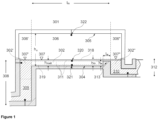
- Figure 1 shows a longitudinal section of an apparatus according to this disclosure comprising a fining vessel (301) with a middle part (311), a riser duct (308) with an upstream part (309) and a vertical duct (312) with a downstream part (310), wherein the fining vessel (301) comprises a barrier element (313) arranged on the bottom (304) of the middle part (311) located adjacent to the downstream part (310).
- the fining vessel (301) is suitable for refining a glass melt (302).
- the fining vessel has side walls (not indicated), a bottom (304), and a superstructure (305) covering the apparatus.
- the apparatus has an upstream part (309) for receiving the glass melt (302, 302') from a riser duct (308), and a downstream part (310) for purging a refined glass melt into a vertical duct (312) with downward flow.
- the apparatus is functionally divided into a middle part (311) arranged between the upstream part (309) and the downstream part (310).
- a gaseous phase (306) is provided above a surface (307) of the glass melt (302) filling the middle part (311).
- a gaseous phase (306') is above a surface (307') of a glass melt (302') in the upper section of the riser duct (308).
- the middle part (311) has a working height h melt of the glass melt (302) filling the middle part (311), a length l m , a width w m (not indicated) and a height h m .
- the fining vessel (301) comprises a barrier element (313) arranged on the bottom (304).
- the barrier element (313) has a length l w , a width w w (not indicated) and a height h w .
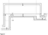
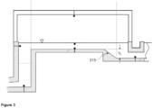
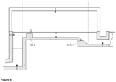
- Figures 2 , 3 and 4 only indicate the difference(s) with respect to the apparatus according to Figure 1 . All elements shown in Figure 1 are thus also present in Figures 2 , 3 and 4 .
- Figure 2 shows a longitudinal section of an apparatus according to this disclosure, wherein the fining vessel (301) comprises a barrier element (313) arranged on the bottom (304) of the middle part (311) which is located near the upstream part (309).
- the fining vessel (301) comprises a barrier element (313) arranged on the bottom (304) of the middle part (311) which is located near the upstream part (309).
- Figure 3 shows a longitudinal section of an apparatus according to this disclosure, wherein the fining vessel (301) comprises a ramp (315) which is located below the middle part (311) and before the downstream part (310).
- Figure 4 shows a longitudinal section of an apparatus according to this disclosure, wherein the fining vessel (301) comprises a barrier element (313) arranged on the bottom (304) of the middle part (311) which is located near the upstream part (309), wherein the fining vessel (301) comprises a ramp (315) which is located below the middle part (311) and before the downstream part (310).
- the fining vessel (301) comprises a barrier element (313) arranged on the bottom (304) of the middle part (311) which is located near the upstream part (309), wherein the fining vessel (301) comprises a ramp (315) which is located below the middle part (311) and before the downstream part (310).
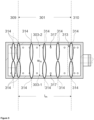
- FIG. 5 shows a top view of an apparatus according to this disclosure, wherein the apparatus is equipped with a heating burner (314) arranged within the gaseous phase (306, 306', 306").
- the heating burner (314) comprises twelve individual burners.
- the apparatus comprises electrodes, of which a pair of electrodes (317) is indicated.
- a first side wall (303-1) and a second side wall (303-2) are indicated.
- a barrier element (313) is indicated.
- a width w m of 3.6 m a width w m of 3.6 m; a length l m of 6.0 m; a length of 8.0 m including the upstream part, i.e., the riser duct, and the downstream part, i.e., the vertical duct; a working height h melt of the glass melt of 0.4 m; a total free surface of the glass melt of 28.8 m 2 ; and a height of the barrier element h w (if present) of 0.30 m. Smaller bubbles with a diameter of 500 ⁇ m or less were removed to a large extent from the glass melt in the fining vessel, i.e., the middle part. The simulation modelled physical refining effects and neglects any chemical processes which may take place.
- the minimum dwell time was found to be a relevant parameter when assessing the efficiency of the fining for a given fining vessel design at a constant melt throughput.
- a longer minimum dwell time provides for a better and more thorough refining because a larger part of the generated gas bubbles is given a chance to grow and to leave the melt.
- Kinetic processes determine the growth of the bubbles. A sufficient size of the grown bubbles is required to leave the melt within a certain time. Stated differently, the glass melt portion with the shortest minimum dwell time determines the quality of fining and hence the quality of the final glass (product).
- barrier element between 11/12 and 1.0 l m along the length l m 11.5 h
- barrier element between 0.0 and 1/12 l m along the length l m 6.5 h
- barrier element between 0.0 and 1/12 l m along the length l m and a ramp 5.5 h
- Arrangement (1) has thus proven superior because the glass melt has the largest minimum dwell time and is thus retained longest in the fining vessel thus giving a large proportion of grown gas bubbles the chance to leave the glass melt.
- the arrangements (3) and (4) provide that gas bubbles leave the glass melt in the front part of the fining vessel provided that they are already large enough and near to the glass melt surface.
Landscapes
- Chemical & Material Sciences (AREA)
- Engineering & Computer Science (AREA)
- Materials Engineering (AREA)
- Organic Chemistry (AREA)
- Physics & Mathematics (AREA)
- Thermal Sciences (AREA)
- Glass Melting And Manufacturing (AREA)
- Glass Compositions (AREA)
Priority Applications (2)
| Application Number | Priority Date | Filing Date | Title |
|---|---|---|---|
| EP23200772.4A EP4530262A1 (de) | 2023-09-29 | 2023-09-29 | Läutergefäss zum läutern einer glasschmelze und verfahren zum läutern einer glasschmelze |
| PCT/EP2024/076601 WO2025068089A1 (en) | 2023-09-29 | 2024-09-23 | A fining vessel for refining a glass melt, and method for refining a glass melt |
Applications Claiming Priority (1)
| Application Number | Priority Date | Filing Date | Title |
|---|---|---|---|
| EP23200772.4A EP4530262A1 (de) | 2023-09-29 | 2023-09-29 | Läutergefäss zum läutern einer glasschmelze und verfahren zum läutern einer glasschmelze |
Publications (1)
| Publication Number | Publication Date |
|---|---|
| EP4530262A1 true EP4530262A1 (de) | 2025-04-02 |
Family
ID=88237403
Family Applications (1)
| Application Number | Title | Priority Date | Filing Date |
|---|---|---|---|
| EP23200772.4A Pending EP4530262A1 (de) | 2023-09-29 | 2023-09-29 | Läutergefäss zum läutern einer glasschmelze und verfahren zum läutern einer glasschmelze |
Country Status (2)
| Country | Link |
|---|---|
| EP (1) | EP4530262A1 (de) |
| WO (1) | WO2025068089A1 (de) |
Citations (6)
| Publication number | Priority date | Publication date | Assignee | Title |
|---|---|---|---|---|
| US2203269A (en) * | 1938-02-14 | 1940-06-04 | Hartford Empire Co | Method of and apparatus for making glass |
| US4929266A (en) * | 1987-04-30 | 1990-05-29 | Glaverbel | Method of manufacturing glass |
| EP0864543B1 (de) * | 1997-03-13 | 2000-04-12 | BETEILIGUNGEN SORG GMBH & CO. KG | Verfahren und Glasschmelzofen zum Herstellen von hoch-schmelzenden Gläsern mit verdampfbaren Komponenten |
| US8806899B2 (en) * | 2009-01-31 | 2014-08-19 | Beteiligungen Sorg Gmbh & Co. Kg | Melting device for producing a glass melt |
| JP5630265B2 (ja) * | 2008-06-09 | 2014-11-26 | 旭硝子株式会社 | 溶融ガラスの脱泡装置 |
| CN107686226A (zh) | 2017-09-14 | 2018-02-13 | 中国建材国际工程集团有限公司 | 用于硼硅酸盐玻璃的熔窑 |
-
2023
- 2023-09-29 EP EP23200772.4A patent/EP4530262A1/de active Pending
-
2024
- 2024-09-23 WO PCT/EP2024/076601 patent/WO2025068089A1/en active Pending
Patent Citations (6)
| Publication number | Priority date | Publication date | Assignee | Title |
|---|---|---|---|---|
| US2203269A (en) * | 1938-02-14 | 1940-06-04 | Hartford Empire Co | Method of and apparatus for making glass |
| US4929266A (en) * | 1987-04-30 | 1990-05-29 | Glaverbel | Method of manufacturing glass |
| EP0864543B1 (de) * | 1997-03-13 | 2000-04-12 | BETEILIGUNGEN SORG GMBH & CO. KG | Verfahren und Glasschmelzofen zum Herstellen von hoch-schmelzenden Gläsern mit verdampfbaren Komponenten |
| JP5630265B2 (ja) * | 2008-06-09 | 2014-11-26 | 旭硝子株式会社 | 溶融ガラスの脱泡装置 |
| US8806899B2 (en) * | 2009-01-31 | 2014-08-19 | Beteiligungen Sorg Gmbh & Co. Kg | Melting device for producing a glass melt |
| CN107686226A (zh) | 2017-09-14 | 2018-02-13 | 中国建材国际工程集团有限公司 | 用于硼硅酸盐玻璃的熔窑 |
Also Published As
| Publication number | Publication date |
|---|---|
| WO2025068089A1 (en) | 2025-04-03 |
Similar Documents
| Publication | Publication Date | Title |
|---|---|---|
| EP2228348B1 (de) | Vorrichtung zur herstellung von schmelzglas und verfahren zur herstellung von schmelzglas damit | |
| CN1777563B (zh) | 使用熔融玻璃混合物生产玻璃的方法 | |
| TWI406827B (zh) | 減少玻璃中氣體雜質之裝置及方法 | |
| AU2019236452B2 (en) | Gradient fining tank for refining foamy molten glass and a method of using the same | |
| US20090235695A1 (en) | Furnace with immersed burner and overhead burner | |
| US11485664B2 (en) | Stilling vessel for submerged combustion melter | |
| AU2008261316B2 (en) | Glass melting furnace and method for melting glass | |
| CN111484233A (zh) | 一种浮法制备高硼硅玻璃的方法及装置 | |
| CN115244013B (zh) | 玻璃和玻璃陶瓷以及用于熔融和精炼其的方法和设备 | |
| US20250019287A1 (en) | Hybrid glass manufacturing furnace with electric melting, for supplying a float unit | |
| TW201840488A (zh) | 用於減少玻璃熔體表面上氣泡壽命之方法 | |
| EP2698354B1 (de) | Verfahren zur vakuum-entgasung von geschmolzenem glas, verfahren zur herstellung von geschmolzenem glas, verfahren zur herstellung eines glasartikels | |
| CN101538111A (zh) | 电熔窑精澄清方法与装置 | |
| EP4530262A1 (de) | Läutergefäss zum läutern einer glasschmelze und verfahren zum läutern einer glasschmelze | |
| JP2025531420A (ja) | エネルギー柔軟性を有するハイブリッドガラス生成炉及びガラス生成方法 | |
| US20240010539A1 (en) | Method of making high quality glass products from high viscosity melts | |
| EP4530264B1 (de) | Steigrohr für ein läutergefäss und verfahren zum läutern einer glasschmelze | |
| EP4345069A1 (de) | Gefässsystem zur herstellung und läuterung einer glasschmelze und verfahren zur herstellung und läuterung einer glasschmelze | |
| CN201458950U (zh) | 电熔窑精澄清装置 | |
| WO2025068384A1 (en) | A vessel system for producing and refining a glass melt, and method for producing and refining a glass melt | |
| RU2412120C1 (ru) | Устройство для производства базальтовых непрерывных волокон с фидерной печью | |
| EP4530261A1 (de) | Verfahren und vorrichtung zur herstellung eines glasprodukts | |
| EP4530263B1 (de) | Schmelzgefäss zum schmelzen von glas und verfahren zur herstellung einer glasschmelze | |
| EP4570764A1 (de) | Verfahren und vorrichtung zur herstellung eines glasprodukts | |
| CN121969583A (zh) | 用于澄清容器的提升管以及用于澄清玻璃熔体的方法 |
Legal Events
| Date | Code | Title | Description |
|---|---|---|---|
| STAA | Information on the status of an ep patent application or granted ep patent |
Free format text: STATUS: EXAMINATION IS IN PROGRESS |
|
| PUAI | Public reference made under article 153(3) epc to a published international application that has entered the european phase |
Free format text: ORIGINAL CODE: 0009012 |
|
| 17P | Request for examination filed |
Effective date: 20231002 |
|
| AK | Designated contracting states |
Kind code of ref document: A1 Designated state(s): AL AT BE BG CH CY CZ DE DK EE ES FI FR GB GR HR HU IE IS IT LI LT LU LV MC ME MK MT NL NO PL PT RO RS SE SI SK SM TR |
|
| P01 | Opt-out of the competence of the unified patent court (upc) registered |
Free format text: CASE NUMBER: APP_31672/2025 Effective date: 20250701 |