EP4529863A2 - Gefässverschlussvorrichtungen - Google Patents
Gefässverschlussvorrichtungen Download PDFInfo
- Publication number
- EP4529863A2 EP4529863A2 EP25158419.9A EP25158419A EP4529863A2 EP 4529863 A2 EP4529863 A2 EP 4529863A2 EP 25158419 A EP25158419 A EP 25158419A EP 4529863 A2 EP4529863 A2 EP 4529863A2
- Authority
- EP
- European Patent Office
- Prior art keywords
- distal
- loop
- primary
- vaso
- occlusive device
- Prior art date
- Legal status (The legal status is an assumption and is not a legal conclusion. Google has not performed a legal analysis and makes no representation as to the accuracy of the status listed.)
- Granted
Links
Images







Classifications
-
- A—HUMAN NECESSITIES
- A61—MEDICAL OR VETERINARY SCIENCE; HYGIENE
- A61B—DIAGNOSIS; SURGERY; IDENTIFICATION
- A61B17/00—Surgical instruments, devices or methods
- A61B17/12—Surgical instruments, devices or methods for ligaturing or otherwise compressing tubular parts of the body, e.g. blood vessels or umbilical cord
- A61B17/12022—Occluding by internal devices, e.g. balloons or releasable wires
-
- A—HUMAN NECESSITIES
- A61—MEDICAL OR VETERINARY SCIENCE; HYGIENE
- A61B—DIAGNOSIS; SURGERY; IDENTIFICATION
- A61B17/00—Surgical instruments, devices or methods
- A61B17/12—Surgical instruments, devices or methods for ligaturing or otherwise compressing tubular parts of the body, e.g. blood vessels or umbilical cord
- A61B17/12022—Occluding by internal devices, e.g. balloons or releasable wires
- A61B17/12027—Type of occlusion
- A61B17/12031—Type of occlusion complete occlusion
-
- A—HUMAN NECESSITIES
- A61—MEDICAL OR VETERINARY SCIENCE; HYGIENE
- A61B—DIAGNOSIS; SURGERY; IDENTIFICATION
- A61B17/00—Surgical instruments, devices or methods
- A61B17/12—Surgical instruments, devices or methods for ligaturing or otherwise compressing tubular parts of the body, e.g. blood vessels or umbilical cord
- A61B17/12022—Occluding by internal devices, e.g. balloons or releasable wires
- A61B17/12099—Occluding by internal devices, e.g. balloons or releasable wires characterised by the location of the occluder
- A61B17/12109—Occluding by internal devices, e.g. balloons or releasable wires characterised by the location of the occluder in a blood vessel
- A61B17/12113—Occluding by internal devices, e.g. balloons or releasable wires characterised by the location of the occluder in a blood vessel within an aneurysm
-
- A—HUMAN NECESSITIES
- A61—MEDICAL OR VETERINARY SCIENCE; HYGIENE
- A61B—DIAGNOSIS; SURGERY; IDENTIFICATION
- A61B17/00—Surgical instruments, devices or methods
- A61B17/12—Surgical instruments, devices or methods for ligaturing or otherwise compressing tubular parts of the body, e.g. blood vessels or umbilical cord
- A61B17/12022—Occluding by internal devices, e.g. balloons or releasable wires
- A61B17/12131—Occluding by internal devices, e.g. balloons or releasable wires characterised by the type of occluding device
- A61B17/1214—Coils or wires
- A61B17/12145—Coils or wires having a pre-set deployed three-dimensional shape
-
- A—HUMAN NECESSITIES
- A61—MEDICAL OR VETERINARY SCIENCE; HYGIENE
- A61B—DIAGNOSIS; SURGERY; IDENTIFICATION
- A61B17/00—Surgical instruments, devices or methods
- A61B17/12—Surgical instruments, devices or methods for ligaturing or otherwise compressing tubular parts of the body, e.g. blood vessels or umbilical cord
- A61B17/12022—Occluding by internal devices, e.g. balloons or releasable wires
- A61B17/12099—Occluding by internal devices, e.g. balloons or releasable wires characterised by the location of the occluder
- A61B17/12109—Occluding by internal devices, e.g. balloons or releasable wires characterised by the location of the occluder in a blood vessel
- A61B17/12113—Occluding by internal devices, e.g. balloons or releasable wires characterised by the location of the occluder in a blood vessel within an aneurysm
- A61B17/12118—Occluding by internal devices, e.g. balloons or releasable wires characterised by the location of the occluder in a blood vessel within an aneurysm for positioning in conjunction with a stent
-
- A—HUMAN NECESSITIES
- A61—MEDICAL OR VETERINARY SCIENCE; HYGIENE
- A61B—DIAGNOSIS; SURGERY; IDENTIFICATION
- A61B17/00—Surgical instruments, devices or methods
- A61B2017/00526—Methods of manufacturing
-
- A—HUMAN NECESSITIES
- A61—MEDICAL OR VETERINARY SCIENCE; HYGIENE
- A61B—DIAGNOSIS; SURGERY; IDENTIFICATION
- A61B17/00—Surgical instruments, devices or methods
- A61B2017/00831—Material properties
- A61B2017/00867—Material properties shape memory effect
-
- A—HUMAN NECESSITIES
- A61—MEDICAL OR VETERINARY SCIENCE; HYGIENE
- A61B—DIAGNOSIS; SURGERY; IDENTIFICATION
- A61B17/00—Surgical instruments, devices or methods
- A61B17/12—Surgical instruments, devices or methods for ligaturing or otherwise compressing tubular parts of the body, e.g. blood vessels or umbilical cord
- A61B17/12022—Occluding by internal devices, e.g. balloons or releasable wires
- A61B2017/1205—Introduction devices
Definitions
- the present disclosure relates generally to medical devices and intravascular medical procedures and, more particularly, to devices for occluding vascular defects such as aneurysms, or other anatomical cavities.
- Vaso-occlusive devices or implants are used for a wide variety of reasons, including treatment of intra-vascular aneurysms.
- An aneurysm is a dilation of a vessel, such as a blood vessel, which may pose a risk to a patient's health due to rupture, clotting, or dissection.
- rupture of an aneurysm in a patient's brain may cause a stroke, and lead to brain damage and death.
- Cerebral aneurysms may be detected in a patient, e.g., following seizure or hemorrhage, and may be treated by applying vaso-occlusive devices.
- vaso-occlusive devices include soft, helically wound coils formed by winding a platinum (or platinum alloy) wire strand about a "primary" mandrel. The coil is then wrapped around a larger, “secondary” mandrel, and heat treated to impart a secondary shape.
- a vaso-occlusive device that assumes a linear, helical primary shape when stretched for placement through the lumen of a delivery catheter, and a folded, convoluted secondary shape when released from the delivery catheter and deposited in the vasculature.
- complex three-dimensional secondary shapes can be imparted on vaso-occlusive devices and the stiffness/flexibility of vaso-occlusive devices can be modified.
- a small profile delivery catheter or "micro-catheter” In order to deliver the vaso-occlusive devices to a desired site in the vasculature, e.g., within an aneurysmal sac, it is known to first position a small profile delivery catheter or "micro-catheter" at the site using a guidewire.
- the distal end of the micro-catheter is provided, either by the attending physician or by the manufacturer, with a selected pre-shaped bend, e.g., 45°, 26°, "J", "S”, or other bending shape, depending on the particular anatomy of the patient, so that it will stay in a desired position for releasing one or more vaso-occlusive device(s) into the aneurysmal sac once the guidewire is withdrawn.
- a delivery or "pusher” assembly or “wire” is then passed through the micro-catheter until a vaso-occlusive device coupled to a distal end of the delivery assembly is extended out of the distal end opening of the micro-catheter and into the aneurysmal sac. Once in the aneurysmal sac, portions of the vaso-occlusive device may deform or bend to allow more efficient and complete packing. The vaso-occlusive device is then released or “detached" from the distal end of the delivery assembly, and the delivery assembly is withdrawn back through the micro-catheter. Depending on the particular needs of the patient, one or more additional vaso-occlusive devices may be pushed through the micro-catheter and released into the same aneurysmal sac.
- vaso-occlusive devices are typically used to visualize vaso-occlusive devices during delivery into an aneurysm, while magnetic resonance imaging (MRI) is typically used to visualize the treatment site post-procedure (e.g., a few weeks after initial treatment of the aneurysm) to ensure that the aneurysmal sac is properly occluded.
- MRI magnetic resonance imaging
- vaso-occlusive devices be constructed in a manner that enables their radiopacity during treatment of the aneurysm, while minimizing any visualization obscuring artifacts created during the post-procedure MRI (i.e., being MRI-compatible). It is also preferable that such vaso-occlusive devices be "soft" (i.e., be laterally flexible or conformable), and thus atraumatic, to prevent rupturing of the delicate tissues of the aneurysm.
- vaso-occlusive devices be chronically retained within the aneurysm.
- aneurysms with larger mouths commonly known as “wide neck aneurysms”
- small aneurysms e.g., aneurysm having diameters less than about 7 mm or even smaller such as less than about 5 mm
- Fig. 1 shows one example of herniation during an initial deployment of a vaso-occlusive coil.
- FIG. 4 depicts a jailing technique using a stent.
- the stent is placed and expanded around the neck of the aneurysm to block the coils from exiting the aneurysm sac. Similar to the balloon activated catheter, the stent also risks the stent pushing the tip of the catheter into the dome of the aneurysm and rupturing the aneurysm.
- Fig. 5 depicts another placement technique for implanting a vaso-occlusive device called "recrossing.” In this technique, the delivery catheter extends through an opening in the stent.
- the stent technique prevents the coils from herniating out of the aneurysm sac.
- due to inherent unpredictability of positioning the delivery catheter through an opening of the stent there is a risk that manipulation of the delivery catheter to direct and position the delivery catheter can cause the catheter tip to push into the dome thereby rupturing the aneurysm.
- vaso-occlusive coils have been developed which provide more neck coverage and shape stability to effectively "frame" an aneurysm.
- the three-dimensional shapes of current vaso-occlusive devices are either not conducive to framing or are prone to herniation during deployment into an aneurysm. Small aneurysms are best treated with as few coils as possible and current vaso-occlusive devices are not able to balance shape stability and softness as a standalone unit.
- the shapes and configuration of current vaso-occlusive devices result in a directly proportional relationship between shape stability and softness.
- the softer the device i.e., the less resistant to deformation from an external force
- the less stable the device i.e., the less soft the device, the more stable the shape of the vaso-occlusive device.
- a softer coil is less likely to rupture an aneurysm but is not able to retain its shape such that it is more prone to herniation out of the aneurysm during deployment and/or retention.
- a stiffer coil is better able to retain its shape and frame the aneurysm, but imparts higher stresses on the aneurysm wall, creating high risk of rupturing the aneurysm, especially small aneurysms with a high rupture risk.
- the initial distal loops e.g., first and second loops
- the initial distal loops have a higher likelihood of herniating out of the aneurysm due to subsequent loops pushing them out during deployment.
- an implant device 1000 includes a coil formed of a wire having a primary configuration having a proximal end 1012 and a distal end 1014 and a secondary configuration in a relaxed, unconstrained condition.
- the secondary configuration includes a plurality of helical loops 1004 including a distal most loop having a proximal end and a distal end and a perimeter length from the proximal end to the distal end.
- the implant device 1000 also has a transition 1006 connected to the distal end 1014 of helical section 1004.
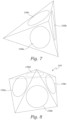
- vaso-occlusive device having a specially designed distal anchoring loop having a substantially triangular shape, an overall length of 25% to 75% of the perimeter length of the distal-most loop and/or that the distal anchoring loop is positioned within a projection of the distal-most loop. Accordingly, there is a need for vaso-occlusive devices which can alleviate the issues of herniation during placement and retention and provide effective framing of the aneurysm, and at the same time have a sufficiently soft and pliable structure that will not rupture the aneurysm, especially small, wide-necked aneurysms.
- vaso-occlusive devices which can alleviate the issues of herniation during placement and retention and provide effective framing of the aneurysm, and at the same time have a sufficiently soft and pliable structure that will not rupture the aneurysm, especially small, wide-necked aneurysms.
- the object of the present invention is to satisfy these needs.
- vaso-occlusive device which has a design as defined by the attached claims.
- vaso-occlusive device 100 an example of a vaso-occlusive device 100, as disclosed herein, is illustrated.
- the examples of vaso-occlusive devices are described in detail herein as vaso-occlusive devices for occluding aneurysms, with the understanding that the devices are not limited to being configured for deployment into an aneurysm, but may be sized and configured for occluding any suitable anatomical cavity.
- the devices are not limited to being occlusive devices, but may be any suitable medical device, such as a thrombectomy device, stent retriever, embolic filter, stent delivery system, other implantation device, guidewire, intravascular device, or the like.
- FIG. 6 depicts the vaso-occlusive device 100 in its secondary configuration in a relaxed, unconstrained condition.
- FIG. 6 shows the vaso-occlusive device 100 when there are no external forces exerting on the vaso-occlusive device 100.
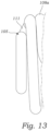
- the secondary configuration of the vaso-occlusive device 100 has a primary portion 104, a base portion 106, and a distal anchoring loop 105.
- the primary portion 104 is distal to the body portion 106, and the distal anchoring loop 105 is distal to the primary portion 104.
- distal and proximal as used herein are relative to the vaso-occlusive device 100 as it is intended to be deployed, wherein the term “distal” refers to being situated toward the end of the device 100 which is inserted first, and “proximal” refers to being situated toward the end of the device 100 which is inserted last.
- the vaso-occlusive 100 comprises a coil formed of a wire 102 having a primary configuration in a constrained configuration.
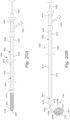
- the constrained configuration may be an elongate, helical coil when the wire 102 is constrained within a delivery catheter (see FIG. 20A ).
- the primary shape has a longitudinal length between 1 cm to 70 cm.
- the wire 102 is made from any suitable material, but typically comprises a radiopaque, shape memory material, such as the platinum group metals, including platinum, rhodium, palladium, and rhenium, as well as tungsten, gold, silver, tantalum, and alloys of these metals.
- the primary portion 104 includes a plurality of primary loops 108 wound from the wire 102.
- the primary portion 104 includes three primary loops 108a, 108b, and 108c.
- the first primary loop 108a (also referred to as the "distal primary loop") is the distal-most primary loop 108
- the second primary loop 108b is just proximal of the first primary loop 108a
- the third primary loop 108c is just proximal of the second primary loop 108b (i.e., it is the proximal-most primary loop 108).
- the primary loops 108 are connected end to end, such that a proximal end of the first primary loop 108a is connected to the distal end of the second primary loop 108b, and the proximal end of the second primary loop 108b is connected to the distal end of the third primary loop 108c.
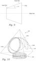
- the post has a diameter which tapers outwardly from the inner part of the post to the outer part of the post, as depicted in FIG. 8 .
- the angle 114 of the post taper defines the angle of the taper of the primary loop 108 in the secondary configuration of the vaso-occlusive device 100. Due to the outwardly tapering diameter, the loops or turns of each of the primary loops 108 is inward facing. In other words, the surface of the loops faces inward toward the geometric interior of the pyramidal shape of the primary portion 104.
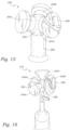
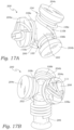
- FIG. 16 shows a mandrel 210 which is configured to make a vaso-occlusive device 100 comprising a primary portion 104 having a square pyramid shape.
- the mandrel 210 is same or substantially similar to the mandrel 200, except that the mandrel 210 has four primary loop posts 204 evenly, angularly spaced around the central, spherical member 202.
- the delivery catheter 406 may also have one or more ports 422 in fluid communication with the lumen 420 for introducing into, or removing fluids from, the sheath body 414.
- the sheath body 414 may be composed of suitable polymeric materials, metals and/or alloys, such as polyethylene, stainless steel or other suitable biocompatible materials or combinations thereof.
- the proximal portion 416 may include a reinforcement layer, such as a braided layer or coiled layer to enhance the pushability of the sheath body 414.
- the sheath body 414 may include a transition region between the proximal portion 416 and the distal portion 418.
- the vaso-occlusive device 100 may be any of the vaso-occlusive device 100 disclosed herein, having any one or more of the features and aspects described herein.
- the vaso-occlusive assembly 404 also comprises a pusher member 410.
- the pusher member 410 is configured to be slidably received within the lumen 420 of the delivery catheter 406.
- the pusher member 410 has a proximal portion 450, which typically extends proximal of the proximal portion 416 of the delivery catheter 406, and a distal portion 452 which is detachably coupled to the proximal end of the vaso-occlusive device 100 via the detachment device 412.
- the detachment device 412 provides a detachable connection between the pusher member 410 and the vaso-occlusive device 100.
- the detachment device 412 may comprise an electrolytically detachment, mechanical connector, heat activated detachment, dissolving detachment, or other mechanical, thermal and hydraulic mechanism.
- the detachment device 412 may be an electrolytically degradable segment for electrolytically decoupling the vaso-occlusive device 100 from the pusher member 410.
- the optional guidewire 408 of the delivery assembly 402 has a proximal end 444 and a distal end 446.
- the delivery catheter 406 is advanced over the guidewire 408 with the guidewire 408 disposed within the lumen 420 of the delivery catheter 406.
- the guidewire 408 extends through only a distal portion of the delivery catheter 406, such as a rapid-exchange lumen.
- the guidewire 408 is typically used by first advancing the guidewire 408 through the patient's vasculature to the target insertion site (e.g., the neck 448 of an aneurysm to be filled by the vaso-occlusive device 100, see FIGS. 21-24 ), and then advancing the delivery catheter 406 over the guidewire 408 to the target insertion site.
- the target insertion site e.g., the neck 448 of an aneurysm to be filled by the vaso-occlusive device 100, see FIGS. 21-24
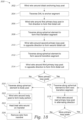
- FIGS. 21-25 an exemplary method 500 of using the vaso-occlusive system 200 is illustrated to deploy the vaso-occlusive device 100 into an anatomical cavity will now be described.
- the method 500 will be described with respect to deploying the vaso-occlusive device 100 into an aneurysmal sac 440, as an example.
- the method 500 is not limited to deploying the vaso-occlusive device 100 into an aneurysmal sac 440, but may be used to deploy the vaso-occlusive device 100, or another medical device as disclosed herein, into any suitable anatomical cavity which is accessible via a patient's vasculature. Referring to the flow chart of FIG. 25 and FIG.
- the guidewire 408 is inserted into the patient's vasculature 442 and is advanced to the target insertion site, namely the aneurysmal sac 440.
- the use of the guidewire 408 is optional, and is not required in the method 500 of using the vaso-occlusive system 200 to deploy the vaso-occlusive device 100.
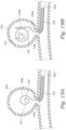
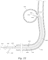
- the delivery catheter 406 of the delivery assembly 402 is advanced over the guidewire 408 until it is positioned with the open distal end 418 adjacent or within the aneurysmal neck 448 of the aneurysm 440, as shown in FIG. 23 .
- the guidewire 408 is pulled out of the delivery catheter 406 leaving the delivery catheter 406 in position.
- the vaso-occlusive assembly 404 is inserted into the delivery catheter 406 of the delivery assembly 402 and advanced within the delivery catheter 406 to position the distal end of the vaso-occlusive device 100 adjacent the distal portion 418 of the delivery catheter 406, as shown in FIG. 23 .
- the proximal portion 450 of the pusher member 410 remains proximal and outside of the proximal portion 416 of the delivery catheter 406.
- the vaso-occlusive device 100 Prior to inserting the vaso-occlusive device 100 into the delivery catheter 406, the vaso-occlusive device 100 may be pre-installed in a sheath such that the vaso-occlusive device 100 is in its constrained, delivery configuration (primary configuration).
- the vaso-occlusive device 100 is then inserted into the delivery catheter 406 by placing a distal end of the sheath in abutment with the proximal end 416 of the delivery catheter 406 and extruding the vaso-occlusive device 406 from the sheath into the delivery catheter 406 such that the vaso-occlusive device 100 remains in its delivery configuration within the delivery catheter 206.
- the vaso-occlusive device 100 is pushed through the lumen 420 of the delivery catheter 406 and distally out of the delivery catheter 406 by pushing on the proximal portion 450 of the pusher member 412.
- the primary portion 104 is advanced through the aneurysmal neck 448 and into the aneurysmal sac 440, the distal portion of the vaso-occlusive device 100 in its delivery configuration (primary configuration) expands into the secondary configuration (deployed configuration), and the primary loops 108 of the primary portion 104 are formed within the aneurysmal sac 440, as depicted in FIG.
- the distal anchoring loop 105 is deployed into the aneurysmal sac 440 and assumes its triangular shape in the secondary configuration.
- the primary loops 108 of the vaso-occlusive device 100 in their delivery configuration (primary configuration) expand into the secondary configuration (deployed configuration) forming the primary portion 104.
- the base portion 106 is inserted and assumes it secondary configuration within aneurysmal sac 440.
- the detachment device 412 is actuated, activated or otherwise operated to detach the vaso-occlusive device 100 from the pusher-member 410.
- the pusher member 410 is removed from the patient's vasculature 442 by withdrawing it out through the delivery catheter 406. If the single vaso-occlusive device 100 is sufficient to fill and occlude the aneurysm sac 440, then the method 500 proceeds to step 520 in which the delivery catheter 406 is removed from the patient's vasculature 442.
- steps 508-516 are repeated to deliver a sufficient number of vaso-occlusive devices 100 to fill and occlude the aneurysmal sac 440.
- the delivery catheter 406 is removed at step 520.
Landscapes
- Health & Medical Sciences (AREA)
- Surgery (AREA)
- Life Sciences & Earth Sciences (AREA)
- Heart & Thoracic Surgery (AREA)
- Molecular Biology (AREA)
- Vascular Medicine (AREA)
- Engineering & Computer Science (AREA)
- Biomedical Technology (AREA)
- Reproductive Health (AREA)
- Medical Informatics (AREA)
- Nuclear Medicine, Radiotherapy & Molecular Imaging (AREA)
- Animal Behavior & Ethology (AREA)
- General Health & Medical Sciences (AREA)
- Public Health (AREA)
- Veterinary Medicine (AREA)
- Neurosurgery (AREA)
- Surgical Instruments (AREA)
- Prostheses (AREA)
Applications Claiming Priority (3)
| Application Number | Priority Date | Filing Date | Title |
|---|---|---|---|
| US202163278379P | 2021-11-11 | 2021-11-11 | |
| PCT/US2022/078932 WO2023086738A1 (en) | 2021-11-11 | 2022-10-28 | Vaso-occlusive devices and methods for making and using same |
| EP22813069.6A EP4319653B1 (de) | 2021-11-11 | 2022-10-28 | Vasookklusive vorrichtungen |
Related Parent Applications (2)
| Application Number | Title | Priority Date | Filing Date |
|---|---|---|---|
| EP22813069.6A Division EP4319653B1 (de) | 2021-11-11 | 2022-10-28 | Vasookklusive vorrichtungen |
| EP22813069.6A Division-Into EP4319653B1 (de) | 2021-11-11 | 2022-10-28 | Vasookklusive vorrichtungen |
Publications (3)
| Publication Number | Publication Date |
|---|---|
| EP4529863A2 true EP4529863A2 (de) | 2025-04-02 |
| EP4529863A3 EP4529863A3 (de) | 2025-06-04 |
| EP4529863B1 EP4529863B1 (de) | 2026-04-15 |
Family
ID=84327124
Family Applications (2)
| Application Number | Title | Priority Date | Filing Date |
|---|---|---|---|
| EP25158419.9A Active EP4529863B1 (de) | 2021-11-11 | 2022-10-28 | Gefässverschlussvorrichtungen |
| EP22813069.6A Active EP4319653B1 (de) | 2021-11-11 | 2022-10-28 | Vasookklusive vorrichtungen |
Family Applications After (1)
| Application Number | Title | Priority Date | Filing Date |
|---|---|---|---|
| EP22813069.6A Active EP4319653B1 (de) | 2021-11-11 | 2022-10-28 | Vasookklusive vorrichtungen |
Country Status (6)
| Country | Link |
|---|---|
| US (2) | US12076021B2 (de) |
| EP (2) | EP4529863B1 (de) |
| JP (2) | JP7423865B2 (de) |
| CN (2) | CN117860330A (de) |
| ES (1) | ES3024611T3 (de) |
| WO (1) | WO2023086738A1 (de) |
Families Citing this family (2)
| Publication number | Priority date | Publication date | Assignee | Title |
|---|---|---|---|---|
| WO2023091852A1 (en) * | 2021-11-19 | 2023-05-25 | Stryker Corporation | Vaso-occlusive devices and methods for making and using same |
| CN118512228B (zh) * | 2024-05-14 | 2025-11-11 | 北京巨源仁通医疗科技有限公司 | 一种封堵器 |
Citations (2)
| Publication number | Priority date | Publication date | Assignee | Title |
|---|---|---|---|---|
| US4994069A (en) | 1988-11-02 | 1991-02-19 | Target Therapeutics | Vaso-occlusion coil and method |
| US20150119920A1 (en) | 2006-03-13 | 2015-04-30 | Pneumrx, Inc. | Genetically-Associated Chronic Obstructive Pulmonary Disease Treatment |
Family Cites Families (6)
| Publication number | Priority date | Publication date | Assignee | Title |
|---|---|---|---|---|
| US5649949A (en) * | 1996-03-14 | 1997-07-22 | Target Therapeutics, Inc. | Variable cross-section conical vasoocclusive coils |
| US7029486B2 (en) * | 2000-09-26 | 2006-04-18 | Microvention, Inc. | Microcoil vaso-occlusive device with multi-axis secondary configuration |
| JP2003230564A (ja) * | 2002-02-12 | 2003-08-19 | Piolax Medical Device:Kk | 血管閉塞具 |
| US11224437B2 (en) * | 2014-01-14 | 2022-01-18 | Penumbra, Inc. | Soft embolic implant |
| CN108882983A (zh) * | 2016-05-13 | 2018-11-23 | 柯惠有限合伙公司 | 动脉瘤治疗线圈 |
| US20190015107A1 (en) * | 2017-07-13 | 2019-01-17 | Spartan Micro, Inc. | Vaso-Occlusive Device and Method |
-
2022
- 2022-10-28 EP EP25158419.9A patent/EP4529863B1/de active Active
- 2022-10-28 JP JP2023545962A patent/JP7423865B2/ja active Active
- 2022-10-28 ES ES22813069T patent/ES3024611T3/es active Active
- 2022-10-28 CN CN202410199002.1A patent/CN117860330A/zh active Pending
- 2022-10-28 CN CN202280008212.7A patent/CN116648201B/zh active Active
- 2022-10-28 EP EP22813069.6A patent/EP4319653B1/de active Active
- 2022-10-28 WO PCT/US2022/078932 patent/WO2023086738A1/en not_active Ceased
-
2023
- 2023-06-15 US US18/336,011 patent/US12076021B2/en active Active
-
2024
- 2024-01-17 JP JP2024005003A patent/JP7630022B2/ja active Active
- 2024-07-19 US US18/777,980 patent/US20240374261A1/en active Pending
Patent Citations (2)
| Publication number | Priority date | Publication date | Assignee | Title |
|---|---|---|---|---|
| US4994069A (en) | 1988-11-02 | 1991-02-19 | Target Therapeutics | Vaso-occlusion coil and method |
| US20150119920A1 (en) | 2006-03-13 | 2015-04-30 | Pneumrx, Inc. | Genetically-Associated Chronic Obstructive Pulmonary Disease Treatment |
Also Published As
| Publication number | Publication date |
|---|---|
| JP7630022B2 (ja) | 2025-02-14 |
| EP4319653A1 (de) | 2024-02-14 |
| WO2023086738A1 (en) | 2023-05-19 |
| ES3024611T3 (en) | 2025-06-04 |
| EP4529863A3 (de) | 2025-06-04 |
| JP2024045240A (ja) | 2024-04-02 |
| JP2024502497A (ja) | 2024-01-19 |
| CN117860330A (zh) | 2024-04-12 |
| US12076021B2 (en) | 2024-09-03 |
| CN116648201B (zh) | 2024-03-26 |
| EP4319653B1 (de) | 2025-03-26 |
| EP4529863B1 (de) | 2026-04-15 |
| JP7423865B2 (ja) | 2024-01-29 |
| CN116648201A (zh) | 2023-08-25 |
| US20230329720A1 (en) | 2023-10-19 |
| US20240374261A1 (en) | 2024-11-14 |
Similar Documents
| Publication | Publication Date | Title |
|---|---|---|
| US20200000477A1 (en) | Embolization Plug | |
| US20240374261A1 (en) | Vaso-occlusive devices and methods for making and using same | |
| JP7512497B2 (ja) | 血管閉塞デバイス | |
| US9138232B2 (en) | Aneurysm occlusion by rotational dispensation of mass | |
| US20180317933A1 (en) | Devices and Methods for Treatment of Endovascular and Non-Endovascular Defects in Humans | |
| US12127743B2 (en) | Inverting braided aneurysm implant with dome feature | |
| US20240299035A1 (en) | Vaso-occlusive devices and methods for making and using same | |
| JP2023539289A (ja) | 動脈瘤閉塞装置、動脈瘤閉塞治療装置、および動脈瘤閉塞システム | |
| US20250255611A1 (en) | Vaso-occlusive devices for occluding blood vessels and methods for making and using same | |
| EP4398814B1 (de) | Gefässverschlussvorrichtung | |
| CN116035640A (zh) | 医用植入物及制备方法 |
Legal Events
| Date | Code | Title | Description |
|---|---|---|---|
| PUAI | Public reference made under article 153(3) epc to a published international application that has entered the european phase |
Free format text: ORIGINAL CODE: 0009012 |
|
| STAA | Information on the status of an ep patent application or granted ep patent |
Free format text: STATUS: THE APPLICATION HAS BEEN PUBLISHED |
|
| AC | Divisional application: reference to earlier application |
Ref document number: 4319653 Country of ref document: EP Kind code of ref document: P |
|
| AK | Designated contracting states |
Kind code of ref document: A2 Designated state(s): AL AT BE BG CH CY CZ DE DK EE ES FI FR GB GR HR HU IE IS IT LI LT LU LV MC ME MK MT NL NO PL PT RO RS SE SI SK SM TR |
|
| PUAL | Search report despatched |
Free format text: ORIGINAL CODE: 0009013 |
|
| AK | Designated contracting states |
Kind code of ref document: A3 Designated state(s): AL AT BE BG CH CY CZ DE DK EE ES FI FR GB GR HR HU IE IS IT LI LT LU LV MC ME MK MT NL NO PL PT RO RS SE SI SK SM TR |
|
| RIC1 | Information provided on ipc code assigned before grant |
Ipc: A61B 17/12 20060101AFI20250430BHEP |
|
| STAA | Information on the status of an ep patent application or granted ep patent |
Free format text: STATUS: REQUEST FOR EXAMINATION WAS MADE |
|
| 17P | Request for examination filed |
Effective date: 20250722 |
|
| GRAP | Despatch of communication of intention to grant a patent |
Free format text: ORIGINAL CODE: EPIDOSNIGR1 |
|
| STAA | Information on the status of an ep patent application or granted ep patent |
Free format text: STATUS: GRANT OF PATENT IS INTENDED |
|
| INTG | Intention to grant announced |
Effective date: 20251120 |
|
| GRAS | Grant fee paid |
Free format text: ORIGINAL CODE: EPIDOSNIGR3 |
|
| GRAA | (expected) grant |
Free format text: ORIGINAL CODE: 0009210 |
|
| STAA | Information on the status of an ep patent application or granted ep patent |
Free format text: STATUS: THE PATENT HAS BEEN GRANTED |
|
| AC | Divisional application: reference to earlier application |
Ref document number: 4319653 Country of ref document: EP Kind code of ref document: P |
|
| AK | Designated contracting states |
Kind code of ref document: B1 Designated state(s): AL AT BE BG CH CY CZ DE DK EE ES FI FR GB GR HR HU IE IS IT LI LT LU LV MC ME MK MT NL NO PL PT RO RS SE SI SK SM TR |
|
| REG | Reference to a national code |
Ref country code: CH Ref legal event code: F10 Free format text: ST27 STATUS EVENT CODE: U-0-0-F10-F00 (AS PROVIDED BY THE NATIONAL OFFICE) Effective date: 20260415 |