EP4527650A1 - Ouvrant coulissant motorisé d'un véhicule - Google Patents
Ouvrant coulissant motorisé d'un véhicule Download PDFInfo
- Publication number
- EP4527650A1 EP4527650A1 EP24199872.3A EP24199872A EP4527650A1 EP 4527650 A1 EP4527650 A1 EP 4527650A1 EP 24199872 A EP24199872 A EP 24199872A EP 4527650 A1 EP4527650 A1 EP 4527650A1
- Authority
- EP
- European Patent Office
- Prior art keywords
- sliding opening
- motorized sliding
- motorized
- protective tray
- power cable
- Prior art date
- Legal status (The legal status is an assumption and is not a legal conclusion. Google has not performed a legal analysis and makes no representation as to the accuracy of the status listed.)
- Pending
Links
Images

Classifications
-
- B—PERFORMING OPERATIONS; TRANSPORTING
- B60—VEHICLES IN GENERAL
- B60J—WINDOWS, WINDSCREENS, NON-FIXED ROOFS, DOORS, OR SIMILAR DEVICES FOR VEHICLES; REMOVABLE EXTERNAL PROTECTIVE COVERINGS SPECIALLY ADAPTED FOR VEHICLES
- B60J5/00—Doors
- B60J5/04—Doors arranged at the vehicle sides
- B60J5/06—Doors arranged at the vehicle sides slidable; foldable
-
- B—PERFORMING OPERATIONS; TRANSPORTING
- B60—VEHICLES IN GENERAL
- B60R—VEHICLES, VEHICLE FITTINGS, OR VEHICLE PARTS, NOT OTHERWISE PROVIDED FOR
- B60R16/00—Electric or fluid circuits specially adapted for vehicles and not otherwise provided for; Arrangement of elements of electric or fluid circuits specially adapted for vehicles and not otherwise provided for
- B60R16/02—Electric or fluid circuits specially adapted for vehicles and not otherwise provided for; Arrangement of elements of electric or fluid circuits specially adapted for vehicles and not otherwise provided for electric constitutive elements
- B60R16/03—Electric or fluid circuits specially adapted for vehicles and not otherwise provided for; Arrangement of elements of electric or fluid circuits specially adapted for vehicles and not otherwise provided for electric constitutive elements for supply of electrical power to vehicle subsystems or for
Definitions
- the present invention relates to the field of motorized openings for vehicles.
- the present invention relates more particularly to the architecture of such openings making it possible to electrically connect either an electrical power source to a drive motor arranged in the opening or a locking/unlocking control device to a drive motor arranged on the body of the vehicle.
- Some motor vehicles include a sliding opening, such opening being able to be arranged on one side only, on each side or at the rear of a vehicle body.
- openings are configured to slide in a first direction so as to generate an opening of the opening and in a second direction so as to cause a closing of the opening.
- the movement of the opening in one direction or the other can be controlled in a motorized manner by the user by remotely activating one or more motors driving the opening according to said movement.
- At least the motor(s) involved in moving the opening require to be supplied with electricity from an electrical energy storage means arranged in the vehicle.
- said motor(s) are connected to the electrical energy storage means by an electrical power supply cable.
- This power cable must be able to accompany the movement of the opening relative to the vehicle.
- this housing is traditionally made by stamping the interior panel, which results in significant space consumption.
- the present invention falls within this context and proposes to overcome at least some of the drawbacks of the prior art and in particular to propose an architecture of a motorized opening making it possible to protect a power cable while minimizing the size of the opening to protect said power cable.
- the present invention relates to a motorized sliding opening intended to equip a vehicle, the motorized sliding opening comprising an outer panel, an inner panel, at least a portion of a drive means configured to allow the opening and/or closing of the motorized sliding opening, said drive means comprising in particular a motorization making the sliding opening motorized and at least one power cable arranged in the volume of the motorized sliding opening, the at least one power cable being configured to allow the supply of electrical energy to at least one drive motor included in the motorized sliding opening and/or an electrical control of the drive means comprising at least one drive motor arranged on the body of the vehicle on which the motorized sliding opening is intended to be slidably mounted, the inner panel comprising a cutout in which a protective tray is housed, the protective tray forming a receiving housing in which the at least one power cable is arranged, the protective tray being separate from the inner panel and secured to said inner panel.
- the motorized sliding opening is a door of a vehicle, for example a car, capable of moving along a guide rail, made on the vehicle or on the motorized sliding opening, to allow or prohibit access to the vehicle.
- the motorized sliding opening can be a side door or even a rear door of a utility vehicle since the opening and/or closing of the motorized sliding opening is carried out by sliding movement along a guide means.
- the drive means comprises at least one drive motor for motorizing the opening and/or closing of the motorized sliding opening.
- the power cable makes it possible to directly activate the at least one drive motor or an electrical control of said drive motor to enable the movement of the motorized sliding opening.
- the motorized sliding opening is formed of at least one outer panel and one inner panel.
- the outer panel forms the bodywork element of the vehicle in direct contact with the environment outside the vehicle.
- This exterior body panel features a structure that allows the motorized sliding door to withstand external impacts and aggressions.
- the interior panel forms the vehicle element for the vehicle's passenger compartment.
- the volume of the motorized sliding opening is defined between the outer panel and the inner panel. It is understood that the power cable is arranged in the volume of the motorized sliding opening so that when the motorized sliding opening is in a closed position, the power cable is housed in the motorized sliding opening between the outer panel and the inner panel.
- the cutout of the inner panel is made so that the latter has dimensions complementary to those of the protective tray to accommodate the protective tray in said cutout while minimizing the space between the protective tray and the inner panel.
- the cutout of the inner panel is adjusted to allow the latter to receive the protective tray with the walls defining the protective tray which are as close as possible to the edges of the inner panel delimiting the cutout.
- the protective tray is secured to the interior panel and is intended to house a power cable for electrically connecting the motorized sliding opening.
- This power cable is able to accompany the motorized sliding opening during the movement of the motorized sliding opening between an open position and a closed position.
- the power cable accompanies, during the movement of the motorized sliding opening between its open position and its closed position, the movement of the motorized sliding opening while remaining at least partly housed in the protective tray.
- the power cable is able to exit the protective tray to accompany the movement of the motorized sliding opening. It is understood that at least a portion of the power cable is continuously connected to an element of the motorized sliding opening.
- the protective tray forms a housing, said housing being arranged in a thickness, or volume, of the motorized sliding opening defined between the outer panel and the inner panel.
- the outer panel and the inner panel with at least one of the panels having a non-planar shape, are secured to each other, particularly on their periphery, to generate a sealed space inside the opening between the outer panel and the inner panel. It is understood that the thickness of the motorized sliding opening, within which the protective tray is positioned, is formed from the thickness of the outer panel, the thickness of the inner panel and the space between the inner panel and the outer panel.
- the housing is arranged in the volume of the motorized sliding opening defined between the exterior panel and the interior panel.
- the housing is delimited at least in part by a bottom wall and by a side wall, the side wall and the bottom wall forming a first angle with each other of between 90° and 120°.
- a first angle between the side wall, or lateral wall, and the bottom wall makes it possible to limit the size of the protective tray within the motorized sliding opening.
- a protective tray inserted in an opening formed by cutting the interior panel, rather than directly by stamping the interior panel it is possible to get as close as possible to a right-angled design, which limits the angle between the bottom wall and the side wall and which makes it possible to limit the space taken up by the protective tray in the motorized sliding opening.
- the housing of the protective tray is delimited by a peripheral edge of the protective tray, the peripheral edge being secured to the interior panel.
- the peripheral edge extends perpendicularly the side wall at an end opposite to that connected to the bottom wall and it extends this side wall towards the outside of the protective tray.
- the housing has a shape that matches the shape of the power cable.
- the housing has dimensions allowing it to match the shape of the power cable.
- the power cable is entirely housed in the housing formed by the protective tray.
- the peripheral edge is in contact with the interior panel by a flat support.
- peripheral edge extends in a plane parallel to the plane in which the portion of the inner panel in contact with the peripheral edge is inscribed.
- the protective tray is secured to the outer panel at a portion of the protective tray distinct from the peripheral edge.
- the portion of the protective tray at which the protective tray is secured to the outer panel is arranged opposite the housing.
- This portion of the protective tray makes it possible to increase the rigidity of the motorized sliding opening by generating a connection point between the outer panel and the inner panel via the protective tray. More specifically, this portion of the protective tray forms the bottom wall of the protective tray.
- the invention also relates to a motor vehicle comprising a motorized sliding opening conforming to at least some of the characteristics, the motor vehicle comprising a guide rail in which the motorized sliding opening is able to move between an open position and a closed position, the protective tray of the motorized sliding opening being arranged directly opposite the guide rail.
- the arrangement of the motorized sliding opening opposite the guide rail can be carried out opposite a sill, that is to say opposite a protective element of the underbody of the vehicle.
- Such an arrangement of the protective tray at the level of the guide rail makes it possible to ensure better protection of the power cable, in particular in the event of an impact coming from outside the vehicle.
- variants of the invention may be combined with each other in various combinations, provided that they are not incompatible or mutually exclusive.
- variants of the invention may be conceived comprising only a selection of features described below in isolation from the other features described, if this selection of features is sufficient to confer a technical advantage or to differentiate the invention from the state of the art.
- a longitudinal direction corresponds to a direction of advance of a vehicle equipped with the sliding opening motorized, this longitudinal direction being parallel to a longitudinal axis L of a reference L, V, T shown in the figures.
- a transverse direction corresponds to a direction perpendicular, in a plane parallel to the road on which the vehicle is traveling, to the direction of travel of the vehicle equipped with the motorized sliding opening, this transverse direction being parallel to a transverse axis T of the reference L, V, T and this transverse axis T being perpendicular to the longitudinal axis L.
- a vertical direction corresponds to a direction parallel to a vertical axis V of the reference L, V, T, this vertical axis V being perpendicular to the longitudinal axis L and to the transverse axis T.
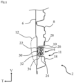
- FIG. 1 illustrates a motorized sliding opening 2 according to one embodiment of the invention.
- the motorized sliding opening 2 is intended to equip a vehicle, and more particularly a motor vehicle.
- This motorized sliding opening 2 forms, in the embodiment shown, a side door of a motor vehicle.
- the motorized sliding opening 2 is slidably mounted relative to the vehicle so as to be able to move on the one hand, in a first direction to reach an open position allowing, for example, a user to enter or exit the vehicle and on the other hand, in a second direction to reach a closed position preventing, for example, a user from entering or exiting the vehicle. It is understood that the first direction and the second direction are in the same direction.
- the movement of the motorized sliding opening 2 is allowed, as an illustrative and non-limiting example of the invention, by rollers secured to the motorized sliding opening 2 circulating in at least one guide rail produced on the motor vehicle. It is understood that the rollers are linked to the motorized sliding opening 2 and cooperate with the at least one guide rail to keep the motorized sliding opening 2 secured to the motor vehicle.
- the movement of the motorized sliding opening 2 is controlled by means of at least one drive motor configured to move the motorized sliding opening 2 relative to the vehicle between the open position and the closed position.
- the movement of the motorized sliding opening 2 by the at least one drive motor can be achieved, as illustrative and non-limiting examples of the invention, by controlling the movement of at least one roller in the guide rail or by the movement of a toothed wheel secured either to the motorized sliding opening 2, in a rack secured to the motor vehicle, or to the body of the vehicle, in a rack secured to the motorized sliding opening.
- the at least one drive motor is an electric motor supplied with electrical energy from an energy storage means.
- the electrical energy storage means is arranged in the motor vehicle and is connected to the at least one drive motor by a power cable 4, visible in more detail in the figures 2 to 5
- the means of storing electrical energy can, for example, be the batteries of the motor vehicle.
- the motorized sliding opening 2 comprises an exterior panel 6 forming the part of the motorized sliding opening 2 intended to be in contact with the environment outside the motor vehicle and an interior panel 8 secured to the exterior panel 6 and forming the part of the motorized sliding opening 2 intended to be in contact with the environment inside the passenger compartment of the motor vehicle.
- the motorized sliding opening 2 comprises a protective tray 10 in which the power cable 4 is arranged.
- the protective tray 10 is secured to the interior panel 8 and forms a housing 11 arranged in a volume, or a thickness, of the motorized sliding opening 2 delimited between the exterior panel 6 and the interior panel 8.
- the power cable 4 is, as will be described in more detail in the description which follows, able to move in the protective tray 10 so as to accompany the motorized sliding opening 2 during its movement between its open position and its closed position.
- the interior panel 8 comprises a cutout forming an opening at dimensions of the protective tray 10. This cutout forms an empty portion within the interior panel 8 allowing the protective tray 10 to be inserted into the volume of the motorized sliding opening 2.
- the motorized sliding opening 2 comprises a boss 12 arranged against the exterior panel 6.
- This boss 12 and the protective tray 10 are arranged opposite each other so that the boss 12 helps to protect the protective tray 10, for example from an impact external to the vehicle and which could damage the protective tray 10.
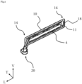
- FIG. 2 represents very schematically the protective tray 10 in which the power cable 4 is housed. More specifically, the protective tray 10 extends in a main longitudinal elongation direction between a first end 14 and a second end 16. The housing 11 extends within the protective tray 10 between the first end 14 and the second end 16 parallel to the main longitudinal elongation direction of the protective tray 10.
- the protective tray 10 comprises a peripheral edge 18 which extends over the entire circumference of the protective tray 10, radially delimiting the opening of the housing 11.
- the peripheral edge 18 extends, in the embodiment shown, in a plane parallel to the longitudinal direction. This peripheral edge 18 is secured to the inner panel 8 as will be described in more detail in connection with the Figure 3 and ensures sealing between the protective tank 10 and the interior panel 8.
- the power cable 4 is secured to the protective tray 10 at the second end 16 and movable relative to the protective tray 10 at the first end 14 as will be described in more detail in connection with the Figures 4 and 5
- the power cable 4 is connected to a fixing point 20 secured to the vehicle. At this fixing point 20 the power cable 4 can reach the electrical energy storage means, if necessary by passing through the bodywork of the vehicle.
- FIG. 3 represents a sectional view of the motorized sliding opening 2 by a sectional plane extending transversely and vertically, that is to say parallel to the axes T and V.
- the housing 11 of the protective tank 10 is delimited in particular by a bottom wall 22 of the protective tank 10 which extends opposite the opening of the housing 11 and opposite the internal face of the external panel 6, that is to say the face of the external panel opposite the internal panel 8, and by a side wall 24 joining the bottom wall 22 to the peripheral edge 18.
- the bottom wall 22 extends in a plane substantially parallel to a plane in which a portion of the outer panel 6 directly located opposite the bottom wall 22 extends.
- the side wall 24 extends from a proximal transverse end of the outer panel 6 in contact with the bottom wall 22 to a distal transverse end of the outer panel 6 in contact with the peripheral edge 18.
- the side wall 24 forms a first angle 26 with the bottom wall 22 of between 90° and 120°. Preferably, this first angle 26 is less than 100°.
- a first angle 26 makes it possible to limit the size of the protective tray 10 by allowing the side wall 24 to match the shape of the power cable 4 to limit the space taken up by the housing 11 on the motorized sliding opening 2.
- “match” should be understood to mean that the side wall 24 is as close as possible to the power cable 4 without limiting the movement of said power cable 4 in the housing 11.
- the side wall 24 forms a second angle 28 with the peripheral edge 18 which, in the embodiment shown, is equal to the first angle 26.
- the peripheral edge 18 extends in a plane parallel to the plane in which the bottom wall 22 extends.
- the second angle 28 formed between the side wall 24 and the peripheral edge 18 is between 90° and 120°. Preferably, this second angle 28 is less than 100°.
- the protective tray 10 is an added part of the inner panel 8, that is to say that the protective tray 10 and the inner panel 8 are two separately formed parts.
- the angle values previously mentioned are obtained from the fact that the protective tray 10 is separate from the inner panel 8 which makes it possible to form said angle values.
- the bottom wall 22 is secured to the outer panel 6 by a securing member 30 interposed between the bottom wall 22 and the outer panel 6.
- This securing member 30 helps to stiffen the motorized sliding opening 2 at the level of the protective tray 10.
- the securing member 30 is formed by mastic providing a connection point directly with the protective tray 10 which makes it possible to improve the rigidity of the motorized sliding opening 2 by creating a connection point between the outer panel 6 and the inner panel 8 via the securing member 30 and the protective tray 10.
- the protective tray 10 is, as mentioned previously, secured to the inner panel 8 at the peripheral edge 18.
- the peripheral edge 18 extends in a plane parallel to the plane of the portion of the inner panel 8 located near the peripheral edge 18.
- Such a characteristic makes it possible to achieve a connection, in particular by clipping, between the inner panel 8 and the peripheral edge 18 forming a flat support.
- Such a flat support makes it possible in particular, as an illustrative and non-limiting example of the invention, to position a trim panel against the inner panel 8 and the peripheral edge.
- the power cable 4 is formed from a cable-carrying chain and comprises a succession of articulated links 32 and at least one electric cable 34. This configuration of the power cable 4 allows it to accompany the movement of the motorized sliding opening 2.
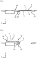
- FIGS. 4 and 5 represent a sectional view of the motorized sliding opening 2 along a sectional plane extending longitudinally and transversely, that is to say parallel to the L and T axes.
- the Figure 4 represents the motorized sliding opening 2 linked to a motor vehicle 36 when the motorized sliding opening 2 is in its closed position. In the closed position of the motorized sliding opening 2, the latter is held in said closed position by a locking system provided on the motorized sliding opening 2 and cooperating with a complementary device produced on the motor vehicle 36.
- the Figure 5 represents the motorized sliding opening 2 linked to said motor vehicle 36 when the motorized sliding opening 2 is in its open position.
- the power cable 4 is connected to the motorized sliding opening 2 at the second end 16 of the protective tray 10.
- the power cable 4 is able to follow said movement of the motorized sliding opening 2.
- the power cable 4 folds back on itself so that a part of the power cable 4 at the second end 16 of the protective tray 10 remains secured to the motorized sliding opening 2 while the rest of the power cable 4 is able to exit the housing 11 to allow the motorized sliding opening 2 to move.
- the present invention achieves the goal it set for itself by proposing an architecture of a motorized opening allowing a power cable to be protected while minimizing the size of the motorized sliding opening by means of a protective tray within which a housing allows a power cable to be housed by matching the shape of the power cable to minimize the space taken up by said housing.
Landscapes
- Engineering & Computer Science (AREA)
- Mechanical Engineering (AREA)
- Power-Operated Mechanisms For Wings (AREA)
Abstract
Description
- La présente invention concerne le domaine des ouvrants motorisés pour véhicule. La présente invention concerne plus particulièrement l'architecture de tels ouvrants permettant de connecter électriquement soit une source d'alimentation électrique à un moteur d'entraînement disposé dans l'ouvrant ou un dispositif de commande du verrouillage/déverrouillage à un moteur d'entraînement disposé sur la caisse du véhicule.
- Certains véhicules automobiles comprennent un ouvrant coulissant, un tel ouvrant pouvant être agencé sur un seul côté, de chaque côté ou à l'arrière d'une caisse du véhicule.
- Ces ouvrants sont configurés pour coulisser selon un premier sens de façon à générer une ouverture de l'ouvrant et selon un deuxième sens de façon à provoquer une fermeture de l'ouvrant. Le déplacement de l'ouvrant dans un sens ou dans l'autre peut être commandé de façon motorisée par l'utilisateur en activant à distance un ou plusieurs moteurs entraînant l'ouvrant selon ledit déplacement.
- Au moins le ou les moteurs impliqués dans le déplacement de l'ouvrant nécessitent d'être alimentés en électricité depuis un moyen de stockage en énergie électrique disposé dans le véhicule. À cet effet, le ou lesdits moteurs sont connectés au moyen de stockage en énergie électrique par un câble d'alimentation électrique.
- Ce câble d'alimentation doit pouvoir accompagner le déplacement de l'ouvrant par rapport au véhicule. Afin de le protéger, il est connu de disposer ledit câble d'alimentation directement dans un logement réalisé dans un panneau intérieur de l'ouvrant.
- En effet, ce logement est classiquement réalisé par emboutissage du panneau intérieur ce qui entraîne une consommation importante de place.
- La présente invention s'inscrit dans ce contexte et se propose de pallier au moins certains des inconvénients de l'art antérieur et notamment de proposer une architecture d'un ouvrant motorisé permettant de protéger un câble d'alimentation tout en minimisant l'encombrement de l'ouvrant pour protéger ledit câble d'alimentation.
- Ainsi, la présente invention porte sur un ouvrant coulissant motorisé destiné à équiper un véhicule, l'ouvrant coulissant motorisé comprenant un panneau extérieur, un panneau intérieur, au moins une partie d'un moyen d'entraînement configuré pour permettre l'ouverture et/ou la fermeture de l'ouvrant coulissant motorisé, ledit moyen d'entraînement comportant notamment une motorisation rendant l'ouvrant coulissant motorisé et au moins un câble d'alimentation disposé dans le volume de l'ouvrant coulissant motorisé, l'au moins un câble d'alimentation étant configuré pour permettre l'alimentation en énergie électrique d'au moins un moteur d'entraînement compris dans l'ouvrant coulissant motorisé et/ou d'une commande électrique du moyen d'entraînement comportant au moins un moteur d'entraînement disposé sur la caisse du véhicule sur laquelle l'ouvrant coulissant motorisé est destiné à être monté à coulissement, le panneau intérieur comprenant une découpe dans laquelle est logé un bac de protection, le bac de protection formant un logement de réception dans lequel est disposé l'au moins un câble d'alimentation, le bac de protection étant distinct du panneau intérieur et solidarisé audit panneau intérieur.
- L'ouvrant coulissant motorisé est une porte d'un véhicule, par exemple automobile, apte à se déplacer le long d'un rail de guidage, réalisé sur le véhicule ou sur l'ouvrant coulissant motorisé, pour permettre ou interdire l'accès au véhicule. L'ouvrant coulissant motorisé peut être une porte latérale ou encore une porte arrière d'un véhicule utilitaire dès lors que l'ouverture et/ou la fermeture de l'ouvrant coulissant motorisé est réalisée par un déplacement coulissant le long d'un moyen de guidage.
- Le moyen d'entraînement comprend au moins un moteur d'entraînement permettant de motoriser l'ouverture et/ou la fermeture de l'ouvrant coulissant motorisé. Le câble d'alimentation permet d'activer directement l'au moins un moteur d'entraînement ou une commande électrique dudit moteur d'entraînement pour permettre le déplacement de l'ouvrant coulissant motorisé.
- L'ouvrant coulissant motorisé est formé d'au moins un panneau extérieur et d'un panneau intérieur. Le panneau extérieur forme l'élément de carrosserie du véhicule directement au contact de l'environnement extérieur au véhicule.
- Ce panneau extérieur de carrosserie présente une structure permettant à l'ouvrant coulissant motorisé de résister aux chocs et agressions extérieures. Le panneau intérieur forme l'élément du véhicule pour l'habitacle du véhicule.
- Le volume de l'ouvrant coulissant motorisé est défini entre le panneau extérieur et le panneau intérieur. On comprend que le câble d'alimentation est disposé dans le volume de l'ouvrant coulissant motorisé de sorte que lorsque l'ouvrant coulissant motorisé est dans une position de fermeture, le câble d'alimentation est logé dans l'ouvrant coulissant motorisé entre le panneau extérieur et le panneau intérieur.
- La découpe du panneau intérieur est réalisée de sorte que cette dernière présente des dimensions complémentaires de celles du bac de protection pour loger le bac de protection dans ladite découpe en minimisant l'espace entre le bac de protection et le panneau intérieur. Ainsi la découpe du panneau intérieur est ajustée pour permettre à ce dernier de recevoir le bac de protection avec les parois définissant le bac de protection qui sont au plus près des bords du panneau intérieur délimitant la découpe.
- Le bac de protection est solidarisé au panneau intérieur et est destiné à loger un câble d'alimentation permettant de raccorder électriquement l'ouvrant coulissant motorisé. Ce câble d'alimentation est apte à accompagner l'ouvrant coulissant motorisé lors du déplacement de l'ouvrant coulissant motorisé entre une position d'ouverture et une position de fermeture. Le câble d'alimentation accompagne, lors du déplacement de l'ouvrant coulissant motorisé entre sa position d'ouverture et sa position de fermeture, le mouvement de l'ouvrant coulissant motorisé en restant au moins en partie logé dans le bac de protection. Au fur et à mesure du déplacement de l'ouvrant coulissant motorisé, le câble d'alimentation est apte à sortir du bac de protection pour accompagner le déplacement de l'ouvrant coulissant motorisé. On comprend qu'au moins une partie du câble d'alimentation est continuellement lié à un élément de l'ouvrant coulissant motorisé.
- Le bac de protection forme un logement, ledit logement étant disposé dans une épaisseur, ou volume, de l'ouvrant coulissant motorisé définie entre le panneau extérieur et le panneau intérieur. Le panneau extérieur et le panneau intérieur, avec au moins un des panneaux qui présente une forme non plane, sont solidarisés l'un à l'autre notamment sur leur périphérie pour générer un espace étanche à l'intérieur de l'ouvrant entre le panneau extérieur et le panneau intérieur. On comprend que l'épaisseur de l'ouvrant coulissant motorisé, au sein duquel est positionné le bac de protection, est formée de l'épaisseur du panneau extérieur, de l'épaisseur du panneau intérieur et de l'espace entre le panneau intérieur et le panneau extérieur.
- Selon une caractéristique de l'invention, le logement est disposé dans le volume de l'ouvrant coulissant motorisé défini entre le panneau extérieur et le panneau intérieur.
- Selon une caractéristique de l'invention, le logement est délimité au moins en partie par une paroi de fond et par une paroi latérale, la paroi latérale et la paroi de fond formant un premier angle l'une avec l'autre compris entre 90° et 120°. Un tel angle entre la paroi latérale, ou paroi latérale, et la paroi de fond permet de limiter l'encombrement du bac de protection au sein de l'ouvrant coulissant motorisé. En effet, en formant les parois du logement par un bac de protection rapporté dans une ouverture formée par la découpe du panneau intérieur, plutôt que directement par un emboutissage du panneau intérieur, on peut se rapprocher au maximum d'une réalisation à angle droit, ce qui limite l'angle entre la paroi de fond et la paroi latérale et ce qui permet de limiter l'espace pris par le bac de protection dans l'ouvrant coulissant motorisé.
- Selon une caractéristique de l'invention, le logement du bac de protection est délimité par un bord périphérique du bac de protection, le bord périphérique étant solidarisé au panneau intérieur. Le bord périphérique prolonge perpendiculairement la paroi latérale à une extrémité opposée à celle liée à la paroi de fond et il prolonge cette paroi latérale vers l'extérieur du bac de protection.
- Selon une caractéristique de l'invention, le logement présente une forme qui épouse la forme du câble d'alimentation. Pour limiter l'encombrement du bac de protection dans l'ouvrant coulissant motorisé, le logement présente des dimensions lui permettant d'épouser la forme du câble d'alimentation.
- Selon une caractéristique de l'invention, le câble d'alimentation est entièrement logé dans le logement formé par le bac de protection.
- Selon une caractéristique de l'invention, le bord périphérique est au contact du panneau intérieur par un appui plan.
- On comprend que le bord périphérique s'étend dans un plan parallèle au plan dans lequel s'inscrit la portion du panneau intérieur au contact du bord périphérique.
- Selon une caractéristique de l'invention, le bac de protection est solidarisé au panneau extérieur au niveau d'une portion du bac de protection distincte du bord périphérique.
- Selon une caractéristique de l'invention, la portion du bac de protection au niveau de laquelle est solidarisé le bac de protection au panneau extérieur est disposée en regard du logement. Cette portion du bac de protection permet d'augmenter la rigidité de l'ouvrant coulissant motorisé en générant un point de liaison entre le panneau extérieur et le panneau intérieur par l'intermédiaire du bac de protection. Plus spécifiquement, cette portion du bac de protection forme la paroi de fond du bac de protection.
- L'invention porte également sur un véhicule automobile comprenant un ouvrant coulissant motorisé conforme à au moins certaines des caractéristiques, le véhicule automobile comprenant un rail de guidage dans lequel l'ouvrant coulissant motorisé est apte à se déplacer entre une position d'ouverture et une position de fermeture, le bac de protection de l'ouvrant coulissant motorisé étant disposé directement en regard du rail de guidage. La disposition de l'ouvrant coulissant motorisé en regard du rail de guidage peut être réalisée en regard d'un bavolet., c'est-à-dire en regard d'un élément de protection du bas de caisse du véhicule. Une telle disposition du bac de protection au niveau du rail de guidage permet d'assurer une meilleure protection du câble d'alimentation, notamment en cas d'un choc provenant de l'extérieur du véhicule.
- D'autres caractéristiques, détails et avantages de l'invention ressortiront plus clairement à la lecture de la description qui suit d'une part, et d'exemples de réalisation donnés à titre indicatif et non limitatif en référence aux dessins schématique annexés d'autres part, sur lesquels :
- [
Fig.1 ] représente schématiquement une vue générale d'un ouvrant coulissant motorisé selon un mode de réalisation de l'invention destiné à équiper un véhicule automobile ; - [
Fig.2 ] représente schématiquement une vue générale d'un bac de protection de l'ouvrant coulissant motorisé visible sur lafigure 1 , le bac de protection étant destiné à loger un câble d'alimentation en énergie électrique pour un ou plusieurs moteurs électriques de l'ouvrant coulissant motorisé ; - [
Fig.3 ] représente schématiquement une vue de coupe locale de l'ouvrant coulissant motorisé visible sur lafigure 1 au niveau du bac de protection visible sur lafigure 2 ; - [
Fig.4 ] représente schématiquement une vue de coupe de l'ouvrant coulissant motorisé par un plan de coupe s'étendant longitudinalement et transversalement lorsque celui-ci est lié à un véhicule automobile et se trouve dans une position de fermeture ; - [
Fig.5 ] représente schématiquement une vue de coupe de l'ouvrant coulissant motorisé par un plan de coupe s'étendant longitudinalement et transversalement lorsque celui-ci est lié au véhicule automobile et se trouve dans une position d'ouverture. - Les caractéristiques, les variantes et les différentes formes de réalisation de l'invention peuvent être associées les unes avec les autres, selon diverses combinaisons, dans la mesure où elles ne sont pas incompatibles ou exclusives les unes des autres. On pourra notamment imaginer des variantes de l'invention ne comprenant qu'une sélection de caractéristiques décrites par la suite de manière isolée des autres caractéristiques décrites, si cette sélection de caractéristiques est suffisante pour conférer un avantage technique ou pour différencier l'invention par rapport à l'état de la technique.
- Sur les figures, les éléments communs à plusieurs figures conservent la même référence.
- Dans la description détaillée qui va suivre, les dénominations « longitudinale », « transversale » et « verticale » se réfèrent à l'orientation de l'ouvrant coulissant motorisé selon l'invention. Une direction longitudinale correspond à une direction d'avancement d'un véhicule équipé de l'ouvrant coulissant motorisé, cette direction longitudinale étant parallèle à un axe longitudinal L d'un repère L, V, T illustré sur les figures. Une direction transversale correspond à une direction perpendiculaire, dans un plan parallèle à la route sur laquelle le véhicule circule, à la direction d'avancement du véhicule équipé de l'ouvrant coulissant motorisé, cette direction transversale étant parallèle à un axe transversal T du repère L, V, T et cet axe transversal Tétant perpendiculaire à l'axe longitudinal L. Enfin, une direction verticale correspond à une direction parallèle à un axe vertical V du repère L, V, T, cet axe vertical V étant perpendiculaire à l'axe longitudinal L et à l'axe transversal T.
- La
figure 1 illustre un ouvrant coulissant motorisé 2 selon un mode de réalisation de l'invention. L'ouvrant coulissant motorisé 2 est destiné à équiper un véhicule, et plus particulièrement un véhicule automobile. Cet ouvrant coulissant motorisé 2 forme, dans le mode de réalisation représenté, une porte latérale d'un véhicule automobile. - L'ouvrant coulissant motorisé 2 est monté coulissant par rapport au véhicule de sorte à pouvoir se déplacer d'une part, dans un premier sens pour atteindre une position d'ouverture permettant, par exemple, à un utilisateur d'entrer ou de sortir du véhicule et d'autre part, dans un deuxième sens pour atteindre une position de fermeture empêchant, par exemple, un utilisateur d'entrée ou de sortir du véhicule. On comprend que le premier sens et le deuxième sens sont dans la même direction.
- Le déplacement de l'ouvrant coulissant motorisé 2 est permis, à titre d'exemple illustratif et non limitatif de l'invention, par des galets solidaires de l'ouvrant coulissant motorisé 2 circulant dans au moins un rail de guidage réalisé sur le véhicule automobile. On comprend que les galets sont liés à l'ouvrant coulissant motorisé 2 et coopèrent avec l'au moins un rail de guidage pour maintenir l'ouvrant coulissant motorisé 2 solidaire du véhicule automobile.
- Bien entendu, tout autre moyen permettant de faire coulisser l'ouvrant coulissant motorisé 2 entre une position d'ouverture et une position de fermeture tel que décrit précédemment peut être utilisé.
- Selon l'invention, le déplacement de l'ouvrant coulissant motorisé 2 est piloté par l'intermédiaire d'au moins un moteur d'entraînement configuré pour déplacer l'ouvrant coulissant motorisé 2 par rapport au véhicule entre la position d'ouverture et la position de fermeture. Le déplacement de l'ouvrant coulissant motorisé 2 par l'au moins un moteur d'entraînement peut être réalisé, à titre d'exemples illustratifs et non limitatifs de l'invention, en commandant le déplacement d'au moins un galet dans le rail de guidage ou encore par le déplacement d'une roue dentée solidaire soit de l'ouvrant coulissant motorisé 2, dans une crémaillère solidaire du véhicule automobile, soit de la caisse du véhicule, dans une crémaillère solidaire de l'ouvrant coulissant motorisé.
- L'au moins un moteur d'entraînement est un moteur électrique alimenté en énergie électrique depuis un moyen de stockage en énergie. Le moyen de stockage en énergie électrique est disposé dans le véhicule automobile et est relié à l'au moins un moteur d'entraînement par un câble d'alimentation 4, visible plus en détail sur les
figures 2 à 5 . Le moyen de stockage en énergie électrique peut par exemple être des batteries du véhicule automobile. - L'ouvrant coulissant motorisé 2 comprend un panneau extérieur 6 formant la partie de l'ouvrant coulissant motorisé 2 destinée à être au contact de l'environnement extérieur au véhicule automobile et un panneau intérieur 8 solidarisé au panneau extérieur 6 et formant la partie de l'ouvrant coulissant motorisé 2 destiné à être au contact de l'environnement interne à l'habitacle du véhicule automobile.
- En outre, l'ouvrant coulissant motorisé 2 comprend un bac de protection 10 dans lequel est disposé le câble d'alimentation 4. Le bac de protection 10 est solidarisé au panneau intérieur 8 et forme un logement 11 disposé dans un volume, ou une épaisseur, de l'ouvrant coulissant motorisé 2 délimité entre le panneau extérieur 6 et le panneau intérieur 8. Il convient de noter que le câble d'alimentation 4 est, tel qu'il sera décrit plus en détail dans la description qui suivra, apte à se déplacer dans le bac de protection 10 de sorte à accompagner l'ouvrant coulissant motorisé 2 lors de son déplacement entre sa position d'ouverture et sa position de fermeture. Pour loger le bac de protection 10, le panneau intérieur 8 comprend une découpe formant une ouverture aux dimensions du bac de protection 10. Cette découpe forme une portion vide au sein du panneau intérieur 8 permettant d'insérer le bac de protection 10 dans le volume de l'ouvrant coulissant motorisé 2.
- Il est remarquable sur le mode de réalisation représenté par la
figure 1 que l'ouvrant coulissant motorisé 2 comprend un bossage 12 disposé contre le panneau extérieur 6. Ce bossage 12 et le bac de protection 10 sont disposés l'un en regard de l'autre de sorte que le bossage 12 participe à protéger le bac de protection 10, par exemple d'un choc extérieur au véhicule et pouvant endommager le bac de protection 10. - La
figure 2 représente de façon très schématique le bac de protection 10 dans lequel est logé le câble d'alimentation 4. Plus spécifiquement, le bac de protection 10 s'étend selon une direction d'allongement principal longitudinale entre une première extrémité 14 et une deuxième extrémité 16. Le logement 11 s'étend au sein du bac de protection 10 entre la première extrémité 14 et la deuxième extrémité 16 parallèlement à la direction d'allongement principal longitudinale du bac de protection 10. - Le bac de protection 10 comprend un bord périphérique 18 qui s'étend sur tout le pourtour du bac de protection 10 en délimitant radialement l'ouverture du logement 11. Le bord périphérique 18 s'étendant, dans le mode de réalisation représenté, dans un plan parallèle à la direction longitudinale. Ce bord périphérique 18 est solidarisé avec le panneau intérieur 8 tel qu'il sera décrit plus en détail en lien avec la
figure 3 et permet d'assurer l'étanchéité entre le bac de protection 10 et le panneau intérieur 8. - En outre, le câble d'alimentation 4 est solidaire du bac de protection 10 au niveau de la deuxième extrémité 16 et mobile par rapport au bac de protection 10 au niveau de la première extrémité 14 tel qu'il sera décrit plus en détail en lien avec les
figures 4 et 5 . Le câble d'alimentation 4 est lié à un point de fixation 20 solidaire du véhicule. Au niveau de ce point de fixation 20 le câble d'alimentation 4 peut rejoindre le moyen de stockage en énergie électrique, le cas échéant en passant à travers la carrosserie du véhicule. - La
figure 3 représente une vue de coupe de l'ouvrant coulissant motorisé 2 par un plan de coupe s'étendant transversalement et verticalement, c'est-à-dire parallèlement aux axes T et V. - Le logement 11 du bac de protection 10 est délimité notamment par une paroi de fond 22 du bac de protection 10 qui s'étend à l'opposé de l'ouverture du logement 11 et en regard de la face interne du panneau extérieur 6, c'est-à-dire la face du panneau extérieur en regard du panneau intérieur 8, et par une paroi latérale 24 joignant la paroi de fond 22 au bord périphérique 18.
- La paroi de fond 22 s'étend dans un plan sensiblement parallèle à un plan dans lequel s'étend une portion du panneau extérieur 6 directement situé en regard de la paroi de fond 22. La paroi latérale 24 s'étend d'une extrémité transversale proximale du panneau extérieur 6 au contact de la paroi de fond 22 à une extrémité transversale distale du panneau extérieur 6 au contact du bord périphérique 18.
- En outre, la paroi latérale 24 forme un premier angle 26 avec la paroi de fond 22 compris entre 90° et 120°. De façon préférentielle ce premier angle 26 est inférieur à 100°. Un tel premier angle 26 permet de limiter l'encombrement du bac de protection 10 en permettant à la paroi latérale 24 d'épouser la forme du câble d'alimentation 4 pour limiter l'espace pris par le logement 11 sur l'ouvrant coulissant motorisé 2. Bien entendu, il doit être compris par « épouser » que la paroi latérale 24 est au plus proche du câble d'alimentation 4 sans limiter le déplacement dudit câble d'alimentation 4 dans le logement 11.
- La paroi latérale 24 forme un deuxième angle 28 avec le bord périphérique 18 qui, dans le mode de réalisation représenté, est égal au premier angle 26. En effet, dans le mode de réalisation représenté, le bord périphérique 18 s'étend dans un plan parallèle au plan dans lequel s'étend la paroi de fond 22. Plus spécifiquement, le deuxième angle 28 formé entre la paroi latérale 24 et le bord périphérique 18 est compris entre 90° et 120°. De façon préférentielle, ce deuxième angle 28 est inférieur à 100°.
- On comprend de la description du bac de protection 10 qui précède que le bac de protection 10 est une pièce rapportée du panneau intérieur 8, c'est-à-dire que le bac de protection 10 et le panneau intérieur 8 sont deux pièces formées séparément. Les valeurs d'angle précédemment évoquées sont obtenues du fait que le bac de protection 10 est distinct du panneau intérieur 8 ce qui permet de former lesdites valeurs d'angle.
- En outre, il est remarquable sur la
figure 3 que la paroi de fond 22 est solidarisée au panneau extérieur 6 par un organe de solidarisation 30 interposé entre la paroi de fond 22 et le panneau extérieur 6. Cet organe de solidarisation 30 participe à rigidifier l'ouvrant coulissant motorisé 2 au niveau du bac de protection 10. Plus précisément, dans le mode de réalisation représenté, l'organe de solidarisation 30 est formé par du mastic assurant un point de liaison directement avec le bac de protection 10 ce qui permet d'améliorer la rigidité de l'ouvrant coulissant motorisé 2 en créant un point de liaison entre le panneau extérieur 6 et le panneau intérieur 8 par l'intermédiaire de l'organe de solidarisation 30 et du bac de protection 10. - En effet le bac de protection 10 est, tel qu'il a pu être évoqué précédemment, solidarisé au panneau intérieur 8 au niveau du bord périphérique 18. Tel que visible sur la
figure 3 , le bord périphérique 18 s'étend dans un plan parallèle au plan de la portion du panneau intérieur 8 situé aux abords du bord périphérique 18. Une telle caractéristique permet de réaliser une solidarisation, notamment par clipsage, entre le panneau intérieur 8 et le bord périphérique 18 formant un appui plan. Un tel appui plan permet notamment, à titre d'exemple illustratif et non limitatif de l'invention, de positionner un panneau de garnissage contre le panneau intérieur 8 et le bord périphérique. - La
figure 3 permet également de mettre en évidence une coupe du câble d'alimentation 4. Le câble d'alimentation 4 est formé d'une chaîne porte-câble et comprend une succession de maillons articulés 32 et au moins un câble électrique 34. Cette configuration du câble d'alimentation 4 lui permet d'accompagner le mouvement de l'ouvrant coulissant motorisé 2. - Les
figures 4 et 5 représentent une vue de coupe de l'ouvrant coulissant motorisé 2 selon un plan de coupe s'étendant longitudinalement et transversalement, c'est-à-dire parallèlement aux axes L et T. - Plus spécifiquement, la
figure 4 représente l'ouvrant coulissant motorisé 2 lié à un véhicule automobile 36 lorsque l'ouvrant coulissant motorisé 2 est dans sa position de fermeture. Dans la position de fermeture de l'ouvrant coulissant motorisé 2, ce dernier est maintenu dans ladite position de fermeture par un système de verrouillage prévu sur l'ouvrant coulissant motorisé 2 et coopérant avec un dispositif complémentaire réalisé sur le véhicule automobile 36. Lafigure 5 représente quant à elle l'ouvrant coulissant motorisé 2 lié audit véhicule automobile 36 lorsque l'ouvrant coulissant motorisé 2 est dans sa position d'ouverture. - Tel que visible par un regard croisé entre les
figures 4 et 5 , le câble d'alimentation 4 est lié à l'ouvrant coulissant motorisé 2 au niveau de la deuxième extrémité 16 du bac de protection 10. Lors du déplacement de l'ouvrant coulissant motorisé 2 le câble d'alimentation 4 est apte à suivre ledit déplacement de l'ouvrant coulissant motorisé 2. En effet, tel qu'il est remarquable sur lesfigures 4 et 5 lors du passage de l'ouvrant coulissant motorisé 2 de sa position de fermeture à sa position d'ouverture, le câble d'alimentation 4 se replie sur lui-même de telle sorte qu'une partie du câble d'alimentation 4 au niveau de la deuxième extrémité 16 du bac de protection 10 reste solidaire de l'ouvrant coulissant motorisé 2 tandis que le reste du câble d'alimentation 4 est apte à sortir du logement 11 pour permettre le déplacement de l'ouvrant coulissant motorisé 2. - Bien entendu, on comprend que lors du passage de l'ouvrant coulissant motorisé 2 de sa position d'ouverture à sa position de fermeture, le câble d'alimentation 4 vient se loger dans le logement 11.
- Ainsi la présente invention atteint bien le but qu'elle s'était fixé en proposant une architecture d'un ouvrant motorisé permettant de protéger un câble d'alimentation tout en minimisant l'encombrement de l'ouvrant coulissant motorisé au moyen d'un bac de protection au sein duquel un logement permet de loger un câble d'alimentation en épousant les formes du câble d'alimentation pour minimiser l'espace dudit logement.
- La présente invention ne saurait toutefois se limiter aux moyens et configurations décrits et illustrés ici et elle s'étend également à tout moyen et toute configuration équivalents ainsi qu'à toute combinaison techniquement opérante de tels moyens.
Claims (11)
- Ouvrant coulissant motorisé (2) destiné à équiper un véhicule (36), l'ouvrant coulissant motorisé (2) comprenant un panneau extérieur (6), un panneau intérieur (8), au moins une partie d'un moyen d'entraînement configuré pour permettre l'ouverture et/ou la fermeture de l'ouvrant coulissant motorisé (2), ledit moyen d'entraînement comportant notamment une motorisation rendant l'ouvrant coulissant motorisé (2) et au moins un câble d'alimentation (4) disposé dans le volume de l'ouvrant coulissant motorisé (2), l'au moins un câble d'alimentation (4) étant configuré pour permettre l'alimentation en énergie électrique d'au moins un moteur d'entraînement compris dans l'ouvrant coulissant motorisé (2) et/ou d'une commande électrique du moyen d'entraînement comportant au moins un moteur d'entraînement disposé sur la caisse du véhicule sur laquelle l'ouvrant coulissant motorisé (2) est destiné à être monté à coulissement, le panneau intérieur (8) comprenant une découpe dans laquelle est logé un bac de protection (10), le bac de protection (10) forme un logement (11) de réception dans lequel est disposé l'au moins un câble d'alimentation (4), le bac de protection (10) étant distinct du panneau intérieur (8) et solidarisé audit panneau intérieur (8).
- Ouvrant coulissant motorisé (2) selon la revendication précédente, dans lequel le logement (11) est disposé dans le volume de l'ouvrant coulissant motorisé (2) défini entre le panneau extérieur (6) et le panneau intérieur (8).
- Ouvrant coulissant motorisé (2) selon la revendication précédente, dans lequel le logement (11) est délimité au moins en partie par une paroi de fond (22) et par une paroi latérale (24), la paroi latérale (24) et la paroi de fond (22) formant un premier angle (26) l'une avec l'autre compris entre 90° et 120°.
- Ouvrant coulissant motorisé (2) selon l'une quelconque des revendications 2 ou 3, dans lequel le logement (11) du bac de protection (10) est délimité par un bord périphérique (18) du bac de protection (10), le bord périphérique (18) étant solidarisé au panneau intérieur (8).
- Ouvrant coulissant motorisé (2) selon l'une quelconque des revendications précédentes, dans lequel le logement (11) présente une forme qui épouse la forme du câble d'alimentation (4).
- Ouvrant coulissant motorisé (2) selon l'une quelconque des revendications précédentes, dans lequel le câble d'alimentation (4) est entièrement logé dans le logement (11) formé par le bac de protection (10).
- Ouvrant coulissant motorisé (2) selon la revendication 4, dans lequel le bord périphérique (18) est au contact du panneau intérieur (8) par un appui plan.
- Ouvrant coulissant motorisé (2) selon la revendication 7, dans lequel le logement (11) est délimité par le bord périphérique (18).
- Ouvrant coulissant motorisé (2) selon l'une quelconque des revendications 4 et 8, dans lequel le bac de protection (10) est solidarisé au panneau extérieur (6) au niveau d'une portion du bac de protection (10) distincte du bord périphérique (18).
- Ouvrant coulissant motorisé (2) selon la revendication précédente, dans lequel la portion du bac de protection (10) au niveau de laquelle est solidarisé le bac de protection (10) au panneau extérieur (6) est disposée en regard du logement (11).
- Véhicule automobile (36) comprenant un ouvrant coulissant motorisé (2) selon l'une quelconque des revendications précédentes, le véhicule automobile (36) comprenant un rail de guidage dans lequel l'ouvrant coulissant motorisé (2) est apte à se déplacer entre une position d'ouverture et une position de fermeture, le bac de protection (10) de l'ouvrant coulissant motorisé (2) étant disposé directement en regard du rail de guidage.
Applications Claiming Priority (1)
| Application Number | Priority Date | Filing Date | Title |
|---|---|---|---|
| FR2309606A FR3152823B1 (fr) | 2023-09-12 | 2023-09-12 | Ouvrant coulissant motorisé d’un véhicule. |
Publications (1)
| Publication Number | Publication Date |
|---|---|
| EP4527650A1 true EP4527650A1 (fr) | 2025-03-26 |
Family
ID=88839154
Family Applications (1)
| Application Number | Title | Priority Date | Filing Date |
|---|---|---|---|
| EP24199872.3A Pending EP4527650A1 (fr) | 2023-09-12 | 2024-09-11 | Ouvrant coulissant motorisé d'un véhicule |
Country Status (2)
| Country | Link |
|---|---|
| EP (1) | EP4527650A1 (fr) |
| FR (1) | FR3152823B1 (fr) |
Citations (4)
| Publication number | Priority date | Publication date | Assignee | Title |
|---|---|---|---|---|
| JP2004034759A (ja) * | 2002-07-01 | 2004-02-05 | Sumitomo Wiring Syst Ltd | 車両用スライドドアの給電装置 |
| JP3861163B2 (ja) * | 2001-07-12 | 2006-12-20 | 日産自動車株式会社 | スライドドア給電構造 |
| EP2052896A1 (fr) * | 2007-10-25 | 2009-04-29 | Mitsubishi Jidosha Kogyo Kabushiki Kaisha | Système d'ouverture et de fermeture de porte coulissante et battante |
| US7669368B2 (en) * | 2004-12-06 | 2010-03-02 | Brose Fahrzeugteile Gmbh & Co. Kg | Sliding door for motor vehicles and method for the assembly thereof |
-
2023
- 2023-09-12 FR FR2309606A patent/FR3152823B1/fr active Active
-
2024
- 2024-09-11 EP EP24199872.3A patent/EP4527650A1/fr active Pending
Patent Citations (4)
| Publication number | Priority date | Publication date | Assignee | Title |
|---|---|---|---|---|
| JP3861163B2 (ja) * | 2001-07-12 | 2006-12-20 | 日産自動車株式会社 | スライドドア給電構造 |
| JP2004034759A (ja) * | 2002-07-01 | 2004-02-05 | Sumitomo Wiring Syst Ltd | 車両用スライドドアの給電装置 |
| US7669368B2 (en) * | 2004-12-06 | 2010-03-02 | Brose Fahrzeugteile Gmbh & Co. Kg | Sliding door for motor vehicles and method for the assembly thereof |
| EP2052896A1 (fr) * | 2007-10-25 | 2009-04-29 | Mitsubishi Jidosha Kogyo Kabushiki Kaisha | Système d'ouverture et de fermeture de porte coulissante et battante |
Also Published As
| Publication number | Publication date |
|---|---|
| FR3152823A1 (fr) | 2025-03-14 |
| FR3152823B1 (fr) | 2025-08-15 |
Similar Documents
| Publication | Publication Date | Title |
|---|---|---|
| EP2151343B1 (fr) | Véhicule de petite taille | |
| FR2798327A1 (fr) | Systeme de toit decouvrable et vehicule equipe de ce systeme | |
| FR2955077A1 (fr) | Vehicule dote d'un plancher apte a recevoir une batterie et une poutre de renforcement | |
| EP2726309B1 (fr) | Dispositif de protection laterale pour vehicule automobile et vehicule automobile associe | |
| FR2959462A1 (fr) | Dispositif de rangement d'une rallonge d'alimentation electrique d'un vehicule | |
| EP2920026B1 (fr) | Siège de véhicule automobile comportant un dispositif de support pour un connecteur électrique et véhicule automobile associé | |
| FR2821035A1 (fr) | Agencement de coffre d'un vehicule automobile | |
| FR3035627A1 (fr) | Dispositif d’arret de charge pivotant a l’interieur de l’habitacle d’un vehicule | |
| FR3152823A1 (fr) | Ouvrant coulissant motorisé d’un véhicule. | |
| FR2917031A1 (fr) | Vehicule automobile comprenant un module de rangement pivotant | |
| WO2021219300A1 (fr) | Véhicule doté d'une traverse centrale arrière multifonction | |
| FR2921315A1 (fr) | Systeme de rangement d'un boitier electronique rotatif dans une partie d'habitacle de vehicule automobile. | |
| EP4622824A1 (fr) | Ouvrant comportant une trappe d'accès à une prise électrique fixée sur une caisse de véhicule | |
| FR2966779A1 (fr) | Dispositif de protection laterale pour un vehicule | |
| WO2010081964A1 (fr) | Vehicule equipe d'une malle mobile | |
| EP3670271B1 (fr) | Dispositif de déploiement d'une caméra pour véhicule motorisé | |
| FR2921305A3 (fr) | Vehicule automobile comportant un ouvrant muni d'une trappe | |
| FR2698057A1 (fr) | Accoudoir de siège de véhicule automobile contenant un appareil téléphonique. | |
| FR3152250A1 (fr) | Vehicule automobile electrique ou hybride comportant deux battants aptes a proteger un connecteur electrique de rechargement | |
| EP4674661A1 (fr) | Trappe de chargement comportant un moyen d' étanchéité amélioré pour véhicule | |
| FR3059609B1 (fr) | Dispositif d'articulation d'une porte laterale de vehicule | |
| FR3143443A1 (fr) | Enjoliveur de hayon de véhicule automobile | |
| FR3139516A1 (fr) | Véhicule automobile avec une trappe de recharge électrique sur le montant arrière | |
| FR3160142A1 (fr) | Arrangement de coffre pour véhicule automobile comportant une benne extérieure | |
| FR3164173A1 (fr) | Plancher pour un véhicule automobile |
Legal Events
| Date | Code | Title | Description |
|---|---|---|---|
| PUAI | Public reference made under article 153(3) epc to a published international application that has entered the european phase |
Free format text: ORIGINAL CODE: 0009012 |
|
| STAA | Information on the status of an ep patent application or granted ep patent |
Free format text: STATUS: THE APPLICATION HAS BEEN PUBLISHED |
|
| AK | Designated contracting states |
Kind code of ref document: A1 Designated state(s): AL AT BE BG CH CY CZ DE DK EE ES FI FR GB GR HR HU IE IS IT LI LT LU LV MC ME MK MT NL NO PL PT RO RS SE SI SK SM TR |
|
| STAA | Information on the status of an ep patent application or granted ep patent |
Free format text: STATUS: REQUEST FOR EXAMINATION WAS MADE |
|
| 17P | Request for examination filed |
Effective date: 20250925 |
|
| GRAP | Despatch of communication of intention to grant a patent |
Free format text: ORIGINAL CODE: EPIDOSNIGR1 |
|
| STAA | Information on the status of an ep patent application or granted ep patent |
Free format text: STATUS: GRANT OF PATENT IS INTENDED |
|
| RIC1 | Information provided on ipc code assigned before grant |
Ipc: B60J 5/06 20060101AFI20251121BHEP |
|
| INTG | Intention to grant announced |
Effective date: 20251222 |
|
| GRAS | Grant fee paid |
Free format text: ORIGINAL CODE: EPIDOSNIGR3 |
|
| GRAA | (expected) grant |
Free format text: ORIGINAL CODE: 0009210 |
|
| STAA | Information on the status of an ep patent application or granted ep patent |
Free format text: STATUS: THE PATENT HAS BEEN GRANTED |