EP4527319A2 - Vorrichtung zur abgabe von biomaterial sowie entsprechende systeme und verfahren - Google Patents
Vorrichtung zur abgabe von biomaterial sowie entsprechende systeme und verfahren Download PDFInfo
- Publication number
- EP4527319A2 EP4527319A2 EP25156099.1A EP25156099A EP4527319A2 EP 4527319 A2 EP4527319 A2 EP 4527319A2 EP 25156099 A EP25156099 A EP 25156099A EP 4527319 A2 EP4527319 A2 EP 4527319A2
- Authority
- EP
- European Patent Office
- Prior art keywords
- biomaterial
- slot
- floor surface
- along
- carrier
- Prior art date
- Legal status (The legal status is an assumption and is not a legal conclusion. Google has not performed a legal analysis and makes no representation as to the accuracy of the status listed.)
- Pending
Links
Images













Classifications
-
- A—HUMAN NECESSITIES
- A61—MEDICAL OR VETERINARY SCIENCE; HYGIENE
- A61B—DIAGNOSIS; SURGERY; IDENTIFICATION
- A61B17/00—Surgical instruments, devices or methods
- A61B17/56—Surgical instruments or methods for treatment of bones or joints; Devices specially adapted therefor
- A61B17/58—Surgical instruments or methods for treatment of bones or joints; Devices specially adapted therefor for osteosynthesis, e.g. bone plates, screws or setting implements
- A61B17/68—Internal fixation devices, including fasteners and spinal fixators, even if a part thereof projects from the skin
- A61B17/70—Spinal positioners or stabilisers, e.g. stabilisers comprising fluid filler in an implant
- A61B17/7061—Spinal positioners or stabilisers, e.g. stabilisers comprising fluid filler in an implant for stabilising vertebrae or discs by improving the condition of their tissues, e.g. using implanted medication or fluid exchange
-
- A—HUMAN NECESSITIES
- A61—MEDICAL OR VETERINARY SCIENCE; HYGIENE
- A61B—DIAGNOSIS; SURGERY; IDENTIFICATION
- A61B17/00—Surgical instruments, devices or methods
- A61B17/56—Surgical instruments or methods for treatment of bones or joints; Devices specially adapted therefor
- A61B17/58—Surgical instruments or methods for treatment of bones or joints; Devices specially adapted therefor for osteosynthesis, e.g. bone plates, screws or setting implements
- A61B17/68—Internal fixation devices, including fasteners and spinal fixators, even if a part thereof projects from the skin
- A61B17/70—Spinal positioners or stabilisers, e.g. stabilisers comprising fluid filler in an implant
- A61B17/7097—Stabilisers comprising fluid filler in an implant, e.g. balloon; devices for inserting or filling such implants
-
- A—HUMAN NECESSITIES
- A61—MEDICAL OR VETERINARY SCIENCE; HYGIENE
- A61B—DIAGNOSIS; SURGERY; IDENTIFICATION
- A61B17/00—Surgical instruments, devices or methods
- A61B17/56—Surgical instruments or methods for treatment of bones or joints; Devices specially adapted therefor
- A61B17/58—Surgical instruments or methods for treatment of bones or joints; Devices specially adapted therefor for osteosynthesis, e.g. bone plates, screws or setting implements
- A61B17/88—Osteosynthesis instruments; Methods or means for implanting or extracting internal or external fixation devices
- A61B17/8802—Equipment for handling bone cement or other fluid fillers
- A61B17/8805—Equipment for handling bone cement or other fluid fillers for introducing fluid filler into bone or extracting it
- A61B17/8811—Equipment for handling bone cement or other fluid fillers for introducing fluid filler into bone or extracting it characterised by the introducer tip, i.e. the part inserted into or onto the bone
-
- A—HUMAN NECESSITIES
- A61—MEDICAL OR VETERINARY SCIENCE; HYGIENE
- A61B—DIAGNOSIS; SURGERY; IDENTIFICATION
- A61B17/00—Surgical instruments, devices or methods
- A61B17/56—Surgical instruments or methods for treatment of bones or joints; Devices specially adapted therefor
- A61B17/58—Surgical instruments or methods for treatment of bones or joints; Devices specially adapted therefor for osteosynthesis, e.g. bone plates, screws or setting implements
- A61B17/88—Osteosynthesis instruments; Methods or means for implanting or extracting internal or external fixation devices
- A61B17/8802—Equipment for handling bone cement or other fluid fillers
- A61B17/8805—Equipment for handling bone cement or other fluid fillers for introducing fluid filler into bone or extracting it
- A61B17/8819—Equipment for handling bone cement or other fluid fillers for introducing fluid filler into bone or extracting it characterised by the introducer proximal part, e.g. cannula handle, or by parts which are inserted inside each other, e.g. stylet and cannula
-
- A—HUMAN NECESSITIES
- A61—MEDICAL OR VETERINARY SCIENCE; HYGIENE
- A61B—DIAGNOSIS; SURGERY; IDENTIFICATION
- A61B17/00—Surgical instruments, devices or methods
- A61B17/56—Surgical instruments or methods for treatment of bones or joints; Devices specially adapted therefor
- A61B17/58—Surgical instruments or methods for treatment of bones or joints; Devices specially adapted therefor for osteosynthesis, e.g. bone plates, screws or setting implements
- A61B17/88—Osteosynthesis instruments; Methods or means for implanting or extracting internal or external fixation devices
- A61B17/8802—Equipment for handling bone cement or other fluid fillers
- A61B17/8805—Equipment for handling bone cement or other fluid fillers for introducing fluid filler into bone or extracting it
- A61B17/8822—Equipment for handling bone cement or other fluid fillers for introducing fluid filler into bone or extracting it characterised by means facilitating expulsion of fluid from the introducer, e.g. a screw pump plunger, hydraulic force transmissions, application of vibrations or a vacuum
-
- A—HUMAN NECESSITIES
- A61—MEDICAL OR VETERINARY SCIENCE; HYGIENE
- A61B—DIAGNOSIS; SURGERY; IDENTIFICATION
- A61B17/00—Surgical instruments, devices or methods
- A61B17/56—Surgical instruments or methods for treatment of bones or joints; Devices specially adapted therefor
- A61B17/58—Surgical instruments or methods for treatment of bones or joints; Devices specially adapted therefor for osteosynthesis, e.g. bone plates, screws or setting implements
- A61B17/88—Osteosynthesis instruments; Methods or means for implanting or extracting internal or external fixation devices
- A61B17/8802—Equipment for handling bone cement or other fluid fillers
- A61B17/8833—Osteosynthesis tools specially adapted for handling bone cement or fluid fillers; Means for supplying bone cement or fluid fillers to introducing tools, e.g. cartridge handling means
-
- A—HUMAN NECESSITIES
- A61—MEDICAL OR VETERINARY SCIENCE; HYGIENE
- A61F—FILTERS IMPLANTABLE INTO BLOOD VESSELS; PROSTHESES; DEVICES PROVIDING PATENCY TO, OR PREVENTING COLLAPSING OF, TUBULAR STRUCTURES OF THE BODY, e.g. STENTS; ORTHOPAEDIC, NURSING OR CONTRACEPTIVE DEVICES; FOMENTATION; TREATMENT OR PROTECTION OF EYES OR EARS; BANDAGES, DRESSINGS OR ABSORBENT PADS; FIRST-AID KITS
- A61F2/00—Filters implantable into blood vessels; Prostheses, i.e. artificial substitutes or replacements for parts of the body; Appliances for connecting them with the body; Devices providing patency to, or preventing collapsing of, tubular structures of the body, e.g. stents
- A61F2/02—Prostheses implantable into the body
- A61F2/30—Joints
- A61F2/46—Special tools for implanting artificial joints
- A61F2/4601—Special tools for implanting artificial joints for introducing bone substitute, for implanting bone graft implants or for compacting them in the bone cavity
-
- A—HUMAN NECESSITIES
- A61—MEDICAL OR VETERINARY SCIENCE; HYGIENE
- A61F—FILTERS IMPLANTABLE INTO BLOOD VESSELS; PROSTHESES; DEVICES PROVIDING PATENCY TO, OR PREVENTING COLLAPSING OF, TUBULAR STRUCTURES OF THE BODY, e.g. STENTS; ORTHOPAEDIC, NURSING OR CONTRACEPTIVE DEVICES; FOMENTATION; TREATMENT OR PROTECTION OF EYES OR EARS; BANDAGES, DRESSINGS OR ABSORBENT PADS; FIRST-AID KITS
- A61F2/00—Filters implantable into blood vessels; Prostheses, i.e. artificial substitutes or replacements for parts of the body; Appliances for connecting them with the body; Devices providing patency to, or preventing collapsing of, tubular structures of the body, e.g. stents
- A61F2/02—Prostheses implantable into the body
- A61F2/30—Joints
- A61F2/46—Special tools for implanting artificial joints
- A61F2/4603—Special tools for implanting artificial joints for insertion or extraction of endoprosthetic joints or of accessories thereof
- A61F2/4611—Special tools for implanting artificial joints for insertion or extraction of endoprosthetic joints or of accessories thereof of spinal prostheses
-
- A—HUMAN NECESSITIES
- A61—MEDICAL OR VETERINARY SCIENCE; HYGIENE
- A61F—FILTERS IMPLANTABLE INTO BLOOD VESSELS; PROSTHESES; DEVICES PROVIDING PATENCY TO, OR PREVENTING COLLAPSING OF, TUBULAR STRUCTURES OF THE BODY, e.g. STENTS; ORTHOPAEDIC, NURSING OR CONTRACEPTIVE DEVICES; FOMENTATION; TREATMENT OR PROTECTION OF EYES OR EARS; BANDAGES, DRESSINGS OR ABSORBENT PADS; FIRST-AID KITS
- A61F2/00—Filters implantable into blood vessels; Prostheses, i.e. artificial substitutes or replacements for parts of the body; Appliances for connecting them with the body; Devices providing patency to, or preventing collapsing of, tubular structures of the body, e.g. stents
- A61F2/02—Prostheses implantable into the body
- A61F2/30—Joints
- A61F2/46—Special tools for implanting artificial joints
- A61F2/4657—Measuring instruments used for implanting artificial joints
-
- A—HUMAN NECESSITIES
- A61—MEDICAL OR VETERINARY SCIENCE; HYGIENE
- A61B—DIAGNOSIS; SURGERY; IDENTIFICATION
- A61B17/00—Surgical instruments, devices or methods
- A61B17/02—Surgical instruments, devices or methods for holding wounds open, e.g. retractors; Tractors
- A61B17/025—Joint distractors
- A61B2017/0256—Joint distractors for the spine
-
- A—HUMAN NECESSITIES
- A61—MEDICAL OR VETERINARY SCIENCE; HYGIENE
- A61B—DIAGNOSIS; SURGERY; IDENTIFICATION
- A61B17/00—Surgical instruments, devices or methods
- A61B17/56—Surgical instruments or methods for treatment of bones or joints; Devices specially adapted therefor
- A61B2017/564—Methods for bone or joint treatment
-
- A—HUMAN NECESSITIES
- A61—MEDICAL OR VETERINARY SCIENCE; HYGIENE
- A61F—FILTERS IMPLANTABLE INTO BLOOD VESSELS; PROSTHESES; DEVICES PROVIDING PATENCY TO, OR PREVENTING COLLAPSING OF, TUBULAR STRUCTURES OF THE BODY, e.g. STENTS; ORTHOPAEDIC, NURSING OR CONTRACEPTIVE DEVICES; FOMENTATION; TREATMENT OR PROTECTION OF EYES OR EARS; BANDAGES, DRESSINGS OR ABSORBENT PADS; FIRST-AID KITS
- A61F2/00—Filters implantable into blood vessels; Prostheses, i.e. artificial substitutes or replacements for parts of the body; Appliances for connecting them with the body; Devices providing patency to, or preventing collapsing of, tubular structures of the body, e.g. stents
- A61F2/02—Prostheses implantable into the body
- A61F2/28—Bones
- A61F2002/2835—Bone graft implants for filling a bony defect or an endoprosthesis cavity, e.g. by synthetic material or biological material
Definitions
- Bone growth inducing material such as bone graft and/or bone graft substitutes, is commonly used in connection with fusion cages to encourage bone growth around and/or through the fusion cage or spacer to enhance the speed and strength at which the adjacent vertebrae fuse together.
- the disc space evacuated by resected disc material e.g., nucleus pulposus and/or anulus fibrosis
- the cage or spacer can be packed with bone growth inducing material prior to insertion.
- a system for delivering flowable biomaterial into an intervertebral disc space between an upper vertebral body and a lower vertebral body of a patient includes a plurality of delivery bodies each configured for delivering the biomaterial and each defining: a proximal end, a distal end spaced from the proximal end along a longitudinal direction, a cannulation extending from the proximal end to at least one opening adjacent the distal end, and a distal region including a tip that extends to the distal end.
- the distal region defines a maximum height at a location proximally spaced from the distal end. The maximum height is measured along a second direction perpendicular to the longitudinal direction.
- a system for loading flowable biomaterial into an instrument for subsequent delivery into an intervertebral disc space includes a loading tray having a tray body that has a floor surface configured to receive the biomaterial.
- the tray body also includes a plurality of sidewalls at a periphery of the floor surface.
- the plurality of sidewalls and the floor surface cooperatively define a tray volume.
- At least one of the plurality of sidewalls defines at least one access opening extending therethrough.
- the tray body also includes at least one slot that is elongate along a longitudinal direction, recessed from the floor surface, open to the tray volume, and in communication with the at least one access opening.
- the system also includes an instrument having a portion that is elongate and is configured for insertion within the at least one elongate slot along the longitudinal direction.
- the instrument defines a channel, where the channel is configured such that, when the instrument resides in the at least one slot, the channel is elongate along the longitudinal direction and is orientable so as to be open to the tray volume.
- an assembly for loading flowable biomaterial into an instrument for subsequent delivery to a target location within a patient includes a loading device that has a housing which has a base surface.
- the loading device includes a body portion that defines at least one elongate slot that is configured to receive an elongate portion of an instrument having an open, elongate channel.
- the loading device also includes a rotary member coupled to the housing such that a volume of space is at least partially defined between the rotary member and the base surface, where the volume of space is configured to contain the biomaterial.
- the rotary member includes at least one member configured to move a quantity of the biomaterial from the volume of space into the at least one elongate slot responsive to relative rotation between the rotary member and the housing.
- an assembly for loading flowable biomaterial into an instrument for subsequent delivery to a target location within a includes a loading device that has a housing which has an inner surface within an interior of the housing.
- a plurality of elongate slots are defined within the inner surface and are each configured to receive an elongate portion of an instrument having an open, elongate channel.
- the loading device includes a rotary member coupled to the housing such that a volume of space is defined between the rotary member and the housing, wherein the volume of space is configured to contain the biomaterial and is in communication with the at least one slot.
- the rotary member includes at least one member configured to move a quantity of the biomaterial from the volume of space into the plurality of elongate slots responsive to relative rotation between the rotary member and the housing.
- inventions also pertain to delivery instruments with distal geometries that allow the delivery instruments to double as trial instruments, such as for ascertaining the disc height between adjacent vertebral bodies, for example.
- Such trial-capable distal geometries can be particularly beneficial in that they can effectively eliminate a subsequent trialing procedure for an implant, such as an intervertebral fusion cage, such as an expandable fusion cage, to be inserted within the intervertebral disc space.
- inventions also pertain to delivery instruments having retention mechanisms that iterates between an open position, in which a loading instrument carrying a quantity of biomaterial is insertable within the instrument, and a closed position, in which the biomaterial is retained within the delivery instrument while the loading instrument is retracted therefrom.
- biomaterial-loading systems including biomaterial-loading devices and assemblies, for depositing biomaterial in one or more loading instruments for subsequent insertion within one or more delivery instruments.
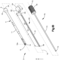
- FIG. 1A an exemplary embodiment of an instrument assembly 2 is shown for dispensing of otherwise delivering flowable biomaterial 9 to an intervertebral disc space (hereinafter referred to as the "disc space") between a superior vertebral body and an inferior vertebral body.
- the flowable biomaterial 9 is also referred to herein simply as “the material” 9, and can include any of the flowable biomaterials described above.
- the instrument assembly 2 can be referred to as a "system”, and includes instrumentation, such as an outer delivery body 4, a carrier 50 that is insertable within the delivery body 4 for loading biomaterial 9 in the delivery body 4, and an advancement member 70 insertable within the carrier 50 and delivery body 4 for advancing the biomaterial 9 through the delivery body 4 to the disc space.
- instrumentation such as an outer delivery body 4, a carrier 50 that is insertable within the delivery body 4 for loading biomaterial 9 in the delivery body 4, and an advancement member 70 insertable within the carrier 50 and delivery body 4 for advancing the biomaterial 9 through the delivery body 4 to the disc space.
- instrumentation such as an outer delivery body 4, a carrier 50 that is insertable within the delivery body 4 for loading biomaterial 9 in the delivery body 4, and an advancement member 70 insertable within the carrier 50 and delivery body 4 for advancing the biomaterial 9 through the delivery body 4 to the disc space.
- an advancement member 70 insertable within the carrier 50 and delivery body 4 for advancing the biomaterial 9 through the delivery body 4 to the disc space.
- the outer delivery body 4 has a proximal end 6 and a distal end 8 spaced from the proximal end 6 along a longitudinal direction X that is oriented along a central axis 10 of the delivery body 4. It should be appreciated that the central axis 10 of the delivery body 4 can effectively define the central axis of the instrument assembly 2.
- the delivery body 4 defines an outer surface 11 and a cannulation 12 opposite the outer surface 11 with respect to a radial direction R perpendicular to the central axis 10 (and thus also perpendicular to the longitudinal direction X). Accordingly, the delivery body 4 can also be referred to as a "cannulated" body.
- the delivery body 4 can define a mounting formation 18 at the proximal end 6.
- the mounting formation 18 can be configured to receive a handle component, such as a handle connection 20 attached to a handle 22, as shown.
- the mounting formation 18 can also define a proximal surface 24 that defines the proximal end 6 of the delivery body 4.
- the elongate channel opening 53 is defined by surfaces of the elongate body portion 55 that extend inwardly from the outer surface 51 of the elongate body portion 55 to the channel 52, such as along the radial direction R, as shown in Fig. 1D .
- the elongate channel opening 53 allows the channel 52 to be open to an exterior of the elongate body portion 55 along the direction offset from the longitudinal direction X. In this manner, the channel 52 is also open to the cannulation 12 along such a direction when the elongate body portion 55 is inserted within the delivery body 4.
- the elongate channel opening 53 (and thus the channel 52) defines a length X1 measured along the longitudinal direction X.
- the carrier 50 can include a stop member 60 that defines the proximal end 54 of the carrier 50.
- the stop member 60 can define a proximal surface 62 and a distal surface 64 spaced from each other along the longitudinal direction X.
- the proximal surface 62 can define the proximal end 54 of the carrier 50.
- the carrier 50 is configured to advance within the cannulation 12 of the delivery body 4 until the distal surface 64 of the stop member 60 abuts the proximal surface 24 of the mounting formation 18 of the delivery body 4, which defines a fully inserted position of the carrier 50 relative to the delivery body 4.
- the channel 52 of the carrier 50 has a generally trough-like shape in a reference plane orthogonal to the central axis 10.
- the elongate channel opening 53 defines an opening angle A1 that can be in a range of about 30 degrees to about 180 degrees about the central axis 10. In some embodiments, the opening angle A1 is in a range of about 90 degrees to about 115 degrees. In further embodiments, the opening angle A1 is in a range of about 100 degrees to about 105 degrees.
- the elongate body portion 55 of the carrier 50 also defines a thickness T1 measured along the radial direction R. The thickness T1 is preferably selected to provide the elongate body portion 55 with outward flexibility along the radial direction R, as described in more detail below.
- the cannulation 12 of the delivery body defines an inner diameter D1, the outer surface 51 of the carrier 50 defines an outer diameter D2, the channel 52 and the central bore 58 of the carrier 50 defines an inner diameter D3, and the outer surface 71 of the push rod 73 defines an outer diameter D4.
- the inner diameter D1 of the cannulation 12 and the outer diameter D2 of the carrier 50 are cooperatively sized to allow the carrier 50 to be inserted smoothly within the cannulation 12 of the delivery body 4.
- the inner diameter D3 of the channel 52 and the outer diameter D4 of the push rod 73 are cooperatively sized to allow the push rod 73 to advance smoothly along the longitudinal direction X within the channel 52 to push the biomaterial 9 distally through the channel 52 and cannulation 12 and out the at least one opening 14 and into the disc space.
- the elongate channel opening 53 defines a width W1 measured along a lateral direction Y perpendicular to the longitudinal direction Y.
- the elongate body portion 55 of the carrier 50 can be sufficiently long to extend from an exterior of the patient to the disc space.
- the dimensions of the carrier 50, particularly the length X1 and inner diameter D3 of the channel 52, can be tailored as necessary for carrying a desired quantity of biomaterial 9, such as a quantity in a range of about 0.75 cm3 to about 15 cm3, particularly in a range of about 1.0 cm3 to about 12.0 cm3, and more particularly in a range of about 2.5 cm3 to about 8.0 cm3.
- the channel length X1 can be in a range of about 50 mm to about 400 mm, particularly in a range of about 150 mm to about 350 mm, and more particularly in a range of about 200 mm to about 310 mm.
- the inner diameter D3 of the channel 52 can be in a range of about 3.0 mm to about 6.0 mm, particularly in a range of about 4.0 mm to about 5.0mm, and more particularly about 4.5 mm. It is to be appreciated that the foregoing dimensional ranges are provided as examples, and one or more and up to all of the foregoing dimensions can be scaled upward or downward in size as needed, including outside the foregoing ranges.
- the cannulation 12 of the present embodiment preferably has a substantially constant inner diameter D1 for facilitating smooth axial advancement of the carrier 50 therein, as well as for smooth axial advancement of the biomaterial 9 along the channel 52 disposed within the cannulation 12.
- the channel 52 and central bore 58 of the carrier 50 preferably have a substantially constant inner diameter D3 to facilitate smooth axial advancement of the biomaterial 9 and push rod 73 therethrough.
- the surfaces of the cannulation 12 and channel 52 and central bore 58 can be finished according to a finishing process for reducing the surface finish roughness of each such surface so as to reduce friction with the biomaterial 9.
- the cannulation 12 can alternatively have a non-circular shape in a reference plane orthogonal to the central axis 10, such as a square or rectangular shape or other polygonal shape, by way of non-limiting examples.
- a non-circular shape in a reference plane orthogonal to the central axis 10 such as a square or rectangular shape or other polygonal shape, by way of non-limiting examples.
- one or more and up to all of the elongate carrier body 55, the carrier channel 52, and the push rod 73 can have corresponding cross-sectional shapes.
- a distal region 26 of the delivery body 4 is configured to advance within the disc space during an intervertebral biomaterial delivery procedure, such as an intervertebral bone grafting procedure.
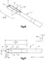
- the distal region 26 includes a tip 30 that defines the distal end 8 of the delivery body 4.
- the tip 30 can also be referred to as a "distal tip”, “leading tip”, and/or "insertion tip”.
- the tip 30 defines a maximum or first height H1.
- the tip 30 can also taper distally to a second height H2 that is less than the first height H1.
- the first height can be located at a second location 16b proximally spaced from the distal end 8, and the second height H2 can be located at the distal end 8.
- the tip 30 can taper distally to a point or a rounded distal end 8 that can have a nominal second height H2, or a second height H2 that is zero or substantially zero.
- the tip 30 can taper distally to a rounded or otherwise pointed nose 31 at the distal end 8.
- the first and second heights H1, H2 are each measured along a vertical direction Z that is perpendicular to the central axis 10 (and thus also perpendicular to the longitudinal direction X) and perpendicular to the lateral direction Y.
- the second direction Z is configured to coincide with the cranial-caudal direction C-C when the delivery body 4 is advanced within the patient. Accordingly, the second direction Z can also be referred to as a vertical direction Z.
- proximal refers to spacing along a proximal direction XP oriented along the longitudinal direction X from the distal end 8 to the proximal end 6.
- distal refers to spacing along a distal direction XD oriented along the longitudinal direction X from the proximal end 6 to the distal end 8. It should be appreciated that the proximal end distal directions XP, XD are each monodirectional components of the longitudinal direction X, which is bi-directional.
- the distal region 26 defines a first or superior contact surface 32 and a second or inferior contact surface 34 opposite each other along the second direction Z.
- the first and second contact surfaces 32, 34 are spaced from each other along the second direction Z by the first height H1.
- the first and second contact surfaces 32, 34 are configured to face, and optionally contact, the opposed endplates of the superior and inferior vertebral bodies, respectively.
- the distal region 26 can define a distance X2, measured along the longitudinal direction X from the distal end 8 of the delivery body 4 to a proximal end 35 of the first and second contact surfaces 32, 34.
- the first and second contact surfaces 32, 34 can each have a profile P1 that is substantially linear in a reference plane RP1 orthogonal to the central axis 10, as shown in Fig. 1E , although other profiles in the orthogonal reference plane RP1 are also within the scope of the present disclosure.
- the first and second contact surfaces 32, 34 can have a crowned (i.e., an arcuate, convex) profile in the orthogonal reference plane.
- the first and second contact surfaces 32, 34 can also each have a profile P2 that is substantially linear in a reference plane RP2 that extends along the central axis 10 (and thus along the longitudinal direction X) and the second direction Z.
- Figs. 2A through 2C one significant advantage provided by the design of the delivery bodies 4 disclosed herein is that the distal region 26 can be utilized as a trial member or portion 28 of the delivery body 4, as will now be described.
- the delivery body 4 can be provided in a kit system 99 that includes a plurality of delivery bodies 4a-n, each optionally being configured generally similarly to one another, and each for delivering biomaterial 9 to an intervertebral disc space 7 between a superior vertebral body 3a and an adjacent inferior vertebral body 3b.
- the delivery bodies 4a-n of the kit system 99 have respective trial portions 28a-n, which preferably each define at least one dimension, such as the maximum height H1, that is different than that of at least one other of the trial portions 28a-n.
- the at least one dimension can also include the length X2 of the trial portions 28a-n.
- the trial portions 28a-n can be configured to provide feedback to a physician at least regarding the spacing or "disc height" between the respective endplates 5a, b of the superior and inferior vertebral bodies 3a, b that define a disc space along the cranial-caudal direction C-C of the patient.
- the feedback provided by the trial portions 28a-n preferably includes visual feedback of the disc height.
- the trial portions 28a-n can be formed from a material that is visible under radiographic imaging, such as titanium, stainless steel, or the like.
- the at least one opening 14 of the trial portions 28a-n when viewed in conjunction with lateral and frontal X-rays, assists in the optimum positioning of the respective trial portion 28a-n relative to the superior and inferior vertebral bodies.
- the trial portions 28a-n can also include one or more markers or other features that are visible under radiographic imaging, such as fluoroscopy, for assisting in the optimal positioning of the trial portions 28a-n of the delivery bodies 4a-n.
- each trial portion 28a-n allows a physician to use one or more such trial portions 28a-n in succession to gauge the disc height.
- an additional advantage of these trial portion 28a-n is that the height of a subsequent intervertebral fusion cage can be determined during the biomaterial 9 delivery phase of a multi-phase intervertebral procedure, which can eliminate the need for a separate fusion cage height trialing step.
- the delivery body 4 can also include additional visual indicia, such as a series of hatch marks 23 having uniform spacing, such as at 5 mm or 10 mm increments, for example, provided on the outer surface 11 of the delivery body 4.
- the hatch marks 23 can be employed for indicating the depth at which the trial portion 28a-n engages the vertebra, as well as the depth at which the distal end 8 advances within the disc space.
- the hatch marks 23 can also be used in combination with radiographic imaging to ascertain the insertion depth to a target location of the disk space.
- One or more trial portions 28a-n of various sizes can be inserted and removed as needed, preferably along the same approach axis 25 (i.e., such that the central axis 10 of the delivery body 4 is substantially aligned with the approach axis 25), to gauge the appropriate size of the disc space 7, such as the disc height, and optionally also an insertion depth to a target location or reference location within the disc space, such as the intersection of the coronal midline CM and the sagittal midline SM, by way of a non-limiting example.
- the carrier 50 can be withdrawn from the cannulation, and a subsequent carrier 50 loaded with additional biomaterial 9 (or the same carrier 50 re-loaded with additional biomaterial 9) can be inserted in the cannulation 12, as before.
- the foregoing process can be repeated until the desired quantity of biomaterial 9 is delivered to the disc space.
- the delivery body 4 can be inserted through a retractor body, such as a retractor tube 500, that is supported by a spinal mounting assembly 600, as shown.
- the retractor tube 500 and spinal mounting assembly can be configured as more fully described in U.S. Patent Publication No.
- the push rod 73 can be driven distally, at least in part, by impacting the impaction pad 80 of the force transmission member 78 with an impaction hammer 89. Additionally, from the optical views, in combination with the sizing of the one or more trial portions 28a-n, the size of a subsequent intervertebral fusion cage can be chosen.
- trial portions 28a-n can be used for more than simply ascertaining the disc height between vertebral bodies 3a, 3b.
- the trial portions 28a-n can be used to determine whether the desired position of the intervertebral fusion cage is reachable, whether enough disc material has been removed, and the like.
- the instrument assemblies 2 described herein can also be employed to deliver the biomaterial 9 around or within a fusion cage that has been inserted within the disc space.
- an instrument assembly 2 in a spinal fusion procedure, can be employed to deliver a first quantity of the biomaterial 9 into the disc space 7 and the assembly 2 can be withdrawn therefrom; a fusion cage, such as an expandable fusion cage, can then be inserted to a desired position within the disc space 7 and expanded, such as along the cranial-caudal C-C direction; and the instrument assembly 2, having the same or a different delivery body 4a-n (or second portion 4t thereof) as before can be inserted back into the disc space 7 and can deliver an additional quantity of the biomaterial 9 around and/or within the fusion cage.
- a fusion cage such as an expandable fusion cage
- the delivery body 4 can be configured to expel the biomaterial 9 from one or more sides of the distal region 26, as well as axially therefrom.
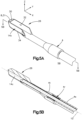
- the at least one opening 14 at the distal region 26 can include an axial opening 14a at the distal end 8 and a pair of opposed side openings 14b, c spaced from each other along a third or lateral direction Y perpendicular to the longitudinal direction X and the second direction Z.
- the distal region 26 can expel the biomaterial 9 distally, as well as laterally in opposite directions away from the central axis 10, from the delivery body 4 and into the disc space 7.
- the opposed side openings 14b, c can be proximally spaced from the axial opening 14a.
- the three openings 14a-c allow the biomaterial 9 to follow the path of least resistance from the delivery body 4 into the disc space, which can be particularly advantageous should one or two of the openings 14a-c be blocked or partially blocked, such as by disc material, such as an unremoved portion of the nucleus pulposus and/or anulus fibrosis.
- the distal region 26 of the present embodiment can be otherwise substantially similar to the that of the embodiments illustrated in Figs. 1E and 1F .
- the delivery body 4 can be configured to expel the biomaterial 9 in opposite directions laterally away from, but not distally from, the distal region 26.
- the least one opening 14 can include the pair of opposed side openings 14b, c without the axial opening 14a of the preceding embodiment, such that the distal end 8 of the delivery body 4 is closed in the longitudinal direction X.
- the delivery body 4 can include a diversion formation, such as a wedge formation 17 at a terminal distal end of the cannulation 12.
- the wedge formation 17 can be aligned along the central axis 10 between the pair of side openings 14b, c and can have an apex that faces proximally, with a pair of side surfaces 17a, b that are configured to divert the biomaterial 9 from the cannulation 12 laterally out the pair of opposed side openings 14b, c.
- the side surfaces 17a, b of the wedge formation 17 can be arcuate, as shown, or can be straight in other embodiments.
- the distal region 26 of the presently illustrated embodiment can be otherwise substantially similar to the distal regions 26 of the embodiments illustrated in Figs. 1E and 1F and Fig. 3 .
- the delivery body 4 can optionally be constructed of a material allowing the body 4 to elastically deform radially outward from the central axis 10 as the biomaterial 9 is pushed distally through the cannulation 12. In this manner, the delivery body 4 can be constructed with smaller dimensions in the lateral and vertical directions Y, Z and can employ the foregoing flexibility to avoid biomaterial 9 blockages therein. Thus, the delivery body 4 constructed in this manner can have an overall less invasive instrument profile.
- the delivery body 4 can include one or more support elements, such as support rods, which can be formed of steel, for example, and extend longitudinally along the delivery body 4 to maintain its structural integrity, such as to prevent, or at least substantially prevent, plastic deformation of the delivery body 4.
- the delivery body 4 can alternatively include a single side opening 14c that is open at least along the lateral direction Y.
- the single side opening 14c can also be elongate along, as well as open along, the longitudinal direction X.
- the distal region 26 can optionally include a diversion formation for diverting the biomaterial 9 from the cannulation 12 and out the single side opening 14b laterally into the disc space.
- the distal region 26 of the present embodiment can be otherwise similar to the distal regions 26 of the embodiments illustrated in Figs. 1E and 1F ; Fig. 3, and Figs. 4A and 4B .
- the distal region 26 can include a tip 30 that tapers distally to a rounded nose 31 at the distal end 8.
- the distal region 26 can include first and second contact surfaces 32, 34 opposite each other along the second direction Z.
- the first and second contact surfaces 32, 34 of the present embodiment can be spaced from each other by the maximum height H2, measured along the second direction Z, as in the embodiments described above.
- the delivery body 4 can also include a coupling 4r, such as a threaded coupling, for example, at which a first or proximal section 4s of the delivery body 4 couples with a separate second or distal section 4t of the delivery body 4.
- the proximal section 4s can include the mounting formation 18 and the distal section 4t can include the distal region 26 (and thus also the trail portion 28an).
- the trial portions 28a-n of the delivery bodies 4a-n described above can be provided in a kit system 99 that includes a plurality of the distal sections 4t that are of different size and are interchangeable with a first section 4s via the coupling 4r.
- the delivery bodies 4 of other embodiments of the present disclosure can include interchangeable second sections 4t and first portions 4s.
- the instrument assembly 2 can include additional instrumentation, such as a biomaterial retention mechanism 40, which can integral with the delivery body 4.
- the biomaterial retention mechanism 40 can be a monolithic proximal extension of the delivery body 4.
- the biomaterial retention mechanism 40 is configured to retain loaded biomaterial 9 within the instrument assembly 2, including within the cannulation 12, while the carrier 50 is withdrawn proximally from the delivery body 4 and the biomaterial retention mechanism 40. In this manner, the carrier 50 can be removed from the cannulation 12 before the advancement member 70 is inserted, which frees up space within the cannulation 12 and can reduce friction between the biomaterial 9 and the delivery body 4.
- the carrier 50 and advancement member 70 for use in the present embodiment can have respective longitudinal lengths greater than those in the embodiments above.
- the biomaterial retention mechanism 40 can be a separate component that is attachable to the delivery body 4.
- a distal end 43 of the biomaterial retention mechanism 40 can be configured to couple to the proximal mounting formation 18 of the delivery body 4, such that the biomaterial retention mechanism 40 extends proximally from the delivery body 4.
- the biomaterial retention mechanism 40 can be configured as an optional auxiliary instrument that can attach to and detach from the delivery body 4 as needed.
- the biomaterial retention mechanism 40 can include a proximal end 41 spaced from the distal end 43 along the longitudinal direction X.
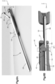
- the biomaterial retention mechanism 40 includes a switch, such as a latch 42, that includes an occlusion formation 44 having a shape complimentary with the shape of the carrier channel 52 in a reference plane RP1 orthogonal to the central axis 10.
- the latch 42 is configured to iterate between an open position (as shown in Fig. 6A ), in which the occlusion formation 44 is remote from the channel 52, and a closed position (as shown in Fig. 6B ), in which the occlusion formation 44 is positioned in the channel 52 proximally of at least some, and preferably a majority of, the biomaterial 9.
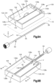
- the tray 122 can be rectangular and can have four sidewalls 128a-d successively arranged at right angles to one another about the periphery of the floor surface 126.
- the tray 122 can have a first sidewall 128a and a second sidewall 228b opposite each other along the longitudinal direction X, and a third sidewall 228c and a fourth sidewall 128d opposite each other along the lateral direction Y.
- One or more and up to all of the interior wall surfaces 130a-d can be sloped inwardly toward the floor surface 126, such as to facilitate directing the biomaterial 9 deposited on the tray 122 toward the slot 132. As shown, the interior wall surfaces 130a-d can slope arcuately toward the floor surface 126. It is to be appreciated that, during use, the biomaterial 9 can be deposited within the volume V, such as generally on the floor surface 126 and/or directly over the slot 132.
- the tray body 124 can define a plurality of elongate slots 132 for receiving a plurality of carriers 50 to be loaded with biomaterial 9.
- the tray body 124 can include two (2), three (3), four (4), five (5), or more than five (5) slots 132, each for receiving a respective carrier 50 therein.
- the tray 122 can be configured to load one or more and up to each of the plurality of carriers 50 with biomaterial 9, as needed.
- the floor surface 126 can define a plurality of floor surface portions vertically offset from one another in step- or terrace-like fashion on opposite sides of each of the slots 132, for facilitating moving the biomaterial 9 from the floor surface portions into the slots 132, as described above.
- the tray body 124 can also include a respective plurality of access ports 134 and/or carrier retention receptacles 137 in communication with the plurality of slots 132.
- the loading system can include an auxiliary tool 136 for moving biomaterial 9 from the volume V of the tray 122 into the carrier channel 52 inserted within the slot 132.
- the auxiliary tool 136 of the present embodiment is configured to be manually manipulated for depositing the biomaterial 9 within the carrier channel 52 inserted within the slot 132.
- the auxiliary tool 136 can include a handle 138 and a push member, such as a wiper or scraper 140, extending from the handle 138.
- the scraper 140 can be a blade having a scraping edge 141.
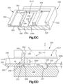
- the sidewalls 228a-c define respective inner surfaces 230a-c that, together with the floor surface 226, cooperatively define a first or primary volume V1 of space for receiving biomaterial 9.
- the primary volume V1 can also be referred to as the "tray volume" V1.
- the sidewalls 228a-c can include a first sidewall 228a, a second sidewall 228b opposite the first sidewall 228a along the longitudinal direction X, and a third sidewall 228c extending from the first sidewall to the second sidewall 228b along the longitudinal direction X.
- the tray body 224 can define an open end 229 opposite the third sidewall 228c with respect to the lateral direction Y. The open end 229 is configured to receive the moving mechanism 250.
- the slider body 252 preferably has a shape, as viewed in a horizontal reference plane RP4 extending along the longitudinal and lateral directions X, Y, that generally corresponds to the shape of the floor surface 226 in a respective horizontal reference plane RP4.
- the floor surface 226 and the slider body 252 can each have a generally rectangular shape in the horizontal reference plane RP4.
- the slider body 252 can define first and second slider endwalls 254, 256 opposite each other along the lateral direction Y.
- the slider body 252 can also define first and second slider sidewalls 258, 260 opposite each other along the longitudinal direction X and extending from the first slider endwall 254 to the second slider endwall 256.
- the push wall 262 has a bottom surface 266 that can be configured to iterate between a neutral orientation (as shown) and a deflected or flexed orientation.
- the bottom surface 266 has a geometry that, when in the neutral orientation, preferably is complimentary with a geometry of the floor surface 226.
- the bottom surface 266 can be planar and parallel with the floor surface 226.
- the push wall 262 can also include a wiper 268 configured to direct at least some of the biomaterial 9 from the secondary volume V2 into the slot 232, and thus into any carrier channel 52 loaded in the slot 232.
- the elevated floor surface portion such as the second floor surface portion 226b in the depicted embodiment, can overhang a portion of the slot 232 for further directing the biomaterial 9 into the slot 232 as the push wall 262 moves in the forward direction FD.
- the slot 232 of the present embodiment is open to, and thus in communication with, the primary and secondary volumes V1, V2, at least along the opening direction O, which is oriented along a slot opening axis 239.
- the opening direction O can be offset from the vertical direction Z by the acute slot opening angle A3 described above.
- the slot opening direction O can be aligned with the vertical direction Z.
- the slot 232 is preferably configured to retain the carrier 50 therein, such as with the carrier retention receptacle 237, so that the carrier channel 52 is also maintained open to the volumes V1, V2 along the opening direction O.
- the carrier retention receptacle 237, the offset distance H3, and the slot opening angle A3 are preferably cooperatively configured to cause the edges of the elongate channel opening 53 to be substantially aligned with the edges of the elongate slot opening 235, as described above.
- An example method of using the loading device 220 can include inserting the carrier 50 into the slot 232 so that the carrier channel 52 is open to the tray volume V1.
- a quantity of material 9 can be deposited within the secondary volume V2 and onto the floor surface 226, such as onto the first floor surface portion 226a thereof, before or after the carrier 50 is inserted within the slot 232.
- the slider body 252 With the carrier 50 disposed in the slot 232 and the channel 52 open along the opening direction O (or at least open to the volumes V1, V2), the slider body 252 can be slid in the forward direction FD across the floor surface 226 so that the push member 262 pushes biomaterial 9 downwardly into the slot 232, thereby loading at least some of the deposited biomaterial 9 into the slot 232.
- the push member 262 can be advanced forward so as to entirely traverse the slot 232 and cause the push member 262 to deflect upwards into the deflected orientation, whereby the push surface 270 and rear edge 272 can remove, such as by pushing away, biomaterial 9 extending outwardly from the carrier channel 52, thus further preparing the biomaterial 9 for optimum or at least favorable loading within the delivery body 4.
- the slider body 252 can then be slid in the rearward direction FR until the push member 262 is again located rearward of the slot 232 and in the neutral orientation. Any of the foregoing steps can be repeated as necessary until the carrier channel 52 is loaded with the biomaterial 9 in a desired manner.
- an auxiliary tool such as the auxiliary tool 136 described above, can be used to manually scrape, push, wipe, and/or tamp biomaterial 9 into the carrier channel 52, or remove excess biomaterial 9 from the carrier channel 52, following operation of the loading device 220 as needed.
- the carrier 50 can then be removed from the slot 232 and subsequently loaded within the cannulation 12 of the delivery body 4, as described above. After the carrier 50 is removed from the slot 232, a subsequent carrier 50 can be inserted therein and loaded with biomaterial 9 in similar fashion.
- One advantage of the loading devices described herein is that they are configured for repeated loading of a plurality of carriers 50.
- the tray body 224 can define a plurality of elongate slots 232 for receiving a plurality of carriers 50 to be loaded with biomaterial 9 simultaneously or at least substantially simultaneously.
- the tray body 224 can include two (2), three (3), four (4), five (5), or more than five (5) slots 232, each for receiving a respective carrier 50 therein.
- the tray 222 can be configured to load one or more and up to each of the plurality of carriers 50 simultaneously or at least substantially simultaneously with biomaterial 9, as needed.
- the floor surface 226 can define a plurality of floor surface portions extending respectively between adjacent slots 232.
- These floor surface portions can be aligned along a common incline plane, from which the push surface 270 is offset at the back rake angle A4.
- the push surface 270 is configured to push biomaterial 9 successively into the slots 232 as the push member 262 moves in the forward direction FD.
- the common incline plane can allow the back rake angle A4 of the push surface 270 to be maintained as the push surface traverses the slots 232 in the forward and rearward directions FD, RD.
- the tray body 224 can also include a respective plurality of access ports 234 and/or carrier retention receptacles 237 in communication with the plurality of slots 232.
- a loading device 320 can include a tray 322 having one or more slots 332 for receiving the elongate body portions 55 of corresponding one or more carriers 50, and a rotary mechanism 350 for directing biomaterial 9 into the one or more slots 332.
- the tray 322 comprises a tray body 324 that defines a first or top tray surface 326.
- the one or more slots 332 are recessed within the tray body 324 from the top tray surface 326 along the vertical direction Z.
- the loading device 320 includes a housing 328 that at least partially defines an internal volume V configured for receiving biomaterial 9 ( Fig. 11B ).
- the tray body 324 can define carrier retention receptacles at distal ends of the slot 332 for retaining the carriers 50 such that the carrier channels 52 remain open to the internal volume V, similarly as described above with reference to other embodiments. It is also to be appreciated that the tray body 324 can include more than two (2) slots 332, including three (3), four (4), five, (5), six (6) seven (7), eight (8), nine (9), ten (10), or more than ten (10) slots 332, for example.
- the size of the loading device 320 including the size of the tray body 324, can be scaled upward or downward in size as necessary to accommodate as many or as few slots 332 needed for a particular biomaterial-loading application. In multi-slot embodiments, the loading device 320 can include one or more slot inserts 359 ( Fig. 11A ) for occupying any unused slots 332, thus preventing the biomaterial 9 from filling the unused slots during use of the device.
- the rotary mechanism 350 includes a push member, such as a rotary disk 362, that is configured to move biomaterial 9 deposited within the internal volume V into the one or more slots 332 as the rotary disk 362 rotates about an axis of rotation 353.
- the rotary disk 362 includes one or more pusher features, such as wipers 364 on an underside 366 of the rotary disk 362 opposite a top surface 365 of the rotary disk 362.
- the wipers 364 are configured to push biomaterial 9 within the internal volume V across the top surface 326 of the tray body 324 and into the one or more slots 332, as described in more detail below.
- One or more and up to all of the wipers 364 can be elongate along respective central wiper axes 363 that are linear and extend along a horizontal reference plane RP4 (i.e., a reference plane orthogonal to the vertical direction Z).
- One or more and up to all of the central wiper axes 363 can be offset from a radial direction R perpendicular to the axis of rotation 353. That is to say, one or more and up to all of the central wiper axes 363 can be skewed from (i.e., not intersect) the axis of rotation 353.
- one or more and up to all of the central wiper axes 363 can extend along a respective radial direction R that intersects the axis of rotation 353.
- one or more and up to all of the central wiper axes 363 can be curved in the horizontal reference plane RP4. It should be appreciated that the wiper axes 363 are oriented relative to the slot axes 333 for effective movement of biomaterial 9 into the slots 332.
- the axis of rotation 353 can be centrally defined by a spindle 355.
- the spindle 355 can be separate from, and coupled to, the rotary disk 362, as shown; although in other embodiments the spindle 355 and the rotary disk 362 can be monolithic with each other.
- a control member such as a handle 367, can be coupled to the rotary disk 362 and configured to drive rotation of the rotary disk 362 about the axis of rotation 353.
- the handle 367 can extend, for example, from the top surface 365 of the rotary disk 362.
- the housing 328 can define a disk receptacle 368 in which the rotary disk 362 resides.
- the disk receptacle 368 can extend downwardly from, and be at partially defined by, a top surface 370 of the housing 328.
- the housing 328 can also define a base surface 372 recessed below the top housing surface 370 and defining a base of the disk receptacle 368.
- the base surface 372 also defines a base surface of the internal volume V.
- the loading device 320 can include one or more inlets 376 each providing communication from an exterior of the device 320 into the internal volume V.
- the inlets 376 can be defined by the rotary disk 362 and can extend from the top surface 365 to the underside 366 of the disk, particularly a portion of the underside 366 offset from the one or more wipers 364.
- the inlets 376 can each be at least partially defined by an inlet formation 378 that extends vertically upwards from the top surface 365 of the rotary disk 362.
- the inlet formation 376 can be characterized as a "hopper" configured to hold biomaterial 9 prior to the biomaterial 9 being directed into the internal volume V.
- An inlet cap 380 can be configured to cover the inlet 376.
- the cap 380 can include a handle portion 381 and protrusion 382 extending downwardly from the handle portion 381 and having a complimentary geometry with the inlet 376.
- the cap 380 can be configured so that the protrusion 382 extends within the inlet 376 for pushing biomaterial 9 into the internal volume V.
- the cap 380 can also be configured such that a bottom surface 382a of the protrusion 382 abuts the top surface 326 of the tray body 324 when the handle portion 381 abuts the inlet formation 378.
- the cap 380 can be employed as a tamp member to tamp biomaterial 9 into the one or more slots 332 as needed when the rotary disk 362 positions the cap 380 over the one or more slots 332.
- a cover 384 can be configured to couple with the inlet formation 378 and cover the cap 380.
- a biasing member such as a spring 383, can operatively couple the cap 380 to the cover 384, and can be configured to bias the bottom surface 382a of the protrusion 382 against the top surface 326 of the tray body 324 so as to force biomaterial 9 downward into the one or more slots 332 when the cover is coupled with the inlet formation 378.
- the cap 380 and cover 384 can be detached from the inlet formation 378 when it is desired to deposit biomaterial 9 within the inlet 376, and can be subsequently coupled to the inlet formation 378 to provide a constant downward force for pushing the deposited biomaterial 9 into the one or more slots 332.
- the loading device 320 can include two or more such inlets 376 located on the rotary disk 362 so that a pair of inlets 376 are spaced from each other about the circumference of the rotary disk 362, such as on opposite sides of the axis of rotation 353. In this manner, the rotary disk 362 can be rotated so as to locate one of the inlets 376 over the base surface 372 of the housing 328 and the other inlet 376 over the tray 322, such as over the one or more slots 332 thereof.
- Such an inlet design provides flexibility in the use and operation of the loading device 320.
- one of the inlets 376 can be used for depositing biomaterial 9 within the internal volume, while the other inlet 376, particularly the cap 380 thereof, can optionally be used as a tamp for tamping biomaterial 9 within the one or more slots 332. It is to be appreciated that other inlet 376 configurations are within the scope of the present disclosure.
- the wipers 364 extend downwardly from the rotary disk 362 and contact, or at least be in close proximity to, the base surface 372 of the housing 328, such that rotation of the rotary disk 362 causes the wipers 364 to move biomaterial 9 across the base surface 372 and/or across the top surface 326 of the tray 322, in one or both of a first rotational direction RD1 and a second rotational direction RD2 about the axis of rotation 353, and into the one or more slots 332.
- a first rotational direction RD1 and a second rotational direction RD2 about the axis of rotation 353, and into the one or more slots 332.
- one or more and up to all of the wipers 364 can have a bottom wiper surface 371, as well as opposed first and second side wiper surfaces 369a, b that extend downwardly from the underside 366 of the rotary disk 362 to the bottom wiper surface 371.
- One or both of the side wiper surfaces 369a, b can taper inwardly from the underside 366 to the bottom wiper surface 371 at a taper angle A5, as measured with respect to a vertical axis 385 in a reference plane orthogonal to the central wiper axis 363.
- the taper angle A5 advantageously causes the respective side wiper surface 369a, b to direct the biomaterial 9 downwardly into the one or more slots 322 as the wiper 364 traverses the one or more slots 332. It is to be appreciated that, on one or more and up to all of the wipers 364, the taper angle A5 of the first side wiper surface 369a can be different than that of the second side wiper surface A5.
- One or more and up to all of the wipers 364 can be comprised of a flexible material having a low hardness, as measured by a durometer, which provides the wiper(s) 364 with flexibility, as described above.
- One or more and up to all of the wipers 364 can optionally be monolithic with the rotary disk 362.
- the rotary disk 362 and the wipers 364 can be monolithically formed of a flexible material having a low hardness.
- the rotary mechanism 350 can comprise an actuation assembly, such as a gear assembly 386, for translating the tray 322 along a forward direction FD relative to the housing 328 as the rotary disk 362 rotates about the axis 353 along the first rotational direction RD1, and also along a rearward direction RD as the rotary disk 362 rotates about the 353 along the second rotational direction RD2.
- the gear assembly 386 is configured such that the wipers 364 will move substantially against the direction FD, RD at which the tray body 324 moves, regardless of whether the rotary disk 362 rotates in the first or second rotational direction RD1, RD2.
- the gear assembly 386 can include a spindle gear 388 that rotates with the spindle 355 and drives a pinion 390, which, in turn, is configured to drive a rack 392 defined by, or carried by, the tray body 324.
- the loading device 320 can translate the tray 322, along with any carriers 50 inserted therein, through the internal volume V and beneath the wipers 364, so as to deposit biomaterial 9 into the carrier channels 52.
- the gear assembly 386 can also include an intermediate gear 394 having teeth 395 that intermesh with teeth 389 of the spindle gear 388.
- the pinion 390 can extend from, and have a gear axis 397 common with, the intermediate gear 394.
- the pinion 390 has teeth 391 that intermesh with teeth 393 of the rack 392.
- the gear assembly 386 can employ a gear ratio that is selected for maximizing loading of the biomaterial 9 within the one or more carrier channels 52. It is to be appreciated that the gear assembly 386 can employ gear configurations different than that shown in the present embodiment.
- the drive member 470 is configured to engage the auger 452, such as via complimentary engagement features, in a manner such that rotation of the drive member 470 about the central axis 453 also rotates the auger 452 about the central axis 453.
- the auger 452 and the drive member 470 can be coupled together, such as by press-fitting, heat shrinking, adhesives, and/or mechanical fasteners and the like.
- the drive member 470 can also define an inner surface 474 opposite the outer surface 472.
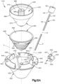
- the inner surface 426 of the housing body 424 and the outer surface 454 of the auger 452 preferably have complimentary inverted frusto-conical shapes about the central axis 453.
- the inner surface 474 of the drive member 470 defines a drive member chamber 476.
- the drive member 470 defines a drive coupling 478, which can be a post centrally located within the drive member chamber 476 and extending along the central axis 453.
- the drive coupling 478 can have one or more formations for transmitting a rotational drive force to the drive member 470 and thus also to the auger 452.
- One such formation can include knurls or teeth 480 on an exterior of the drive coupling 478.
- the teeth 480 can provide grip facilitating manual rotation of the drive member 470 about the central axis 453.
- the drive coupling 478 can also be referred to as a "rotary handle".
- the teeth 480 can also be configured to intermesh with one or more complimentary teeth of a drive tool.
- Another such formation can include a socket 482 extending downwardly from an upper end of the drive coupling and configured to receive a complimentary drive tool, such as a drive bit of a manual driver or a powered driver, by way of non-limiting examples. It is to be appreciated that other types and configurations of the drive coupling 478 are within the scope of the present disclosure for driving rotation of the drive member 470.
- the central post 434 can extend upwardly along the vertical direction Z from a base surface 436 of the housing body 424.
- the base surface 436 defines a bottom end of the chamber 430.
- the base surface 436, as well as the inner surface 426, are configured for receiving the biomaterial 9 within the internal volume V, as described in more detail below.
- the housing body 424 defines the one or more slots 432, which are recessed radially outward from the inner surface 426 with respect to the central axis 453 and are in communication with the internal volume V.
- the one or more slots 432 can be characterized as being defined within the inner surface 426.
- the one or more slots 432 each extend along a respective slot axis 433.
- the housing body 424 preferably has a plurality of slots 432, which can be spaced equidistantly about the circumference of the inner surface 426.
- the one or more slots 432 are each configured such that the elongate body portions 55 of the carriers 50 can be inserted within the slot 432 along the central slot axis 433.
- the one or more slots 432 and the carrier 50 are cooperatively configured such that the central axis 10 of the carrier 50 is substantially coincident with the central slot axis 433.
- the one or more slots 432 can extend to, and be at least partially defined by, the base surface 436.
- the housing body 424 can define carrier retention receptacles at distal ends of the slot 432 for retaining the carriers 50 therein such that the carrier channels 52 remain open to the internal volume V, similarly as described above with reference to other embodiments.
- the housing body 424 defines five (5) slots 432; however in other embodiments the housing body 424 can define more than five slots (5) slots 432, such as six (6), seven (7), eight (8), nine (9), ten (10), or more than ten (10) slots 432.
- the housing body 424 can also define less than five slots, such as four (4), three (3), or two (2) slots 432 or one (1) single slot 432. It is to be appreciated that the circumference of the housing body 424 can be scaled upward or downward in size as necessary to accommodate as many slots 432 as needed for a particular biomaterial-loading application.
- the housing 422 can also define a rim structure 440 for receiving the stop members 60 of the carriers 50.
- the rim structure 440 can define one or more respective rim openings 442 for receiving an insert 441.
- the rim structure 440 can include rails or platforms 444 located in the rim openings 442 for engaging complimentary slots 443 defined in the sides of the inserts 441.
- the inserts 441 can be said to fit within the associated rim openings 442 in "dovetail" fashion.
- the insert 441 can have a support surface 445 for supporting the distal surfaces 64 of the stop members 60.
- the insert 441 can also include a tamp member, such as a roller 447, which can be received within an insert opening 449 defined by the insert 441.
- the insert 441 is configured such that, when it resides within the associated rim opening 442, the elongate body portion 55 of the carrier 50 can be inserted into and withdrawn from the slot 432 through the insert opening 449.
- the roller 447 is configured to engage the edges of the elongate channel opening 53, whereby the roller 447 can tamp or press the biomaterial 9 loaded within the channel 52 as the carrier 50 is withdrawn, thereby also removing any excess material 9 from the carrier 50.
- the roller 447 is preferably comprised of a flexible material having a low hardness, such as those materials described above.
- the rim structure 440 can also define an inner rim surface 446 that has a substantially cylindrical configuration.
- the inner rim surface 446 can be configured to interface with an outer cylindrical surface 484 of the drive member 470, such as to cooperatively provide the loading device 410 with a supplemental journal bearing mechanism.
- the outer cylindrical surface 484 of the drive member 470 can also engage inner surfaces of the inserts 441 so as to retain the inserts 441 within the rim openings 442 during operation of the loading device 410.
- a single insert 441 is shown in Fig. 12A , it should be appreciated that the loading device 410 can include a plurality of inserts 441, including an insert 441 for each of the rim openings 442.
- the rotary mechanism 450 can be configured for quick and repeated detachment from and re-attachment with the housing 424.
- the auger 452 and the drive member 470 coupled together as described above, can rest freely in the chamber 430 of the housing body 424, and can be configured to be lifted together manually by gripping the rotary handle 478 and lifting upward.
- biomaterial 9 can be deposited in the chamber 430, such as on the base surface 436, and the rotary mechanism 450 can be re-attached to the housing body 424, such as by inserting the rotary handle 478 over the central post 434 of the housing body 424.
- the rotary handle 478 can be manually rotated (or rotated under power), thereby driving the external thread 456 about the central axis 453, in turn causing the thread 456 to move the biomaterial 9 upwardly along the inner surface 426 of the housing body 424.
- the external thread 456 moves the biomaterial 9 from the internal volume V and into one or more carrier channels 52 disposed respectively within the one or more slots 432.
- the external thread 456 can define a crest that can abut, or at least be in close proximity to, the inner surface 426 as well as the base surface 436, and can thus be configured to scrape, wipe, push, or otherwise direct biomaterial 9 from the internal volume V into the one or more slots 432.
- the loading device 410 defines a direction of axial advancement Z1 that is oriented along the central axis 453 and upward along the vertical direction Z.
- the depicted loading device 410 is configured to move the deposited biomaterial 9 away from the base surface 436 and upwardly along the inner surface 426 and into the one or more slots 432.
- the direction of axial advancement Z1 can be downward in the vertical direction Z, whereby the loading device 410 can be configured to move biomaterial 9 from a base surface at or near a top of the housing 422 and downward along the inner surface 426 and into the one or more slots 432.
- Other configurations are also within the scope of the present disclosure.
- the central post 434 of the housing 422 can extend within a central bore 486 of the drive member 470.
- the auger 452 can include a base portion 460 at a bottom end thereof that interfaces with the base surface 436 of the housing body 424.
- the base portion 460 of the auger 452 can define a central base aperture 462 through which the central post 436 of the housing body 424 extends.
- the drive member 470 can define a base portion 487 at the bottom end thereof that interfaces with the base portion 460 of the auger 452.
- the drive member 470 can also define a mounting structure, such as a bushing 488, that extends through the central base aperture 462 of the auger 452 and can extend to, and interface with, the base surface 436 of the housing body 424.
Landscapes
- Health & Medical Sciences (AREA)
- Orthopedic Medicine & Surgery (AREA)
- Life Sciences & Earth Sciences (AREA)
- Surgery (AREA)
- Biomedical Technology (AREA)
- Engineering & Computer Science (AREA)
- Animal Behavior & Ethology (AREA)
- Heart & Thoracic Surgery (AREA)
- General Health & Medical Sciences (AREA)
- Public Health (AREA)
- Veterinary Medicine (AREA)
- Nuclear Medicine, Radiotherapy & Molecular Imaging (AREA)
- Transplantation (AREA)
- Medical Informatics (AREA)
- Molecular Biology (AREA)
- Physical Education & Sports Medicine (AREA)
- Cardiology (AREA)
- Oral & Maxillofacial Surgery (AREA)
- Vascular Medicine (AREA)
- Neurology (AREA)
- Biophysics (AREA)
- Prostheses (AREA)
- Surgical Instruments (AREA)
Applications Claiming Priority (3)
| Application Number | Priority Date | Filing Date | Title |
|---|---|---|---|
| US16/441,951 US11298242B2 (en) | 2019-06-14 | 2019-06-14 | Biomaterial delivery device, and related systems and methods |
| PCT/EP2020/065383 WO2020249443A2 (en) | 2019-06-14 | 2020-06-03 | Biomaterial delivery device, and related systems and methods |
| EP20732785.9A EP3982860B1 (de) | 2019-06-14 | 2020-06-03 | Biomaterialabgabevorrichtungen und zugehörige systeme |
Related Parent Applications (2)
| Application Number | Title | Priority Date | Filing Date |
|---|---|---|---|
| EP20732785.9A Division EP3982860B1 (de) | 2019-06-14 | 2020-06-03 | Biomaterialabgabevorrichtungen und zugehörige systeme |
| EP20732785.9A Division-Into EP3982860B1 (de) | 2019-06-14 | 2020-06-03 | Biomaterialabgabevorrichtungen und zugehörige systeme |
Publications (2)
| Publication Number | Publication Date |
|---|---|
| EP4527319A2 true EP4527319A2 (de) | 2025-03-26 |
| EP4527319A3 EP4527319A3 (de) | 2025-06-04 |
Family
ID=71094296
Family Applications (2)
| Application Number | Title | Priority Date | Filing Date |
|---|---|---|---|
| EP25156099.1A Pending EP4527319A3 (de) | 2019-06-14 | 2020-06-03 | Vorrichtung zur abgabe von biomaterial sowie entsprechende systeme und verfahren |
| EP20732785.9A Active EP3982860B1 (de) | 2019-06-14 | 2020-06-03 | Biomaterialabgabevorrichtungen und zugehörige systeme |
Family Applications After (1)
| Application Number | Title | Priority Date | Filing Date |
|---|---|---|---|
| EP20732785.9A Active EP3982860B1 (de) | 2019-06-14 | 2020-06-03 | Biomaterialabgabevorrichtungen und zugehörige systeme |
Country Status (6)
| Country | Link |
|---|---|
| US (2) | US11298242B2 (de) |
| EP (2) | EP4527319A3 (de) |
| JP (1) | JP7480188B2 (de) |
| CN (2) | CN114007534B (de) |
| AU (1) | AU2020293549A1 (de) |
| WO (1) | WO2020249443A2 (de) |
Families Citing this family (8)
| Publication number | Priority date | Publication date | Assignee | Title |
|---|---|---|---|---|
| US11298242B2 (en) * | 2019-06-14 | 2022-04-12 | Medos International Sarl | Biomaterial delivery device, and related systems and methods |
| JP2022551122A (ja) | 2019-10-04 | 2022-12-07 | ペインテク、エルエルシー | 仙腸関節を融合するための器具 |
| US11058550B2 (en) | 2019-10-04 | 2021-07-13 | Pain TEQ, LLC | Allograft implant for fusing a sacroiliac joint |
| US11154402B1 (en) | 2019-10-04 | 2021-10-26 | Pain TEQ, LLC | Instrumentation for fusing a sacroiliac joint |
| US12171669B2 (en) | 2020-10-09 | 2024-12-24 | Spinal Elements, Inc. | Systems and methods for filling material |
| US11931053B2 (en) | 2022-08-04 | 2024-03-19 | PTL Opco, LLC | Single-use joint decorticator apparatus |
| CN115770096A (zh) * | 2022-11-14 | 2023-03-10 | 深圳大学 | 椎体扩张器及压缩骨折椎体治疗套件 |
| JPWO2024241545A1 (de) * | 2023-05-24 | 2024-11-28 |
Citations (1)
| Publication number | Priority date | Publication date | Assignee | Title |
|---|---|---|---|---|
| US20180008253A1 (en) | 2015-09-04 | 2018-01-11 | Medos International Sarl | Multi-Shield Spinal Access System |
Family Cites Families (63)
| Publication number | Priority date | Publication date | Assignee | Title |
|---|---|---|---|---|
| WO1998028068A1 (en) * | 1996-12-13 | 1998-07-02 | Norian Corporation | Preparation, storage and administration of cements |
| KR100717224B1 (ko) | 2000-04-05 | 2007-05-11 | 키폰 인크. | 골절되거나 병든 뼈를 치료하는 방법 및 장치 |
| JP2003529438A (ja) | 2000-04-07 | 2003-10-07 | カイフォン インコーポレイテッド | 挿入デバイスおよびその使用方法 |
| KR100889414B1 (ko) * | 2000-06-27 | 2009-03-20 | 키폰 에스에이알엘 | 유동성 재료를 뼈 안으로 주입하는 시스템 및 방법 |
| US7025771B2 (en) | 2000-06-30 | 2006-04-11 | Spineology, Inc. | Tool to direct bone replacement material |
| DE60140558D1 (de) | 2000-10-25 | 2009-12-31 | Kyphon S A R L | Systeme zur reposition von gebrochenen knochen mittels einer kanüle zur reponierung von knochenfrakturen |
| US7544196B2 (en) | 2001-02-20 | 2009-06-09 | Orthovita, Inc. | System and kit for delivery of restorative materials |
| US6676663B2 (en) * | 2001-07-19 | 2004-01-13 | Higueras Antonio Perez | Applicator device for controllably injecting a surgical cement into bones |
| FR2829690B1 (fr) | 2001-09-19 | 2003-12-19 | Inoteb | Dispositif de mise en place d'un biomateriau |
| GB2382028B (en) | 2001-11-19 | 2006-11-01 | Aberdeen Orthopaedic Developme | Intervertebral disc prosthesis |
| US7294132B2 (en) | 2002-10-03 | 2007-11-13 | Wright Medical Technology, Inc. | Radially ported needle for delivering bone graft material and method of use |
| US20070043376A1 (en) | 2003-02-21 | 2007-02-22 | Osteobiologics, Inc. | Bone and cartilage implant delivery device |
| WO2004093750A2 (en) | 2003-04-23 | 2004-11-04 | The Cleveland Clinic Foundation | Apparatus for depositing bone grafting material |
| EP1691848B1 (de) | 2003-10-23 | 2012-08-22 | TRANS1, Inc. | Werkzeuge und werkzeugsets zur durchführung von minimalinvasiven verfahren an der wirbelsäule |
| US7722612B2 (en) | 2004-05-19 | 2010-05-25 | Sintea Biotech S.P.A. | Devices, kit and method for kyphoplasty |
| SE527528C2 (sv) | 2004-06-22 | 2006-04-04 | Bone Support Ab | Anordning för framställning av härdbar massa samt användning av anordningen |
| US7722620B2 (en) | 2004-12-06 | 2010-05-25 | Dfine, Inc. | Bone treatment systems and methods |
| US8092464B2 (en) * | 2005-04-30 | 2012-01-10 | Warsaw Orthopedic, Inc. | Syringe devices and methods useful for delivering osteogenic material |
| EP1903961B1 (de) | 2005-07-07 | 2012-05-16 | Crosstrees Medical, Inc. | Vorrichtung zur abgabe von füllstoffen für knochenlücken |
| US8540723B2 (en) * | 2009-04-14 | 2013-09-24 | Dfine, Inc. | Medical system and method of use |
| US9867646B2 (en) | 2006-04-07 | 2018-01-16 | Gamal Baroud | Integrated cement delivery system for bone augmentation procedures and methods |
| GB2437783B (en) * | 2006-04-26 | 2011-11-02 | Summit Medical Ltd | A medical treatment material delivery apparatus |
| US20070260258A1 (en) * | 2006-05-05 | 2007-11-08 | Robert Sommerich | Access and delivery needle for percutaneous vertebroplasty |
| US20080091207A1 (en) | 2006-10-13 | 2008-04-17 | Csaba Truckai | Bone treatment systems and methods |
| US8241295B2 (en) * | 2007-09-05 | 2012-08-14 | Wolf Ii Erich W | Apparatus and method for the dispensing of bone cement |
| US7883511B2 (en) | 2007-09-12 | 2011-02-08 | Fernyhough Jeffrey C | Method and composition for use in reinforcing bone |
| CA2703062A1 (en) | 2007-10-29 | 2009-05-07 | Tigenix Limited | Implant delivery device and method |
| US20090149878A1 (en) | 2007-12-07 | 2009-06-11 | Csaba Truckai | Bone treatment systems and methods |
| KR100892766B1 (ko) | 2008-09-11 | 2009-04-15 | 이달호 | 골조직 이식을 위한 주사기용 본 인퓨저 |
| US20100198140A1 (en) | 2009-02-05 | 2010-08-05 | Kevin Jon Lawson | Percutaneous tools and bone pellets for vertebral body reconstruction |
| US8241298B2 (en) | 2009-03-27 | 2012-08-14 | Depuy Mitek, Inc. | Methods and devices for delivering and affixing tissue scaffolds |
| US20170238984A1 (en) | 2009-09-18 | 2017-08-24 | Spinal Surgical Strategies, Llc | Bone graft delivery device with positioning handle |
| US9060877B2 (en) * | 2009-09-18 | 2015-06-23 | Spinal Surgical Strategies, Llc | Fusion cage with combined biological delivery system |
| US8894658B2 (en) | 2009-11-10 | 2014-11-25 | Carefusion 2200, Inc. | Apparatus and method for stylet-guided vertebral augmentation |
| CH702815A1 (de) * | 2010-03-10 | 2011-09-15 | Medmix Systems Ag | Befüllvorrichtung zum Befüllen mindestens eines ersten Reservoirs eines Applikators. |
| US20120065694A1 (en) | 2010-06-11 | 2012-03-15 | Simonson Peter M | Wedge shaped catheter balloons for repair of damaged vertebra |
| US8408250B2 (en) | 2010-06-18 | 2013-04-02 | Warsaw Orthopedic, Inc. | Bone replacement material mixing and delivery devices and methods of use |
| US20120065613A1 (en) * | 2010-08-27 | 2012-03-15 | Pepper John R | Methods and Systems for Interbody Implant and Bone Graft Delivery |
| US8394129B2 (en) | 2011-03-10 | 2013-03-12 | Interventional Spine, Inc. | Method and apparatus for minimally invasive insertion of intervertebral implants |
| US9101429B2 (en) * | 2011-04-27 | 2015-08-11 | Jiin-Huey Chern Lin | Method and apparatus for delivering cement paste into a bone cavity |
| US8932295B1 (en) | 2011-06-01 | 2015-01-13 | Surgical Device Exchange, LLC | Bone graft delivery system and method for using same |
| CN103841927A (zh) | 2011-06-09 | 2014-06-04 | 齐默尔膝部创造物公司 | 用于软骨下关节修复的器械和装置 |
| EP2734122B1 (de) * | 2011-07-20 | 2018-05-30 | Stryker Corporation | Rohrverzweigung zum abfüllen mehrerer kanulen |
| WO2013127406A1 (en) * | 2012-02-29 | 2013-09-06 | Stryker Trauma Gmbh | System for handling an augmentation implant |
| US9192420B2 (en) | 2013-01-24 | 2015-11-24 | Kyphon Sarl | Surgical system and methods of use |
| US20140257489A1 (en) | 2013-03-11 | 2014-09-11 | Interventional Spine, Inc. | Method and apparatus for minimally invasive insertion of intervertebral implants |
| US9668881B1 (en) * | 2013-03-15 | 2017-06-06 | Surgentec, Llc | Bone graft delivery system and method for using same |
| US9393057B2 (en) | 2013-10-08 | 2016-07-19 | Pioneer Surgical Technology, Inc. | Surgical system and method |
| EP3075359B1 (de) | 2013-10-23 | 2017-11-22 | Stryker European Holdings I, LLC | System zur perkutanen knochenimplantateinführung |
| US9668876B2 (en) | 2013-12-05 | 2017-06-06 | Spinal Elements, Inc. | Expandable interbody device |
| US9351739B2 (en) | 2013-12-31 | 2016-05-31 | Amendia, Inc. | Tunneling device |
| US10993707B2 (en) | 2014-10-17 | 2021-05-04 | Cervos Medical Llc | Bone marrow aspiration device and method |
| DE202014008486U1 (de) * | 2014-10-27 | 2016-01-28 | Mathys Ag Bettlach | Vorrichtung zum Applizieren von Knochenersatzpasten |
| US10022243B2 (en) | 2015-02-06 | 2018-07-17 | Benvenue Medical, Inc. | Graft material injector system and method |
| US9730773B2 (en) | 2015-04-22 | 2017-08-15 | Maxillent Ltd. | Bone graft injection methods |
| US20170164978A1 (en) | 2015-12-09 | 2017-06-15 | Laurian Mark Dean | Delivery Device and Method For Vertebroplasty and Kyphoplasty Procedures |
| GB2550848A (en) | 2016-05-23 | 2017-12-06 | Cattalytic Solutions Ltd | Bone Cement Mixer |
| GB201614011D0 (en) * | 2016-08-16 | 2016-09-28 | Sky Light Medical Ltd | Improved surgical tool |
| US10231846B2 (en) * | 2016-08-19 | 2019-03-19 | Stryker European Holdings I, Llc | Bone graft delivery loading assembly |
| US10709576B2 (en) * | 2017-04-28 | 2020-07-14 | Warsaw Orthopedic, Inc. | Bone material dispensing apparatus and methods |
| CN111031947A (zh) * | 2017-08-24 | 2020-04-17 | 诺信公司 | 用于输送医用材料的方法和装置 |
| US10869770B2 (en) * | 2017-12-11 | 2020-12-22 | Stryker European Holdings I, Llc | Bone graft delivery revolver |
| US11298242B2 (en) * | 2019-06-14 | 2022-04-12 | Medos International Sarl | Biomaterial delivery device, and related systems and methods |
-
2019
- 2019-06-14 US US16/441,951 patent/US11298242B2/en active Active
-
2020
- 2020-06-03 CN CN202080043572.1A patent/CN114007534B/zh active Active
- 2020-06-03 EP EP25156099.1A patent/EP4527319A3/de active Pending
- 2020-06-03 EP EP20732785.9A patent/EP3982860B1/de active Active
- 2020-06-03 JP JP2021573856A patent/JP7480188B2/ja active Active
- 2020-06-03 CN CN202411270264.9A patent/CN118902588A/zh active Pending
- 2020-06-03 AU AU2020293549A patent/AU2020293549A1/en not_active Abandoned
- 2020-06-03 WO PCT/EP2020/065383 patent/WO2020249443A2/en not_active Ceased
-
2022
- 2022-03-14 US US17/694,086 patent/US12433766B2/en active Active
Patent Citations (1)
| Publication number | Priority date | Publication date | Assignee | Title |
|---|---|---|---|---|
| US20180008253A1 (en) | 2015-09-04 | 2018-01-11 | Medos International Sarl | Multi-Shield Spinal Access System |
Also Published As
| Publication number | Publication date |
|---|---|
| US12433766B2 (en) | 2025-10-07 |
| WO2020249443A3 (en) | 2021-03-04 |
| JP2022535995A (ja) | 2022-08-10 |
| US20200390566A1 (en) | 2020-12-17 |
| JP7480188B2 (ja) | 2024-05-09 |
| CN114007534A (zh) | 2022-02-01 |
| CN118902588A (zh) | 2024-11-08 |
| EP4527319A3 (de) | 2025-06-04 |
| AU2020293549A1 (en) | 2022-02-10 |
| US20220192843A1 (en) | 2022-06-23 |
| EP3982860A2 (de) | 2022-04-20 |
| CN114007534B (zh) | 2024-10-11 |
| WO2020249443A2 (en) | 2020-12-17 |
| US11298242B2 (en) | 2022-04-12 |
| EP3982860B1 (de) | 2025-04-23 |
Similar Documents
| Publication | Publication Date | Title |
|---|---|---|
| EP3982860B1 (de) | Biomaterialabgabevorrichtungen und zugehörige systeme | |
| US12121456B2 (en) | Graft material injector system and method | |
| US12213886B2 (en) | Systems, devices, and methods for joint fusion | |
| US10492928B2 (en) | Angling inserter tool for expandable vertebral implant | |
| US8292958B1 (en) | Spinal cage having deployable member | |
| US8100972B1 (en) | Spinal cage having deployable member | |
| JP5656997B2 (ja) | 同軸スクリューギアスリーブ機構を用いた椎体伸延および固定のための装置 | |
| EP2705809A1 (de) | Vorrichtungen für Rückenmarksgewebedistraktion | |
| EP2327377A1 (de) | Radial expandierende Zwischenwirbelfusionsimplantate und Instrumente zum Einsetzen dieser Implantate | |
| WO2008103781A2 (en) | Devices for treating the spine | |
| AU2011200592A1 (en) | Systems and methods for spinal surgery | |
| EP1572040A2 (de) | Implantat zum einsatz bei versteifungsoperationen an der wirbelsäule | |
| US20250248715A1 (en) | Systems, devices, and methods for preparing bone to receive an implant | |
| US7578823B2 (en) | Delivery tool and method for delivering bone growth material | |
| US20220133490A1 (en) | Methods and Implants for Facet Joint Stabilization or Fusion |
Legal Events
| Date | Code | Title | Description |
|---|---|---|---|
| PUAI | Public reference made under article 153(3) epc to a published international application that has entered the european phase |
Free format text: ORIGINAL CODE: 0009012 |
|
| STAA | Information on the status of an ep patent application or granted ep patent |
Free format text: STATUS: THE APPLICATION HAS BEEN PUBLISHED |
|
| AC | Divisional application: reference to earlier application |
Ref document number: 3982860 Country of ref document: EP Kind code of ref document: P |
|
| AK | Designated contracting states |
Kind code of ref document: A2 Designated state(s): AL AT BE BG CH CY CZ DE DK EE ES FI FR GB GR HR HU IE IS IT LI LT LU LV MC MK MT NL NO PL PT RO RS SE SI SK SM TR |
|
| PUAL | Search report despatched |
Free format text: ORIGINAL CODE: 0009013 |
|
| AK | Designated contracting states |
Kind code of ref document: A3 Designated state(s): AL AT BE BG CH CY CZ DE DK EE ES FI FR GB GR HR HU IE IS IT LI LT LU LV MC MK MT NL NO PL PT RO RS SE SI SK SM TR |
|
| RIC1 | Information provided on ipc code assigned before grant |
Ipc: A61B 17/88 20060101ALI20250425BHEP Ipc: A61F 2/46 20060101ALI20250425BHEP Ipc: A61F 2/28 20060101ALI20250425BHEP Ipc: A61B 17/02 20060101AFI20250425BHEP |
|
| STAA | Information on the status of an ep patent application or granted ep patent |
Free format text: STATUS: REQUEST FOR EXAMINATION WAS MADE |
|
| 17P | Request for examination filed |
Effective date: 20251119 |
|
| GRAP | Despatch of communication of intention to grant a patent |
Free format text: ORIGINAL CODE: EPIDOSNIGR1 |
|
| STAA | Information on the status of an ep patent application or granted ep patent |
Free format text: STATUS: GRANT OF PATENT IS INTENDED |
|
| INTG | Intention to grant announced |
Effective date: 20260130 |