EP4523939A1 - Elektrisches raupenfahrzeug - Google Patents
Elektrisches raupenfahrzeug Download PDFInfo
- Publication number
- EP4523939A1 EP4523939A1 EP24198559.7A EP24198559A EP4523939A1 EP 4523939 A1 EP4523939 A1 EP 4523939A1 EP 24198559 A EP24198559 A EP 24198559A EP 4523939 A1 EP4523939 A1 EP 4523939A1
- Authority
- EP
- European Patent Office
- Prior art keywords
- electric motor
- rotational speed
- turning
- traveling
- electric
- Prior art date
- Legal status (The legal status is an assumption and is not a legal conclusion. Google has not performed a legal analysis and makes no representation as to the accuracy of the status listed.)
- Pending
Links
Images


Classifications
-
- B—PERFORMING OPERATIONS; TRANSPORTING
- B62—LAND VEHICLES FOR TRAVELLING OTHERWISE THAN ON RAILS
- B62D—MOTOR VEHICLES; TRAILERS
- B62D55/00—Endless track vehicles
- B62D55/08—Endless track units; Parts thereof
- B62D55/12—Arrangement, location, or adaptation of driving sprockets
- B62D55/125—Final drives
-
- B—PERFORMING OPERATIONS; TRANSPORTING
- B62—LAND VEHICLES FOR TRAVELLING OTHERWISE THAN ON RAILS
- B62D—MOTOR VEHICLES; TRAILERS
- B62D55/00—Endless track vehicles
- B62D55/06—Endless track vehicles with tracks without ground wheels
- B62D55/062—Tracked vehicles of great dimensions adapted for moving bulky loads or gear
-
- B—PERFORMING OPERATIONS; TRANSPORTING
- B60—VEHICLES IN GENERAL
- B60K—ARRANGEMENT OR MOUNTING OF PROPULSION UNITS OR OF TRANSMISSIONS IN VEHICLES; ARRANGEMENT OR MOUNTING OF PLURAL DIVERSE PRIME-MOVERS IN VEHICLES; AUXILIARY DRIVES FOR VEHICLES; INSTRUMENTATION OR DASHBOARDS FOR VEHICLES; ARRANGEMENTS IN CONNECTION WITH COOLING, AIR INTAKE, GAS EXHAUST OR FUEL SUPPLY OF PROPULSION UNITS IN VEHICLES
- B60K17/00—Arrangement or mounting of transmissions in vehicles
- B60K17/28—Arrangement or mounting of transmissions in vehicles characterised by arrangement, location, or type of power take-off
-
- B—PERFORMING OPERATIONS; TRANSPORTING
- B62—LAND VEHICLES FOR TRAVELLING OTHERWISE THAN ON RAILS
- B62D—MOTOR VEHICLES; TRAILERS
- B62D11/00—Steering non-deflectable wheels; Steering endless tracks or the like
- B62D11/02—Steering non-deflectable wheels; Steering endless tracks or the like by differentially driving ground-engaging elements on opposite vehicle sides
- B62D11/06—Steering non-deflectable wheels; Steering endless tracks or the like by differentially driving ground-engaging elements on opposite vehicle sides by means of a single main power source
- B62D11/10—Steering non-deflectable wheels; Steering endless tracks or the like by differentially driving ground-engaging elements on opposite vehicle sides by means of a single main power source using gearings with differential power outputs on opposite sides, e.g. twin-differential or epicyclic gears
-
- B—PERFORMING OPERATIONS; TRANSPORTING
- B60—VEHICLES IN GENERAL
- B60K—ARRANGEMENT OR MOUNTING OF PROPULSION UNITS OR OF TRANSMISSIONS IN VEHICLES; ARRANGEMENT OR MOUNTING OF PLURAL DIVERSE PRIME-MOVERS IN VEHICLES; AUXILIARY DRIVES FOR VEHICLES; INSTRUMENTATION OR DASHBOARDS FOR VEHICLES; ARRANGEMENTS IN CONNECTION WITH COOLING, AIR INTAKE, GAS EXHAUST OR FUEL SUPPLY OF PROPULSION UNITS IN VEHICLES
- B60K1/00—Arrangement or mounting of electrical propulsion units
- B60K1/02—Arrangement or mounting of electrical propulsion units comprising more than one electric motor
-
- B—PERFORMING OPERATIONS; TRANSPORTING
- B60—VEHICLES IN GENERAL
- B60K—ARRANGEMENT OR MOUNTING OF PROPULSION UNITS OR OF TRANSMISSIONS IN VEHICLES; ARRANGEMENT OR MOUNTING OF PLURAL DIVERSE PRIME-MOVERS IN VEHICLES; AUXILIARY DRIVES FOR VEHICLES; INSTRUMENTATION OR DASHBOARDS FOR VEHICLES; ARRANGEMENTS IN CONNECTION WITH COOLING, AIR INTAKE, GAS EXHAUST OR FUEL SUPPLY OF PROPULSION UNITS IN VEHICLES
- B60K17/00—Arrangement or mounting of transmissions in vehicles
- B60K17/04—Arrangement or mounting of transmissions in vehicles characterised by arrangement, location or kind of gearing
- B60K17/043—Transmission unit disposed in on near the vehicle wheel, or between the differential gear unit and the wheel
- B60K17/046—Transmission unit disposed in on near the vehicle wheel, or between the differential gear unit and the wheel with planetary gearing having orbital motion
-
- B—PERFORMING OPERATIONS; TRANSPORTING
- B60—VEHICLES IN GENERAL
- B60K—ARRANGEMENT OR MOUNTING OF PROPULSION UNITS OR OF TRANSMISSIONS IN VEHICLES; ARRANGEMENT OR MOUNTING OF PLURAL DIVERSE PRIME-MOVERS IN VEHICLES; AUXILIARY DRIVES FOR VEHICLES; INSTRUMENTATION OR DASHBOARDS FOR VEHICLES; ARRANGEMENTS IN CONNECTION WITH COOLING, AIR INTAKE, GAS EXHAUST OR FUEL SUPPLY OF PROPULSION UNITS IN VEHICLES
- B60K17/00—Arrangement or mounting of transmissions in vehicles
- B60K17/04—Arrangement or mounting of transmissions in vehicles characterised by arrangement, location or kind of gearing
- B60K17/06—Arrangement or mounting of transmissions in vehicles characterised by arrangement, location or kind of gearing of change-speed gearing
- B60K17/08—Arrangement or mounting of transmissions in vehicles characterised by arrangement, location or kind of gearing of change-speed gearing of mechanical type
-
- B—PERFORMING OPERATIONS; TRANSPORTING
- B60—VEHICLES IN GENERAL
- B60K—ARRANGEMENT OR MOUNTING OF PROPULSION UNITS OR OF TRANSMISSIONS IN VEHICLES; ARRANGEMENT OR MOUNTING OF PLURAL DIVERSE PRIME-MOVERS IN VEHICLES; AUXILIARY DRIVES FOR VEHICLES; INSTRUMENTATION OR DASHBOARDS FOR VEHICLES; ARRANGEMENTS IN CONNECTION WITH COOLING, AIR INTAKE, GAS EXHAUST OR FUEL SUPPLY OF PROPULSION UNITS IN VEHICLES
- B60K35/00—Instruments specially adapted for vehicles; Arrangement of instruments in or on vehicles
- B60K35/20—Output arrangements, i.e. from vehicle to user, associated with vehicle functions or specially adapted therefor
- B60K35/28—Output arrangements, i.e. from vehicle to user, associated with vehicle functions or specially adapted therefor characterised by the type of the output information, e.g. video entertainment or vehicle dynamics information; characterised by the purpose of the output information, e.g. for attracting the attention of the driver
-
- B—PERFORMING OPERATIONS; TRANSPORTING
- B62—LAND VEHICLES FOR TRAVELLING OTHERWISE THAN ON RAILS
- B62D—MOTOR VEHICLES; TRAILERS
- B62D11/00—Steering non-deflectable wheels; Steering endless tracks or the like
- B62D11/001—Steering non-deflectable wheels; Steering endless tracks or the like control systems
- B62D11/003—Electric or electronic control systems
-
- B—PERFORMING OPERATIONS; TRANSPORTING
- B62—LAND VEHICLES FOR TRAVELLING OTHERWISE THAN ON RAILS
- B62D—MOTOR VEHICLES; TRAILERS
- B62D11/00—Steering non-deflectable wheels; Steering endless tracks or the like
- B62D11/02—Steering non-deflectable wheels; Steering endless tracks or the like by differentially driving ground-engaging elements on opposite vehicle sides
- B62D11/06—Steering non-deflectable wheels; Steering endless tracks or the like by differentially driving ground-engaging elements on opposite vehicle sides by means of a single main power source
- B62D11/10—Steering non-deflectable wheels; Steering endless tracks or the like by differentially driving ground-engaging elements on opposite vehicle sides by means of a single main power source using gearings with differential power outputs on opposite sides, e.g. twin-differential or epicyclic gears
- B62D11/14—Steering non-deflectable wheels; Steering endless tracks or the like by differentially driving ground-engaging elements on opposite vehicle sides by means of a single main power source using gearings with differential power outputs on opposite sides, e.g. twin-differential or epicyclic gears differential power outputs being effected by additional power supply to one side, e.g. power originating from secondary power source
- B62D11/16—Steering non-deflectable wheels; Steering endless tracks or the like by differentially driving ground-engaging elements on opposite vehicle sides by means of a single main power source using gearings with differential power outputs on opposite sides, e.g. twin-differential or epicyclic gears differential power outputs being effected by additional power supply to one side, e.g. power originating from secondary power source the additional power supply being supplied mechanically
-
- B—PERFORMING OPERATIONS; TRANSPORTING
- B62—LAND VEHICLES FOR TRAVELLING OTHERWISE THAN ON RAILS
- B62D—MOTOR VEHICLES; TRAILERS
- B62D55/00—Endless track vehicles
- B62D55/06—Endless track vehicles with tracks without ground wheels
- B62D55/065—Multi-track vehicles, i.e. more than two tracks
-
- B—PERFORMING OPERATIONS; TRANSPORTING
- B60—VEHICLES IN GENERAL
- B60K—ARRANGEMENT OR MOUNTING OF PROPULSION UNITS OR OF TRANSMISSIONS IN VEHICLES; ARRANGEMENT OR MOUNTING OF PLURAL DIVERSE PRIME-MOVERS IN VEHICLES; AUXILIARY DRIVES FOR VEHICLES; INSTRUMENTATION OR DASHBOARDS FOR VEHICLES; ARRANGEMENTS IN CONNECTION WITH COOLING, AIR INTAKE, GAS EXHAUST OR FUEL SUPPLY OF PROPULSION UNITS IN VEHICLES
- B60K2360/00—Indexing scheme associated with groups B60K35/00 or B60K37/00 relating to details of instruments or dashboards
- B60K2360/16—Type of output information
- B60K2360/161—Explanation of functions, e.g. instructions
-
- B—PERFORMING OPERATIONS; TRANSPORTING
- B60—VEHICLES IN GENERAL
- B60K—ARRANGEMENT OR MOUNTING OF PROPULSION UNITS OR OF TRANSMISSIONS IN VEHICLES; ARRANGEMENT OR MOUNTING OF PLURAL DIVERSE PRIME-MOVERS IN VEHICLES; AUXILIARY DRIVES FOR VEHICLES; INSTRUMENTATION OR DASHBOARDS FOR VEHICLES; ARRANGEMENTS IN CONNECTION WITH COOLING, AIR INTAKE, GAS EXHAUST OR FUEL SUPPLY OF PROPULSION UNITS IN VEHICLES
- B60K2360/00—Indexing scheme associated with groups B60K35/00 or B60K37/00 relating to details of instruments or dashboards
- B60K2360/16—Type of output information
- B60K2360/171—Vehicle or relevant part thereof displayed
-
- B—PERFORMING OPERATIONS; TRANSPORTING
- B60—VEHICLES IN GENERAL
- B60Y—INDEXING SCHEME RELATING TO ASPECTS CROSS-CUTTING VEHICLE TECHNOLOGY
- B60Y2200/00—Type of vehicle
- B60Y2200/20—Off-Road Vehicles
- B60Y2200/25—Track vehicles
Definitions
- the present invention relates to an electric crawler vehicle.
- Patent Document 1 Japanese Unexamined Patent Publication No. 2020-011591
- both the left and right electric motors need to be configured by electric motors that generate large power for traveling of the vehicle, which leads to an increase in cost and in size of the vehicle.
- the present invention was made in order to solve the aforementioned problems, and an object of the present invention is to realize an inexpensive and compact electric crawler vehicle.
- An electric crawler vehicle includes a pair of left and right traveling crawlers, each having a drive wheel, a traveling electric motor that generates traveling power to be transmitted to the pair of left and right traveling crawlers, a turning electric motor that generates turning power to be transmitted to the pair of left and right traveling crawlers, and a differential mechanism disposed in a power transmission path between the turning electric motor and each of the drive wheels of the pair of left and right traveling crawlers.
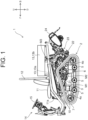
- FIG. 1 is a side view illustrating a schematic configuration of an electric crawler 1, which is an example of an electric crawler vehicle of this Embodiment. Note that, hereinafter, the electric crawler 1 may be simply referred to as a vehicle.
- a direction in which an operator (manipulator, driver) seated in a driver's seat 11 of the electric crawler 1 faces forward is defined as a front, and a direction opposite thereto is defined as a rear.
- the left side as viewed from the operator seated in the driver's seat 11 is referred to as "left” and the right side as “right”.
- a gravity direction perpendicular to a front-rear direction and a left-right direction is defined as an up-down direction
- an upstream side in the gravity direction is defined as "up”
- a downstream side is defined as "down”.
- the electric crawler 1 includes traveling crawlers 2 on left and right.
- Each of the traveling crawlers 2 includes a track frame 3 extending in the front-rear direction.
- a front-side driven sprocket also referred to as a front idler
- a rear-side driven sprocket 4b also referred to as a rear idler
- a plurality of rolling wheels 5 are rotatably supported between the front-side driven sprocket 4a and the rear-side driven sprocket 4b.
- a drive sprocket 6 is disposed as a drive wheel.
- a crawler belt 7 is wound around the drive sprocket 6, the front-side driven sprocket 4a, the rear-side driven sprocket 4b, and the plurality of rolling wheels 5 to constitute the traveling crawler 2.
- the electric crawler 1 includes a pair of left and right traveling crawlers 2, each having the drive wheel (drive sprocket 6).
- the electric crawler 1 includes a main body frame 10.
- the aforementioned track frame 3 is located below the main body frame 10 and is connected to the main body frame 10.
- a driver's seat 11 is disposed above the main body frame 10 via a seat mount 11a.
- a safety frame 12 is erected behind the driver's seat 11.
- a battery unit 13a is disposed in a space between the main body frame 10 and the driver's seat 11. Further, a battery unit 13b is disposed above the main body frame 10 and behind the safety frame 12.
- Electronic components such as a system controller 56 (see FIG. 5 ) to be described later are disposed above the battery unit 13b. Note that the battery unit 13a and the battery unit 13b are collectively referred to also as a battery unit 13 below.
- a floor (not shown) is provided on the front below the driver's seat 11.
- the floor is supported by the main body frame 10.
- a steering unit 14 is provided on the front side of the floor.
- a steering wheel 15 for turning the vehicle a lever for switching between forward and backward movement of the vehicle, a Power Take Off (PTO) switching lever, a brake pedal, and the like are provided.
- PTO Power Take Off
- a transmission case 21 (gear case, first speed reducer) is disposed between the pair of left and right traveling crawlers 2.
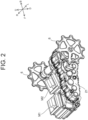
- FIG. 2 is a perspective view of transmission case 21.
- FIG. 3 is a perspective view of an inside of the transmission case 21.
- a traveling electric motor M1 and a turning electric motor M2 are connected to the transmission case 21.
- the traveling electric motor M1 is located on the front of the turning electric motor M2.
- a plurality of gears and chains or belts are provided between the drive shaft of the traveling electric motor M1 and the drive shafts of the left and right traveling crawlers 2.
- the traveling power generated by the traveling electric motor M1 is transmitted to the drive shafts of the left and right traveling crawlers 2 by the plurality of gears and the chains or the belts. Further, the plurality of gears are provided between the drive shaft of the turning electric motor M2 and the drive shafts of the left and right traveling crawlers 2, and turning power generated by the turning electric motor M2 is transmitted to the drive shafts of the left and right traveling crawlers 2 by the plurality of gears.
- the aforementioned drive sprockets 6 are provided at both left and right ends of the drive shafts of the left and right traveling crawlers 2. The drive sprocket 6 is rotated by the traveling power or the turning power transmitted to the drive shaft, whereby the left and right traveling crawlers 2 travel or turn.
- the electric crawler 1 includes a differential mechanism 30 (see FIG. 4 ), and details of the differential mechanism 30 will be described later.
- the electric crawler 1 of this Embodiment includes the traveling electric motor M1 that generates traveling power to be transmitted to the pair of left and right traveling crawlers 2, and the turning electric motor M2 that generates turning power to be transmitted to the pair of left and right traveling crawlers 2.
- the PTO electric motor M3 is supported on the rear part of the main body frame 10 shown in FIG. 1 .
- the PTO electric motor M3 is connected to a PTO power transmission unit 22 (second speed reducer) having a plurality of gears therein.
- a work machine 24 is connected to a rear part of the main body frame 10 via a two-point or three-point link-type elevating device 23.
- the work machine 24 can be driven by transmitting the power of the PTO electric motor M3 to the work machine 24 via the PTO power transmission unit 22.
- the work machine 24 is constituted by, for example, a tilling work machine (for example, a rotary tilling machine or a plow), but may be other work machines such as a fertilizing device.
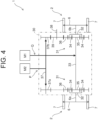
- FIG. 4 is an explanatory view schematically illustrating a configuration of a differential mechanism 30 included in the electric crawler 1.
- the differential mechanism 30 is disposed in a turning power transmission unit P (power transmission path) between the turning electric motor M2 and each drive wheel (drive sprocket 6) of the pair of left and right traveling crawlers 2.
- the differential mechanism 30 includes a pair of left and right planetary transmission mechanisms 31.
- the planetary transmission mechanisms 31 are disposed symmetrically.
- Each planetary transmission mechanism 31 has a planetary carrier 32, respectively.
- the left and right planetary carriers 32 are rotatably disposed in the transmission case 21 (see FIG. 3 ) such that a sun shaft 33 extending in the left-right direction and a center axis (rotation axis) are located coaxially.
- the center axis of the left-side planetary carrier 32 is connected to the drive shaft 6a of the drive wheel (drive sprocket 6) of the left-side traveling crawler 2.
- the center axis of the right-side planetary carrier 32 is connected to the drive shaft 6b of the drive wheel (drive sprocket 6) of the right-side traveling crawler 2.
- Each of the left and right planetary transmission mechanisms 31 has a plurality of (for example, three) planetary gears 34.
- each of the plurality of planetary gears 34 is rotatably supported by the left-side planetary carrier 32.
- each of the plurality of planetary gears 34 is rotatably supported by the right-side planetary carrier 32.
- the plurality of planetary gears 34 are positioned with the same radius around the sun shaft 33 and are disposed so as to mesh with sun gears 35 fixed to both left and right ends of the sun shaft 33, respectively.
- a ring gear 36 is disposed concentrically with the aforementioned sun shaft 33.
- Each ring gear 36 has internal teeth on its inner peripheral surface and external teeth on its outer peripheral surface.
- the ring gear 36 of the left-side planetary transmission mechanism 31 is disposed such that the internal teeth thereof mesh with the plurality of left-side planetary gears 34.
- the ring gear 36 of the right-side planetary transmission mechanism 31 is disposed such that the internal teeth thereof mesh with the plurality of right-side planetary gears 34.
- Each of the ring gears 36 is rotatably supported on the sun shaft 33 or on the drive shafts 6a and 6b via bearings.
- the rotational power (turning power) of the turning electric motor M2 is transmitted to the left-side drive shaft 6a and the right-side drive shaft 6b via the turning power transmission unit P. More specifically, the turning power of the turning electric motor M2 is transmitted to transmission gears 37a and 37b attached to both the left and right ends of a motor-output shaft 37.
- the left-side transmission gear 37a is disposed so as to directly mesh with external teeth of the left-side ring gear 36.
- the right-side transmission gear 37b is disposed so as to mesh with a reverse gear 39 attached to a reversing shaft 38.
- This reverse gear 39 is disposed so as to mesh with the outer teeth of the right-side ring gear 36.
- the sun shaft 33 and the sun gears 35 on both the left and right sides are fixed. Therefore, when the turning electric motor M2 (motor-output shaft 37) is rotated in the forward direction, the left-side ring gear 36 rotates in the reverse direction by a predetermined number of rotations (rotational speed), and the right-side ring gear 36 rotates in the forward direction at the same number of rotations as the left-side ring gear 36.
- the planetary gear 34 and the planetary carrier 32 on the left side rotate reversely about the sun shaft 33, while the planetary gear 34 and the planetary carrier 32 on the right side rotate forward about the sun shaft 33.
- the drive shaft 6a coaxial with the left-side planetary carrier 32 rotates in the reverse direction, while the drive shaft 6b coaxial with the right-side planetary carrier 32 rotates in the forward direction.
- the left-side traveling crawler 2 moves backward, and the right-side traveling crawler 2 moves forward.
- the electric crawler 1 spins and turns to the left on the spot.
- the traveling electric motor M1 when the traveling electric motor M1 is rotated, the rotational power (traveling power) of the traveling electric motor M1 is transmitted to the sun shaft 33 via the traveling power transmission unit Q.
- the traveling power transmission unit Q is configured to include a plurality of gears, a belt, and the like.
- the turning electric motor M2 is stopped in advance, for example, the rotation of the ring gears 36 on both the left and right sides is stopped and is brought into a fixed state. Therefore, the traveling power transmitted to the sun shaft 33 is equally transmitted to the left-side drive shaft 6a and the right-side drive shaft 6b via the left and right planetary transmission mechanisms 31 (the sun gears 35, the planetary gears 34, and the planetary carriers 32).
- the left and right drive sprockets 6 rotate in the same rotational direction at the same rotational speed, and the electric crawler 1 travels. That is, the electric crawler 1 moves forward or backward in accordance with the rotational direction of the traveling electric motor M1.
- the rotational speeds and rotational directions of the traveling electric motor M1 and the turning electric motor M2 are combined and controlled as appropriate, whereby the electric crawler 1 can be turned while traveling.
- the rotational speed and the rotational direction of the traveling electric motor M1 can be adjusted by an accelerator pedal and a lever for switching forward / backward traveling of the steering unit 14 (see FIG. 1 ).
- the rotational speed and the rotational direction of the turning electric motor M2 can be adjusted by the rotational direction and a rotational angle of the steering wheel 15 (see FIG. 1 ).
- the left and right traveling crawlers 2 can be driven separately by the left and right electric motors, whereby the following effects can be obtained as compared with a left / right independent driving method of performing traveling and turning of a vehicle.
- the turning electric motor M2 only needs to be a motor capable of generating power that causes a rotation difference (torque difference) between the left and right drive wheels (drive sprockets 6).
- the turning electric motor M2 does not have to have the same specification as that of the traveling electric motor M1 that needs to generate a large power for traveling. That is, an electric motor having an output lower than that of the traveling electric motor M1 can be used as the turning electric motor M2.
- an inexpensive and compact electric crawler 1 can be realized.
- the traveling speed and the turning radius can be adjusted in a stepless manner so as to perform smooth turning.
- either one of the left and right drive wheels is not rapidly decelerated any more during turning.
- a road surface for example, a field
- the traveling crawler 2 on the turning outer side is not driven by an excessive power to overcome the brake of the traveling crawler 2 on the turning inner side, or the horsepower of the traveling crawler 2 on the turning inner side does not remain any more. That is, the traveling electric motor M1 and the turning electric motor M2 can be driven to the necessary minimum and the generated traveling power and turning power can be used without waste, so that the energy efficiency can be improved.
- the maximum output of the turning electric motor M2 is set to, for example, 0.9 times or less of the maximum output of the traveling electric motor M1.
- the maximum output of the turning electric motor M2 may be set to 0.8 times or less of the maximum output of the traveling electric motor M1 or may be set to 0.7 times or less. From the viewpoint of reliably realizing an inexpensive and compact electric crawler 1, it is desirable that the maximum output of the turning electric motor M2 is smaller than the maximum output of the traveling electric motor M1.
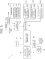
- FIG. 5 is a block diagram schematically illustrating a configuration of the control system of the electric crawler 1.
- the electric crawler 1 includes a charger 51, an inverter 52, a relay box 53, a high-voltage branch box 54, a DC-DC converter 55, the system controller 56, a high-voltage battery 57, and a lead battery (12V battery) 58, in addition to the traveling electric motor M1, the turning electric motor M2, and the PTO electric motor M3 described above.
- the system controller 56 is constituted by an electronic control unit, also referred to as an Electronic Control Unit (ECU), and executes electrical control of each part of the electric crawler 1.
- the high-voltage battery 57 corresponds to the battery unit 13 shown in FIG. 1 .
- the traveling electric motor M1, the turning electric motor M2, and the PTO electric motor M3 are driven by electric power supplied from the high-voltage battery 57 via the relay box 53, the high-voltage branch box 54, and the inverter 52.
- the charger 51 (also referred to as a power feeder) converts an AC voltage supplied from a commercial power supply (not shown) via a power feeding cable into a DC voltage.
- the inverter 52 converts a DC voltage supplied from the high-voltage battery 57 into an AC voltage and supplies it to the traveling electric motor M1 and the like. As a result, the traveling electric motor M1 and the like are rotated.
- the supply of the AC voltage (current) from the inverter 52 to the traveling electric motor M1 and the like is performed on the basis of a rotation command (command value) output from the system controller 56.
- the relay box 53 is a battery control unit that configured to include a battery relay and a fuse, and controls the battery relay so as to control an input and an output of the high-voltage battery 57.
- the high-voltage branch box 54 is configured to include a charger relay, an inverter relay, a fuse, and the like. The voltage output from the aforementioned charger 51 is supplied to the high-voltage battery 57 via the high-voltage branch box 54 and the relay box 53. As a result, the high-voltage battery 57 can be charged. The voltage output from the high-voltage battery 57 is supplied to the inverter 52 via the relay box 53 and the high-voltage branch box 54.
- the DC-DC converter 55 steps down a direct-current voltage of a high voltage (for example, 300V) supplied from the high-voltage battery 57 via the high-voltage branch box 54 to a low voltage (for example, 12V).
- a high voltage for example, 300V
- a low voltage for example, 12V.
- the voltage output from the DC-DC converter 55 is supplied to the system controller 56 or the like in the same manner as the output from the lead battery 58.
- the traveling electric motor M1 incorporates a traveling rotational speed sensor SE1.
- the traveling rotational speed sensor SE1 is constituted by, for example, an encoder, and detects an actual rotational speed of the motor-output shaft of the traveling electric motor M1. Information detected by the traveling rotational speed sensor SE1, that is, information on the rotational speed of the traveling electric motor M1 is input to the system controller 56.
- the turning electric motor M2 incorporates a turning rotational speed sensor SE2.
- the turning rotational speed sensor SE2 is constituted by, for example, an encoder, and detects the actual rotational speed of the motor-output shaft of the turning electric motor M2. Information detected by the turning rotational speed sensor SE2, that is, information on the rotational speed of the turning electric motor M2 is input to the system controller 56.
- the PTO electric motor M3 incorporates a PTO rotational speed sensor SE3.
- the PTO rotational speed sensor SE3 is constituted by, for example, an encoder, and detects the actual rotational speed of the motor-output shaft of the PTO electric motor M3. Information detected by the PTO rotational speed sensor SE3, that is, information on the rotational speed of the PTO electric motor M3 is input to the system controller 56.
- the electric crawler 1 further includes an alarm unit 60 that issues an alarm.
- the alarm unit 60 is disposed in the vicinity of the steering unit 14 or the driver's seat 11.
- the alarm unit 60 is configured to include a display unit 61, a sound output unit 62, and a light emitting unit 63.
- the display unit 61 is constituted by a monitor including a liquid crystal display device, for example. On the display unit 61, an alarm information is displayed, for example. That is, the electric crawler 1 includes the display unit 61 that displays information.
- the sound output unit 62 is constituted by a buzzer, a speaker, or the like, for example, and outputs the alarm information by voice or sound.
- the light emitting unit 63 is constituted by a LED lamp, for example, and lights or flashes at the alarm.
- the electric crawler 1 further includes a right-side sensor 71SR and a left-side sensor 71SL.
- the right-side sensor 71SR and the left-side sensor 71SL are constituted by encoders, for example.
- the right-side sensor 71SR detects the rotational speed of the rotating shaft (drive shaft 6b) of the drive wheel of the right-side traveling crawler 2.
- the left-side sensor 71SL detects the rotational speed of the rotating shaft (drive shaft 6a) of the drive wheel of the left-side traveling crawler 2.
- the electric crawler 1 includes a transmission / reception unit (not shown) and can communicate with the outside via the transmission / reception unit. As a result, an operation signal can be transmitted from the outside to the electric crawler 1, and the electric crawler 1 can be made to travel automatically by remote control. In addition, various types of information detected by the electric crawler 1 can be transmitted to an external management device, and a state of the electric crawler 1 (presence or absence of a failure, for example) can be remotely monitored by the management device.
- FIG. 6 is an explanatory view illustrating a power transmission path in a case where the traveling electric motor M1 is driven, and the electric crawler 1 is moving forward.
- the turning electric motor M2 is not driven and is in a free state.
- the differential lock state is brought about, and the drive wheels of the left and right traveling crawlers 2 rotate in the same direction at the same rotational speed.
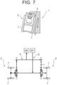
- FIG. 7 is an explanatory view illustrating a power transmission path when the right-side traveling crawler 2 of the electric crawler 1 is caught in mud and idles.
- the turning electric motor M2 When the right-side traveling crawler 2 idles, the turning electric motor M2 is rotated from the foot and may rotate excessively beyond the allowable rotational speed.
- the phrase that "the turning electric motor M2 is rotated from the foot” means that the turning electric motor M2 is rotated by the power transmitted from one of the drive wheels of the traveling crawler 2 that is idling via the power transmission path (the turning power transmission unit P). That is, when the right-side traveling crawler 2 idles, the differential operates, and the rotational power of the left-side traveling crawler 2 is transferred to the right-side traveling crawler 2.
- the left-side traveling crawler 2 stops, while the drive wheel of the right-side traveling crawler 2 rotates at a rotational speed twice as high as that when traveling at a predetermined speed.
- the turning electric motor M2 rotates at an overspeed. There is a concern that the overspeed of the turning electric motor M2 leads to breakage of the turning electric motor M2.
- the following control is executed to avoid the overspeed of the turning electric motor M2 and to prevent the breakage of the turning electric motor M2.
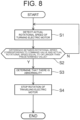
- FIG. 8 is a flowchart illustrating a flow of an operation according to an example of control to avoid overspeed of the turning electric motor M2 (hereinafter, also referred to as overspeed avoidance control).
- the system controller 56 determines whether or not a difference between a rotational speed RC (1/min) of the turning electric motor M2 corresponding to the command value output to the inverter 52 and the actual rotational speed RR is equal to or larger than a fixed value Rth (1/min) (S2).
- the command value is set by the operator in accordance with the rotational angle and the rotational direction of the steering wheel 15. If the difference between the actual rotational speed RR and the rotational speed RC is less than the fixed value Rth (No at S2), the processing returns to S1, and the operation at S1 and after is repeated.
- the system controller 56 determines that there is an abnormality (S3) and then, outputs a command value to the inverter 52 so as to stop the rotation of the traveling electric motor M1 (S4).
- the electric crawler 1 of this Embodiment includes the turning rotational speed sensor SE2 as a rotational speed sensor that detects the actual rotational speed RR of the turning electric motor M2.
- the electric crawler 1 includes the system controller 56 as a control unit that generates a command value for controlling the rotational speed RC of the turning electric motor M2.
- the system controller 56 determines that there is an abnormality, some measures can be taken. In terms of determining whether or not a subsequent countermeasure is necessary, as described above, the system controller 56 preferably determines that there is an abnormality, if the difference between the actual rotational speed RR and the rotational speed RC corresponding to the command value is equal to or larger than the fixed value Rth (see S3).
- the system controller 56 stops the rotation of the traveling electric motor M1 as in the case of S4, the left and right traveling crawlers 2 are stopped and thus, the turning electric motor M2 is not turned from the foot, and the overspeed of the turning electric motor M2 is avoided. Therefore, from the viewpoint of reducing damage due to overspeed of the turning electric motor M2, it is desirable that the system controller 56 stops the rotation of the traveling electric motor M1 after determining that there is an abnormality at S3 (see S4).
- FIG. 9 is a flowchart illustrating a flow of an operation according to another example of the overspeed avoidance control of the turning electric motor M2.
- S1 to S3 are the same as in FIG. 8 .
- the system controller 56 determines that there is an abnormality at S3, the system controller 56 then causes the alarm unit 60 to issue an alarm of the abnormality (S4-1).
- the system controller 56 executes control such as causing the display unit 61 to display that an abnormality has occurred, causing the sound output unit 62 to output sound indicating that an abnormality has occurred, or causing the light emitting unit 63 to flash.
- the system controller 56 may cause the alarm unit 60 to issue an alarm that there is an abnormality after determining that there is an abnormality (see S4-1).
- FIG. 10 is a flowchart illustrating a flow of an operation according to still another example of the overspeed avoidance control of the turning electric motor M2.
- S1 to S3 are the same as in FIG. 8 .
- the system controller 56 determines that there is an abnormality at S3, the system controller 56 then outputs a command value to the inverter 52 so as to rotate the turning electric motor M2 in a rotational direction approaching the differential lock state (S4-2).
- the system controller 56 may rotate the turning electric motor M2 in the rotational direction approaching the differential lock state after determining that there is an abnormality (see S4-2).
- FIG. 11 is a flowchart illustrating a flow of an operation according to still another example of the overspeed avoidance control of the turning electric motor M2.
- S1 to S3 are the same as in FIG. 8 . If the system controller 56 determines at S3 that there is an abnormality, then, as shown in FIG. 12 , the system controller 56 causes the display unit 61 to display an instruction to prompt the operator to perform a turning operation (S4-3).
- the system controller 56 may cause the display unit 61 to display an instruction to prompt the turning operation when an abnormality occurs in the vehicle (see S4-3).
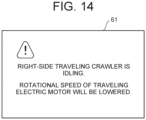
- FIG. 13 is a flowchart illustrating a flow of an operation according to still another example of the overspeed avoidance control of the turning electric motor M2.
- S1 to S3 are the same as in FIG. 8 . If the system controller 56 determines at S3 that there is an abnormality, then, as shown in FIG. 14 , the system controller 56 lowers the rotational speed of the traveling electric motor M1 so that the rotational speed of the turning electric motor M2 becomes equal to or smaller than the allowable rotational speed, while causing the display unit 61 to display that an abnormality has occurred (S4-4).
- the operator can recognize the abnormality of the vehicle (the idling of the one traveling crawler 2) on the basis of the display of the display unit 61. Further, by reducing the rotational speed of the traveling electric motor M1, even if the turning electric motor M2 is rotated from the foot, the rotational speed of the turning electric motor M2 can be set to the allowable rotational speed or less. In this way, from the viewpoint of reducing the overspeed of the turning electric motor M2 and damage caused by that, the system controller 56 may execute control so as to reduce the rotational speed of the traveling electric motor M1 after determining that there is an abnormality (see S4-4).
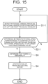
- FIG. 15 is a flowchart illustrating a flow of an operation according to still another example of the overspeed avoidance control of the turning electric motor M2.
- the left-side sensor 71SL and the right-side sensor 71SR detect the rotational speeds (traveling rotational speeds R1a and R1b) of the rotating shafts (drive shafts 6a and 6b) of the respective drive wheels of the left and right traveling crawlers 2 (S1-1).
- the system controller 56 determines whether or not the difference between the rotational speed RC (1/min) of the turning electric motor M2 corresponding to the command value output to the inverter 52 and the traveling rotational speed R1a (1/min) detected at S1-1 is equal to or larger than a predetermined value R0 (1/min) (S2-1). In addition, at S2-1, it is determined whether or not the difference between the rotational speed RC and the traveling rotational speed R1b (1/min) detected at S1-1 is equal to or larger than the predetermined value R0. If the difference between the rotational speed RC corresponding to the command value and the traveling rotational speed R1a (or R1b) is less than the predetermined value R0 (No at S2-1), the processing returns to S1 and repeats the operation at S1 and after.
- the system controller 56 determines that there is an abnormality (S3), and then outputs a command value to the inverter 52 and stops the rotation of the traveling electric motor M1 (S4).
- the command value for controlling the rotation of the turning electric motor M2 corresponds to the rotational speed zero.
- the difference between the rotational speed RC corresponding to the aforementioned command value and the traveling rotational speed R1a (or R1b) is equal to or larger than the predetermined value R0, it can be determined that one of the left and right traveling crawlers 2 idles and rotates at a high speed, whereby the turning electric motor M2 is turned from the foot and brought into overspeed.
- the electric crawler 1 may include the left-side sensor 71SL and the right-side sensor 71SR.
- the system controller 56 may determine that there is an abnormality when the difference between the rotational speed RC of the turning electric motor M2 corresponding to the command value and the traveling rotational speed R1a (or R1b) is equal to or larger than the predetermined value R0 (see S2-1 and S3).
- overspeed avoidance control of the turning electric motor M2 can be combined as appropriate. For example, if the operator does not take any measures within a predetermined time after the issuance of an alarm at S4-1 in FIG. 9 , the following control may be further executed. For example, the rotation of the traveling electric motor M1 may be stopped as at S4 in FIG. 8 . As at S4-2 in FIG. 10 , the rotation of the turning electric motor M2 may be controlled so as to approach the differential lock state.
- the rotational speed of the traveling electric motor M1 may be controlled to be lowered together with the display of the occurrence of the abnormality on the display unit 61.
- the electric crawler 1 is of such a type that the crawler belt 7 is wound around one drive wheel (drive sprocket) and two driven wheels (driven sprockets) in a triangular shape has been described, but the electric crawler 1 may be of such a type that the crawler belt 7 is wound around one drive wheel and one driven wheel aligned in the front-rear direction.
- the electric crawler 1 described in this Embodiment can also be expressed as an electric crawler vehicle described in the following supplements.
- the electric crawler vehicle of Appendix (1) includes
- the electric crawler vehicle of Appendix (2) is configured such that, in the electric controller vehicle described in Appendix (1), a maximum output of the turning electric motor is smaller than a maximum output of the traveling electric motor.
- the electric crawler vehicle of Appendix (3) includes, in the electric crawler vehicle described in Appendix (1) or (2),
- the electric crawler vehicle of Appendix (4) is configured such that, in the electric crawler vehicle described in Appendix (3), after determining that there is the abnormality, the control unit stops rotation of the traveling electric motor.
- the electric crawler vehicle of Appendix (5) is configured such that, in the electric crawler vehicle described in Appendix (3),
- the electric crawler vehicle of Appendix (6) is configured such that, in the electric crawler vehicle described in Appendix (3), after determining that there is the abnormality, the control unit rotates the turning electric motor in a rotational direction approaching a differential lock state.
- the electric crawler vehicle of Appendix (7) is configured such that, in the electric crawler vehicle described in Appendix (3),
- the electric crawler vehicle of Appendix (8) is configured such that, in the electric crawler vehicle described in Appendix (3) or (7), a display unit that displays information is further provided, and after determining that there is the abnormality, the control unit lowers the rotational speed of the traveling electric motor so that the rotational speed of the turning electric motor becomes equal to or smaller than an allowable rotational speed, while causing the display unit to display that an abnormality has occurred.
- the electric crawler vehicle of Appendix (9) further includes, in the electric crawler vehicle described in Appendix (3), a left-side sensor and a right-side sensor for detecting a rotational speed of a rotating shaft of each drive wheel of left and right crawlers, respectively.
- the electric crawler vehicle of Appendix (10) is configured such that, in the electric crawler vehicle described in Appendix (9), the control unit determines that there is an abnormality, when a difference between a rotational speed of the turning electric motor corresponding to the command value and the rotational speed detected by the left-side sensor or the right-side sensor is equal to or larger than a predetermined value.
- the present invention is applicable to a crawler vehicle used as a work machine such as an agricultural machine and a construction machine.
Landscapes
- Engineering & Computer Science (AREA)
- Chemical & Material Sciences (AREA)
- Combustion & Propulsion (AREA)
- Transportation (AREA)
- Mechanical Engineering (AREA)
- Automation & Control Theory (AREA)
- Non-Deflectable Wheels, Steering Of Trailers, Or Other Steering (AREA)
Applications Claiming Priority (1)
| Application Number | Priority Date | Filing Date | Title |
|---|---|---|---|
| JP2023144378A JP2025037443A (ja) | 2023-09-06 | 2023-09-06 | 電動クローラ車両 |
Publications (1)
| Publication Number | Publication Date |
|---|---|
| EP4523939A1 true EP4523939A1 (de) | 2025-03-19 |
Family
ID=92708732
Family Applications (1)
| Application Number | Title | Priority Date | Filing Date |
|---|---|---|---|
| EP24198559.7A Pending EP4523939A1 (de) | 2023-09-06 | 2024-09-05 | Elektrisches raupenfahrzeug |
Country Status (5)
| Country | Link |
|---|---|
| US (1) | US20250074518A1 (de) |
| EP (1) | EP4523939A1 (de) |
| JP (1) | JP2025037443A (de) |
| KR (1) | KR20250036030A (de) |
| CN (1) | CN119568265A (de) |
Citations (6)
| Publication number | Priority date | Publication date | Assignee | Title |
|---|---|---|---|---|
| US4998591A (en) * | 1987-08-24 | 1991-03-12 | Renk Aktiengesellschaft | Electro-mechanical drive system for a full-track vehicle |
| EP1506905A1 (de) * | 2001-04-17 | 2005-02-16 | Qinetiq Limited | Geregeltes Differential |
| JP2009202764A (ja) * | 2008-02-28 | 2009-09-10 | Yanmar Co Ltd | 作業車輌 |
| WO2019051314A1 (en) * | 2017-09-08 | 2019-03-14 | Chu Shaun | DIFFERENTIAL SYSTEM COMPRISING DIFFERENTIAL SPEED-SPEED PLANETARY GEARS GOVERNED BY A VARIABLE SPEED MOTOR AND METHOD OF OPERATION THEREOF |
| JP2020011591A (ja) | 2018-07-18 | 2020-01-23 | 株式会社アイチコーポレーション | 走行車両 |
| CN112805205A (zh) * | 2018-07-03 | 2021-05-14 | 利勃海尔比伯拉赫零部件有限公司 | 履带式车辆 |
-
2023
- 2023-09-06 JP JP2023144378A patent/JP2025037443A/ja active Pending
-
2024
- 2024-08-29 CN CN202411196856.0A patent/CN119568265A/zh active Pending
- 2024-09-04 KR KR1020240120164A patent/KR20250036030A/ko active Pending
- 2024-09-05 EP EP24198559.7A patent/EP4523939A1/de active Pending
- 2024-09-05 US US18/826,080 patent/US20250074518A1/en active Pending
Patent Citations (6)
| Publication number | Priority date | Publication date | Assignee | Title |
|---|---|---|---|---|
| US4998591A (en) * | 1987-08-24 | 1991-03-12 | Renk Aktiengesellschaft | Electro-mechanical drive system for a full-track vehicle |
| EP1506905A1 (de) * | 2001-04-17 | 2005-02-16 | Qinetiq Limited | Geregeltes Differential |
| JP2009202764A (ja) * | 2008-02-28 | 2009-09-10 | Yanmar Co Ltd | 作業車輌 |
| WO2019051314A1 (en) * | 2017-09-08 | 2019-03-14 | Chu Shaun | DIFFERENTIAL SYSTEM COMPRISING DIFFERENTIAL SPEED-SPEED PLANETARY GEARS GOVERNED BY A VARIABLE SPEED MOTOR AND METHOD OF OPERATION THEREOF |
| CN112805205A (zh) * | 2018-07-03 | 2021-05-14 | 利勃海尔比伯拉赫零部件有限公司 | 履带式车辆 |
| JP2020011591A (ja) | 2018-07-18 | 2020-01-23 | 株式会社アイチコーポレーション | 走行車両 |
Also Published As
| Publication number | Publication date |
|---|---|
| US20250074518A1 (en) | 2025-03-06 |
| KR20250036030A (ko) | 2025-03-13 |
| JP2025037443A (ja) | 2025-03-18 |
| CN119568265A (zh) | 2025-03-07 |
Similar Documents
| Publication | Publication Date | Title |
|---|---|---|
| US11433771B2 (en) | Electric travelling vehicle and grass mower | |
| CN102991329B (zh) | 混合动力作业车辆 | |
| US10639983B2 (en) | Work vehicle | |
| US20080230284A1 (en) | Offset drive system for utility vehicles | |
| US20050173162A1 (en) | Electric drive system with differential steering | |
| US5960897A (en) | Auxiliary vehicle driving system | |
| CN1323265A (zh) | 车辆的副机驱动装置 | |
| EP4523939A1 (de) | Elektrisches raupenfahrzeug | |
| US20250074508A1 (en) | Electric crawler vehicle | |
| JP2014131385A (ja) | 高架線走行装置および高架線走行装置用アシスト装置 | |
| JP6156417B2 (ja) | ハイブリッド車両 | |
| GB2511085A (en) | Electric drive system | |
| JP2010071353A (ja) | 歯車式多段変速機 | |
| EP4474191A1 (de) | Verfahren zur steuerung einer achsanordnung | |
| JP5394907B2 (ja) | 走行装置 | |
| JP4607002B2 (ja) | 走行型車両 | |
| JP2010208446A (ja) | 作業機 | |
| US20250196603A1 (en) | Travel drive device of electric work vehicle | |
| US20250282419A1 (en) | Work vehicle | |
| US20250340111A1 (en) | Work Vehicle | |
| JP2004149098A (ja) | 自転車用電動式車輪駆動装置 | |
| JP2000156910A (ja) | ハイブリッド車の制御装置 | |
| KR101817488B1 (ko) | 차량용 조향장치 | |
| JP6201506B2 (ja) | トラクタ | |
| JP2011155848A (ja) | ハイブリッド作業車 |
Legal Events
| Date | Code | Title | Description |
|---|---|---|---|
| PUAI | Public reference made under article 153(3) epc to a published international application that has entered the european phase |
Free format text: ORIGINAL CODE: 0009012 |
|
| STAA | Information on the status of an ep patent application or granted ep patent |
Free format text: STATUS: THE APPLICATION HAS BEEN PUBLISHED |
|
| AK | Designated contracting states |
Kind code of ref document: A1 Designated state(s): AL AT BE BG CH CY CZ DE DK EE ES FI FR GB GR HR HU IE IS IT LI LT LU LV MC ME MK MT NL NO PL PT RO RS SE SI SK SM TR |
|
| STAA | Information on the status of an ep patent application or granted ep patent |
Free format text: STATUS: REQUEST FOR EXAMINATION WAS MADE |
|
| 17P | Request for examination filed |
Effective date: 20250826 |