EP4523869A1 - Querschneidevorrichtung, beutelherstellungsmaschine und querschneideverfahren - Google Patents
Querschneidevorrichtung, beutelherstellungsmaschine und querschneideverfahren Download PDFInfo
- Publication number
- EP4523869A1 EP4523869A1 EP23803237.9A EP23803237A EP4523869A1 EP 4523869 A1 EP4523869 A1 EP 4523869A1 EP 23803237 A EP23803237 A EP 23803237A EP 4523869 A1 EP4523869 A1 EP 4523869A1
- Authority
- EP
- European Patent Office
- Prior art keywords
- web
- upper blade
- blade
- feed
- shear
- Prior art date
- Legal status (The legal status is an assumption and is not a legal conclusion. Google has not performed a legal analysis and makes no representation as to the accuracy of the status listed.)
- Pending
Links
Images


Classifications
-
- B—PERFORMING OPERATIONS; TRANSPORTING
- B26—HAND CUTTING TOOLS; CUTTING; SEVERING
- B26D—CUTTING; DETAILS COMMON TO MACHINES FOR PERFORATING, PUNCHING, CUTTING-OUT, STAMPING-OUT OR SEVERING
- B26D7/00—Details of apparatus for cutting, cutting-out, stamping-out, punching, perforating, or severing by means other than cutting
- B26D7/18—Means for removing cut-out material or waste
- B26D7/1818—Means for removing cut-out material or waste by pushing out
-
- B—PERFORMING OPERATIONS; TRANSPORTING
- B31—MAKING ARTICLES OF PAPER, CARDBOARD OR MATERIAL WORKED IN A MANNER ANALOGOUS TO PAPER; WORKING PAPER, CARDBOARD OR MATERIAL WORKED IN A MANNER ANALOGOUS TO PAPER
- B31B—MAKING CONTAINERS OF PAPER, CARDBOARD OR MATERIAL WORKED IN A MANNER ANALOGOUS TO PAPER
- B31B70/00—Making flexible containers, e.g. envelopes or bags
- B31B70/14—Cutting, e.g. perforating, punching, slitting or trimming
- B31B70/16—Cutting webs
-
- B—PERFORMING OPERATIONS; TRANSPORTING
- B31—MAKING ARTICLES OF PAPER, CARDBOARD OR MATERIAL WORKED IN A MANNER ANALOGOUS TO PAPER; WORKING PAPER, CARDBOARD OR MATERIAL WORKED IN A MANNER ANALOGOUS TO PAPER
- B31B—MAKING CONTAINERS OF PAPER, CARDBOARD OR MATERIAL WORKED IN A MANNER ANALOGOUS TO PAPER
- B31B70/00—Making flexible containers, e.g. envelopes or bags
- B31B70/02—Feeding or positioning sheets, blanks or webs
- B31B70/10—Feeding or positioning webs
-
- B—PERFORMING OPERATIONS; TRANSPORTING
- B31—MAKING ARTICLES OF PAPER, CARDBOARD OR MATERIAL WORKED IN A MANNER ANALOGOUS TO PAPER; WORKING PAPER, CARDBOARD OR MATERIAL WORKED IN A MANNER ANALOGOUS TO PAPER
- B31B—MAKING CONTAINERS OF PAPER, CARDBOARD OR MATERIAL WORKED IN A MANNER ANALOGOUS TO PAPER
- B31B70/00—Making flexible containers, e.g. envelopes or bags
- B31B70/60—Uniting opposed surfaces or edges; Taping
- B31B70/64—Uniting opposed surfaces or edges; Taping by applying heat or pressure
- B31B70/644—Making seals parallel to the direction of movement, i.e. longitudinal sealing
-
- B—PERFORMING OPERATIONS; TRANSPORTING
- B31—MAKING ARTICLES OF PAPER, CARDBOARD OR MATERIAL WORKED IN A MANNER ANALOGOUS TO PAPER; WORKING PAPER, CARDBOARD OR MATERIAL WORKED IN A MANNER ANALOGOUS TO PAPER
- B31B—MAKING CONTAINERS OF PAPER, CARDBOARD OR MATERIAL WORKED IN A MANNER ANALOGOUS TO PAPER
- B31B70/00—Making flexible containers, e.g. envelopes or bags
- B31B70/60—Uniting opposed surfaces or edges; Taping
- B31B70/64—Uniting opposed surfaces or edges; Taping by applying heat or pressure
- B31B70/645—Making seals transversally to the direction of movement
-
- B—PERFORMING OPERATIONS; TRANSPORTING
- B26—HAND CUTTING TOOLS; CUTTING; SEVERING
- B26D—CUTTING; DETAILS COMMON TO MACHINES FOR PERFORATING, PUNCHING, CUTTING-OUT, STAMPING-OUT OR SEVERING
- B26D1/00—Cutting through work characterised by the nature or movement of the cutting member or particular materials not otherwise provided for; Apparatus or machines therefor; Cutting members therefor
- B26D1/01—Cutting through work characterised by the nature or movement of the cutting member or particular materials not otherwise provided for; Apparatus or machines therefor; Cutting members therefor involving a cutting member which does not travel with the work
- B26D1/02—Cutting through work characterised by the nature or movement of the cutting member or particular materials not otherwise provided for; Apparatus or machines therefor; Cutting members therefor involving a cutting member which does not travel with the work having a stationary cutting member
- B26D1/025—Cutting through work characterised by the nature or movement of the cutting member or particular materials not otherwise provided for; Apparatus or machines therefor; Cutting members therefor involving a cutting member which does not travel with the work having a stationary cutting member for thin material, e.g. for sheets, strips or the like
-
- B—PERFORMING OPERATIONS; TRANSPORTING
- B26—HAND CUTTING TOOLS; CUTTING; SEVERING
- B26D—CUTTING; DETAILS COMMON TO MACHINES FOR PERFORATING, PUNCHING, CUTTING-OUT, STAMPING-OUT OR SEVERING
- B26D1/00—Cutting through work characterised by the nature or movement of the cutting member or particular materials not otherwise provided for; Apparatus or machines therefor; Cutting members therefor
- B26D1/01—Cutting through work characterised by the nature or movement of the cutting member or particular materials not otherwise provided for; Apparatus or machines therefor; Cutting members therefor involving a cutting member which does not travel with the work
- B26D1/04—Cutting through work characterised by the nature or movement of the cutting member or particular materials not otherwise provided for; Apparatus or machines therefor; Cutting members therefor involving a cutting member which does not travel with the work having a linearly-movable cutting member
- B26D1/06—Cutting through work characterised by the nature or movement of the cutting member or particular materials not otherwise provided for; Apparatus or machines therefor; Cutting members therefor involving a cutting member which does not travel with the work having a linearly-movable cutting member wherein the cutting member reciprocates
- B26D1/065—Cutting through work characterised by the nature or movement of the cutting member or particular materials not otherwise provided for; Apparatus or machines therefor; Cutting members therefor involving a cutting member which does not travel with the work having a linearly-movable cutting member wherein the cutting member reciprocates for thin material, e.g. for sheets, strips or the like
-
- B—PERFORMING OPERATIONS; TRANSPORTING
- B26—HAND CUTTING TOOLS; CUTTING; SEVERING
- B26D—CUTTING; DETAILS COMMON TO MACHINES FOR PERFORATING, PUNCHING, CUTTING-OUT, STAMPING-OUT OR SEVERING
- B26D1/00—Cutting through work characterised by the nature or movement of the cutting member or particular materials not otherwise provided for; Apparatus or machines therefor; Cutting members therefor
- B26D1/0006—Cutting members therefor
- B26D2001/0066—Cutting members therefor having shearing means, e.g. shearing blades, abutting blades
-
- B—PERFORMING OPERATIONS; TRANSPORTING
- B26—HAND CUTTING TOOLS; CUTTING; SEVERING
- B26D—CUTTING; DETAILS COMMON TO MACHINES FOR PERFORATING, PUNCHING, CUTTING-OUT, STAMPING-OUT OR SEVERING
- B26D5/00—Arrangements for operating and controlling machines or devices for cutting, cutting-out, stamping-out, punching, perforating, or severing by means other than cutting
- B26D5/02—Means for moving the cutting member into its operative position for cutting
- B26D5/06—Means for moving the cutting member into its operative position for cutting by electrical means
-
- B—PERFORMING OPERATIONS; TRANSPORTING
- B26—HAND CUTTING TOOLS; CUTTING; SEVERING
- B26D—CUTTING; DETAILS COMMON TO MACHINES FOR PERFORATING, PUNCHING, CUTTING-OUT, STAMPING-OUT OR SEVERING
- B26D5/00—Arrangements for operating and controlling machines or devices for cutting, cutting-out, stamping-out, punching, perforating, or severing by means other than cutting
- B26D5/20—Arrangements for operating and controlling machines or devices for cutting, cutting-out, stamping-out, punching, perforating, or severing by means other than cutting with interrelated action between the cutting member and work feed
- B26D5/22—Arrangements for operating and controlling machines or devices for cutting, cutting-out, stamping-out, punching, perforating, or severing by means other than cutting with interrelated action between the cutting member and work feed having the cutting member and work feed mechanically connected
-
- B—PERFORMING OPERATIONS; TRANSPORTING
- B26—HAND CUTTING TOOLS; CUTTING; SEVERING
- B26D—CUTTING; DETAILS COMMON TO MACHINES FOR PERFORATING, PUNCHING, CUTTING-OUT, STAMPING-OUT OR SEVERING
- B26D7/00—Details of apparatus for cutting, cutting-out, stamping-out, punching, perforating, or severing by means other than cutting
- B26D7/18—Means for removing cut-out material or waste
- B26D7/1845—Means for removing cut-out material or waste by non mechanical means
- B26D7/1854—Means for removing cut-out material or waste by non mechanical means by air under pressure
-
- B—PERFORMING OPERATIONS; TRANSPORTING
- B26—HAND CUTTING TOOLS; CUTTING; SEVERING
- B26D—CUTTING; DETAILS COMMON TO MACHINES FOR PERFORATING, PUNCHING, CUTTING-OUT, STAMPING-OUT OR SEVERING
- B26D7/00—Details of apparatus for cutting, cutting-out, stamping-out, punching, perforating, or severing by means other than cutting
- B26D7/18—Means for removing cut-out material or waste
- B26D7/1845—Means for removing cut-out material or waste by non mechanical means
- B26D7/1863—Means for removing cut-out material or waste by non mechanical means by suction
-
- B—PERFORMING OPERATIONS; TRANSPORTING
- B26—HAND CUTTING TOOLS; CUTTING; SEVERING
- B26D—CUTTING; DETAILS COMMON TO MACHINES FOR PERFORATING, PUNCHING, CUTTING-OUT, STAMPING-OUT OR SEVERING
- B26D9/00—Cutting apparatus combined with punching or perforating apparatus or with dissimilar cutting apparatus
-
- B—PERFORMING OPERATIONS; TRANSPORTING
- B26—HAND CUTTING TOOLS; CUTTING; SEVERING
- B26F—PERFORATING; PUNCHING; CUTTING-OUT; STAMPING-OUT; SEVERING BY MEANS OTHER THAN CUTTING
- B26F1/00—Perforating; Punching; Cutting-out; Stamping-out; Apparatus therefor
- B26F1/02—Perforating by punching, e.g. with relatively-reciprocating punch and bed
- B26F1/12—Perforating by punching, e.g. with relatively-reciprocating punch and bed to notch margins of work
-
- B—PERFORMING OPERATIONS; TRANSPORTING
- B26—HAND CUTTING TOOLS; CUTTING; SEVERING
- B26F—PERFORATING; PUNCHING; CUTTING-OUT; STAMPING-OUT; SEVERING BY MEANS OTHER THAN CUTTING
- B26F1/00—Perforating; Punching; Cutting-out; Stamping-out; Apparatus therefor
- B26F1/02—Perforating by punching, e.g. with relatively-reciprocating punch and bed
- B26F1/14—Punching tools; Punching dies
-
- B—PERFORMING OPERATIONS; TRANSPORTING
- B26—HAND CUTTING TOOLS; CUTTING; SEVERING
- B26F—PERFORATING; PUNCHING; CUTTING-OUT; STAMPING-OUT; SEVERING BY MEANS OTHER THAN CUTTING
- B26F2210/00—Perforating, punching, cutting-out, stamping-out, severing by means other than cutting of specific products
- B26F2210/11—Perforating, punching, cutting-out, stamping-out, severing by means other than cutting of specific products of plastic containers before compressing
-
- B—PERFORMING OPERATIONS; TRANSPORTING
- B31—MAKING ARTICLES OF PAPER, CARDBOARD OR MATERIAL WORKED IN A MANNER ANALOGOUS TO PAPER; WORKING PAPER, CARDBOARD OR MATERIAL WORKED IN A MANNER ANALOGOUS TO PAPER
- B31B—MAKING CONTAINERS OF PAPER, CARDBOARD OR MATERIAL WORKED IN A MANNER ANALOGOUS TO PAPER
- B31B2155/00—Flexible containers made from webs
- B31B2155/001—Flexible containers made from webs by folding webs longitudinally
- B31B2155/0014—Flexible containers made from webs by folding webs longitudinally having their openings facing transversally to the direction of movement
-
- B—PERFORMING OPERATIONS; TRANSPORTING
- B31—MAKING ARTICLES OF PAPER, CARDBOARD OR MATERIAL WORKED IN A MANNER ANALOGOUS TO PAPER; WORKING PAPER, CARDBOARD OR MATERIAL WORKED IN A MANNER ANALOGOUS TO PAPER
- B31B—MAKING CONTAINERS OF PAPER, CARDBOARD OR MATERIAL WORKED IN A MANNER ANALOGOUS TO PAPER
- B31B2155/00—Flexible containers made from webs
- B31B2155/002—Flexible containers made from webs by joining superimposed webs, e.g. with separate bottom webs
-
- B—PERFORMING OPERATIONS; TRANSPORTING
- B31—MAKING ARTICLES OF PAPER, CARDBOARD OR MATERIAL WORKED IN A MANNER ANALOGOUS TO PAPER; WORKING PAPER, CARDBOARD OR MATERIAL WORKED IN A MANNER ANALOGOUS TO PAPER
- B31B—MAKING CONTAINERS OF PAPER, CARDBOARD OR MATERIAL WORKED IN A MANNER ANALOGOUS TO PAPER
- B31B70/00—Making flexible containers, e.g. envelopes or bags
- B31B70/006—Controlling; Regulating; Measuring; Safety measures
-
- B—PERFORMING OPERATIONS; TRANSPORTING
- B31—MAKING ARTICLES OF PAPER, CARDBOARD OR MATERIAL WORKED IN A MANNER ANALOGOUS TO PAPER; WORKING PAPER, CARDBOARD OR MATERIAL WORKED IN A MANNER ANALOGOUS TO PAPER
- B31B—MAKING CONTAINERS OF PAPER, CARDBOARD OR MATERIAL WORKED IN A MANNER ANALOGOUS TO PAPER
- B31B70/00—Making flexible containers, e.g. envelopes or bags
- B31B70/60—Uniting opposed surfaces or edges; Taping
- B31B70/64—Uniting opposed surfaces or edges; Taping by applying heat or pressure
Definitions
- This application relates to a cross cut device for shearing a web and a bag making apparatus including said cross cut device. This application also relates to a cross cut method for shearing a web used for bag making.
- a bag making apparatus for example, includes an intermittent feed device that intermittently feeds a web in the longitudinal direction of the web, a processing device that processes the web during a pause phase of an intermittent feed cycle, and a cross cut device that cuts the processed web in the width direction of the web to shape a bag during a pause phase of an intermittent feed cycle.
- the processing device is a heat seal device that heat-seals the web in the width direction and/or longitudinal direction of the web and/or a punching machine that punches the web such that the shaped bag has corner cut parts.
- the corner cut part for example, has a rounded shape, which can prevent hurt.
- the corner cut part can also improve the appearance of the bag.
- the cross cut device is located downstream of the processing device.
- the cross cut device typically shears the web using a cutter pair including an upper blade and a lower blade.
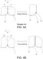
- Cross-cutting may involve single shearing only or twice shearing.
- a protrusion such as the one illustrated by the reference sign 170a in FIG. 13B in Patent Document 1 ( WO2019/123875A1 )
- This may degrade the appearance of the bag, and may also be a cause of hurt.
- the latter case can prevent the generation of such a protrusion (see, for example, Fig. 11 in Patent Document 2 ( WO2019/163496A1 )). Specifically, the latter case shears the web using the cutter pair (the first time), moves the cutter pair upstream, shears the web again using the cutter pair (the second time), and then moves again the cutter pair downstream back to its initial position.
- Patent Document 1 WO2019/123875A1 .
- Patent Document 2 WO2019/163496A1
- An object of this application is to ensure that a waste generated by cross-cutting which involves twice shearing is separated from a web.
- a cross cut device for use in a bag making apparatus and for shearing a web twice during a pause phase of an intermittent feed cycle.
- the cross cut device includes: a cutter pair including an upper blade and a lower blade; a feed device for intermittently feeding a web in a longitudinal direction of the web; a vertical movement device for vertically reciprocating the upper blade with respect to the lower blade to shear the web; and a horizontal movement device for horizontally moving the cutter pair between a first position for first shearing and a second position for second shearing, the second position being spaced upstream of the first position.
- the horizontal movement device is configured, during the reciprocation of the upper blade for the second shearing, to start to move the cutter pair from the second position to the first position subsequent to the upper blade reaching a lowermost height and prior to the upper blade exceeding a shear height.
- the feed device is configured to start to feed the web subsequent to the cutter pair starting to move from the second position to the first position.
- the feed device may be configured to, during the reciprocation of the upper blade for the second shearing, start to feed the web prior to the upper blade exceeding the shear height and pass the web through a space between the upper blade and the lower blade subsequent to the upper blade exceeding the shear height.
- the feed device may be configured to, during the reciprocation of the upper blade for the second shearing, start to feed the web subsequent to the upper blade exceeding the shear height and prior to the upper blade reaching an uppermost height.
- a bag making apparatus for successively making bags from at least one web, including the cross cut device described above.
- the bag making apparatus may further include a punching machine disposed upstream of the cross cut device to punch the web during every intermittent feed cycle.
- the punching machine may include: a first punching blade for punching a hole or cutout for corner cut parts in the web; and a second punching blade for punching a hole for notches in the web at a position spaced in a width direction of the web away from the hole or cutout for the corner cut parts.
- the cross cut device may be configured to shear the web in the width direction of the web across the hole or cutout for the corner cut parts and the hole for the notches to shape the bag having the notches and the corner cut parts.
- a cross cut method for shearing a web using a cutter pair including an upper blade and a lower blade to shape a bag includes: (a) pausing feeding the web; (b) reciprocating the upper blade vertically with respect to the lower blade to shear the web in a width direction of the web at a first position during the step (a); (c) moving the cutter pair from the first position to a second position spaced upstream of the first position, following the step (b) and during the step (a); (d) reciprocating the upper blade again vertically with respect to the lower blade to shear the web at the second position, following to the step (c); (e) starting to move the cutter pair from the second position to the first position after the upper blade reaches a lowermost height in the step (d) and before the upper blade exceeds a shear height in the step (d); and (f) starting to feed the web in a longitudinal direction of the web after the step (e).
- the step (f) may include: starting to feed the web before the upper blade exceeds the shear height in the step (d); and passing the web through a space between the upper blade and the lower blade after the upper blade exceeds the shear height in the step (d).
- the step (f) may include starting to feed the web after the upper blade exceeds the shear height in the step (d) and before the upper blade reaches an uppermost height in the step (d).
- the web may include a sealant layer.
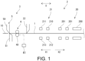
- Fig. 1 illustrates a downstream section of an example bag making apparatus.
- a web 1 is unrolled from the original roll (not illustrated) located in the upstream zone of the bag making apparatus.
- the web 1 is intermittently fed in its longitudinal direction in the downstream zone of the bag making apparatus. Therefore, the web 1 is repeatedly fed and paused.
- the feed direction is designated by the reference sign X1.
- two webs 1 are intermittently fed in a state in which they are superposed on each other.
- one web 1 in a state of being folded in half may be intermittently fed.
- the web(s) 1 is, in the embodiment, a laminated film in which one side surface thereof is constituted by a base and the other side surface thereof is constituted by a sealant.
- the web 1 may include a base made of paper and resin applied at least partially to the base.
- the web 1 may be made of mono-material.
- the bag making apparatus includes a cross cut device 3 for shearing the webs 1 in the width direction Y ( Fig. 2 ) of the webs 1 during every intermittent feed cycle to shape bags 10, and a processing device 2 disposed upstream of the cross cut device 3 to process the webs 1 during every intermittent feed cycle.
- the processing device 2 includes a heat seal device 20, a punching machine 21, and a slitter 22.
- the heat seal device 20 heat-seals the webs 1 during every intermittent feed cycle.
- the heat seal device 20 includes longitudinal heaters 200 that heat-seal the webs 1 in the longitudinal direction X of the webs 1 to form longitudinal sealed sections 11 ( Fig.2 ) and cross heaters 201 that heat-seal the webs 1 in the width direction Y to form cross sealed sections 12 ( Fig. 2 ).
- These heaters 200 and 201 include, for example, heat seal bars.
- the punching machine 21 punches the webs 1 during every intermittent feed cycle.
- the punching machine 21 includes at least one punching blade 210 for punching a hole 13 and/or a notch 14 for corner cut parts 16 in the webs 1 as illustrated in Fig. 2 , and at least one punching blade 211 for punching a hole 15 for notches 17 in the webs 1 as illustrated in Fig. 2 .
- Receiving blades 212 and 213 are provided for these punching blades 210 and 211, respectively.
- each of the holes 15 for the notches 17 is formed in the webs 1 at a distance in the width direction Y of the webs 1 from the hole 13 and notches 14 for the corner cut parts 16.
- the wastes generated by punching are eliminated by means of suction or other means (not illustrated).
- the cutting edge of the punching blade 210 has a loop shape like with four substantially arc-shaped corner cut parts 16 connected, as illustrated in Fig. 3A .
- the cutting edge of the punching blade 211 has a substantially rhombic shape like with substantially two notches 17 connected, as illustrated in Fig 3B .
- the slitter 22 is positioned, for example, in the center of the webs 1 in the width direction Y. As the webs 1 are fed, the webs 1 are slit in its longitudinal direction X by the slitter 22.
- the cross cut device 3 shears the webs 1 in the width direction Y during every intermittent feed cycle to shape bags 10 from the webs 1.
- the embodiment provides the so-called two-line bag making. That is, as illustrated in Fig. 2 , two bags 10 are shaped every cycle of cross-cutting.
- the cross cut device 3 shears the webs 1 twice during a pause phase of an intermittent feed cycle, as described below. As illustrated in Fig. 2 , the portions cut-off from the webs 1 at the first shearing become the bags 10. The panel parts of the bag 10 are formed from the webs 1. The portions cut-off from the webs 1 at the second shearing are a waste 18.
- the cross cut device 3 shears the webs 1 in the width direction Y across the holes 13 and 15, and the notches 14.
- the bag 10 has the corner cut parts 16 and the notches 17.
- the arc-shaped corner cut parts 16 are located at the four corners of the rectangular bag 10 and serve to prevent hurt.
- the notches 17 are located on the opposite side edges of the bag 10, which facilitate opening the bag 10.
- the waste 18 includes small wastes 180.
- the cross cut device 3 includes a feed device 4 for intermittently feeding the webs 1 in the direction X1.
- the feed device 4 includes two feed rollers 40 and an actuator 41 (e.g., a motor). At least one of the feed rollers 40 is operably connected to the actuator 41.
- the feed rollers 40 which sandwich the webs 1 therebetween being intermittently rotated by the actuator 41 causes the webs 1 to be intermittently fed.
- the cross cut device 3 includes a cutter pair 5 located downstream of the feed rollers 40.
- the cutter pair 5 includes an upper blade 50 and a lower blade 51 for shearing the webs 1.
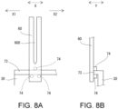
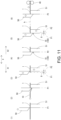
- the cross cut device 3 includes a vertical movement device 6 ( Fig. 5B , Fig. 6B ) for moving the upper blade 50 vertically with respect to the lower blade 51 as illustrated in Fig. 11 , and a horizontal movement device 7 ( Fig. 5B ) for moving the cutter pair 5 upstream (in the direction X2) and downstream (in the direction X1).
- a crank mechanism may be employed as the vertical movement device 6.
- slide frames 60 are located on the opposite sides of the upper blade 50.
- each of the slide frames 60 has a guide groove 600 extending vertically.
- slide pins 61 are located on the upper and lower parts of the opposite side surfaces of the upper blade 50. The slide pins 61 are received in the guide groove 600, allowing them to slide along the guide groove 600. This allows the upper blade 50 to move vertically along the guide grooves 600.
- the slide pin 61 is biased upstream (in the direction X2) by a biasing member (not illustrated) such as a spring.
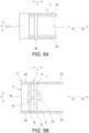
- Fig. 7B illustrates another example cutter pair 5.
- Fig. 7C is an enlarged view of the region T in Fig. 7B
- Fig. 7D is the cross section taken along the line S-S in Fig. 7C .
- the lower blade 51 has a triangular sloping surface 510 at one corner corresponding to the lowest section of the upper blade 50.
- the upper blade 50 moves downward, its blade surface facing upstream rides up on the sloping surface 510, enabling the web(s) 1 to be reliably sheared (cross-cut).
- a slide beam 70 is supported at the opposite ends thereof by the slide frames 60.
- a fixed beam 71 is supported at the opposite ends thereof by support frames 72 which are fixed to the main frames 30.
- the slide beam 70 and the fixed beam 71 extend in the direction Y.
- the slide frames 60 and the slide beam 70 are movable together in the direction X for a small range.
- a rail structure may be employed for this purpose.
- a rail 73 is attached to each of the main frame 30 and extends in the direction X.
- Guide rollers 74 are rotatably supported by the slide frame 60 to sandwich the rail 73.
- the slide beam 70 and the fixed beam 71 are connected to each other via a transmission shaft 75 extending in the direction X.
- a transmission shaft 75 extending in the direction X.
- the transmission shaft 75 is received by the fixed beam 71 to be rotatable and non-displaceable in the direction X.
- a portion of the transmission shaft 75 is configured as a feed screw 750.
- a female thread (not illustrated) is formed on the inner side of the slide beam 70 to be engaged with the feed screw 750.
- the transmission shaft 75 is operatively connected to an actuator 76.
- a motor located on the fixed beam 71 is used as the actuator 76.
- the transmission shaft 75 is connected at one end thereof to a bevel gear 77 which is mounted on the output shaft 760 of the motor 76.
- the transmission shaft 75 being rotated by the actuator 76 causes the slide frames 60 and the slide beam 70 to move in the direction X.
- the transmission shaft 75 being rotated by the actuator 76 causes the cutter pair 5 (upper blade 50 and lower blade 51) to move in the direction X.
- the above-described devices 6 and 7 are merely examples. Any structure may be employed as these devices 6 and 7.
- a motor 76 as the actuator and a bevel gear 77 may be connected via a gear train instead of being directly connected.
- the transmission shaft 75 with the bevel gear 77 may be built into the fixed beam 71.
- the two transmission shafts 75 may be arranged to be spaced from each other in the direction Y to more ensure the horizontal movement of the cutter pair 5.
- the two transmission shafts 75 are operably connected to the actuator 76 via a transmission arrangement including a bevel gear, a gear train, etc., to rotate synchronously.
- the cross cut device 3 includes a control unit 31 (processor, controller, etc.) electrically connected to the actuators 41, 66 and 76.
- the control unit 31 controls the actuators 41, 66 and 76 (and thus the devices 4, 6 and 7) to perform the cross-cutting process.
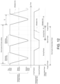
- the cross-cutting process illustrated in Fig. 11 and Fig. 12 are described below.
- the feed device 4 pauses feeding of the web(s) 1.
- the cross cut device 3 shears the web 1 at the first position P1 (the first time).
- the vertical movement device 6 moves the upper blade 50 of the cutter pair 5 (which is at the first position P1) downward from the top dead point (uppermost position) to the bottom dead point (lowermost position), and then moves it from the bottom dead point back to the top dead point.
- the web 1 is sheared in the width direction Y of the web 1 by the upper blade 50 and the lower blade 51 at the first position P1 (see Fig. 11 (1) (2)).
- the bags 10 are shaped by means of this first shearing and fed downstream by a conveyor (not illustrated).
- a waste 18 is inevitably generated by means of the second shearing.
- the width of the waste 18 corresponds to the distance D between the first position P1 and the second position P2.
- small wastes 180 are generated in the embodiment due to the corner-cutting and notching processes.
- the horizontal movement device 7 starts to move the cutter pair 5 downstream (in the direction X1) from the second position P2 back to the first position P1 ( Fig. 11(4)(5) ). Specifically, the horizontal movement device 7 starts to move the cutter pair 5 to the first position P1 after the upper blade 50 reaches the bottom dead point and before it exceeds the shear height h. More specifically, the horizontal movement device 7 starts to move the upper blade 50 from the second position P2 to the first position P1 while the upper blade 50 is staying at the bottom dead point, as illustrated in Fig. 12 .
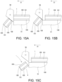
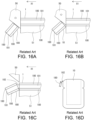
- shear height h is illustrated in Fig. 14A .
- the shear height h is the height at which the upper blade 50 finishes shearing the web 1, as illustrated in Fig. 14A .
- the shear height h of the upper blade 50 is the height at which the upper blade 50 has just blocked the feed path along which the web 1 passes.
- the horizontal movement device 7 then finishes moving (returning) the cutter pair 5 to the first position P1 before or at the time when the upper blade 50 reaches the top dead point. Specifically, the horizontal movement device 7 in the embodiment finishes returning the cutter pair 5 to the first position P1 before the upper blade 50 exceeds the shear height h ( Fig. 11(5) and Fig. 12 ).
- the feed device 4 starts to feed the web 1 in the direction X1 using the feed rollers 40 subsequent to the cutter pair 5 starting to move to the first position P1. Specifically, the feed device 4 in the embodiment starts to feed the web 1 subsequent to the cutter pair 5 starting to move downstream and prior to the upper blade 50 exceeding the shear height h.
- the upper blade 50 is blocking the feed path for the web 1, as illustrated in Fig. 11 (5) (6).
- the feed speed of the web 1 and its timing are controlled such that the tip of the web 1 does not exceed the position of the upstream surface of the upper blade 50 downstream at the time when the upper blade 50 completely releases the feed path for the web 1 by moving upward to the height illustrated in Fig. 14B .
- a space through which the web 1 can pass is secured between the upper blade 50 and the lower blade 51 before the tip of the web 1 reaches the position of the upstream surface of the upper blade 50.
- feedable lower limit height The height of the upper blade 50 indicated in Fig. 14B and Fig. 14C is hereinafter referred to as "feedable lower limit height".
- the feed device 4 finishes feeding the web 1 by the predetermined pitch and pauses the web 1 again. Thereafter, the above steps are repeated as one cycle of cross-cutting.
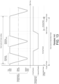
- Fig. 13 illustrates a timing chart according to a comparative example.
- the embodiment in Fig. 12 starts to move the cutter pair 5 downstream from the second position P2 during a period of time from the time at which the upper blade 50 reaches the bottom dead point to the time at which the upper blade 50 reaches the top dead point.
- this timing of the start of the downstream movement of the cutter pair 5 is earlier than that in the comparative example where the cutter pair starts to move from the second position after the upper blade reaches the top dead point.
- the return of the upper blade 50 to the first position P1 is also completed by the time the upper blade 50 reaches the top dead point, which is, of course, earlier than that in the comparative example.
- the embodiment in Fig. 12 starts to feed the web 1 during a period of time from the time at which the cutter pair 5 starts to move to the first position P1 to the time at which the upper blade 50 reaches the top dead point.
- This timing of the start of feeding the web 1 is earlier than that in the comparative example where the web 1 starts to be fed subsequent to the upper blade reaching the top dead point and the cutter pair reaching the first position.
- the embodiment shortens one cycle of cross-cutting by S ( Fig. 12 ) compared to that in the comparative example and also shortens one cycle of intermittent feed. This leads to faster bag making.
- the horizontal movement device 7 may start to move the cutter pair 5 from the second position P2 to the first position P1 immediately upon the upper blade 50 reaching the bottom dead point, and finish moving it back to the first position P1 at once.
- the feed device 4 may then start to feed the web 1.
- the feed device 4 may start to feed the web 1 after the upper blade 50 exceeds the shear height h and before the upper blade 50 reaches the top dead point.
- the feed device 4 may start to feed the web 1 after the upper blade 50 exceeds the feedable lower limit height in Fig. 14B and Fig. 14C .
- the control of the timing and speed of feeding the web 1 is easier because a space through which the web 1 can pass is already secured between the upper blade 50 and the lower blade 51 at the start of feeding the web 1.
- the embodiment has the following advantages regarding the removal of the waste 18, especially the small wastes 180, due to the above configuration.
- the heat seal device 20 in the embodiment heat-seals two webs 1 or a web 1 folded in half to each other by using melting of the sealant layer(s).
- the cross cut device 3 then cross-cuts the web 1 at a position within the cross sealed section 12 ( Fig. 2 ).
- the sealant layer 101 is interposed between the base layers 100 in the web(s) 1 and the small waste(s) 180.
- the horizontal movement device 7 has started to move the upper blade 50 and the lower blade 51 downstream, as described above ( Fig. 15B ). This causes the small waste 180 to be moved away from the tip of the web 1 in the direction X1, which prevents the small waste 180 and the web 1 from being fused via the sealant.
- a suction device (not illustrated) is disposed under the upper blade 51.
- the suction device When the upper blade 50 returns to move upward, the suction device generates a downward airflow by suction to blow the small waste 180 away from the upper blade 50 using this airflow.
- the embodiment can prevent the small wastes 180 from sticking to the webs 1 and thus to the bags 10. Therefore, the embodiment can prevent the small wastes 180 from being mixed as foreign objects during the subsequent filling process.
- cross cut device and method in the present application are also applicable to bag making apparatuses and bag making methods which do not involve notch-forming process and therefore produce not the small wastes 180 but a single elongated waste per cross-cutting.
- a surface treatment for reducing friction such as a Teflon (registered trademark) treatment, may be applied to the surface of the upper blade 50 to more ensure the separation of the small wastes 180 from the upper blade 50.
- the tip of the web 1 will touch the upstream surface of the upper blade 50. If the web 1 starts to be fed after the upper blade 50 has exceeded the feedable lower limit height, the small wastes 180 can be more reliably prevented from sticking to the web 1.
Landscapes
- Life Sciences & Earth Sciences (AREA)
- Forests & Forestry (AREA)
- Engineering & Computer Science (AREA)
- Mechanical Engineering (AREA)
- Making Paper Articles (AREA)
Applications Claiming Priority (2)
| Application Number | Priority Date | Filing Date | Title |
|---|---|---|---|
| JP2022077431 | 2022-05-10 | ||
| PCT/JP2023/010123 WO2023218754A1 (ja) | 2022-05-10 | 2023-03-15 | クロスカット装置、製袋機、および、クロスカット方法 |
Publications (2)
| Publication Number | Publication Date |
|---|---|
| EP4523869A1 true EP4523869A1 (de) | 2025-03-19 |
| EP4523869A4 EP4523869A4 (de) | 2025-09-10 |
Family
ID=88729992
Family Applications (1)
| Application Number | Title | Priority Date | Filing Date |
|---|---|---|---|
| EP23803237.9A Pending EP4523869A4 (de) | 2022-05-10 | 2023-03-15 | Querschneidevorrichtung, beutelherstellungsmaschine und querschneideverfahren |
Country Status (5)
| Country | Link |
|---|---|
| US (1) | US20250289201A1 (de) |
| EP (1) | EP4523869A4 (de) |
| JP (1) | JP7517666B2 (de) |
| CN (1) | CN119136971A (de) |
| WO (1) | WO2023218754A1 (de) |
Family Cites Families (12)
| Publication number | Priority date | Publication date | Assignee | Title |
|---|---|---|---|---|
| US2640539A (en) * | 1949-07-26 | 1953-06-02 | Powers Samas Account Mach Ltd | Apparatus for cutting lengths from a web of paper, cardboard or similar material |
| JP2805515B2 (ja) * | 1989-12-27 | 1998-09-30 | トタニ技研工業株式会社 | プラスチック袋製造装置 |
| JP4121638B2 (ja) * | 1998-10-30 | 2008-07-23 | 大日本印刷株式会社 | 安全ノッチ付き袋の製造方法 |
| JP2003094536A (ja) * | 2001-09-26 | 2003-04-03 | Toyo Kikai Seisakusho:Kk | 四方シール型包装体とその製造装置 |
| JP2007331030A (ja) * | 2006-06-12 | 2007-12-27 | Matsushita Electric Ind Co Ltd | 半導体回路基板の切断方法および切断装置 |
| JP2008023666A (ja) * | 2006-07-21 | 2008-02-07 | Dainippon Printing Co Ltd | 製袋ユニット |
| JP5647384B2 (ja) * | 2007-10-12 | 2014-12-24 | 出光ユニテック株式会社 | 包装袋のカット装置、その方法および製造装置 |
| JP5784872B2 (ja) * | 2009-09-11 | 2015-09-24 | 凸版印刷株式会社 | 製袋インラインカッティング方法及びその装置 |
| WO2019123875A1 (ja) | 2017-12-19 | 2019-06-27 | トタニ技研工業株式会社 | プラスチック袋の製造方法、および、プラスチック袋 |
| WO2019163496A1 (ja) | 2018-02-22 | 2019-08-29 | トタニ技研工業株式会社 | 製袋機、および、プラスチック袋の製造方法 |
| JP6804771B2 (ja) * | 2018-07-30 | 2020-12-23 | トタニ技研工業株式会社 | 製袋機 |
| JP7234833B2 (ja) * | 2019-07-04 | 2023-03-08 | 東洋製罐株式会社 | 製袋装置 |
-
2023
- 2023-03-15 CN CN202380038318.6A patent/CN119136971A/zh active Pending
- 2023-03-15 US US18/862,952 patent/US20250289201A1/en active Pending
- 2023-03-15 WO PCT/JP2023/010123 patent/WO2023218754A1/ja not_active Ceased
- 2023-03-15 JP JP2023550680A patent/JP7517666B2/ja active Active
- 2023-03-15 EP EP23803237.9A patent/EP4523869A4/de active Pending
Also Published As
| Publication number | Publication date |
|---|---|
| CN119136971A (zh) | 2024-12-13 |
| US20250289201A1 (en) | 2025-09-18 |
| WO2023218754A1 (ja) | 2023-11-16 |
| JP7517666B2 (ja) | 2024-07-17 |
| EP4523869A4 (de) | 2025-09-10 |
| JPWO2023218754A1 (de) | 2023-11-16 |
Similar Documents
| Publication | Publication Date | Title |
|---|---|---|
| DE102011115881B4 (de) | Tiefziehverpackungsmaschine mit einseitiger Folienvorschubeinrichtung | |
| JP4829356B2 (ja) | 製袋機 | |
| EP0516487A1 (de) | Längsschweissvorrichtung für Verpackungsmaschine | |
| EP3756875B1 (de) | Beutelherstellungsmaschine und verfahren zur herstellung eines kunststoffbeutels | |
| EP3974168A1 (de) | Beutelherstellungsverfahren und beutelherstellungsvorrichtung | |
| EP1598276A1 (de) | Verpackungsmaschine und Verfahren zum Schneiden von Packungen | |
| EP4523869A1 (de) | Querschneidevorrichtung, beutelherstellungsmaschine und querschneideverfahren | |
| US2636423A (en) | Machine for making partitions | |
| EP3319881B1 (de) | Verpackungsmaschine mit reststreifenentsorgung | |
| DE19820408C2 (de) | Vorrichtung zum Ausstanzen von Behältern aus einer Folienbahn | |
| CN112810176A (zh) | 容器预切割系统 | |
| JP2002178418A (ja) | 製袋機における切断装置 | |
| EP1782930A1 (de) | Verfahren und Vorrichtung zum Beschneiden von Druckprodukten | |
| CN114473004B (zh) | 废料切割机 | |
| US3760470A (en) | Apparatus and method for producing expanded metal | |
| DE102021109656A1 (de) | Trennstation für eine verpackungsmaschine | |
| EP3587057B1 (de) | Verbesserte schneidevorrichtung und verfahren zum abtrennen von beuteln für flexible verpackungen aus laminierten folien | |
| US4852440A (en) | Flying shear or stamping apparatus for strip material | |
| CA2487755A1 (en) | Methods and apparatus for cutting a moving material | |
| JP2006001579A (ja) | 袋切断用カッタ装置及びそれを組み込んだエンドシール・カッタ装置 | |
| EP3978378B1 (de) | Schneideinrichtung und verfahren zur herstellung eines schneidstempels | |
| DE4432511A1 (de) | Vorrichtung zum Trennen von Fließmittelpackungen | |
| US12420513B2 (en) | Machine for production of stand up pouches | |
| CN214566594U (zh) | 一种卧式包装机 | |
| US1739394A (en) | Cutter for paper-bag tubes |
Legal Events
| Date | Code | Title | Description |
|---|---|---|---|
| STAA | Information on the status of an ep patent application or granted ep patent |
Free format text: STATUS: THE INTERNATIONAL PUBLICATION HAS BEEN MADE |
|
| PUAI | Public reference made under article 153(3) epc to a published international application that has entered the european phase |
Free format text: ORIGINAL CODE: 0009012 |
|
| STAA | Information on the status of an ep patent application or granted ep patent |
Free format text: STATUS: REQUEST FOR EXAMINATION WAS MADE |
|
| 17P | Request for examination filed |
Effective date: 20241118 |
|
| AK | Designated contracting states |
Kind code of ref document: A1 Designated state(s): AL AT BE BG CH CY CZ DE DK EE ES FI FR GB GR HR HU IE IS IT LI LT LU LV MC ME MK MT NL NO PL PT RO RS SE SI SK SM TR |
|
| DAV | Request for validation of the european patent (deleted) | ||
| DAX | Request for extension of the european patent (deleted) | ||
| A4 | Supplementary search report drawn up and despatched |
Effective date: 20250813 |
|
| RIC1 | Information provided on ipc code assigned before grant |
Ipc: B26D 1/08 20060101AFI20250807BHEP Ipc: B26D 5/06 20060101ALI20250807BHEP Ipc: B26D 5/22 20060101ALI20250807BHEP Ipc: B31B 70/16 20170101ALI20250807BHEP Ipc: B26D 7/18 20060101ALI20250807BHEP Ipc: B26D 9/00 20060101ALN20250807BHEP Ipc: B26F 1/02 20060101ALN20250807BHEP Ipc: B26F 1/12 20060101ALN20250807BHEP Ipc: B26F 1/14 20060101ALN20250807BHEP Ipc: B26D 1/02 20060101ALN20250807BHEP Ipc: B26D 1/06 20060101ALN20250807BHEP Ipc: B26D 1/00 20060101ALN20250807BHEP |