EP4523835A1 - Optisches verarbeitungssystem, verarbeitungsvorrichtung und verarbeitungsverfahren - Google Patents
Optisches verarbeitungssystem, verarbeitungsvorrichtung und verarbeitungsverfahren Download PDFInfo
- Publication number
- EP4523835A1 EP4523835A1 EP22941660.7A EP22941660A EP4523835A1 EP 4523835 A1 EP4523835 A1 EP 4523835A1 EP 22941660 A EP22941660 A EP 22941660A EP 4523835 A1 EP4523835 A1 EP 4523835A1
- Authority
- EP
- European Patent Office
- Prior art keywords
- processing
- optical system
- light
- area
- interference
- Prior art date
- Legal status (The legal status is an assumption and is not a legal conclusion. Google has not performed a legal analysis and makes no representation as to the accuracy of the status listed.)
- Pending
Links
Images


Classifications
-
- B—PERFORMING OPERATIONS; TRANSPORTING
- B23—MACHINE TOOLS; METAL-WORKING NOT OTHERWISE PROVIDED FOR
- B23K—SOLDERING OR UNSOLDERING; WELDING; CLADDING OR PLATING BY SOLDERING OR WELDING; CUTTING BY APPLYING HEAT LOCALLY, e.g. FLAME CUTTING; WORKING BY LASER BEAM
- B23K26/00—Working by laser beam, e.g. welding, cutting or boring
- B23K26/02—Positioning or observing the workpiece, e.g. with respect to the point of impact; Aligning, aiming or focusing the laser beam
- B23K26/06—Shaping the laser beam, e.g. by masks or multi-focusing
- B23K26/067—Dividing the beam into multiple beams, e.g. multi-focusing
- B23K26/0676—Dividing the beam into multiple beams, e.g. multi-focusing into dependently operating sub-beams, e.g. an array of spots with fixed spatial relationship or for performing simultaneously identical operations
-
- B—PERFORMING OPERATIONS; TRANSPORTING
- B23—MACHINE TOOLS; METAL-WORKING NOT OTHERWISE PROVIDED FOR
- B23K—SOLDERING OR UNSOLDERING; WELDING; CLADDING OR PLATING BY SOLDERING OR WELDING; CUTTING BY APPLYING HEAT LOCALLY, e.g. FLAME CUTTING; WORKING BY LASER BEAM
- B23K26/00—Working by laser beam, e.g. welding, cutting or boring
- B23K26/352—Working by laser beam, e.g. welding, cutting or boring for surface treatment
Definitions
- the present disclosure relates, for example, to processing optical systems, processing apparatuses, and processing methods for processing objects.
- Patent Literature 1 discloses a processing apparatus capable of processing the object to form riblets on the surface of an object such as an aircraft's airframe. Such processing apparatus is required to properly process the object.
- Patent Literature 1 US 4,994,639
- a processing optical system includes a first optical system that is configured to split a processing light from a light source into a first processing light and a second processing light; a second optical system that is configured to split the second processing light into a plurality of second processing lights and to irradiate the split second processing lights onto an object from different incident directions respectively to form interference fringes on a surface of the object; and a third optical system that is configured to irradiate the first processing light from the first optical system toward an interference area on the surface of the object, the interference fringes being formed in the interference area.
- a processing optical system includes an interference fringe formation optical system that is configured to split a second processing light, among first and second processing lights, which are pulsed lights with emission durations that at least partially overlap, into a plurality of second processing lights, and to irradiate the split plurality second processing lights onto the object from different incident directions respectively, thereby forming interference fringes on a surface of the object; and an irradiation optical system that is configured to irradiate the first processing light toward an interference area where the interference fringes are formed.
- a processing apparatus for conducting a riblet processing on a surface of an object by using a light from a light source.
- the processing apparatus includes the processing optical system; and a positional relation changing mechanism that is configured to change a positional relation between the surface of the object and the interference fringes formed on the surface of the object by the processing optical system.
- a processing method for a riblet processing on a surface of an object by using a light from a light source includes splitting a processing light from the light source into a first processing light and a second processing light; splitting the second processing light into a plurality of second processing lights, and irradiating the split plurality second processing lights onto the object from different incident directions respectively, thereby forming interference fringes on the surface of the object; and irradiating the first processing light toward an interference area on the surface of the object, the interference fringes being formed in the interference area.
- Embodiments of the processing optical system, the processing apparatus, and the processing method are explained with reference to the drawings.
- embodiments of the processing optical system, the processing apparatus, and the processing method are explained by using a processing system SYS that is capable of processing a work W as one example of the object.
- the present invention is not limited to the embodiments described below.
- the positional relations of various constituent elements constituting the processing system SYS are explained by using the XYZ orthogonal coordinate system defined by mutually orthogonal X, Y, and Z axes.
- the X-axis and Y-axis directions are each referred to as the horizontal direction (i.e., a predetermined direction in the horizontal plane), and the Z-axis direction is referred to as the vertical direction (i.e., a direction orthogonal to the horizontal plane and, in effect, vertical direction).
- the directions of rotation around the X, Y, and Z axes are referred to as the ⁇ X, ⁇ Y, and ⁇ Z directions, respectively.
- the Z-axis direction may be referred to as the direction of gravity.
- the XY plane may be referred to as the horizontal direction.
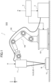
- FIG. 1 is a sectional view schematically showing a configuration of the processing system SYS of the present embodiment.
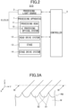
- FIG. 2 is a system configuration diagram showing a system configuration of the processing system SYS of the present embodiment.
- the processing system SYS includes a processing apparatus 1, a processing light source 2, and a controller 3.
- the processing apparatus 1 includes a processing head 11.
- the processing head 11 is attached as an end effector to an articulated robot 102 which is mounted on a self-propelled driver 101.
- the processing head 11 is configured to irradiate a processing light EL from the processing light source 2 via a beam transmission optical system 103 toward the surface of the work W placed on a stage 13.
- the controller 3 is configured to control the processing head 11, the self-propelled driver 101, the articulated robot 102, and the processing light source 2.
- the beam transmission optical system 103 transmits the processing light EL from the processing light source 2 that supplies the processing light EL to the processing head 11.
- the processing head 11 irradiates the processing light EL from the beam transmission optical system 103 toward the surface of the work W placed on the stage 13, based on the command from the controller 3 (see arrow R in FIG. 1 ).
- the articulated robot 102 changes the position and posture of the processing head 11 relative to the surface of the work W, based on the command from the controller 3, to change the position at which the processing light EL is irradiated onto the surface of the work W and the irradiation direction of the processing light EL to the surface.
- the self-propelled driver 101 changes the positions and postures of the articulated robot 102 and the processing head 11 attached to the articulated robot 102, with respect to the surface of the work W, based on the command from the controller 3, to change the position at which the processing light EL is irradiated onto the surface of the work W and the irradiation direction of the processing light EL to the surface.
- the details of the configuration of the processing head 11 are described hereinafter with reference to FIGS. 2 to 6 .
- the processing apparatus 1 is capable of processing the work W, which is an object to be processed (also referred to as a base material) as a body, under the control of the controller 3.
- the work W may be, for example, a metal, an alloy (e.g., duralumin, etc.), a semiconductor (e.g., silicon), a resin, a composite material such as CFRP (Carbon Fiber Reinforced Plastic), etc., a paint (as one example, a paint layer applied to a substrate), a glass, or an object including any material(s).
- the surface of the work W may be coated with a film made of a material different from the work W.
- the surface of the film formed as a coating on the surface of the work W may be a surface to be processed by the processing apparatus 1.
- the processing apparatus 1 may be considered to process the work W (i.e., process the work W coated with the film).
- the processing apparatus 1 irradiates the processing light EL onto the work W to process the work W.
- the processing light EL may be any type of light as long as it can process the work W by the irradiation onto the work W.
- the explanation will proceed by using an example where the processing light EL is laser light.
- the processing light EL may be any type of light other than laser light.
- the wavelength of the processing light EL may be any wavelength as long as it can process the work W by the irradiation onto the work W.
- the processing light EL may be visible light or invisible light (e.g., at least one of infrared light, ultraviolet light, extreme ultraviolet light, etc.).
- the processing light EL includes pulsed light (e.g., pulsed light with a pulse width of sub-picosecond). This pulse width is the emission time of the pulsed light. However, the processing light EL need not include pulsed light. In other words, the processing light EL may be continuous light.
- the processing light EL is supplied to the processing apparatus 1 from the processing light source 2 which generates the processing light EL, via a light transmission member (e.g., at least one of an optical fiber or a mirror) not shown in the drawings.
- the processing apparatus 1 irradiates the processing light EL, which is supplied from the processing light source 2, onto the work W.
- the processing light source 2 may include a laser light source (e.g., semiconductor laser such as laser diode (LD: Laser Diode)).
- the laser light source may include at least one of fiber laser, CO2 laser, YAG laser, excimer laser, etc.
- the processing light source 2 may include any light source (e.g., at least one of LED (Light Emitting Diode), discharge lamp, etc.).
- the processing apparatus 1 may perform a removal processing to remove a part of the work W by irradiating the processing light EL onto the work W.
- the processing apparatus 1 may perform a removal processing to remove a part of the work W by using a principle of thermal processing. Specifically, when the processing light EL is irradiated onto the surface of the work W, energy of the processing light EL is transmitted to an irradiated portion of the work W onto which the processing light EL has been irradiated, and to a proximate portion of the work W that is in proximity to the irradiated portion.
- the heat caused by the energy of the processing light EL melts a material that constitutes the irradiated portion and the proximate portion of the work W.
- the melted material disperses as droplets.
- the melted material evaporates by the heat caused by the energy of the processing light EL.
- the processing light EL may contain a pulsed light with a pulse width of milliseconds or longer or continuous light.
- the processing apparatus 1 may perform a removal processing to remove a part of the work W by using the principle of non-thermal processing (e.g., ablation processing). That is, the processing apparatus 1 may perform non-thermal processing (e.g., ablation processing) against the work W.
- non-thermal processing e.g., ablation processing
- the material constituting the irradiated portion and the proximate portion of the work W evaporates and scatters instantly. That is, the material constituting the irradiated portion and the proximate portion of the work W evaporates and scatters within a time that is sufficiently shorter than the thermal diffusion time of the work W.
- the material constituting the irradiated portion and the proximate portion of the work W may be released from the work W as at least one of ion, atom, radical, molecule, cluster, or solid fragment.
- the processing light EL may include a pulsed light with a pulse width of sub-picosecond (or in some cases, sub-nanosecond or sub-femtosecond).
- the material constituting the irradiated portion and the proximate portion of the work W may sublimate without going through a melted condition. Therefore, it becomes possible to process the work W, while minimizing the effect of heat caused by energy of the processing light EL on the work W.
- the processing apparatus 1 may form a riblet structure RB (see FIG. 3 , etc.) on the surface of the work W by conducting the removal processing.
- the processing for forming the riblet structure RB may be referred to as riblet processing.
- the processing apparatus 1 may perform the riblet processing on the surface of the work W.
- the riblet structure RB may include an uneven structure that is capable of reducing the resistance (in particular, at least one of frictional resistance or turbulent frictional resistance) of the surface of the work W against the fluid. Therefore, the riblet structure RB may be formed on the work W having a member disposed or located in the fluid. In other words, the riblet structure RB may be formed on the work W having a member that moves relative to the fluid.
- the "fluid” mentioned here means a medium (e.g., at least one of gas or liquid) flowing relative to the surface of the work W.
- the condition where the medium stands still may mean a condition where the medium stands still relative to a predetermined reference object (e.g., the ground surface).
- the riblet structure RB including a structure capable of reducing resistance (in particular, at least one of frictional resistance or turbulent frictional resistance) of the surface of the work W relative to fluid is formed on the work W
- the work W becomes easier to move relative to fluid. This reduces the resistance that hinders the movement of the work W relative to the fluid, thereby leading to energy saving. That is, it becomes possible to manufacture a turbine blade as one example of the work W that is environmentally friendly. With this, it is possible to meet Goal 7 "Energy for all and clean" of Sustainable Development Goals (SDGs) led by the United Nations and to contribute to Target 7.3 "By 2030, double the global rate of improvement in energy efficiency".
- SDGs Sustainable Development Goals
- the riblet structure RB may be formed on a work W other than the turbine blade.
- One example of the work W on which the riblet structure RB is formed may be at least one of a turbine vane, which may be referred to as a stator blade, a fan, an impeller, a propeller, or a pump.
- a fan is a member (typically a rotating body) to form a flow of gas and is used for blowers, etc.
- An impeller is a member used for, for example, pumps, and rotatable so that the pump generates a force to discharge (or suck out) fluid.
- a propeller is, for example, a member (typically, a rotating body) to convert the rotational power from a prime mover including at least one of engine or motor to propulsion power for a moving object including at least one of airplane, ship, etc.
- a prime mover including at least one of engine or motor
- propulsion power for a moving object including at least one of airplane, ship, etc.
- Another example of the work W on which the riblet structure is formed may be a body (e.g., airframe or hull) of a moving object including at least one of airplane, ship, etc.
- the riblet structure RB may have a structure including raised structure bodies 81.
- the raised structure bodies 81 extend in a first direction along the surface of the work W and are arranged in a second direction that is along the surface of the work W and crosses the first direction.
- the riblet structure RB may have a structure including the plurality of raised structure bodies 81 that are formed to respectively extend in the first direction and are aligned in the second direction.
- the riblet structure RB has a structure including the raised structure bodies 81 that respectively extend in the X-axis direction and are arranged in the Y-axis direction relative to each other.
- the raised structure bodies 81 are structure bodies that project along directions that cross both of the first direction (direction in which the raised structure bodies 81 extend) and the second direction (direction in which the raised structure bodies 81 are arranged). Each of the raised structure bodies 81 is a structure body that projects from the surface of the work W. In an example shown in FIGS. 3A , 3B, and 3C , the raised structure body 81 projects in the Z-axis direction.
- the raised structure body 81 may have a projection-shaped structure, with a projection(s) relative to the surface of the work W.
- the raised structure body 81 may have an elevated structure with an elevation(s) relative to the surface of the work W.
- the raised structure body 81 may have a mountain-shape structure with a mountain(s) relative to the surface of the work W. Between adjacent raised structure bodies 81, there is formed a valley structure 82 that is recessed relative to the surrounding. Therefore, the riblet structure RB may have a structure including the valley structure 82 that extend in the first direction along the surface of the work W and are arranged along the surface of the work W in the second direction crossing the first direction. In other words, the riblet structure RB may have a structure including the plurality of valley structures 81 that respectively extend in the first direction and are aligned along the second direction. In an example shown in FIGS.
- the riblet structure RB has a structure including the valley structures 82 that extend in the X-axis direction and are arranged in the Y-axis direction.
- the valley structure 82 may be referred to as a valley-shaped structure body.
- the raised structure body 81 may be regarded as a structure projecting from the valley structure 82.
- the raised structure body 81 between adjacent two valley structures 8 2 may be regarded as a structure that forms a projection-shaped structure, a raised-shaped structure, or a mountain-shaped structure.
- the valley structure 82 may be regarded as being a structure that is sunken from the raised structure body 81.
- the valley structure 82 may be regarded as a structure that forms a valley-shaped structure between adjacent two raised structure bodies 81.
- the valley structure 82 may be referred to as a valley-like structure body.
- At least one height H_rb of the plurality of raised structure bodies 81 may be set at a height that is determined in accordance with a pitch P_rb of the raised structure bodies 81.
- at least one height H_rb of the plurality of raised structure bodies 81 may be equal to or less than the pitch P_rb of the raised structure bodies 81.
- at least one height H_rb may be a half or less of the pitch P_rb of the raised structure bodies 81.
- the pitch P_rb of the raised structure bodies 81 may be greater than 5 ⁇ m and less than 200 ⁇ m. In this case, at least one height H_rb may be greater than 2.5 ⁇ m and less than 100 ⁇ m.
- the processing apparatus 1 For processing of the riblet structure RB on the work W, as shown in FIGS. 1 and 2 , the processing apparatus 1 includes the processing head 11, a head drive system 12 (the self-propelled driver 101 and the articulated robot 102 in an example of FIG. 1 ), the stage 13, and a stage drive system 14.
- the processing head 11 irradiates the processing light EL from the processing light source 2 onto the work W.
- the processing head 11 includes a processing optical system 15 for irradiating the processing light EL onto the work W.
- the processing head 11 irradiates the processing light EL onto the work W through the processing optical system 15.
- the processing optical system 15 may form the riblet structure RB onto the surface of the work W by forming interference fringes IS (see FIG. 4 , etc.) on the surface of the work W.
- the processing optical system 15 irradiates a plurality of processing lights (two processing lights EL in the example shown in FIG. 1 ) generated by splitting the processing light EL from the processing light source 2, onto the work W from different incident directions, respectively.
- the plurality of processing lights EL interfere with each other, generating interference light.
- the processing optical system 15 substantially irradiates the interference light generated by the interference of the plurality of processing lights EL, onto the work W.
- the interference fringes IS caused by the interference light are formed on the surface of the work W. Since a detailed structure of the processing optical system 15 is described hereinafter in detail with reference to FIG. 5 , etc., its explanation is omitted here.
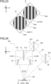
- the interference fringes IS may be fringes including bright parts IL and dark parts ID.
- the bright part IL may include a part of the interference fringes IS, where fluence is greater (i.e., higher) than a predetermined amount.
- the bright part IL may include a part that is irradiated with a light segment of the interference light, which forms the interference fringes IS, where the fluence is greater than a predetermined amount.
- the dark part ID may include a part of the interference fringes IS, where fluence is less (i.e., lower) than a predetermined amount.
- the dark part ID may include a part that is irradiated with a light segment of the interference light, which forms the interference fringes IS, where the fluence is less than a predetermined amount.
- the fluence of the bright part IL may be greater than that of the dark part ID.
- FIG. 4 further shows a relation between the interference fringes IS and the riblet structure RB.
- the bright part IL may be used mainly for forming the valley structure 82.
- the processing optical system 15 may form the valley structures 82, which constitute the riblet structure RB, on the surface of the work W, by forming, on the surface of the work W, the bright parts IL included in the interference fringes IS to remove a portion of the work W.
- the processing optical system 15 may form the valley structure 82 on the surface of the work W by irradiating a light segment of the interference light, which forms the bright parts IL, onto the surface of the work W to remove a portion of the work W.
- the processing optical system 15 may form the valley structures 82 on the surface of the work W by using the processing light EL, which reaches the bright parts IL (i.e., using a light segment of the processing light EL, which reaches the bright parts IL), to remove a portion of the work W.
- the interference fringes IS may include fringes where the bright parts IL extend along the direction (X-axis direction in the example of FIG. 4 ), in which the valley structure 82 extends, and are arranged along the direction (Y-axis direction (fringe pitch direction) in the example of FIG. 4 ) in which the valley structures 82 are aligned.
- the interference fringes IS may include fringes where the plurality of bright parts IL extend in the direction (X-axis direction in the example of FIG. 4 ), in which the valley structures 82 extend, and are aligned along the direction (Y-axis direction (fringe pitch direction) in the example of FIG. 4 ) in which the valley structures 82 are aligned.
- the dark part ID may be used mainly for forming the raised structure body 81.
- the processing optical system 15 may form the raised structure bodies 81, which constitute the riblet structure RB, on the surface of the work W by forming the dark parts ID, included in the interference fringes IS, on the surface of the work W to remove a portion of the work W (or, in some cases, not to remove a portion of the work W).
- the processing optical system 15 may form the raised structure body 81 on the surface of the work W by irradiating a light segment of the interference light, which forms the dark parts ID, onto the surface of the work W to remove a portion of the work W.
- the processing optical system 15 may form the raised structure bodies 81 on the surface of the work W by using the processing light EL, which reaches the dark parts ID (i.e., using a light segment of the processing light EL, which reaches the dark parts ID), to remove a portion of the work W.
- the interference fringes IS may include the plurality of fringes in which the dark parts ID extending along the direction (X-axis direction in the example of FIG. 4 ), in which the raised structure body 81 extends, are arranged along the direction (Y-axis direction in the example of FIG. 4 ) in which the raised structure bodies 81 are arranged.
- the interference fringes IS may include fringes in which the plurality of dark parts ID extending in the direction (X-axis direction in the example of FIG. 4 ), in which the raised structure bodies 81 extend, are aligned along the direction (Y-axis direction in the example of FIG. 4 ) in which the raised structure bodies 81 are aligned.
- the head drive system 12 moves the processing head 11 along at least one of X-axis direction, Y-axis direction, or Z-axis direction under the control of the controller 3.
- the head drive system 12 may move the processing head 11 along at least one of ⁇ X direction, ⁇ Y direction, or ⁇ Z direction besides or as an alternative to at least one of X-axis direction, Y-axis direction, or Z-axis direction.
- the processing head 11 forms the interference fringes IS on the work W
- the stage 13 and the work W changes.
- the work W is placed.
- the stage 13 need not hold the work W placed on the stage 13.
- the stage 13 need not add a holding power for holding the work W, to the work W placed on the stage 13.
- the stage 13 may hold the work W placed on the stage 13.
- the stage 13 may add a holding power for holding the work W, to the work W placed on the stage 13.
- the stage 13 may hold the work W by vacuum and/or electrostatic suction.
- a jig for holding the work W may hold the work W
- the stage 13 may hold the jig holding the work W.
- the stage drive system 14 moves the stage 13 under the control of the controller 3. Specifically, the stage drive system 14 moves the stage 13 relative to the processing head 11. For example, under the control of the controller 3, the stage drive system 14 may move the stage 13 along at least one of X-axis direction, Y-axis direction, Z-axis direction, ⁇ X direction, ⁇ Y direction, or ⁇ Z direction. Moving the stage 13 along at least one of ⁇ X direction, ⁇ Y direction, or ⁇ Z direction may be regarded as being equivalent to changing the posture of the stage 13 (and the work W placed on the stage 13) around at least one of X-axis, Y-axis, or Z-axis.
- moving the stage 13 along at least one of ⁇ X direction, ⁇ Y direction, or ⁇ Z direction may be regarded as being equivalent to rotating (or rotationally moving) the stage 13 around at least one of X-axis, Y-axis, or Z-axis.
- the processing system SYS may change a positional relation between the work W placed on the stage 13 and the processing head 11 by moving both of the stage 13 and the processing head 11 under the control of the controller 3. Furthermore, the processing system SYS may move the interference fringes IS relative to the work W without moving the processing head 11 and the stage 13.
- the controller 3 controls operation of the processing system SYS.
- the controller 3 may generate the processing control information for processing the work W and may control the processing apparatus 1 based on the processing control information to process the work W in accordance with the generated processing control information.
- the controller 3 may control processing of the work W.
- the controller 3 may include, for example, a processor and a storage.
- the processor may include, for example, at least one of CPU (Central Processing Unit) or GPU (Graphics Processing Unit)).
- the controller 3 functions as a device that controls the operation of the processing system SYS by having the processor execute a computer program.
- This computer program is a computer program to make the controller 3 (e.g., processor) perform (i.e., execute) the operations that should be performed by the controller 3.
- the computer program is designed to enable the controller 3 to cause the processing system SYS to perform the operations described later.
- the computer program to be executed by the processor may be recorded in the storage (i.e., storage medium) of the controller 3 or may be recorded in any storage medium (e.g., hard disk or semiconductor memory) that is built in the controller 3 or may be externally attached to the controller 3.
- the processor may download the computer program to be executed from a device outside of the controller 3 via a network interface.
- the controller 3 need not be provided inside the processing system SYS.
- the controller 3 may be installed outside the processing system SYS as a server, etc.
- the controller 3 and the processing system SYS may be connected by a wired and/or wireless network (or data bus and/or communication lines).
- a wired network it is optional to use a network that uses a serial bus interface represented by, for example, at least one of IEEE1394, RS-232x, RS-422, RS-423, RS-485, or USB.
- a wired network it is optional to use a network that uses a parallel bus interface.
- wired network it is optional to use a network that uses an interface based on Ethernet (registered trademark) represented by at least one of 10BASE-T, 100BASE-TX, or 1000BASE-T.
- a wireless network it is optional to a network using radio waves.
- IEEE802.1x e.g., at least one of wireless LAN or Bluetooth (registered trademark)
- a wireless network it is optional to use a network using infrared rays.
- a wireless network it is optional to use a network using optical communication.
- the controller 3 and the processing system SYS may be configured to be able to send and receive various types of information via the network.
- the controller 3 may be able to send information, such as commands, control parameters, etc., to the processing system SYS via the network.
- the processing system SYS may include a receiver that receives information, such as commands, control parameters, etc., from the controller 3 via the network.
- an arithmetic model that can be constructed by machine learning may be implemented by the processor executing a computer program.
- an arithmetic model that can be constructed by machine learning it is possible to cite, for example, an arithmetic model including a neural network (so-called Artificial Intelligence (AI)).
- learning of the arithmetic model may include learning of parameters (at least one of weight or bias) of the neural network.
- the controller 3 may control the operation of the processing system SYS by using an arithmetic model.
- the operation to control the operation of the processing system SYS may include the operation to control the operation of the processing system SYS by using an arithmetic model.
- the controller 3 may implement an arithmetic model that has already been constructed by offline machine learning using teacher data.
- the arithmetic model implemented in the controller 3 may be updated by online machine learning on the controller 3.
- the controller 3 may control the operation of the processing system SYS by using an arithmetic model that has been implemented in an external device of the controller 3 (i.e., a device provided outside the processing system SYS).
- a recording medium for recording a computer program to be executed by the processor it is optional to use at least one of optical disk such as CD-ROM, CD-R, CD-RW, flexible disk, MO, DVD-ROM, DVD-RAM, DVD-R, DVD+R, DVD-RW, DVD+RW, Blue-ray(registered trademark); magnetic medium such as magnetic tape; magneto-optical disk; semiconductor memory such as USB memory; or any other medium capable of storing programs.
- the recording medium may include a device capable of recording computer programs (e.g., a general-purpose or dedicated device in which the computer program is implemented in the form of at least one of software, firmware, etc.).
- each processing or function, included in the computer program may be realized by a logical processing block that is realized in the controller 3 (i.e., a computer) by the controller 3 executing the computer program, may be realized by hardware such as a predetermined gate array (FPGA and ASIC) provided by the controller 3, or may be realized in the form of a mixture of a logical processing block(s) and a partial hardware module(s) that realizes some elements of the hardware.
- a logical processing block that is realized in the controller 3 (i.e., a computer) by the controller 3 executing the computer program
- hardware such as a predetermined gate array (FPGA and ASIC) provided by the controller 3
- FPGA and ASIC predetermined gate array
- the processing optical system 15 that forms the interference fringes IS on the surface of the work W is explained.
- the processing optical system 15 includes a first optical system 16, a second optical system 17, and a third optical system 18.
- the first optical system 16 splits the processing light EL, which is generated by the processing light source 2, into two processing lights EL, and one of them is irradiated from the third optical system 18 onto the work W.
- the second optical system 17 splits the other of the split processing lights EL to generate a plurality of processing lights EL (two processing lights EL in the example shown in FIG. 1 ) and irradiate them onto the work W from different directions, respectively.
- the processing optical system 15 substantially irradiates the interference light, which is generated by the interference of the plurality of processing lights EL, onto the work W.
- the interference fringes IS caused by the interference light are formed by the second optical system 17 in an interference area IA on the surface of the work W, and the processing light EL is irradiated from the third optical system 18 onto the interference area IA.
- each processing light EL is distinguished by referring to it, as follows.
- the processing light EL generated by the processing light source 2 is referred to as a processing light EL0.
- a light that is separated from the processing light EL0 by the first optical system 16 and then is directed toward the third optical system 18 is referred to as a first processing light EL1.
- a light that is separated from the processing light EL0 by the first optical system 16 and then is directed toward the second optical system 17 is referred to as a second processing light EL2.
- Lights that are split from the second processing light EL2 by the second optical system 17 and then are irradiated onto the work W are referred to as second processing lights EL22.
- the first processing light EL1 from the first optical system 16, which is irradiated by the third optical system 18 onto the work W is referred to as a first processing light EL11.
- the first optical system 16 can also be referred to as a splitting optical system, since it splits the processing light EL0 from the processing light source 2 to generate the first and second processing lights EL1, EL2 as pulsed lights of which emission durations at least partially overlap.
- the second optical system 17 can also be referred to as an interference fringe formation optical system, which forms the interference fringes IS on the surface of the work W by irradiating the plurality of second processing lights EL22, which have been generated by splitting the second processing light EL2, onto the work W from different incident directions respectively.
- the third optical system 18 can also be referred to as an irradiation optical system, which irradiates the first processing light EL11 from the first processing light EL1 toward the interference area IA in which the interference fringes IS are formed.
- the processing optical system 15 forms the interference fringes IS by irradiating the plurality of second processing lights EL22 from the second optical system 17 onto the work W from different incident directions, respectively.
- the number of the processing lights EL22 may be an integer of 2 or more, as long as they form the interference fringes IS.
- the fluence distribution of the processing light changes in the interference area IA where the interference fringes IS are formed on the surface of the work W, as compared with the comparative example where the first processing light EL11 is not irradiated.
- FIG. 6A shows the fluence distribution of the processing light in the comparative example
- FIG. 6B shows the fluence distribution of the processing light in the present embodiment. As shown in FIGS. 6A and 6B , the minimum fluence of the processing light becomes higher in the present embodiment, as compared with the comparative example.
- the minimum fluence may be the minimum value of the fluence of the processing light in the dark part ID of the interference fringes IS.
- the minimum fluence may be the minimum value of the fluence of the processing light that reaches the dark part ID of the interference fringes IS.
- the reason why the minimum fluence of the present embodiment becomes larger than that of the comparative example is that an overlapped irradiation of the plurality of second processing lights EL22 and the first processing light EL11 provides the processing light with a light component that does not affect the formation of the interference fringes IS, but affects the fluence distribution.
- the processing optical system 15 provides the interference light with a light component (so-called DC component of the fluence distribution of the interference fringes IS) that does not affect the formation of the interference fringes IS, but affects the fluence distribution, by an overlapped irradiation of the plurality of second processing lights EL22 and the first processing light EL11.
- the processing optical system 15 provides the interference light with the DC component of the fluence distribution of the interference fringes IS by an overlapped irradiation of the plurality of second processing lights EL22 and the first processing light EL11, without affecting a contrast component (i.e., a component affecting shading (tone) of the interference fringes IS) of the fluence distribution that affects the formation of the interference fringes IS.
- a contrast component i.e., a component affecting shading (tone) of the interference fringes IS
- the processing optical system 15 may irradiate the first processing light EL11 to overlap the plurality of second processing lights EL22, so as not to affect the formation of the interference fringes, but to provide the interference light with a light component that affects the fluence distribution.
- the processing optical system 15 may irradiate the first processing light EL11 to overlap the plurality of second processing lights EL22, so as not to affect the formation of the interference fringes IS, but to provide the interference light with a light component that increases the minimum fluence.
- the first processing light EL11 (its fluence), which is irradiated to overlap the plurality of second processing lights EL22, may be set so as not to affect the formation of the interference fringes IS, but to make it possible to provide the interference light with a light component that affects the fluence distribution.
- the first processing light EL11 (its fluence), which is irradiated to overlap the second processing lights EL22, may be determined, based on at least one of a characteristic of the processing light EL0, a characteristic of the interference light, a characteristic of the work W, or a characteristic of the riblet structure RB.
- the first processing light EL11 (its fluence), which is irradiated to overlap the second processing lights EL22, may be determined, based on the result of an experiment or simulation that forms the riblet structure RB on the work W by forming the interference fringes IS.
- the shape of a tip of the raised structure body 81 may become a flat shape. This is because, as mentioned above, the minimum fluence is relatively small in the comparative example. Therefore, as shown in FIG. 6A , in the comparative example, there is a relatively high possibility that the fluence of at least a portion of the dark part ID of the interference fringes IS becomes smaller than the lower limit value TH_lowest of the fluence at which the work W can be processed (that is, a part of the work W can be removed).
- the processing apparatus 1 of the present embodiment can make the shape of the riblet structure RB become closer to or conform to an ideal shape.
- the processing apparatus 1 can form a riblet structure RB having a shape that is close to or conforms to an ideal shape.
- the processing apparatus 1 may be regarded as adjusting the shape of the riblet structure RB such that the shape of the riblet structure RB to be formed on the work W becomes a predetermined shape that is closer to an ideal shape than the shape of the riblet structure RB to be formed in the comparative example, by irradiating the first processing light EL11 to overlap the plurality of second processing lights EL22.
- the processing apparatus 1 can enjoy the effect of being capable of properly processing the work W to form a riblet structure RB having a shape that is close to or conforms to an ideal shape.
- the processing optical system 15 may set the first processing light EL11 (its fluence) that is irradiated to overlap the plurality of second processing light EL22, such that the minimum fluence of the processing light is set to be equal to or greater than the lower limit value TH_lowest.
- the processing optical system 15 may set the first processing light EL11 (its fluence) that is irradiated to overlap the plurality of second processing lights EL22, such that the minimum fluence of the processing light is set at a fluence at which the work W can be processed.
- the first processing light EL11 (its fluence), which is irradiated to overlap the plurality of second processing lights EL22, may be set such that the minimum fluence of the processing light is set at a fluence at which the work W can be processed. As a result, the above effect becomes properly enjoyable.
- the amount of processing in a first part of the work W, where a light portion of the processing light having a fluence smaller than the predetermined threshold Fth is irradiated becomes different from the amount of processing in a second part of the work W, where a light portion of the processing light having a fluence larger than the predetermined threshold Fth is irradiated.
- the ratio of the increase in the amount of processing to the increase in fluence in the second relation is larger than the ratio of the increase in the amount of processing to the increase in fluence in the first relation.
- the amount of processing in the first part of the work W, where a light portion of the processing light having a fluence smaller than the predetermined threshold Fth is irradiated becomes smaller than the amount of processing in the second part of the work W, where a light portion of the processing light having a fluence larger than the predetermined threshold Fth is irradiated.
- the amount of processing in the first part of the work W becomes insufficient and/or the amount of processing in the second part of the work W becomes excessive. Therefore, there is a possibility that the precision of the shape of the riblet structure RB to be formed on the work W becomes worse. For example, as shown in a lower part of FIG.
- the shape of the tip of the raised structure body 81 which is formed mainly by a light portion of the processing light where the fluence is relatively small (e.g., a light portion irradiated onto the dark part ID), becomes flat.
- the processing optical system 15 may set the first processing light EL11 (its fluence) irradiated to overlap the plurality of second processing lights EL22, such that the minimum fluence of the interference light becomes equal to or greater than the predetermined threshold Fth.
- the processing optical system 15 may set the first processing light EL11 (its fluence) irradiated to overlap the plurality of second processing lights EL22, such that the minimum fluence of the interference light becomes equal to or greater than a threshold that is obtained by adding a predetermined margin to the predetermined threshold Fth.
- the processing optical system 15 may set the first processing light EL11 (its fluence) irradiated to overlap the plurality of second processing lights EL22, such that the minimum fluence of the interference light becomes equal to or greater than a threshold to be set based on the predetermined threshold Fth.
- a threshold to be set based on the predetermined threshold Fth.
- an object (the work W in the embodiment) has a characteristic in which a first relation between the fluence and the amount of processing, in case that the fluence of each processing light is smaller than a predetermined threshold, becomes different from a second relation between the fluence and the amount of processing, in case that the fluence of each processing light is larger than the predetermined threshold.
- the ratio of the increase in the amount of processing to the increase in fluence of the processing light in the second relation is larger than the ratio of the increase in the amount of processing to the increase in fluence of the processing light in the first relation.
- the second optical system 17 sets the first processing light EL from the third optical system 18, such that the minimum fluence of the processing light reaching the dark part of the interference fringes becomes equal to or greater than the predetermined threshold.
- the ideal waveform Wi can be shown as sinusoidal waveforms by a Fourier transform.
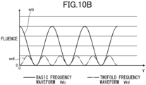
- FIGS. 10A and 10B show an ideal waveform Wi as one example.
- FIG. 10B shows two waveforms (basic frequency waveform Wb and twofold frequency waveform Wd) obtained by conducting the Fourier transform on the ideal waveform Wi. Therefore, the ideal waveform Wi of FIG. 10A is one obtained by superposition of the basic frequency waveform Wb and the twofold frequency waveform Wd of FIG. 10B .
- the processing optical system 15 processes the work W by forming interference fringes IS (hereinafter also referred to as interference fringes IS1) showing the basic frequency waveform Wb and processes the work W by forming interference fringes IS (hereinafter also referred to as interference fringes IS2) showing the twofold frequency waveform Wd, thereby forming a riblet structure RB of ideal shape.
- the processing optical system 15 forms interference fringes IS that substantially show the ideal waveform Wi by using the interference fringes IS1 and the interference fringes IS2, thereby forming a riblet structure RB of ideal shape.
- the processing optical system 15 can also form the interference fringes IS1 and the interference fringes IS2, in place of forming the interference fringes IS showing the ideal waveform Wi, to form a riblet structure RB of ideal shape.
- the ideal waveform Wi changes depending on the shape that the riblet structure RB is required to have.
- the number and type (multiples of frequency, amplitude, etc.) of sinusoidal waveforms obtained by the Fourier transform also change together. Therefore, it suffices that the processing optical system 15 suitably sets the shape of the basic frequency waveform Wb and the number and shape of n-fold frequency waveform Wn to be superposed on the basic frequency waveform Wb, in accordance with the ideal waveform Wi that has been set to form the required riblet structure RB.
- the processing optical system 15 can make a superposition of the basic frequency waveform Wb, which has been obtained by conducting the Fourier transform on the ideal waveform Wi, and at least one n-factor frequency waveform Wn, which has been obtained by conducting the Fourier transform in the same manner. Furthermore, the processing optical system 15 may make a superposition of the basic frequency waveform Wb, which has been obtained by conducting the Fourier transform on the ideal waveform Wi, and two n-factor frequency waveforms Wn, which have been obtained by conducting the Fourier transform in the same manner.
- the processing optical system 15 may make a superposition of the basic frequency waveform Wb, which has been obtained by conducting the Fourier transform on the ideal waveform Wi, and at least three n-factor frequency waveforms Wn, which have been obtained by conducting the Fourier transform in the same manner.
- the processing optical system 15 splits, in the first optical system 16, the processing light EL0 from the processing light source 2 into the first and second processing lights EL1, EL2.
- the second optical system 17 generates the basic frequency waveform Wb and the plurality of n-fold frequency waveforms Wn as the second processing lights EL22 from the second processing light EL2 and irradiates them onto the work W from different incident directions, respectively, thereby forming the interference fringes IS per frequency.
- the third optical system 18 irradiates the first processing light EL1 as the first processing light EL11 to overlap each second processing light EL22 in the interference area IA where each interference fringe IS is formed.
- the second optical system 17 can change at least one of amplitude or period in the interference fringes IS by changing the incident angle of the plurality of second processing lights EL22 to be emitted. With this, it can form interference fringes IS of the basic frequency waveform Wb and the n-fold frequency waveform Wn.
- the second optical system 17 can adjust at least one of amplitude or period in the interference fringes IS by changing the incident angle of the plurality of second processing lights EL22 to be emitted. With this, it can make appropriate the basic frequency waveform Wb and the n-fold frequency waveform Wn.
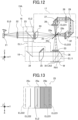
- This irradiatable area includes the area, where the first processing light EL11 and the second processing lights EL22 can be irradiated at once (at the same time), and the total of the area, where the first processing light EL11 and the processing lights EL22 are irradiated by scanning or sweeping (changing the irradiation position of) the first processing light EL11 and the second processing lights EL22 by the galvanometer mirror 21 (see FIG. 12 , etc.), etc.
- the processing area PA is an area where the work W placed on the stage 13 can be irradiated with the first processing light EL11 and the second processing lights EL22, without a relative movement of the stage 13 and the processing optical system 15 (processing head 11).
- the galvanometer mirror 21 functions as an interference fringe moving member that moves the position of the interference range IA relative to the second optical system 17 in a direction that crosses and typically is perpendicular to the optical axis of the second optical system 17.
- This galvanometer mirror 21 as the interference fringe moving member has a function that also moves the irradiation area RA in a direction that crosses and typically is perpendicular to the optical axis of the second optical system 17.
- This scanning range may be smaller than the processing area PA (may process only a part of the processing area PA).
- the processing area PA may be set to be smaller than an area where the first processing light EL11 or the second processing lights EL22 can actually be scanned. In this case, the scanning area may be larger than the processing area PA (the first processing light EL11 or the second processing lights EL22 may be irradiated onto an area wider than the processing area PA).
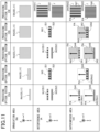
- FIG. 11 shows five examples of the processing method using a processing optical system 15A, a processing optical system 15B, a processing optical system 15C, a processing optical system 15D, and a processing optical system 15E, in this order from the left side.
- the upper row shows modes of the irradiation area RA by the first processing light EL11
- the middle row shows modes of the interference area IA (interference fringes IS) by the second processing lights EL22
- the lower row shows modes of the irradiation area RA and the interference area IA (the superimposed area OA) in the processing area PA.
- the interference area IA1 where the interference fringes IS1 showing the basic frequency waveform Wb are formed
- the irradiation area RA1 which is formed by irradiating the first processing light EL11.
- an area, where the interference area IA1 and the irradiation area RA1 are superimposed, is also referred to as a superimposed area OA1.
- the superimposed area OA1 is scanned over the entire processing area PA.
- the entire processing area PA is scanned by forming the superimposed area OA1 by superimposing the interference area IA1 and the irradiation area RA1 at one end in the X-axis direction in the processing area PA and then moving the superimposed area OA1 toward the other end in the X-axis direction.
- a superimposed area OA2 is formed by superimposing the interference area IA2 where the interference fringes IS2 showing the twofold frequency waveform Wd are formed, and the irradiation area RA1 caused by irradiating the first processing light EL11.
- the entire processing area PA is scanned with the superimposed area OA2 including the twofold frequency waveform Wd, similar to the superimposed area OA1 including the basic frequency waveform Wb.
- the irradiation area RA (hereinafter referred to as irradiation area RA2) of the first processing light EL11 by the third optical system 18 is made to be smaller than the processing area PA.
- the irradiation area RA2 is made to be a rectangular shape where the dimension is equal to the processing area PA in the Y-axis direction and where the dimension is smaller than the processing area PA in the X-axis direction.
- the interference area IA3 where the interference fringes IS1, IS2 of the two-types frequency waveforms Wb, Wd are formed into alignment with each other, and the irradiation area RA2 which is formed by irradiating the first processing light EL11.
- an area where the interference area IA3 and the irradiation area RA2 are superimposed is also referred to as a superimposed area OA3.
- the entire processing area PA is scanned with this superimposed area OA3.
- the irradiation area RA (hereinafter referred to as irradiation area RA3) of the first processing light EL11 by the third optical system 18 is made to be the same size as that of the processing area PA. Furthermore, in the processing method by the processing optical system 15C, as shown in the middle row, the interference area IA to form the interference fringes IS by the plurality of second processing lights EL22 from the second optical system 17 is made to be smaller than the processing area PA.
- the interference area IA is made to be a rectangular shape where the dimension is equal to the processing area PA in the Y-axis direction and where the dimension is smaller than the processing area PA in the X-axis direction.
- the interference fringes IS1 showing the basic frequency waveform Wb and the interference fringes IS2 showing the twofold frequency waveform Wd are formed at different timings (time).
- the interference area IA1 where the interference fringes IS1 showing the basic frequency waveform Wb are formed, and the interference area IA2, where the interference fringes IS2 showing the twofold frequency waveform Wd are formed.
- an area where the interference area IA1 and the interference area IA2 are formed becomes a superimposed area OA where the first processing light EL11 and the plurality of second processing lights EL22 (interference fringes IS1, IS2) are superimposed.
- the entire processing area PA is scanned with the interference area IA1 or the interference area IA2, while the irradiation area RA3 is formed.
- the interference area IA1 is formed at one end in the X-axis direction in the processing area PA, and the interference area IA1 is moved toward the other end in the X-axis direction, thereby scanning the entire processing area PA to form a superimposed area OA4 in the entire processing area PA.
- the interference area IA2 is formed at one end in the X-axis direction in the processing area PA, and the interference area IA2 is moved toward the other end in the X-axis direction, thereby scanning the entire processing area PA to form a superimposed area OA5 in the entire processing area PA.
- the processing method using the processing optical system 15C it is possible to irradiate the entire processing area PA on the surface of the work W with the interference fringes IS1 showing the basic frequency waveform Wb and the interference fringes IS2 showing the twofold frequency waveform Wd.
- the entire processing area PA is scanned with the first processing light EL11. Therefore, irradiation is conducted in a manner to surely superimpose the interference fringes IS1, IS2 and the first processing light EL11.
- the irradiation area RA3 of the first processing light EL11 by the third optical system 18 is made to be the same size as that of the processing area PA.
- the interference area IA3 to form the interference fringes IS by the plurality of second processing lights EL22 from the second optical system 17 is made to be smaller than the processing area PA.
- the interference area IA3 is made to be a rectangular shape where the dimension is equal to the processing area PA in the Y-axis direction and where the dimension is smaller than the processing area PA in the X-axis direction.
- the interference fringes IS1 showing the basic frequency waveform Wb and the interference fringes IS2 showing the twofold frequency waveform Wd are formed to be aligned in the X-axis direction.
- the interference fringes IS2 of the twofold frequency waveform Wd are formed on one of the ends in the X-axis direction, and the interference fringes IS1 of the basic frequency waveform Wb are formed to be aligned therewith on the other end in the X-axis direction.
- the irradiation area RA3 is formed by irradiating the first processing light EL11 onto the processing area PA in which the interference area IA3, where the interference fringes IS1, IS2 of the two-types frequency waveforms Wb, Wd are aligned with each other, is formed.
- the irradiation area RA3 has the same size as that of the processing area PA.
- the interference area IA3 is made to be smaller than the processing area PA.
- an area where the interference area IA3 is formed becomes a superimposed area OA6 where the first processing light EL11 and the plurality of second processing lights EL22 (interference fringes IS1, IS2) are superimposed.
- the entire processing area PA is scanned with the interference area IA3, while the irradiation area RA3 is formed.
- the interference area IA3 is formed at one end in the X-axis direction in the processing area PA, and the interference area IA3 is moved toward the other end in the X-axis direction, thereby scanning the entire processing area PA to form the superimposed area OA6 in the entire processing area PA.
- the processing method using the processing optical system 15D it is possible to irradiate the entire processing area PA on the surface of the work W with the interference fringes IS1 showing the basic frequency waveform Wb and the interference fringes IS2 showing the twofold frequency waveform Wd.
- the entire processing area PA is scanned with the first processing light EL11. Therefore, irradiation is conducted in a manner to superimpose the interference fringes IS1, IS2 and the first processing light EL11.
- the irradiation area RA3 of the first processing light EL11 by the third optical system 18 is made to be the same size as that of the processing area PA.
- the interference area IA to form the interference fringes by the plurality of second processing lights EL22 from the second optical system 17 is made to be generally the same size as that of the irradiation area RA3, that is, the processing area PA. Therefore, in the processing method using the processing optical system 15E, the second optical system 17 can form the interference fringes IS in the entire processing area PA without moving the interference area IA. In other words, in the processing method using the processing optical system 15E, there does not change the positional relation (a constant positional relation) between the irradiation area RA3 by the third optical system 18 and the interference area IA formed by the second optical system 17.
- the interference fringes IS1 (hereinafter referred to as interference area IA4) showing the basic frequency waveform Wb and the interference fringes IS2 (hereinafter referred to as interference area IA5) showing the twofold frequency waveform Wd are formed at different timings (time).
- the interference area IA4 where the interference fringes IS1 showing the basic frequency waveform Wb are formed, and the irradiation area RA3 that is formed by irradiating the first processing light EL11.
- an area where the interference area IA4 and the irradiation area RA3 are superimposed is also referred to as a superimposed area OA7.
- the interference area IA5 where the interference fringes IS2 showing the twofold frequency waveform Wd are formed
- the irradiation area RA3 that is formed by irradiating the first processing light EL11.
- an area where the irradiation area RA3 is superimposed on the interference area IA5 is also referred to as a superimposed area OA8.
- the irradiation area RA3, the interference area IA4, and the interference area IA5 have the same size as that of the processing area PA. Therefore, in the superimposed areas OA6, OA7, the first processing light EL11 and the plurality of second processing lights EL22 (interference fringes IS1, IS2) are superimposed in the entire processing area PA.
- the processing method using the processing optical system 15E it is possible to irradiate the entire processing area PA on the surface of the work W with the interference fringes IS1 showing the basic frequency waveform Wb and the interference fringes IS2 showing the twofold frequency waveform Wd.
- the entire processing area PA is scanned with the first processing light EL11. Therefore, irradiation is conducted in a manner to superimpose the interference fringes IS1 or interference fringes IS2 and the first processing light EL11.
- FIGS. 12 to 21 specific configuration examples of the five processing optical systems 15A, 15B, 15C, 15D, and 15E are explained in this order by using FIGS. 12 to 21 .
- the processing light source 2 is omitted, and only the processing light EL0 from the processing light source 2 is shown.
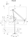
- FIG. 12 is a view showing a configuration of the processing optical system 15A.
- the processing light source 2 is omitted in FIG. 12 .
- the processing optical system 15A includes the galvanometer mirror 21 and a collimating lens 22, to allow the processing light EL0 from the processing light source 2 to proceed to the first optical system 16.
- the galvanometer mirror 21 is an interference fringe moving member that moves the position of the interference area IA relative to the second optical system 17 in a direction that crosses and is typically perpendicular to the optical axis of the second optical system 17 and reflects the processing light EL0 from the processing light source 2 toward a beam splitter 23.
- This galvanometer mirror 21 is capable of changing its inclination in the rotational direction around a rotation axis extending in the Z-axis direction.
- the galvanometer mirror 21 can change the direction of reflection of the processing light EL0 toward the beam splitter 23 by changing the inclination.
- the galvanometer mirror 21 can change the direction of reflection of the processing light EL0 within a range where the second processing light EL2 after splitting can be incident on a splitting surface 25a of the special beam splitter 25.
- the galvanometer mirror 21 can change the direction in which the processing light EL0 travels, within a range where the second processing light EL2 can be incident on the splitting surface 25a.
- This galvanometer mirror 21 may be driven under the control of the controller 3 or under the control of another controller.
- the collimating lens 22 turns the processing light EL0 from the processing light source 2, which has been reflected by the galvanometer mirror 21, into a collimated light (parallel light).
- the processing light EL0 from the processing light source 2 in this example is a diffusing (divergent) light
- such processing light EL0 is turned into a collimated light (parallel light) by the collimating lens 22.
- the processing optical system 15A includes the beam splitter 23 as the first optical system 16 which splits the processing light EL0 from the processing light source 2 into the first and second processing lights EL1, EL2.
- the processing light EL0 collimated by the collimating lens 22 is incident.
- the beam splitter 23 splits the processing light EL0 into the first and second processing lights EL 1, EL2.
- the beam splitter 23 reflects a part of the processing light EL0 to generate the first processing light EL1 which proceeds to the third optical system 18 and transmits another part of the processing light EL0 to generate the second processing light EL2 which proceeds to the second optical system 17.
- the beam splitter 23 may be one that transmits a part of the processing light EL0 to generate the first processing light EL1 and that reflects another part of the processing light EL0 to generate the second processing light EL2.
- This beam splitter 23 may be an amplitude-dividing beam splitter or polarizing beam splitter.
- the beam splitter 23 allows the second processing light EL2, which has been generated by transmitting, to proceed in parallel with the Y-axis direction to the second optical system 17. Therefore, the galvanometer mirror 21 as an interference fringe moving member is disposed in an optical path between the processing light source 2 and the beam splitter 23 as the first optical system 16 which is disposed at a position to split the processing light EL0 into the first and second processing lights EL1, EL2.
- the galvanometer mirror 21 moves the position of the interference area IA relative to the second optical system 17 in a direction that crosses (is perpendicular to) the optical axis of the second optical system 17.
- the processing light EL0 from the processing light source 2 is split into two by using a diffractive optical element (DOE) or beam splitter, which is not shown in the drawings.
- DOE diffractive optical element
- the two split processing lights EL0 are concentrated on one point or a narrow area close to that at respective different positions on the galvanometer mirror 21 (its reflection surface).
- the two processing lights EL0 are reflected by the galvanometer mirror 21 and then transmitted through the collimating lens 22.
- One of the split processing lights EL0 is reflected by the beam splitter 23 to result in the first processing light EL1.
- the other of the split processing lights EL0 is transmitted through the beam splitter 23 to result in the second processing light EL2.
- the processing optical system 15A can prevent the energy of the processing light EL0, which is from the processing light source 2, from concentrating on a narrow spot in the beam splitter 23, thereby suppressing damage to the beam splitter 23 from the processing light EL0.
- the processing optical system 15A concentrates the two processing lights EL0 at one point or a narrow area close to that of the galvanometer mirror 21 (its reflection surface). Therefore, it is possible to easily and properly adjust the change of the traveling direction of the processing light EL0 by changing the inclination of the galvanometer mirror 21.
- the processing optical system 15A includes, as the second optical system 17 to generate the plurality of second processing lights EL22 by splitting the second processing light EL2 from the first optical system 16, a first cylindrical lens 24, a special beam splitter 25, a second cylindrical lens 26, a first mirror 27, an optical deflecting member 28, a second mirror 29, a third mirror 31, a third cylindrical lens 32, and a lens 33.
- the second optical system 17 of the processing optical system 15A need not include the first cylindrical lens 24, the second cylindrical lens 26, the second mirror 29, and the lens 33.
- the first cylindrical lens 24 is an optical member that has a shape extending in the X-axis direction and a refractive power only in the Z-axis direction, thereby resulting in a convex lens in a cross-section perpendicular to the X-axis direction.
- This first cylindrical lens 24 does not change the second processing light EL2 from the first optical system 16 in the X-axis direction but condenses it in the Z-axis direction.
- the back focus in the travel direction of the second processing light EL2 is set in the vicinity of the splitting surface 25a of the special beam splitter 25. Therefore, the first cylindrical lens 24 turns the second processing light EL2 into a linear light extending in the X-axis direction on the splitting surface 25a (see FIG. 13 ).
- the special beam splitter 25 splits the second processing light EL2, which has been turned into the linear light extending in the X-axis direction by the first cylindrical lens 24, into the plurality of second processing lights EL22. Therefore, the special beam splitter 25 functions as a light-splitting member that splits the second processing light EL2 into the plurality of second processing lights EL22.
- the special beam splitter 25 splits the second processing light EL2 into the two second processing lights EL22 (when indicated separately, one is referred to as the second processing light EL221, and the other as the second processing light EL222).
- the special beam splitter 25 also has a function that combines the two split second processing lights EL22 and allows both second processing lights EL22 to proceed toward the lens 33, that is, the work W in front.
- the condensing position of the second processing light EL2 that is formed by the first cylindrical lens 24 may be slightly displaced from the special beam splitter 25 in the optical axis direction.
- This special beam splitter 25 is a rectangular plate-shaped member and is disposed to have an inclination of 45 degrees relative to the Y-axis direction around a center axis extending in the X-axis direction.
- the special beam splitter 25 includes the splitting surface 25a, a reflective surface 25b and a transmissive surface 25c, each of which extends in the X-axis direction (see FIG. 13 ).
- the splitting surface 25a is located in the vicinity of the center axis in the 45-degree inclination direction
- the reflective surface 25b is located on the upper side in the inclination direction and on the right side (close to the third cylindrical lens 32) when viewed in FIGS.
- the transmissive surface 25c is located on the lower side in the inclination direction and on the left side (close to the first cylindrical lens 24) when viewed in FIGS. 12 and 13 .
- the inclination angle of the special beam splitter 25 is not limited to 45 degrees.
- the splitting surface 25a splits the second processing light EL2, which has been turned into a linear light extending in the X-axis direction by the first cylindrical lens 24, into the plurality of second processing lights EL22.
- This splitting surface 25a includes an amplitude-dividing beam splitter or polarizing beam splitter, generates the second processing light EL221 by reflecting a part of the second processing light EL2, and generates the second processing light EL222 by transmitting another part of the second processing light EL2.
- the special beam splitter 25 is disposed to have an inclination of 45 degrees relative to the Y-axis direction.
- the second processing light EL221 resulting from reflection by the splitting surface 25a proceeds to the second cylindrical lens 26 in parallel with the Z-axis direction, and another processing light EL222 resulting from transmission through the splitting surface 25a proceeds to the third cylindrical lens 32 in parallel with the Y-axis direction.
- the reflective surface 25b reflects the second processing light EL221, resulting from reflection by the third mirror 31 and then condensing by the third cylindrical lens 32, thereby allowing it to proceed downward (toward the lens 33) in the Z-axis direction. Therefore, the reflective surface 25b is configured such that the back surface facing the side of the third cylindrical lens 32 in the special beam splitter 25 is made to have an optical characteristic to reflect light.
- This reflective surface 25b can be formed by subjecting an end portion on an upper side of the back surface of the special beam splitter 25 to a partial vapor deposition, etc. As long as the reflective surface 25b reflects the second processing light EL221 from the third cylindrical lens 32 toward the lens 33, it suffices to suitably set the configuration and the position. They are not limited to those of this example.
- the transmissive surface 25c transmits the second processing light EL222, resulting from reflection by the first mirror 27 and then condensing by the second cylindrical lens 26, thereby allowing it to proceed downward (toward the lens 33) in the Z-axis direction.
- the transmissive surface 25c of this example is made to be a void, that is, the portion corresponding to the transmissive surface 25c in the special beam splitter 25 is cut out.
- the transmissive surface 25c transmits the second processing light EL222 from the second cylindrical lens 26 toward the lens 33, it suffices to suitably set the configuration and the position. They are not limited to those of this example.
- the second cylindrical lens 26 is an optical member that has a shape extending in the X-axis direction and that has a refractive power only in the Y-axis direction, thereby resulting in a convex lens in a cross-section perpendicular to the X-axis direction.
- the front focus in the travel direction of the second processing light EL221 is set in the vicinity of the splitting surface 25a of the special beam splitter 25, thereby turning the second processing light EL221 into a collimated light (parallel light) having a predetermined size in the X-axis direction and Y-axis direction.
- the second cylindrical lens 26 allows the second processing light EL221 in the collimated condition to proceed to the first mirror 27 in parallel with the Z-axis direction. Furthermore, the second cylindrical lens 26 does not change the second processing light EL222, which has been reflected by the first mirror 27, in the X-axis direction, but condenses it in the Y-axis direction, thereby turning it into a linear light extending in the X-axis direction on the transmissive surface 25c, as mentioned hereinafter (see FIG. 13 ).
- the first mirror 27 is a plate-shaped member and is disposed to have an inclination of 45 degrees relative to the Z-axis direction around a center axis extending in the X-axis direction.
- the first mirror 27 reflects the second processing light EL221 from the second cylindrical lens 26, thereby allowing it to proceed to the optical deflecting member 28 in parallel with the Y-axis direction.
- the first mirror 27 reflects the second processing light EL222 from the second mirror 29, which has been transmitted through the optical deflecting member 28, thereby allowing it to proceed to the second cylindrical lens 26.
- the optical deflecting member 28 is a member that changes (deflects) the travel directions of the lights (second processing lights EL221, EL222) between the first and second mirrors 27, 29.
- the optical deflecting member 28 is an optical member that has a shape extending in the X-axis direction and a refractive power only in the Z-axis direction, thereby refracting the travel direction of the light either upwardly or downwardly in the Z-axis direction between the first and second mirrors 27, 29.
- the optical deflecting member 28 in this example is trapezoidal (wedge-shaped) in a cross-section perpendicular to the X-axis direction to have a thickness (dimension in the Y-axis direction) that is minimum at the top side in the Z-axis direction and increases as going downward in the Z-axis direction. Therefore, as compared with a case that the optical deflecting member 28 is not installed, the optical deflecting member 28 refracts the light from one of the first and second mirrors 27, 29 downward in the Z-axis direction and allows it to proceed toward the other of the first and second mirrors 27, 29.
- This optical deflecting member 28 can be disposed in an optical path between the first and second mirrors 27, 29 and can be removed from the optical path. It is driven under the control of the controller 3 in the first embodiment.
- the second mirror 29 is a plate-shaped member and is disposed with a reference position that is inclined by 45 degrees relative to the Z-axis direction around a center axis extending in the X-axis direction, to be inclined around the center axis relative to the reference position.
- the second mirror 29 is positioned conjugate to the special beam splitter 25 (its splitting surface 25a).
- the second mirror 29 in this example is inclined to the left (opposite to clockwise) around the center axis relative to the reference position. This inclination direction from the reference position may be clockwise and is not limited to this example.
- the second mirror 29 reflects the second processing light EL221, which has been transmitted through the optical deflecting member 28, to allow it to proceed to the third mirror 31, and reflects the second processing light EL222, which has been reflected by the third mirror 31, to allow it to proceed to the optical deflecting member 28.
- the second polarizing splitting surface 45c of the second polarizing beam splitter 45 splits the second processing light EL221 in the first polarization direction into the second processing light EL221 in the third polarization direction and the second processing light EL221 in the fourth polarization direction, and splits the second processing light EL222 in the second polarization direction into the second processing light EL222 in the third polarization direction and the second processing light EL222 in the fourth polarization direction.
- processing optical system 15G as a modified example of the processing optical system 15 is explained.
- This processing optical system 15G is similar to the processing optical system 15A in terms of basic concept and configuration. Therefore, the parts of equivalent configurations are designated by the same reference signs, and their detailed explanations are omitted.
- the second optical system 17G on which the second processing light EL2 from the first optical system 16G is incident, is different in configuration from the second optical system 17 of the processing optical system 15A.
- This second optical system 17G includes a beam splitter 51 and mirrors 52, 53.
- the beam splitter 51 is a light splitting member, on which the second processing light EL2 from the first optical system 16G is incident, and which splits the second processing light EL2 into the plurality of second processing lights EL22.
- This beam splitter 51 generates the plurality of second processing lights EL2 by splitting the second processing light EL2.
- the beam splitter 51 splits the second processing light EL22 into the two second processing lights EL22 (when indicated separately, one is referred to as the second processing light EL221, and the other as the second processing light EL222).
- the second processing light EL221 reflected by the mirror 52 and the second processing light EL222 reflected by the mirror 53 are irradiated onto an interference area IA8 that is set on the work W.
- the second optical system 17G makes the interference area IA8 have predetermined dimensions in the X-axis direction and Y-axis direction. As a result, in the interference area IA8, an interference light generated by interference between the second processing lights EL221, EL222 forms the interference fringes IS.
- the third optical system 18G of the processing optical system 15G is different from the third optical system 18 of the processing optical system 15A in that the fourth mirror 34 and the fourth cylindrical lens 35 are not provided, and only the fifth mirror 36 is provided.
- the first processing light EL1 from the first optical system 16G that is, the beam splitter 23 is reflected by the fifth mirror 36, such that the first processing light EL11 proceeds to the surface of the work W.
- This third optical system 18G makes the first processing light EL1 1, which is directed toward the surface of the work W, into a light having predetermined dimensions in the X-axis direction and Y-axis direction.
- An area that is irradiated with the first processing light EL11 is referred to as an irradiation area RA6.
- this processing optical system 15G is explained. Firstly, the processing light EL0 is emitted from the processing light source 2, followed by splitting, in the first optical system 16G, into the first and second processing lights EL1, EL2 by the beam splitter 23. Then, the first processing light EL1 is allowed to proceed to the third optical system 18G, and the second processing light EL2 is allowed to proceed to the second optical system 17G.
- the second optical system 17G splits the second processing light EL2 from the first optical system 16G by the beam splitter 51 into the second processing lights EL221, EL222 and then reflects them by the mirrors 52, 53 toward the surface of the work W. With this, the second optical system 17G forms the interference area IA8 of the interference fringes IS on the surface of the work W.
- the third optical system 18G reflects the first processing light EL1 from the first optical system 16G, thereby irradiating the first processing light EL11 having predetermined dimensions in the X-axis direction and Y-axis direction, in a manner to overlap the interference area IA8 formed on the surface of the work W, to form the irradiation area RA6.
- the processing optical system 15G forms a superimposed area OA10 by superimposing the interference area IA8 and the irradiation area RA6. Therefore, in the processing optical system 15G, the superimposed area OA10 becomes the processing area PA. With this, the processing optical system 15G can irradiate the entire processing area PA on the surface of the work W in a manner to superimpose the interference fringes IS on the first processing light EL11.
- the processing optical system 15G sets the fluence of the first processing light EL111, such that the minimum fluence of the processing light in the superimposed area OA10 becomes a fluence at which the work W can be processed.
- the processing optical system 15G can form the riblet structure RB with ideal shape on the surface of the work W of the processing area PA.
- the processing optical system 15G can turn any position on the surface of the work W into the processing area PA, thereby forming the riblet structure RB with ideal shape at the any position on the surface of the work W.
- the processing optical system 15G forms single-frequency interference fringes IS, similar to the processing optical systems 15A, 15C, 15E, one or more n-frequency waveform Wn may be superimposed on the basic frequency waveform Wb.
- the processing optical system 15G may make the angle of at least one of the mirrors 52, 53 changeable, or include a light-refracting optical member that can be disposed in an optical path from the first or second mirror 27, 29 to the surface of the work W and removed from the optical path.
- the optical paths in which the second processing lights EL221, EL222 proceed toward the work W, and the optical path in which the first processing light EL11 proceeds toward the work W are positioned on the same plane.
- the optical path in which the first processing light EL11 proceeds toward the work W need not be positioned on the same plane as that of the optical paths of the second processing lights EL221, EL222.
- processing optical system 15H as a modified example of the processing optical system 15 is explained.
- This processing optical system 15H is similar to the processing optical system 15A in terms of basic concept and configuration. Therefore, the parts of equivalent configurations are designated by the same reference signs, and their detailed explanations are omitted.
- the processing optical system 15H is different from the processing optical system 15A in that the galvanometer mirror 21 and the collimating lens 22 are not provided. Therefore, the first optical system 16H of the processing optical system 15H splits the processing light EL0 from the processing light source 2 by the beam splitter 23 into the first and second processing lights EL1, EL2.
- the beam splitter 23 transmits a part of the processing light EL0 to generate the first processing light EL 1 which proceeds to the third optical system 18H and reflects another part of the processing light EL0 to generate the second processing light EL2 which proceeds to the second optical system 17H.
- the beam splitter 23 allows the second processing light EL2, which has been generated by the transmission therethrough, to proceed in parallel with the Y-axis direction.
- the second optical system 17H on which the second processing light EL2 from the first optical system 16H is incident, is different in configuration from the second optical system 17 of the processing optical system 15A.
- This second optical system 17H includes a beam splitter 55, an optical deflecting member 56, and first and second mirrors 57, 58.
- the beam splitter 55 is an optical splitting member which the second processing light EL2 from the first optical system 16H is incident on, and which splits the second processing light EL2 into the plurality of second processing lights EL22.
- This beam splitter 55 splits the second processing light EL2, which has been turned into a linear light extending in the X-axis direction by the first cylindrical lens 24, into the plurality of second processing lights EL22.
- the beam splitter 55 functions as a light splitting member that splits the second processing light EL2 into the plurality of second processing lights EL22.
- the beam splitter 55 splits the second processing light EL2 into the two second processing lights EL22 (when indicated separately, one is referred to as the second processing light EL221, and the other as the second processing light EL222).
- the beam splitter 55 also has a function that combines the two split second processing lights EL22 and allows both second processing lights EL22 to proceed toward the work W.
- This beam splitter 55 is a rectangular plate-shaped member and is disposed to have an inclination of 45 degrees relative to the Y-axis direction around a center axis extending in the X-axis direction.
- This beam splitter 55 is composed of an amplitude-dividing beam splitter or polarizing beam splitter, generates the second processing light EL221 by reflecting a part of the second processing light EL2, and generates the second processing light EL222 by transmitting another part of the second processing light EL2.
- the beam splitter 55 is disposed to have an inclination of 45 degrees relative to the Y-axis direction.
- the second processing light EL221 resulting from reflection by the beam splitter 55 proceeds to the optical deflecting member 56 in parallel with the Z-axis direction, and another processing light EL222 resulting from transmission through the beam splitter 55 proceeds to the second mirror 58 in parallel with the Y-axis direction.
- the light deflecting member 56 is a member that changes (deflects) the travel directions of the lights (second processing lights EL221, EL222) between the beam splitter 55 and the first mirror 57.
- the optical deflecting member 56 is an optical member that has a shape extending in the X-axis direction and a refractive power only in the Y-axis direction, thereby refracting the travel direction of the light either rightward or leftward in FIG. 25 in the Y-axis direction between the beam splitter 55 and the first mirror 57.
- the optical deflecting member 56 in this example is trapezoidal (wedge-shaped) in cross section perpendicular to the X-axis direction to have a thickness (dimension in the Z-axis direction) that is minimum at the right side in the Y-axis direction and increases as going leftward in the Y-axis direction. Therefore, as compared with a case that the optical deflecting member 56 is not installed, the optical deflecting member 56 refracts the light from one of the beam splitter 55 and the first mirror 57 leftward in the Y-axis direction and allows it to proceed toward the other of the beam splitter 55 and the first mirror 57.
- the first mirror 57 is a plate-shaped member and is disposed to have a predetermined inclination relative to the Z-axis direction around a center axis extending in the X-axis direction. This predetermined inclination is set, to reflect the second processing light EL221, which has been transmitted through the optical deflecting member 56 after reflection by the beam splitter 55, toward the second mirror 58, and to reflect the second processing light EL222, which has been reflected by the second mirror 58, toward the optical deflecting member 56.
- the first mirror 57 reflects the second processing light EL221 from the optical deflecting member 56, thereby allowing it to proceed to the second mirror 58.
- the first mirror 57 reflects the second processing light EL222 from the second mirror 29, thereby allowing it to proceed to the optical deflecting member 56.
- the second mirror 58 is a plate-shaped member and is disposed to have a predetermined inclination, which is different from that of the first mirror 57, relative to the Z-axis direction around a center axis extending in the X-axis direction.
- the predetermined inclination, which is different from that of the first mirror 57, is set, to reflect the second processing light EL222, which has been transmitted through the beam splitter 55, toward the first mirror 57, and to reflect the second processing light EL221, which has been reflected by the first mirror 57, toward the beam splitter 55.
- the beam splitter 55 reflects the second processing light EL221, which has been reflected by the second mirror 58, thereby allowing it to proceed to the surface of the work W, and transmits the second processing light EL222, which has been transmitted through the optical deflecting member 56 after refection by the first mirror 57, thereby allowing it to proceed to an interference area IA9 on the surface of the work W.
- the second optical system 17H makes the interference area IA9 have predetermined dimensions in the X-axis direction and Y-axis direction. As a result, in the interference area IA9, an interference light that is generated by interference between the second processing lights EL221, EL222 forms the interference fringes IS.
- the third optical system 18H of the processing optical system 15H is different from the third optical system 18 of the processing system 15A in that the fourth cylindrical lens 35 is not provided and that the fourth and fifth mirrors 34, 36 are provided.
- the third optical system 18H reflects the first processing light EL1, which is from the first optical system 16H, that is, the beam splitter 23, by the fourth mirror 34 and then by the fifth mirror 36, thereby allowing it as the first processing light EL11 to proceed to the surface of the work W.
- This third optical system 18H makes the first processing light EL11, which has been allowed to proceed toward the surface of the work W, into a light having predetermined dimensions in the X-axis direction and Y-axis direction.
- An area irradiated with this first processing light EL11 is referred to as an irradiation area RA7.
- this processing optical system 15H is explained. Firstly, the processing light EL0 is emitted from the processing light source 2, followed by splitting, in the first optical system 16H, into the first and second processing lights EL1, EL2 by the beam splitter 23. Then, the first processing light EL1 is allowed to proceed to the third optical system 18H, and the second processing light EL2 is allowed to proceed to the second optical system 17H.
- the second optical system 17H allows the second processing light EL2 to proceed to the beam splitter 55.
- a part of the second processing light EL2 is reflected by the beam splitter 55 toward the optical deflecting member 56 into the second processing light EL221, and another part thereof is transmitted through the beam splitter 55 toward the second mirror 58 into the second processing light EL222.
- the second processing light EL221 is transmitted through the optical deflecting member 56, and then is reflected by the first mirror 57 and then the second mirror 58, thereby proceeding toward the beam splitter 55.
- the second processing light EL222 is reflected by the second mirror 58 and the first mirror 57, and then is transmitted through the optical deflecting member 56, thereby proceeding toward the beam splitter 55.
- the second processing light EL221 which has been reflected by the beam splitter 55, the first mirror 57 and the second mirror 58, proceeds to the beam splitter 55
- the second processing light EL222 which has been transmitted through the beam splitter 55 and reflected by the second mirror 58 and the first mirror 57, proceeds to the beam splitter 55. Therefore, in the second optical system 17H, the second processing lights EL221, EL222 are basically made to proceed from the special beam splitter 55 in their respective different rotational directions (clockwise direction and counterclockwise direction), thereby returning to the special beam splitter 55.
- the optical deflecting member 56 is installed between the beam splitter 55 and the first mirror 57.
- the second processing light EL221 which has been reflected by the beam splitter 55, proceeds to a position that is displaced leftward on the first mirror 57. Due to the reflection there, it proceeds to positions where the displacement on the first mirror 57 has been reflected on the second mirror 58 and the beam splitter 55, too.
- the second processing light EL222 which has been transmitted through the beam splitter 55, is incident on the optical deflecting member 56 after its reflection by the second mirror 58 and the first mirror 57, and then is refracted there, thereby proceeding toward a position that is displaced leftward on the beam splitter 55.
- the optical deflecting member 56 is provided between the beam splitter 55 and the first mirror 57, thereby generating bias in the directions of the optical paths where the second processing lights EL221, EL222 proceed after their refractions by the optical deflecting member 56. Therefore, the second optical system 17H generates a difference between refraction influences by the optical deflecting member 56 on the second processing lights EL221, EL222, that is, between deviations caused by their passing through the optical deflecting member 56.
- the second optical system 17H while the second processing lights EL221, EL222 are allowed to pass through basically the same optical path, it is possible to make the emission angles of the second processing lights EL221, EL222 into directions different from each other. Therefore, it is possible to say that the second optical system 17H constitutes a triangular Sagnac optical system.
- the second optical system 17H reflects the second processing light EL221 by the beam splitter 55, thereby allowing it to proceed toward the surface of the work W, and transmits the second processing light EL222 through the beam splitter 55, thereby allowing it to proceed toward the surface of the work W.
- the second optical system 17H condenses the second processing lights EL221, EL222 onto the surface of the work W, thereby forming the interference fringes IS to form the interference area IA9.
- the third optical system 18H reflects the first processing light EL1 from the first optical system 16H by the fourth mirror 34 and the fifth mirror 36, thereby irradiating the first processing light EL11 having predetermined dimensions in the X-axis direction and Y-axis direction, in a manner to overlap the interference area IA9 formed on the surface of the work W, to form the irradiation area RA7.
- the processing optical system 15H forms a superimposed area OA11 by superimposing the interference area IA9 and the irradiation area RA7. Therefore, in the processing optical system 15H, the superimposed area OA11 becomes the processing area PA. With this, the processing optical system 15H can irradiate the entire processing area PA on the surface of the work W in a manner to superimpose the interference fringes IS on the first processing light EL11.
- the processing optical system 15H sets the fluence of the first processing light EL111, such that the minimum fluence of the processing light in the superimposed area OA11 becomes a fluence at which the work W can be processed.
- the processing optical system 15H can form the riblet structure RB with an ideal shape on the surface of the work W of the processing area PA.
- the processing optical system 15H can turn any position on the surface of the work W into the processing area PA, thereby forming the riblet structure RB with an ideal shape at any position on the surface of the work W.
- the processing optical system 15H forms single-frequency interference fringes IS, similar to the processing optical systems 15A, 15C, and 15E, one or more n-frequency waveform Wn may be superimposed on the basic frequency waveform Wb.
- the processing optical system 15H may be provided in the second optical system 17H with a second deflecting member that refracts the travel direction of light in either of Y-axis directions similar to the optical deflecting member 56 at a refraction angle that is different from that of the optical deflecting member 56, in a manner to be replaceable with the optical deflecting member 56.
- the processing apparatus 1 includes the head drive system 12. However, the processing apparatus 1 need not include the head drive system 12. In other words, the processing head 11 need not be movable. Furthermore, in the above description, the processing apparatus 1 includes the stage drive system 14. However, the processing apparatus 1 need not include the stage drive system 14. In other words, the stage 13 need not be movable. Alternatively, in the first place, the processing apparatus 1 need not include the stage 13.
- the processing apparatus 1 forms the riblet structure RB on the metallic work W (object as base material), and an example in which the riblet structure RB is formed on a film as a coating on the surface of the work W.
- the processing conducted by the processing apparatus 1 is not limited to the above examples.
- the processing apparatus 1 may form a riblet structure RB on the surface of the work W, and the surface of the work W, on which the riblet structure RB has been formed, may be coated with a film.
- the film on which the riblet structure RB has been formed may be coated with another film.
- the riblet structure RB may be coated with a film.
- the thickness of the film may be determined such that the film as a coating formed on the riblet structure RB does not lower the functions of the riblet structure RB.
- the thickness of the film may be determined to prevent the riblet structure RB from being embedded in the film.
- the film as a coating formed on the riblet structure RB is optional to form a film along the shape of the riblet structure RB (for example, along the raised structure body 81 or the valley structure 82).
- the processing apparatus 1 may conduct an addition processing to add a new structure to the work W by irradiating the processing light EL onto the work W. In this case, the processing apparatus 1 may form the riblet structure RB on the surface of the work W by conducting the addition processing.
- the processing apparatus 1 may conduct a machine processing to process the work W by bringing a tool(s) into contact with the work W. In this case, the processing apparatus 1 may form the riblet structure RB on the surface of the work W by conducting the machine processing.
- the processing system SYS forms a riblet structure RB that has a function of reducing resistance against fluid on the surface of the work W.
- the processing system SYS may form, on the work W, a structure having a function that is different from the function of reducing resistance against fluid on the surface of the work W.
- the processing system SYS may form, on the work W, a riblet structure for reducing a noise that is generated at a relative movement between the fluid and the surface of the work W.
- the processing system SYS may form, on the work W, a riblet structure that generates swirls to the flow of fluid on the surface of the work W.
- the processing system SYS may form, on the work W, a structure for providing the surface of the work W with hydrophobicity.
- the processing system SYS forms the riblet structure RB on the surface of the work W.
- the processing system SYS may form any structure having any shape on the surface of the work W.
- it is possible to cite a micro- or nanometer-order fine-texture structure typically, an uneven structure including a mountain structure and valley structure
- the fine texture structure may include at least one of a sharkskin structure or a dimple structure, which have a function of reducing resistance caused by fluid (gas and/or liquid).
- the fine texture structure may include a lotus leaf surface structure (e.g., having a lotus effect) with at least one of a liquid repellent function or a self-cleaning function.
- the fine texture structure may include at least one of a fine projection structure with a liquid transport function (see U.S. Patent Application Publication No.
- the raised structure body that constitutes the uneven structure may include a structure similar to the raised structure body 81 that constitutes the riblet structure RB.
- the valley structure that constitutes the uneven structure may include a structure similar to the valley structure 82 that constitutes the riblet structure RB.
- the fine texture structure need not have a specific function.
- the processing system SYS forms the riblet structure RB on the surface of the work W.
- the processing system SYS may form a mold for transferring the riblet structure RB to the surface of the work W.
- the work W may be the surface of a moving object or a film that can be attached to the moving object.
- the processing system SYS processes the work W by irradiating the processing light EL onto the work W.
- the processing system SYS may process the work W by irradiating the work W with any energy beam that is different from light.
- the processing system SYS may include a beam irradiation apparatus that can irradiate any energy beam.
- any energy beam it is possible to cite at least one of a charged particle beam or an electromagnetic wave.
- the charged particle beam it is possible to cite at least one of electron beam or ion beam.
- the processing system SYS includes the single galvanometer mirror 21 as an interference fringe moving member, before and after the first optical system 16 (16A, 16C).
- the interference fringe moving member may have another configuration and is not limited to the above examples, as long as it moves the position of the interference area IA (interference fringes IS) formed by the second optical system 17 (17A to 17D) in a direction perpendicular to the optical axis of the second optical system 17.
- the galvanometer mirror 21 as the interference fringe moving member is singularly installed before and after the first optical system 16 (16A, 16C).
- the processing optical system 15A in addition to the galvanometer mirror 21, it is possible to install another galvanometer mirror.
- the second optical system 17 of the processing optical system 15A it is possible in the second optical system 17 of the processing optical system 15A to dispose a re-imaging optical system between the special beam splitter 25 and the lens 33 and to install a galvanometer mirror at a position that is between the re-imaging optical system and the lens 33 and is generally conjugate to the special beam splitter 25.
- the galvanometer mirror between the re-imaging optical system and the lens 33, and the galvanometer mirror 21 function as the interference fringe moving members.
- the processing system SYS as the processing optical system 15 shows multiple examples of the second optical system 17 (17A to 17H).
- the second optical system 17 may have another configuration and is not limited to the above examples, as long as the second optical system 17 forms the plurality of second processing lights EL22 for forming the interference fringes IS by irradiation onto the work W from different incident directions by splitting the second processing light EL2 from the first optical system 16.
- Another second optical system 17 may be one that forms the plurality of second processing lights EL22, which proceed in directions different from each other, from the second processing light EL2 from the first optical system 16, by using a diffraction optical element (DOE) or an optical mask (one partially blocking the progression of light).
- DOE diffraction optical element
Landscapes
- Physics & Mathematics (AREA)
- Engineering & Computer Science (AREA)
- Optics & Photonics (AREA)
- Plasma & Fusion (AREA)
- Mechanical Engineering (AREA)
- Laser Beam Processing (AREA)
Applications Claiming Priority (1)
| Application Number | Priority Date | Filing Date | Title |
|---|---|---|---|
| PCT/JP2022/019995 WO2023218580A1 (ja) | 2022-05-11 | 2022-05-11 | 加工光学系、加工装置及び加工方法 |
Publications (2)
| Publication Number | Publication Date |
|---|---|
| EP4523835A1 true EP4523835A1 (de) | 2025-03-19 |
| EP4523835A4 EP4523835A4 (de) | 2026-03-18 |
Family
ID=88730094
Family Applications (1)
| Application Number | Title | Priority Date | Filing Date |
|---|---|---|---|
| EP22941660.7A Pending EP4523835A4 (de) | 2022-05-11 | 2022-05-11 | Optisches verarbeitungssystem, verarbeitungsvorrichtung und verarbeitungsverfahren |
Country Status (4)
| Country | Link |
|---|---|
| EP (1) | EP4523835A4 (de) |
| JP (1) | JPWO2023218580A1 (de) |
| CN (1) | CN119212821A (de) |
| WO (1) | WO2023218580A1 (de) |
Family Cites Families (8)
| Publication number | Priority date | Publication date | Assignee | Title |
|---|---|---|---|---|
| GB2226970B (en) | 1989-01-11 | 1992-10-21 | British Aerospace | Methods of manufacture and surface treatment using laser radiation |
| LT5833B (lt) * | 2010-09-16 | 2012-05-25 | Valstybinis mokslinių tyrimų institutas Fizinių ir technologijos mokslų centras | Būdas periodinėms struktūroms ploname medžiagos sluoksnyje formuoti interferuojančiais lazerio pluoštais |
| DE102011101585B4 (de) * | 2011-05-12 | 2015-11-12 | Technische Universität Dresden | Verfahren zur Herstellung von Leuchtdioden oder photovoltaischen Elementen |
| JP6244017B2 (ja) | 2014-04-23 | 2017-12-06 | 国立研究開発法人科学技術振興機構 | ブレード複合型開放流路装置およびその接合体 |
| US10082166B2 (en) * | 2015-03-12 | 2018-09-25 | Ut-Battelle, Llc | Laser nanostructured surface preparation for joining materials |
| DE102017206968B4 (de) * | 2017-04-26 | 2019-10-10 | 4Jet Microtech Gmbh & Co. Kg | Verfahren und Vorrichtung zum Herstellen von Riblets |
| CA3080278A1 (en) * | 2017-10-25 | 2019-05-02 | Nikon Corporation | Processing apparatus, painting material, processing method, and manufacturing method of movable body |
| DE102018200036B3 (de) * | 2018-01-03 | 2019-01-17 | Fraunhofer-Gesellschaft zur Förderung der angewandten Forschung e.V. | Optische Anordnung zur direkten Laserinterferenzstrukturierung |
-
2022
- 2022-05-11 WO PCT/JP2022/019995 patent/WO2023218580A1/ja not_active Ceased
- 2022-05-11 CN CN202280095865.3A patent/CN119212821A/zh active Pending
- 2022-05-11 EP EP22941660.7A patent/EP4523835A4/de active Pending
- 2022-05-11 JP JP2024520162A patent/JPWO2023218580A1/ja active Pending
Also Published As
| Publication number | Publication date |
|---|---|
| CN119212821A (zh) | 2024-12-27 |
| JPWO2023218580A1 (de) | 2023-11-16 |
| EP4523835A4 (de) | 2026-03-18 |
| WO2023218580A1 (ja) | 2023-11-16 |
Similar Documents
| Publication | Publication Date | Title |
|---|---|---|
| CN110488317B (zh) | 激光输出装置及激光雷达装置 | |
| JP7772048B2 (ja) | 処理システム及びロボットシステム | |
| JP2022190175A (ja) | 加工装置、及び、移動体の製造方法 | |
| JP7639851B2 (ja) | 加工システム、加工方法、ロボットシステム、接続装置及びエンドエフェクタ装置 | |
| US20190338920A1 (en) | Illumination device | |
| EP4523835A1 (de) | Optisches verarbeitungssystem, verarbeitungsvorrichtung und verarbeitungsverfahren | |
| JP2025071210A (ja) | 加工装置、加工方法及び加工システム | |
| CN110695523A (zh) | 一种激光扫描装置 | |
| CN110488315B (zh) | 激光输出装置及激光雷达装置 | |
| JP2022107680A (ja) | 加工装置、及び、移動体の製造方法 | |
| JP2025029124A (ja) | 加工システム | |
| CN206998047U (zh) | 激光切割装置 | |
| TWI612378B (zh) | 照射系統及將來自複數個照射源之輻射反射至共同光學路徑之方法 | |
| WO2023218581A1 (ja) | 加工光学系、加工装置及び加工方法 | |
| CN209156618U (zh) | 多光源多波长激光复合清洗装置 | |
| JP7582510B2 (ja) | 加工装置及び加工方法 | |
| WO2021245861A1 (ja) | 加工装置 | |
| EP4491320A1 (de) | Verarbeitungsvorrichtung | |
| TW202042947A (zh) | 加工方法與加工裝置 | |
| WO2023218579A1 (ja) | 加工光学系、加工装置、干渉パターン形成方法、及び、加工方法 | |
| WO2023228401A1 (ja) | 加工システム | |
| US20250339925A1 (en) | Processing method and processing apparatus | |
| WO2023218582A1 (ja) | 加工装置および加工方法 | |
| CN209407661U (zh) | 一种激光加工间距调整结构 | |
| WO2025094320A1 (ja) | データ生成方法、コンピュータプログラム、記録媒体及び加工装置 |
Legal Events
| Date | Code | Title | Description |
|---|---|---|---|
| STAA | Information on the status of an ep patent application or granted ep patent |
Free format text: STATUS: THE INTERNATIONAL PUBLICATION HAS BEEN MADE |
|
| PUAI | Public reference made under article 153(3) epc to a published international application that has entered the european phase |
Free format text: ORIGINAL CODE: 0009012 |
|
| STAA | Information on the status of an ep patent application or granted ep patent |
Free format text: STATUS: REQUEST FOR EXAMINATION WAS MADE |
|
| 17P | Request for examination filed |
Effective date: 20241126 |
|
| AK | Designated contracting states |
Kind code of ref document: A1 Designated state(s): AL AT BE BG CH CY CZ DE DK EE ES FI FR GB GR HR HU IE IS IT LI LT LU LV MC MK MT NL NO PL PT RO RS SE SI SK SM TR |
|
| DAV | Request for validation of the european patent (deleted) | ||
| DAX | Request for extension of the european patent (deleted) | ||
| A4 | Supplementary search report drawn up and despatched |
Effective date: 20260216 |
|
| RIC1 | Information provided on ipc code assigned before grant |
Ipc: B23K 26/359 20140101AFI20260210BHEP Ipc: B23K 26/064 20140101ALI20260210BHEP Ipc: B23K 26/067 20060101ALI20260210BHEP Ipc: B23K 26/364 20140101ALI20260210BHEP Ipc: B23K 26/352 20140101ALI20260210BHEP |