EP4521772A1 - Electronic device - Google Patents
Electronic device Download PDFInfo
- Publication number
- EP4521772A1 EP4521772A1 EP23811089.4A EP23811089A EP4521772A1 EP 4521772 A1 EP4521772 A1 EP 4521772A1 EP 23811089 A EP23811089 A EP 23811089A EP 4521772 A1 EP4521772 A1 EP 4521772A1
- Authority
- EP
- European Patent Office
- Prior art keywords
- circuit board
- bracket
- sub
- sealing ring
- sealing
- Prior art date
- Legal status (The legal status is an assumption and is not a legal conclusion. Google has not performed a legal analysis and makes no representation as to the accuracy of the status listed.)
- Pending
Links
Images


Classifications
-
- H—ELECTRICITY
- H04—ELECTRIC COMMUNICATION TECHNIQUE
- H04R—LOUDSPEAKERS, MICROPHONES, GRAMOPHONE PICK-UPS OR LIKE ACOUSTIC ELECTROMECHANICAL TRANSDUCERS; ELECTRIC HEARING AIDS; PUBLIC ADDRESS SYSTEMS
- H04R1/00—Details of transducers, loudspeakers or microphones
- H04R1/02—Casings; Cabinets ; Supports therefor; Mountings therein
- H04R1/021—Casings; Cabinets ; Supports therefor; Mountings therein incorporating only one transducer
-
- H—ELECTRICITY
- H04—ELECTRIC COMMUNICATION TECHNIQUE
- H04R—LOUDSPEAKERS, MICROPHONES, GRAMOPHONE PICK-UPS OR LIKE ACOUSTIC ELECTROMECHANICAL TRANSDUCERS; ELECTRIC HEARING AIDS; PUBLIC ADDRESS SYSTEMS
- H04R1/00—Details of transducers, loudspeakers or microphones
- H04R1/02—Casings; Cabinets ; Supports therefor; Mountings therein
-
- H—ELECTRICITY
- H04—ELECTRIC COMMUNICATION TECHNIQUE
- H04R—LOUDSPEAKERS, MICROPHONES, GRAMOPHONE PICK-UPS OR LIKE ACOUSTIC ELECTROMECHANICAL TRANSDUCERS; ELECTRIC HEARING AIDS; PUBLIC ADDRESS SYSTEMS
- H04R1/00—Details of transducers, loudspeakers or microphones
- H04R1/02—Casings; Cabinets ; Supports therefor; Mountings therein
- H04R1/025—Arrangements for fixing loudspeaker transducers, e.g. in a box, furniture
-
- H—ELECTRICITY
- H04—ELECTRIC COMMUNICATION TECHNIQUE
- H04R—LOUDSPEAKERS, MICROPHONES, GRAMOPHONE PICK-UPS OR LIKE ACOUSTIC ELECTROMECHANICAL TRANSDUCERS; ELECTRIC HEARING AIDS; PUBLIC ADDRESS SYSTEMS
- H04R2499/00—Aspects covered by H04R or H04S not otherwise provided for in their subgroups
- H04R2499/10—General applications
- H04R2499/11—Transducers incorporated or for use in hand-held devices, e.g. mobile phones, PDA's, camera's
Definitions
- This application pertains to the field of battery technologies, and specifically relates to an electronic device.
- a loudspeaker unit of an electronic device for example, an acoustic chamber of an upper loudspeaker unit, can be enclosed by a circuit board such as a printed circuit board PCB (Printed Circuit Board, PCB) and two circuit board cover plates arranged on two sides of the circuit board.
- PCB printed Circuit Board
- a region of the circuit board facing the loudspeaker unit is provided with a through hole for the loudspeaker unit to pass through, and each of the two circuit board cover plates and the circuit board are sealed through pressing by using sealing foam, so that the circuit board and the two circuit board cover plates arranged on the two sides of the circuit board enclose the acoustic chamber of the loudspeaker unit.
- Embodiments of this application are intended to provide an electronic device, which can resolve the problem of poor electroacoustic performance of loudspeaker units in electronic devices due to long sound outlet channels of the loudspeaker units.
- An embodiment of this application provides an electronic device including: a first bracket and a second bracket arranged opposite each other, as well as a circuit board, a loudspeaker unit, and an enclosing assembly that are located between the first bracket and the second bracket.
- the circuit board has a first notch, and the loudspeaker unit is arranged in the first notch.
- the enclosing assembly is arranged around the first notch, and the enclosing assembly is hermetically connected to the first bracket, the second bracket, and the circuit board.
- the first bracket, the second bracket, the circuit board, and the enclosing assembly enclose an acoustic chamber of the loudspeaker unit.
- the circuit board is provided with the first notch, and the loudspeaker unit is arranged in the first notch, so that a loudspeaker is close to an edge of the circuit board, thereby shortening a sound outlet channel of the loudspeaker unit. This can improve the electroacoustic performance of the loudspeaker unit in the electronic device.
- FIG. 1 to FIG. 13 Reference signs in FIG. 1 to FIG. 13 are as follows: 10. electronic device; 11. first bracket; 12. second bracket; 13. first enclosing plate; 14. second enclosing plate; 141. side opening of second enclosing plate; 15. transition leg; 151. extension portion; 152. upright plate; 16. circuit board; 161. first notch; 17. loudspeaker unit; 18. first sealing structure; 19. first gap; 20. second sealing structure; 201. sealing rib; 22. third sealing structure; 23. target sealing ring; 24. sound outlet hole; 25. enclosing assembly; and 26. side wall of frame.
- first”, “second”, and the like in this specification and claims of this application are used to distinguish between similar objects rather than to indicate a specific order or sequence. It should be understood that data used in this way is used interchangeably in appropriate circumstances so that the embodiments of this application can be implemented in other orders than the order illustrated or described herein.
- first”, “second”, and the like are usually used to distinguish objects of a same type, and do not restrict a quantity of objects. For example, there may be one or a plurality of first objects.
- “and/or” in the specification and claims represents at least one of connected objects, and the character “/" generally indicates that the contextually associated objects have an "or” relationship.
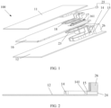
- FIG. 1 is a possible schematic structural diagram of an electronic device according to this embodiment of this application.
- the electronic device 100 provided in this embodiment of this application includes: a first bracket 11 and a second bracket 12 arranged opposite each other, as well as a circuit board 16, a loudspeaker unit 17, and an enclosing assembly 25 that are located between the first bracket 11 and the second bracket 12.
- the circuit board 16 has a first notch 161, and the loudspeaker unit 17 is arranged in the first notch 161.
- the enclosing assembly 25 is arranged around the first notch 161, and the enclosing assembly 25 is hermetically connected to the first bracket 11, the second bracket 12, and the circuit board 16.
- the first bracket 11, the second bracket 12, the circuit board 16, and the enclosing assembly enclose an acoustic chamber of the loudspeaker unit 17.
- the circuit board 16 may be a main circuit board in the electronic device, and the circuit board may be a printed circuit board or other possible circuit boards, which is not limited herein.
- the enclosing assembly forms a side wall of the acoustic chamber, and the first bracket and the second bracket form a top wall and a bottom wall of the acoustic chamber.
- the first bracket, the enclosing assembly, and the circuit board enclose a first accommodating chamber
- the second bracket, the enclosing assembly, and the circuit board enclose a second accommodating chamber.
- the first notch on the circuit board allows the first accommodating chamber to communicate with the second accommodating chamber.
- an axis of a sound outlet hole of the loudspeaker unit is parallel to the circuit board.
- the solution of this embodiment of this application in which the circuit board is provided with a first notch allows the loudspeaker unit to be arranged close to an edge of the circuit board because a narrow pressing edge on the circuit board is removed. This can shorten the length of the sound outlet hole of the loudspeaker unit, which is also known as the length of a sound outlet channel.
- the loudspeaker unit may be arranged on the first bracket, or the loudspeaker unit may be arranged on the second bracket.
- a volume of the acoustic chamber of the loudspeaker unit and a length of the sound outlet channel are the main factors affecting an external sound output effect of the loudspeaker unit.
- a larger volume of the acoustic chamber indicates a shorter sound outlet channel and better electroacoustic performance.
- the enclosing assembly 25 may include: a first enclosing plate 13, a second enclosing plate 14, and a transition leg 15.
- the first enclosing plate 13 is arranged between the first bracket 11 and the circuit board 16, and two ends of the first enclosing plate 13 are hermetically connected to the first bracket 11 and the circuit board 16.
- the second enclosing plate 14 is arranged between the second bracket 12 and the circuit board 16, and two ends of the second enclosing plate 14 are hermetically connected to the second bracket 12 and the circuit board 16.
- the first enclosing plate 13 and the second enclosing plate 14 each have a side opening facing a same direction as the first notch 161.
- a side portion of the transition leg 15 is hermetically connected to the side opening of the first enclosing plate 13, the side opening of the second enclosing plate 14, and the circuit board 16, and two ends of the transition leg 15 are hermetically connected to the first bracket 11 and the second bracket 12.
- the first notch 161 is located at inner sides of projection regions of the first enclosing plate 13 and the second enclosing plate 14 on the circuit board 16.
- the projection regions of the first enclosing plate and the second enclosing plate on the circuit board may be in any possible shape such as a "U" shape or a major arc shape (that is, an arc with a radian greater than 180°).
- the shapes of the projection regions of the first enclosing plate and the second enclosing plate on the circuit board may be the same as the shape of the first notch.
- the first notch is located at inner sides of projection regions of the first enclosing plate and the second enclosing plate on the circuit board" can ensure that the first notch can achieve communication between the first accommodating chamber and the second accommodating chamber.
- the transition leg is hermetically connected to the side opening of the first enclosing plate and the side opening of the second enclosing plate
- the side portion of the transition leg is hermetically connected to an outer wall at the side opening of the first enclosing plate and an outer wall at the side opening of the first enclosing plate.
- the transition leg 15 is integrally formed with the outer wall at the side opening 141 of the second enclosing plate 14.
- the second enclosing plate 14, the transition leg 15, and the second bracket 12 may be integrally formed.
- the transition leg extends beyond the second enclosing plate.
- the height of the transition leg is greater than the height of the second enclosing plate.
- first enclosing plate and the first bracket may be integrally formed.
- the height of the transition leg may be equal to a sum of the height of the first enclosing plate and the height of the second enclosing plate.
- the height of a component (for example, the transition leg) in the electronic device refers to a maximum dimension of the component in a direction of a connection line (for example, a perpendicular line) of the first bracket and the circuit board.
- the height of the loudspeaker unit is greater than the height of the first enclosing plate and the height of the second enclosing plate.
- the first enclosing plate and the second enclosing plate each have a side opening facing a same direction as the first notch, ensuring that the side portion of the transition leg can be hermetically connected to the circuit board (specifically a side wall of the circuit board).
- first enclosing plate and the second enclosing plate each have a side opening, and the side opening of the first enclosing plate and the side opening of the second enclosing plate face a same direction as the first notch and both face the transition leg, so that it is unnecessary to reserve a narrow pressing edge in a region of the circuit board close to the transition leg, providing assurance for providing the first notch on the circuit board.
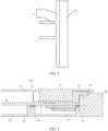
- FIG. 3(a) is a schematic layout diagram of a loudspeaker unit and a circuit board in the related art.
- the circuit board 16' in the related art is provided with a narrow pressing edge, so that a distance between the loudspeaker unit and the edge of the circuit board is at least greater than the width of the narrow pressing edge.
- FIG. 3(b) is a schematic layout diagram of the loudspeaker unit and the circuit board in this embodiment of this application. It can be seen that: 1.
- the electronic device may further include a frame.
- the first bracket, the second bracket, the circuit board, the loudspeaker unit, and the enclosing assembly are arranged in the frame.
- the transition leg 15 is arranged on the side wall 26 of the frame, and the acoustic chamber is enclosed by the first bracket 11, the second bracket 12, the circuit board 13, the enclosing assembly 25, and the side wall 26 of the frame.
- the transition leg when the transition leg is arranged on the side wall of the frame, the transition leg may include only two extension portions arranged opposite each other, and the two extension portions are directly arranged on the side wall of the frame.
- the first bracket, the second bracket, the circuit board, the enclosing assembly, and the side wall of the frame enclose the acoustic chamber of the loudspeaker unit. Therefore, there is no need to arrange the upright plate, ensuring that the loudspeaker unit can be arranged as close to the frame as possible, thereby further shortening the size of the sound outlet channel of the loudspeaker unit.
- a surface of the side wall of the frame close to the enclosing assembly may be subjected to a recessing treatment to facilitate a hermetical connection between the recessed portion and the first bracket.
- transition leg and the frame may be integrally formed.
- transition leg, the second enclosing plate, and the frame may be integrally formed.
- the acoustic chamber is enclosed by the first bracket, the second bracket, the circuit board, the enclosing assembly, and the side wall of the frame, ensuring that the loudspeaker unit can be in direct contact with the side wall of the frame, thereby minimizing the size of the sound outlet channel of the loudspeaker unit.
- the sound outlet hole 24 of the loudspeaker unit is arranged on the side wall 26 of the frame, and the sound outlet hole 24 is parallel to the circuit board 16.
- the electronic device 10 may further include a first sealing structure 18, where the first sealing structure 18 is stepped.
- the first sealing structure 18 may include a first sub-sealing ring, a second sub-sealing ring, and two first climbing arms.
- the first sub-sealing ring and the second sub-sealing ring have opposite openings, and two ends of each of the first climbing arms are respectively connected to the first sub-sealing ring and the second sub-sealing ring.
- the first sub-sealing ring is arranged between one end of the transition leg 15 and the first bracket 11; the two first climbing arms are arranged between the side portion of the transition leg 15 and the first enclosing plate 13; and the second sub-sealing ring is arranged between the first enclosing plate 13 and the circuit board 16.
- the two first climbing arms do not intersect, so that the first sub-sealing ring, the second sub-sealing ring, and the two first climbing arms form a stepped sealing ring.
- the two first climbing arms are arranged between the side portion of the transition leg and the first enclosing plate
- the two first climbing arms are arranged between the side portion of the transition leg and an outer wall at the side opening of the first enclosing plate.
- the first climbing arm is perpendicular to the first sub-sealing ring and the second sub-sealing ring.
- the size of the second sub-sealing ring matches the size of the projection region of the first enclosing plate on the circuit board.
- the first sealing structure may be made of sealing foam or silicone.
- a surface of the first sealing structure 18 facing away from the first bracket 11 is provided with a sealing rib 201. This can prevent eccentric errors generated during assembly of the first sealing structure and the second sealing structure, thereby further improving the sealing performance for the acoustic chamber in the electronic device.
- sealing between the first enclosing plate and the transition leg as well as sealing between the transition leg and the first bracket can be simultaneously implemented by using one sealing structure, thereby reducing sealing errors and improving the sealing performance.
- the electronic device 10 may further include a target sealing ring 23 matching the projection region of the second enclosing plate 14 on the circuit board 16.
- the target sealing ring 23 is arranged between a top surface of the second enclosing plate 14 and a bottom surface of the circuit board 16, achieving sealing between the second enclosing plate 14 and the circuit board 16.
- the target sealing ring has an opening, and the opening matches the side opening of the second enclosing plate. Specifically, the orientation and size of the opening of the target sealing ring are the same as those of the side opening of the second enclosing plate.
- the target sealing ring may be made of sealing foam or silicone.
- a first gap 19 may be present between the circuit board 16 and the transition leg 15.
- two possible implementation methods (which are, one possible implementation method and another possible implementation method described below) may be used to seal the first gap.
- the electronic device may further include a second sealing structure.
- the second sealing structure seals the first gap between the circuit board and the transition leg.
- the second sealing structure is described in detail below.
- the second sealing structure 20 may include a first support arm and a second support arm intersecting with each other.
- the first support arm is arranged on a surface of the circuit board 16 facing the second enclosing plate 14, and the second support arm is arranged between the circuit board 16 and the side portion of the transition leg 15 as well as between the first climbing arm and the side portion of the transition leg 15, so as to seal the first gap 19.
- the second sealing structure can not only seal the first gap between the circuit board and the transition leg but also improve sealing reliability because the first support arm is attached to the surface of the circuit board facing the second enclosing plate.
- first support arm and the second support arm are connected, and the first support arm and the second support arm form an included angle, for example, 90°.
- first support arm and the second support arm are L-shaped. It can be understood that the second sealing structure with the first support arm and the second support arm may also be referred to as an L-shaped sealing bracket.
- a portion of the second support arm is located between the circuit board and the side portion of the transition leg, and another portion of the second support arm is located between the first climbing arm and the transition leg.
- the first support arm may be specifically arranged between the target sealing ring and the circuit board.
- the second support arm is in interference fit with the first climbing arm. This can avoid the presence of a gap between the first sealing structure and the second sealing structure, thereby increasing the sealing performance for the acoustic chamber.
- the first support arm can be attached to the bottom surface of the circuit board, and the first support arm fills the first gap between the circuit board and the side portion of the transition leg. Therefore, the circuit board and the side portion of the transition leg can be sealed, and the connection strength of the second sealing structure can be enhanced, improving the sealing reliability.
- the second sealing structure 2020 may include a third support arm and a fourth support arm arranged opposite each other, and a connecting arm arranged between the third support arm and the fourth support arm.
- the third support arm and the fourth support arm are respectively arranged on opposite surfaces of the circuit board 16, and the connecting arm is arranged between the circuit board 16 and the transition leg 15.
- the third support arm is arranged on the surface of the circuit board facing the first enclosing plate
- the second support arm is arranged on the surface of the circuit board facing the second enclosing plate
- the connecting arm is arranged in the first gap (that is, the connecting arm fills the first gap).
- the third support arm may be arranged between the second sub-sealing ring and the circuit board, and is in interference fit with the second sub-sealing ring; and the fourth support arm may be arranged between the circuit board and the second enclosing plate, and is in interference fit with the target sealing ring.
- the third support arm and the fourth support arm of the second sealing structure are respectively attached to the two opposite surfaces of the circuit board, and the connecting arm of the second sealing structure fills the first gap between the circuit board and the transition leg. Therefore, the sealing reliability between the circuit board and the transition leg can be improved.
- two second sealing structures are provided in both the above method 1 and method 2, and the two first sealing structures are arranged corresponding to two sides of the first notch, for example, the two second sealing structures are both arranged in a region of the circuit board adjacent to the first notch.
- a gap may be present between the first sealing structure and the second sealing structure.
- a gap may be present in a corner between the first sealing structure 18 and the second sealing structure 20, that is, between the second support arm and the first climbing arm, and specifically in a region indicated by dashed box A in FIG. 7 .
- a gap may be in a corner between the first sealing structure 18 and the second sealing structure 20, that is, between the third support arm and the first climbing arm, and specifically in a region indicated by dashed box B in FIG. 9 .
- the electronic device provided in this embodiment of this application may further include a first adhesive member.
- the first adhesive member fills the gap between the first sealing structure and the second sealing structure.
- glue may be dispensed on a region indicated by an arrow in FIG. 10 between the first sealing structure 18 and the second sealing structure 20.
- the first adhesive member may be glue.
- glue can be dispensed in the gap between the first sealing structure and the second sealing structure, so as to seal the gap between the first sealing structure and the second sealing structure.
- the sealing performance for the acoustic chamber of the loudspeaker can be further improved.
- the second sealing structure 20 may include a second adhesive member, where the second adhesive member fills the first gap 19 between the circuit board 16 and the transition leg 15 as shown in FIG. 5 .
- the first adhesive member may be glue.
- glue can be directly dispensed in the gap between the circuit board and the transition leg, so as to seal the circuit board and the transition leg.
- the sealing performance for the acoustic chamber in the electronic device can be improved, and the assembly difficulty of the electronic device can be reduced.
- the electronic device 10 may further include a third sealing structure 22, where the third sealing structure 22 is stepped.
- the third sealing structure 22 may include a third sub-sealing ring, a fourth sub-sealing ring, and two second climbing arms arranged between the third sub-sealing ring and the fourth sub-sealing ring.
- the third sub-sealing ring and the fourth sub-sealing ring have opposite openings, and two ends of each of the second climbing arms are respectively connected to the third sub-sealing ring and the fourth sub-sealing ring.
- the third sub-sealing ring is arranged between one end of the transition leg 15 and the first sub-sealing ring, and the third sub-sealing ring is in interference fit with the first sub-sealing ring; the fourth sub-sealing ring is arranged between the second enclosing plate 14 and the circuit board 16; the two second climbing arms are arranged between the side portion of the transition leg 15 and the circuit board 16 as well as between the side portion of the transition leg 15 and the first climbing arm; and the second climbing arm is in interference fit with the first climbing arm.
- the fourth sub-sealing ring is equivalent to the target sealing ring in the above embodiment.
- two second climbing arms are respectively arranged at an opening of the fourth sub-sealing ring, and the two second climbing arms are connected to the third sub-sealing ring to form the third sealing structure.
- a surface of the third sealing structure facing the first bracket may be provided with a sealing rib. This can prevent eccentric errors generated during assembly of the first sealing structure and the second sealing structure, thereby further improving the sealing performance for the acoustic chamber in the electronic device.
- sealing ribs on the third sealing structure and the first sealing structure can be staggered to facilitate the engagement of the first sealing structure and the third sealing structure through their respective sealing ribs.
- the third sealing structure can seal the first gap between the circuit board and the side portion of the transition leg while sealing the second enclosing plate and the circuit board. Therefore, another possible implementation method can reduce the number of the sealing structures, thereby avoiding the introduction of new installation errors (for example, a gap between the first sealing structure and the second structure).
- the loudspeaker unit 17 is moved up to get close to a side of the frame (that is, a side wall), a narrow pressing edge at a corresponding position of the PCB (that is, the circuit board 16) is removed, and the side wall 26 of the frame serves as the transition leg 15 to extend into the notch of the PCB.
- the first sealing structure 18 is made of a silicone material, the first sub-sealing ring in the first sealing structure 18 is in pressing fit with the transition leg 15, and the second sub-sealing ring is in pressing fit with the PCB.
- L-shaped silicone that is, the second sealing structure 20
- one side of the L-shaped silicone is adhered to the back of the PCB, and the other side is upward adhered along a side surface (that is, the side portion) of the transition leg 15 (actually, it can be upward adhered along the first climbing arm), filling the gap between the transition leg 15 and the PCB.
- a corner between the first sealing structure 18 and the second sealing structure 20 is sealed by dispensing glue, thereby ensuring a good sealing effect.
- the loudspeaker unit 17 is moved up to get close to a side of the frame (that is, a side wall), a narrow pressing edge at a corresponding position of the PCB (that is, the circuit board 16) is removed, and the side wall 26 of the frame serves as the transition leg 15 to extend into the notch of the PCB.
- the first sealing structure 18 is made of a silicone material, the first sub-sealing ring in the first sealing structure 18 is in pressing fit with the transition leg 15, and the second sub-sealing ring is in pressing fit with the PCB.
- a U-shaped silicone clip (that is, the second sealing structure 20) is adhered to a step position (that is, the first gap 19) between the first sealing structure 18 and the PCB, two long sides (that are, the third support arm and the fourth support arm) of the U-shaped silicone clip are respectively adhered to both sides of the PCB, and a side (that is, the connecting arm) of the U-shaped silicone clip is used for filling a gap at a step position between the transition leg 15 and the PCB. Then, a corner between the first sealing structure 18 and the U-shaped silicone clip is sealed by dispensing glue, thereby ensuring a good sealing effect for the acoustic chamber.
- the loudspeaker unit 17 is moved up to get close to a side of the frame (that is, a side wall), a narrow pressing edge at a corresponding position of the PCB (that is, the circuit board 16) is removed, and the side wall 26 of the frame serves as the transition leg 15 to extend into the notch of the PCB.
- the first sealing structure 18 is made of a silicone material, the first sub-sealing ring in the first sealing structure 18 is in pressing fit with the transition leg 15, the second sub-sealing ring is in pressing fit with the PCB, and a step position (that is, the first gap 19) between the transition leg 15 and the PCB is sealed by dispensing glue.
- the loudspeaker unit 17 can move toward the frame, shortening the sound outlet channel and optimizing the PCB layout.
- the gap at the step position that is originally difficult to seal through interference fit can be filled with glue to ensure the airtightness of the entire upward chamber, while non-step positions are in interference fit with the silicon gasket to achieve a good sealing effect.
- the loudspeaker unit 17 is moved up to get close to a side of the frame (that is, a side wall), a narrow pressing edge at a corresponding position of the PCB (that is, the circuit board 16) is removed, and the side wall 26 of the frame serves as the transition leg 15 to extend into the notch of the PCB.
- the first sealing structure 18 is made of a silicone material, the first sub-sealing ring in the first sealing structure 18 is pressed between the transition leg 15 and the first bracket 11, and the second sub-sealing ring is pressed between the PCB and the first enclosing plate 13.
- the sealing foam (that is, the target sealing ring 23) between the second bracket and the second enclosing plate 14 is replaced with a stepped third sealing structure 22, where the lower half portion of the third sealing structure 22 (that is, the fourth sub-sealing ring) is laid between the second enclosing plate 14 and the PCB, and the upper half portion of the third sealing structure 22 (that is, the third sub-sealing ring) is laid at a step position of the transition leg 15.
- the third sub-sealing ring is arranged between one end of the transition leg 15 and the first sub-sealing ring, and the third sub-sealing ring is in interference fit with the first sub-sealing ring.
- a surface of the first sealing structure 18 facing away from the first bracket 11 is provided with a sealing rib 201.
- the step position between the transition leg 15 and the PCB is sealed through the interference fit between the first sealing structure 18 made of a silicone material and the third sealing structure 22 made of a sealing foam material.
- the first sealing structure 18 and the third sealing structure 22 are both soft structures, which can ensure the fitting and sealing at the step position and the corner of the transition leg 15.
- the sealing rib on the first sealing structure 18 can avoid poor sealing caused by eccentric errors generated during assembly of the first sealing structure 18 and the third sealing structure 22.
- the electronic device in this embodiment of this application may be a mobile electronic device or a non-mobile electronic device.
- the mobile electronic device may be a mobile phone, a tablet computer, a notebook computer, a palmtop computer, a vehicle-mounted electronic device, a wearable device, an ultra-mobile personal computer (ultra-mobile personal computer, UMPC), a netbook, a personal digital assistant (personal digital assistant, PDA), or the like;
- the non-mobile electronic device may be a personal computer (personal computer, PC), a television (television, TV), a smart speaker, a teller machine, a self-service machine, or the like. This is not specifically limited in the embodiments of the present invention.
- the technical solutions of the present invention essentially or the part contributing to the prior art may be implemented in a form of a software product.
- the software product is stored in a storage medium (such as a ROM/RAM, a magnetic disk, or an optical disc), and includes several instructions for instructing a terminal (which may be a mobile phone, a computer, a server, an air conditioner, a network device, or the like) to perform the methods described in the embodiments of this disclosure.
Landscapes
- Physics & Mathematics (AREA)
- Engineering & Computer Science (AREA)
- Acoustics & Sound (AREA)
- Signal Processing (AREA)
- Details Of Audible-Bandwidth Transducers (AREA)
- Casings For Electric Apparatus (AREA)
Abstract
Description
- This application claims priority to
Chinese Patent Application No. 202210589390.5, filed in China on May 26, 2022 - This application pertains to the field of battery technologies, and specifically relates to an electronic device.
- Currently, a loudspeaker unit of an electronic device, for example, an acoustic chamber of an upper loudspeaker unit, can be enclosed by a circuit board such as a printed circuit board PCB (Printed Circuit Board, PCB) and two circuit board cover plates arranged on two sides of the circuit board.
- Specifically, a region of the circuit board facing the loudspeaker unit is provided with a through hole for the loudspeaker unit to pass through, and each of the two circuit board cover plates and the circuit board are sealed through pressing by using sealing foam, so that the circuit board and the two circuit board cover plates arranged on the two sides of the circuit board enclose the acoustic chamber of the loudspeaker unit.
- As such, since each of the two circuit board cover plates and the PCB are sealed through pressing by using the sealing foam, a sound outlet channel of the loudspeaker unit is relatively long, leading to poor electroacoustic performance of the loudspeaker unit in the electronic device.
- Embodiments of this application are intended to provide an electronic device, which can resolve the problem of poor electroacoustic performance of loudspeaker units in electronic devices due to long sound outlet channels of the loudspeaker units.
- An embodiment of this application provides an electronic device including: a first bracket and a second bracket arranged opposite each other, as well as a circuit board, a loudspeaker unit, and an enclosing assembly that are located between the first bracket and the second bracket. The circuit board has a first notch, and the loudspeaker unit is arranged in the first notch. The enclosing assembly is arranged around the first notch, and the enclosing assembly is hermetically connected to the first bracket, the second bracket, and the circuit board. The first bracket, the second bracket, the circuit board, and the enclosing assembly enclose an acoustic chamber of the loudspeaker unit.
- In this embodiment of this application, the circuit board is provided with the first notch, and the loudspeaker unit is arranged in the first notch, so that a loudspeaker is close to an edge of the circuit board, thereby shortening a sound outlet channel of the loudspeaker unit. This can improve the electroacoustic performance of the loudspeaker unit in the electronic device.
-
-
FIG. 1 is a first schematic structural diagram of an electronic device according to an embodiment of this application; -
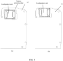
FIG. 2 is a schematic structural diagram of a sound outlet hole in an electronic device according to an embodiment of this application; -
FIG. 3 is a schematic diagram of comparison between a circuit board in an electronic device according to an embodiment of this application and a circuit board in the prior art; -
FIG. 4 is a second schematic structural diagram of an electronic device according to an embodiment of this application; -
FIG. 5 is a third schematic structural diagram of an electronic device according to an embodiment of this application; -
FIG. 6 is a fourth schematic structural diagram of an electronic device according to an embodiment of this application; -
FIG. 7 is a fifth schematic structural diagram of an electronic device according to an embodiment of this application; -
FIG. 8 is a sixth schematic structural diagram of an electronic device according to an embodiment of this application; -
FIG. 9 is a seventh schematic structural diagram of an electronic device according to an embodiment of this application; -
FIG. 10 is an eighth schematic structural diagram of an electronic device according to an embodiment of this application; -
FIG. 11 is a ninth schematic structural diagram of an electronic device according to an embodiment of this application; -
FIG. 12 is a tenth schematic structural diagram of an electronic device according to an embodiment of this application; and -
FIG. 13 is a schematic diagram of a first sealing structure in an electronic device according to an embodiment of this application. - Reference signs in
FIG. 1 to FIG. 13 are as follows:
10. electronic device; 11. first bracket; 12. second bracket; 13. first enclosing plate; 14. second enclosing plate; 141. side opening of second enclosing plate; 15. transition leg; 151. extension portion; 152. upright plate; 16. circuit board; 161. first notch; 17. loudspeaker unit; 18. first sealing structure; 19. first gap; 20. second sealing structure; 201. sealing rib; 22. third sealing structure; 23. target sealing ring; 24. sound outlet hole; 25. enclosing assembly; and 26. side wall of frame. - The following clearly describes the technical solutions in the embodiments of this application with reference to the accompanying drawings in the embodiments of this application. Apparently, the described embodiments are merely some rather than all of the embodiments of this application. All other embodiments obtained by persons of ordinary skill in the art based on the embodiments of this application shall fall within the protection scope of this application.
- The terms "first", "second", and the like in this specification and claims of this application are used to distinguish between similar objects rather than to indicate a specific order or sequence. It should be understood that data used in this way is used interchangeably in appropriate circumstances so that the embodiments of this application can be implemented in other orders than the order illustrated or described herein. In addition, "first", "second", and the like are usually used to distinguish objects of a same type, and do not restrict a quantity of objects. For example, there may be one or a plurality of first objects. In addition, "and/or" in the specification and claims represents at least one of connected objects, and the character "/" generally indicates that the contextually associated objects have an "or" relationship.
- The following describes in detail an electronic device provided in the embodiments of this application by using specific embodiments and application scenarios thereof with reference to the accompanying drawings.
- An embodiment of this application provides an electronic device.
FIG. 1 is a possible schematic structural diagram of an electronic device according to this embodiment of this application. As shown inFIG. 1 , theelectronic device 100 provided in this embodiment of this application includes: afirst bracket 11 and asecond bracket 12 arranged opposite each other, as well as acircuit board 16, aloudspeaker unit 17, and an enclosingassembly 25 that are located between thefirst bracket 11 and thesecond bracket 12. Thecircuit board 16 has afirst notch 161, and theloudspeaker unit 17 is arranged in thefirst notch 161. The enclosingassembly 25 is arranged around thefirst notch 161, and the enclosingassembly 25 is hermetically connected to thefirst bracket 11, thesecond bracket 12, and thecircuit board 16. Thefirst bracket 11, thesecond bracket 12, thecircuit board 16, and the enclosing assembly enclose an acoustic chamber of theloudspeaker unit 17. - Optionally, as shown in
FIG. 1 , thecircuit board 16 may be a main circuit board in the electronic device, and the circuit board may be a printed circuit board or other possible circuit boards, which is not limited herein. - In this embodiment of this application, the enclosing assembly forms a side wall of the acoustic chamber, and the first bracket and the second bracket form a top wall and a bottom wall of the acoustic chamber.
- The first bracket, the enclosing assembly, and the circuit board enclose a first accommodating chamber, and the second bracket, the enclosing assembly, and the circuit board enclose a second accommodating chamber. The first notch on the circuit board allows the first accommodating chamber to communicate with the second accommodating chamber.
- It should be noted that an axis of a sound outlet hole of the loudspeaker unit is parallel to the circuit board.
- In this embodiment of this application, compared with a solution of the related art in which the circuit board is provided with a through hole, the solution of this embodiment of this application in which the circuit board is provided with a first notch allows the loudspeaker unit to be arranged close to an edge of the circuit board because a narrow pressing edge on the circuit board is removed. This can shorten the length of the sound outlet hole of the loudspeaker unit, which is also known as the length of a sound outlet channel.
- Optionally, the loudspeaker unit may be arranged on the first bracket, or the loudspeaker unit may be arranged on the second bracket.
- It should be noted that for the loudspeaker unit, in a case that the loudspeaker unit has no change, a volume of the acoustic chamber of the loudspeaker unit and a length of the sound outlet channel are the main factors affecting an external sound output effect of the loudspeaker unit. A larger volume of the acoustic chamber indicates a shorter sound outlet channel and better electroacoustic performance.
- Optionally, as shown in
FIG. 1 , the enclosingassembly 25 may include: afirst enclosing plate 13, asecond enclosing plate 14, and atransition leg 15. - The
first enclosing plate 13 is arranged between thefirst bracket 11 and thecircuit board 16, and two ends of thefirst enclosing plate 13 are hermetically connected to thefirst bracket 11 and thecircuit board 16. Thesecond enclosing plate 14 is arranged between thesecond bracket 12 and thecircuit board 16, and two ends of thesecond enclosing plate 14 are hermetically connected to thesecond bracket 12 and thecircuit board 16. Thefirst enclosing plate 13 and thesecond enclosing plate 14 each have a side opening facing a same direction as thefirst notch 161. A side portion of thetransition leg 15 is hermetically connected to the side opening of thefirst enclosing plate 13, the side opening of thesecond enclosing plate 14, and thecircuit board 16, and two ends of thetransition leg 15 are hermetically connected to thefirst bracket 11 and thesecond bracket 12. - The
first notch 161 is located at inner sides of projection regions of thefirst enclosing plate 13 and thesecond enclosing plate 14 on thecircuit board 16. - It can be understood that in this embodiment of this application, the projection regions of the first enclosing plate and the second enclosing plate on the circuit board may be in any possible shape such as a "U" shape or a major arc shape (that is, an arc with a radian greater than 180°).
- In a practical implementation, the shapes of the projection regions of the first enclosing plate and the second enclosing plate on the circuit board may be the same as the shape of the first notch.
- In this embodiment of this application, "the first notch is located at inner sides of projection regions of the first enclosing plate and the second enclosing plate on the circuit board" can ensure that the first notch can achieve communication between the first accommodating chamber and the second accommodating chamber.
- In this embodiment of this application, "the transition leg is hermetically connected to the side opening of the first enclosing plate and the side opening of the second enclosing plate" can be understood as that the side portion of the transition leg is hermetically connected to an outer wall at the side opening of the first enclosing plate and an outer wall at the side opening of the first enclosing plate.
- For example, as shown in
FIG. 2 , thetransition leg 15 is integrally formed with the outer wall at theside opening 141 of thesecond enclosing plate 14. - Optionally, as shown in
FIG. 2 , thesecond enclosing plate 14, thetransition leg 15, and thesecond bracket 12 may be integrally formed. - In this embodiment of this application, the transition leg extends beyond the second enclosing plate. To be specific, the height of the transition leg is greater than the height of the second enclosing plate.
- Optionally, the first enclosing plate and the first bracket may be integrally formed.
- Optionally, the height of the transition leg may be equal to a sum of the height of the first enclosing plate and the height of the second enclosing plate.
- It should be noted that in this embodiment of this application, the height of a component (for example, the transition leg) in the electronic device refers to a maximum dimension of the component in a direction of a connection line (for example, a perpendicular line) of the first bracket and the circuit board.
- In this embodiment of this application, the height of the loudspeaker unit is greater than the height of the first enclosing plate and the height of the second enclosing plate.
- In this embodiment of this application, the first enclosing plate and the second enclosing plate each have a side opening facing a same direction as the first notch, ensuring that the side portion of the transition leg can be hermetically connected to the circuit board (specifically a side wall of the circuit board).
- In addition, the first enclosing plate and the second enclosing plate each have a side opening, and the side opening of the first enclosing plate and the side opening of the second enclosing plate face a same direction as the first notch and both face the transition leg, so that it is unnecessary to reserve a narrow pressing edge in a region of the circuit board close to the transition leg, providing assurance for providing the first notch on the circuit board.
- It can be understood that in this embodiment of this application, as shown in
FIG. 3, FIG. 3(a) is a schematic layout diagram of a loudspeaker unit and a circuit board in the related art. As shown inFIG. 3(a) , the circuit board 16' in the related art is provided with a narrow pressing edge, so that a distance between the loudspeaker unit and the edge of the circuit board is at least greater than the width of the narrow pressing edge.FIG. 3(b) is a schematic layout diagram of the loudspeaker unit and the circuit board in this embodiment of this application. It can be seen that: 1. The loudspeaker unit in the electronic device provided in this embodiment of this application can be arranged closer to the edge of thecircuit board 16, thereby shortening the length of the sound outlet channel of the loudspeaker unit. 2. In the related art, a layout space close to the narrow pressing edge of the circuit board has low utilization due to its small size, leading to a demand for an increased effective layout area on the circuit board in the related art in a case that the layout requirements remain unchanged, thus facilitating a thin and light design of the entire electronic device. In this embodiment of this application, since it is unnecessary to reserve a narrow pressing edge on the circuit board, a larger layout space is provided for a portion of the circuit board away from the first notch, optimizing the layout of electronic components on the circuit board and facilitating the thin and light design of the entire electronic device. - Optionally,
FIG. 4 is a possible schematic structural diagram of thetransition leg 15. As shown inFIG. 4 , thetransition leg 15 includes twoextension portions 151 arranged opposite each other, and anupright plate 152 arranged between the twoextension portions 151 and perpendicular to the twoextension portions 151. A side portion of thetransition leg 15 is formed by the twoextension portions 151. The transition leg including theupright plate 152 can ensure that the first bracket, the second bracket, the circuit board, and the enclosing assembly can enclose a sealed chamber (that is, the acoustic chamber). - Optionally, the side portion of the transition leg extends into the
first notch 161 and is hermetically connected to thecircuit board 16. - It can be understood that in this embodiment of this application, the side portion of the transition leg is specifically hermetically connected to a side wall of the circuit board corresponding to the first notch.
- In this embodiment of this application, since the side portion of the transition leg extends into the first notch and is hermetically connected to the circuit board, a contact area between the transition leg and the circuit board can be increased, thereby improving the sealing reliability.
- In the electronic device provided in this embodiment of this application, the circuit board is provided with the first notch, and the loudspeaker unit is arranged in the first notch, so that the loudspeaker unit is close to the edge of the circuit board, thereby shortening the sound outlet channel of the loudspeaker unit. This can improve the electroacoustic performance of the loudspeaker unit in the electronic device.
- Optionally, the electronic device may further include a frame. The first bracket, the second bracket, the circuit board, the loudspeaker unit, and the enclosing assembly are arranged in the frame. As shown in
FIG. 1 , thetransition leg 15 is arranged on theside wall 26 of the frame, and the acoustic chamber is enclosed by thefirst bracket 11, thesecond bracket 12, thecircuit board 13, the enclosingassembly 25, and theside wall 26 of the frame. - Specifically, when the transition leg is arranged on the side wall of the frame, the transition leg may include only two extension portions arranged opposite each other, and the two extension portions are directly arranged on the side wall of the frame. In this way, the first bracket, the second bracket, the circuit board, the enclosing assembly, and the side wall of the frame enclose the acoustic chamber of the loudspeaker unit. Therefore, there is no need to arrange the upright plate, ensuring that the loudspeaker unit can be arranged as close to the frame as possible, thereby further shortening the size of the sound outlet channel of the loudspeaker unit.
- Further optionally, a surface of the side wall of the frame close to the enclosing assembly may be subjected to a recessing treatment to facilitate a hermetical connection between the recessed portion and the first bracket.
- Optionally, the transition leg and the frame may be integrally formed. Alternatively, the transition leg, the second enclosing plate, and the frame may be integrally formed.
- In this embodiment of this application, the acoustic chamber is enclosed by the first bracket, the second bracket, the circuit board, the enclosing assembly, and the side wall of the frame, ensuring that the loudspeaker unit can be in direct contact with the side wall of the frame, thereby minimizing the size of the sound outlet channel of the loudspeaker unit.
- Optionally, as shown in
FIG. 2 , thesound outlet hole 24 of the loudspeaker unit is arranged on theside wall 26 of the frame, and thesound outlet hole 24 is parallel to thecircuit board 16. - Optionally, as shown in
FIG. 1 ,FIG. 5 ,FIG. 6 to FIG. 9 ,FIG. 11 , andFIG. 12 , theelectronic device 10 may further include afirst sealing structure 18, where thefirst sealing structure 18 is stepped. Thefirst sealing structure 18 may include a first sub-sealing ring, a second sub-sealing ring, and two first climbing arms. The first sub-sealing ring and the second sub-sealing ring have opposite openings, and two ends of each of the first climbing arms are respectively connected to the first sub-sealing ring and the second sub-sealing ring. - The first sub-sealing ring is arranged between one end of the
transition leg 15 and thefirst bracket 11; the two first climbing arms are arranged between the side portion of thetransition leg 15 and thefirst enclosing plate 13; and the second sub-sealing ring is arranged between thefirst enclosing plate 13 and thecircuit board 16. - It can be understood that in this embodiment of this application, the two first climbing arms do not intersect, so that the first sub-sealing ring, the second sub-sealing ring, and the two first climbing arms form a stepped sealing ring.
- In this embodiment of this application, "the two first climbing arms are arranged between the side portion of the transition leg and the first enclosing plate" can be understood as that the two first climbing arms are arranged between the side portion of the transition leg and an outer wall at the side opening of the first enclosing plate.
- In this embodiment of this application, the first climbing arm is perpendicular to the first sub-sealing ring and the second sub-sealing ring.
- It can be understood that in this embodiment of this application, the size of the second sub-sealing ring matches the size of the projection region of the first enclosing plate on the circuit board.
- Optionally, the first sealing structure may be made of sealing foam or silicone.
- Optionally, as shown in
FIG. 13 , a surface of thefirst sealing structure 18 facing away from thefirst bracket 11 is provided with a sealingrib 201. This can prevent eccentric errors generated during assembly of the first sealing structure and the second sealing structure, thereby further improving the sealing performance for the acoustic chamber in the electronic device. - In this embodiment of this application, since the first sealing structure is stepped, sealing between the first enclosing plate and the transition leg as well as sealing between the transition leg and the first bracket can be simultaneously implemented by using one sealing structure, thereby reducing sealing errors and improving the sealing performance.
- Optionally, as shown in
FIG. 1 andFIG. 5 toFIG. 9 , theelectronic device 10 may further include atarget sealing ring 23 matching the projection region of thesecond enclosing plate 14 on thecircuit board 16. Thetarget sealing ring 23 is arranged between a top surface of thesecond enclosing plate 14 and a bottom surface of thecircuit board 16, achieving sealing between thesecond enclosing plate 14 and thecircuit board 16. - It can be seen that the target sealing ring has an opening, and the opening matches the side opening of the second enclosing plate. Specifically, the orientation and size of the opening of the target sealing ring are the same as those of the side opening of the second enclosing plate.
- Optionally, the target sealing ring may be made of sealing foam or silicone.
- Optionally, as shown in
FIG. 5 , when thefirst sealing structure 18 is used, afirst gap 19 may be present between thecircuit board 16 and thetransition leg 15. In this embodiment of this application, two possible implementation methods (which are, one possible implementation method and another possible implementation method described below) may be used to seal the first gap. - In a possible implementation method, the electronic device may further include a second sealing structure. The second sealing structure seals the first gap between the circuit board and the transition leg.
- The second sealing structure is described in detail below.
- Optionally, in
method 1, as shown inFIG. 6 and FIG. 7 , thesecond sealing structure 20 may include a first support arm and a second support arm intersecting with each other. The first support arm is arranged on a surface of thecircuit board 16 facing thesecond enclosing plate 14, and the second support arm is arranged between thecircuit board 16 and the side portion of thetransition leg 15 as well as between the first climbing arm and the side portion of thetransition leg 15, so as to seal thefirst gap 19. In this way, the second sealing structure can not only seal the first gap between the circuit board and the transition leg but also improve sealing reliability because the first support arm is attached to the surface of the circuit board facing the second enclosing plate. - Specifically, the first support arm and the second support arm are connected, and the first support arm and the second support arm form an included angle, for example, 90°.
- It can be seen that the first support arm and the second support arm are L-shaped. It can be understood that the second sealing structure with the first support arm and the second support arm may also be referred to as an L-shaped sealing bracket.
- It can be understood that in this embodiment of this application, a portion of the second support arm is located between the circuit board and the side portion of the transition leg, and another portion of the second support arm is located between the first climbing arm and the transition leg.
- Optionally, the first support arm may be specifically arranged between the target sealing ring and the circuit board.
- Optionally, the second support arm is in interference fit with the first climbing arm. This can avoid the presence of a gap between the first sealing structure and the second sealing structure, thereby increasing the sealing performance for the acoustic chamber.
- In this embodiment of this application, the first support arm can be attached to the bottom surface of the circuit board, and the first support arm fills the first gap between the circuit board and the side portion of the transition leg. Therefore, the circuit board and the side portion of the transition leg can be sealed, and the connection strength of the second sealing structure can be enhanced, improving the sealing reliability.
- Optionally, in method 2, as shown in
FIG. 8 and FIG. 9 , the second sealing structure 2020 may include a third support arm and a fourth support arm arranged opposite each other, and a connecting arm arranged between the third support arm and the fourth support arm. - The third support arm and the fourth support arm are respectively arranged on opposite surfaces of the
circuit board 16, and the connecting arm is arranged between thecircuit board 16 and thetransition leg 15. - Optionally, it is assumed that the third support arm is arranged on the surface of the circuit board facing the first enclosing plate, the second support arm is arranged on the surface of the circuit board facing the second enclosing plate, and the connecting arm is arranged in the first gap (that is, the connecting arm fills the first gap).
- It can be seen that the second sealing structure is clamped on the circuit board.
- It can be understood that in this embodiment of this application, the third support arm may be arranged between the second sub-sealing ring and the circuit board, and is in interference fit with the second sub-sealing ring; and the fourth support arm may be arranged between the circuit board and the second enclosing plate, and is in interference fit with the target sealing ring.
- In this embodiment of this application, the third support arm and the fourth support arm of the second sealing structure are respectively attached to the two opposite surfaces of the circuit board, and the connecting arm of the second sealing structure fills the first gap between the circuit board and the transition leg. Therefore, the sealing reliability between the circuit board and the transition leg can be improved.
- In this embodiment of this application, two second sealing structures are provided in both the
above method 1 and method 2, and the two first sealing structures are arranged corresponding to two sides of the first notch, for example, the two second sealing structures are both arranged in a region of the circuit board adjacent to the first notch. - In the
above method 1 and method 2, a gap may be present between the first sealing structure and the second sealing structure. - For example, as shown in
FIG. 7 , when thesecond sealing structure 20 includes a first support arm and a second support arm intersecting with each other, a gap may be present in a corner between thefirst sealing structure 18 and thesecond sealing structure 20, that is, between the second support arm and the first climbing arm, and specifically in a region indicated by dashed box A inFIG. 7 . - For another example, as shown in
FIG. 9 , when thesecond sealing structure 20 includes a third support arm, a fourth support arm, and a connecting arm, a gap may be in a corner between thefirst sealing structure 18 and thesecond sealing structure 20, that is, between the third support arm and the first climbing arm, and specifically in a region indicated by dashed box B inFIG. 9 . - To seal the gap between the first sealing structure and the second sealing structure, the electronic device provided in this embodiment of this application may further include a first adhesive member. The first adhesive member fills the gap between the first sealing structure and the second sealing structure.
- For example, as shown in
FIG. 10 , glue may be dispensed on a region indicated by an arrow inFIG. 10 between thefirst sealing structure 18 and thesecond sealing structure 20. - Optionally, the first adhesive member may be glue. To be specific, glue can be dispensed in the gap between the first sealing structure and the second sealing structure, so as to seal the gap between the first sealing structure and the second sealing structure.
- In this embodiment of this application, since the gap between the first sealing structure and the second sealing structure can be sealed by a first sealing member, the sealing performance for the acoustic chamber of the loudspeaker can be further improved.
- Optionally, in method 3, the
second sealing structure 20 may include a second adhesive member, where the second adhesive member fills thefirst gap 19 between thecircuit board 16 and thetransition leg 15 as shown inFIG. 5 . - Optionally, the first adhesive member may be glue. To be specific, glue can be directly dispensed in the gap between the circuit board and the transition leg, so as to seal the circuit board and the transition leg.
- In this embodiment of this application, since the gap between the circuit board and the transition leg can be adhered by the first adhesive member, the sealing performance for the acoustic chamber in the electronic device can be improved, and the assembly difficulty of the electronic device can be reduced.
- In another possible implementation method, as shown in
FIG. 12 , theelectronic device 10 may further include athird sealing structure 22, where thethird sealing structure 22 is stepped. Thethird sealing structure 22 may include a third sub-sealing ring, a fourth sub-sealing ring, and two second climbing arms arranged between the third sub-sealing ring and the fourth sub-sealing ring. - The third sub-sealing ring and the fourth sub-sealing ring have opposite openings, and two ends of each of the second climbing arms are respectively connected to the third sub-sealing ring and the fourth sub-sealing ring.
- The third sub-sealing ring is arranged between one end of the
transition leg 15 and the first sub-sealing ring, and the third sub-sealing ring is in interference fit with the first sub-sealing ring; the fourth sub-sealing ring is arranged between thesecond enclosing plate 14 and thecircuit board 16; the two second climbing arms are arranged between the side portion of thetransition leg 15 and thecircuit board 16 as well as between the side portion of thetransition leg 15 and the first climbing arm; and the second climbing arm is in interference fit with the first climbing arm. - It can be understood that in this embodiment of this application, the fourth sub-sealing ring is equivalent to the target sealing ring in the above embodiment. To be specific, in another possible implementation method, two second climbing arms are respectively arranged at an opening of the fourth sub-sealing ring, and the two second climbing arms are connected to the third sub-sealing ring to form the third sealing structure.
- Further optionally, a surface of the third sealing structure facing the first bracket may be provided with a sealing rib. This can prevent eccentric errors generated during assembly of the first sealing structure and the second sealing structure, thereby further improving the sealing performance for the acoustic chamber in the electronic device.
- It can be understood that the sealing ribs on the third sealing structure and the first sealing structure can be staggered to facilitate the engagement of the first sealing structure and the third sealing structure through their respective sealing ribs.
- For other descriptions of the third sealing structure, refer to the relevant descriptions in the foregoing embodiments.
- In this embodiment of this application, the third sealing structure can seal the first gap between the circuit board and the side portion of the transition leg while sealing the second enclosing plate and the circuit board. Therefore, another possible implementation method can reduce the number of the sealing structures, thereby avoiding the introduction of new installation errors (for example, a gap between the first sealing structure and the second structure).
- The following illustratively describes the electronic device provided in this embodiment of this application.
- In one possible implementation method, as shown in
FIG. 6 and FIG. 7 , theloudspeaker unit 17 is moved up to get close to a side of the frame (that is, a side wall), a narrow pressing edge at a corresponding position of the PCB (that is, the circuit board 16) is removed, and theside wall 26 of the frame serves as thetransition leg 15 to extend into the notch of the PCB. Thefirst sealing structure 18 is made of a silicone material, the first sub-sealing ring in thefirst sealing structure 18 is in pressing fit with thetransition leg 15, and the second sub-sealing ring is in pressing fit with the PCB. L-shaped silicone (that is, the second sealing structure 20) is adhered to a step position between thetransition leg 15 and the PCB, one side of the L-shaped silicone is adhered to the back of the PCB, and the other side is upward adhered along a side surface (that is, the side portion) of the transition leg 15 (actually, it can be upward adhered along the first climbing arm), filling the gap between thetransition leg 15 and the PCB. Then, a corner between thefirst sealing structure 18 and thesecond sealing structure 20 is sealed by dispensing glue, thereby ensuring a good sealing effect. - In one possible implementation method, as shown in
FIG. 8 and FIG. 9 , theloudspeaker unit 17 is moved up to get close to a side of the frame (that is, a side wall), a narrow pressing edge at a corresponding position of the PCB (that is, the circuit board 16) is removed, and theside wall 26 of the frame serves as thetransition leg 15 to extend into the notch of the PCB. Thefirst sealing structure 18 is made of a silicone material, the first sub-sealing ring in thefirst sealing structure 18 is in pressing fit with thetransition leg 15, and the second sub-sealing ring is in pressing fit with the PCB. A U-shaped silicone clip (that is, the second sealing structure 20) is adhered to a step position (that is, the first gap 19) between thefirst sealing structure 18 and the PCB, two long sides (that are, the third support arm and the fourth support arm) of the U-shaped silicone clip are respectively adhered to both sides of the PCB, and a side (that is, the connecting arm) of the U-shaped silicone clip is used for filling a gap at a step position between thetransition leg 15 and the PCB. Then, a corner between thefirst sealing structure 18 and the U-shaped silicone clip is sealed by dispensing glue, thereby ensuring a good sealing effect for the acoustic chamber. - In one possible implementation method, as shown in
FIG. 5 , theloudspeaker unit 17 is moved up to get close to a side of the frame (that is, a side wall), a narrow pressing edge at a corresponding position of the PCB (that is, the circuit board 16) is removed, and theside wall 26 of the frame serves as thetransition leg 15 to extend into the notch of the PCB. Thefirst sealing structure 18 is made of a silicone material, the first sub-sealing ring in thefirst sealing structure 18 is in pressing fit with thetransition leg 15, the second sub-sealing ring is in pressing fit with the PCB, and a step position (that is, the first gap 19) between thetransition leg 15 and the PCB is sealed by dispensing glue. Since the narrow pressing edge on the PCB is removed, theloudspeaker unit 17 can move toward the frame, shortening the sound outlet channel and optimizing the PCB layout. In addition, due to the adaptability of a silicone gasket (that is, the first sealing structure 18) to glue sealing, the gap at the step position that is originally difficult to seal through interference fit can be filled with glue to ensure the airtightness of the entire upward chamber, while non-step positions are in interference fit with the silicon gasket to achieve a good sealing effect. - In another possible implementation method, as shown in
FIG. 11 andFIG. 12 , theloudspeaker unit 17 is moved up to get close to a side of the frame (that is, a side wall), a narrow pressing edge at a corresponding position of the PCB (that is, the circuit board 16) is removed, and theside wall 26 of the frame serves as thetransition leg 15 to extend into the notch of the PCB. Thefirst sealing structure 18 is made of a silicone material, the first sub-sealing ring in thefirst sealing structure 18 is pressed between thetransition leg 15 and thefirst bracket 11, and the second sub-sealing ring is pressed between the PCB and thefirst enclosing plate 13. - The sealing foam (that is, the target sealing ring 23) between the second bracket and the
second enclosing plate 14 is replaced with a stepped third sealingstructure 22, where the lower half portion of the third sealing structure 22 (that is, the fourth sub-sealing ring) is laid between thesecond enclosing plate 14 and the PCB, and the upper half portion of the third sealing structure 22 (that is, the third sub-sealing ring) is laid at a step position of thetransition leg 15. Specifically, the third sub-sealing ring is arranged between one end of thetransition leg 15 and the first sub-sealing ring, and the third sub-sealing ring is in interference fit with the first sub-sealing ring. - Furthermore, a surface of the
first sealing structure 18 facing away from thefirst bracket 11 is provided with a sealingrib 201. In this case, the step position between thetransition leg 15 and the PCB is sealed through the interference fit between thefirst sealing structure 18 made of a silicone material and thethird sealing structure 22 made of a sealing foam material. Thefirst sealing structure 18 and thethird sealing structure 22 are both soft structures, which can ensure the fitting and sealing at the step position and the corner of thetransition leg 15. In addition, the sealing rib on thefirst sealing structure 18 can avoid poor sealing caused by eccentric errors generated during assembly of thefirst sealing structure 18 and thethird sealing structure 22. - Optionally, the electronic device in this embodiment of this application may be a mobile electronic device or a non-mobile electronic device. For example, the mobile electronic device may be a mobile phone, a tablet computer, a notebook computer, a palmtop computer, a vehicle-mounted electronic device, a wearable device, an ultra-mobile personal computer (ultra-mobile personal computer, UMPC), a netbook, a personal digital assistant (personal digital assistant, PDA), or the like; and the non-mobile electronic device may be a personal computer (personal computer, PC), a television (television, TV), a smart speaker, a teller machine, a self-service machine, or the like. This is not specifically limited in the embodiments of the present invention.
- It should be noted that in this specification, the terms "include" and "comprise", or any of their variants are intended to cover a non-exclusive inclusion, such that a process, method, article, or apparatus that includes a list of elements not only includes those elements but also includes other elements that are not expressly listed, or further includes elements inherent to such process, method, article, or apparatus. In absence of more constraints, an element preceded by "includes a..." does not preclude the existence of other identical elements in the process, method, article, or apparatus that includes the element. In addition, it should be noted that the scope of the method and the apparatus in the embodiments of this application is not limited to executing the functions in an order shown or discussed, but may also include executing the functions in a substantially simultaneous manner or in a reverse order, depending on the functions involved. For example, the described methods may be performed in an order different from that described, and steps may alternatively be added, omitted, or combined. In addition, features described with reference to some examples may be combined in other examples.
- Based on the above description of the embodiments, persons skilled in the art can clearly understand that the method in the foregoing embodiments can be implemented through software on a necessary hardware platform or certainly through hardware only, but in many cases, the former is the more preferred implementation. Based on such an understanding, the technical solutions of the present invention essentially or the part contributing to the prior art may be implemented in a form of a software product. The software product is stored in a storage medium (such as a ROM/RAM, a magnetic disk, or an optical disc), and includes several instructions for instructing a terminal (which may be a mobile phone, a computer, a server, an air conditioner, a network device, or the like) to perform the methods described in the embodiments of this disclosure.
- The foregoing describes the embodiments of this application with reference to the accompanying drawings. However, this application is not limited to the foregoing specific embodiments. The foregoing specific embodiments are merely illustrative rather than restrictive. As instructed by this application, persons of ordinary skill in the art may develop many other manners without departing from principles of this application and the protection scope of the claims, and all such manners fall within the protection scope of this application.
Claims (13)
- An electronic device, comprising: a first bracket and a second bracket arranged opposite each other, as well as a circuit board, a loudspeaker unit, and an enclosing assembly that are located between the first bracket and the second bracket; whereinthe circuit board has a first notch, and the loudspeaker unit is arranged in the first notch;the enclosing assembly is arranged around the first notch, and the enclosing assembly is hermetically connected to the first bracket, the second bracket, and the circuit board; andthe first bracket, the second bracket, the circuit board, and the enclosing assembly enclose an acoustic chamber of the loudspeaker unit.
- The electronic device according to claim 1, wherein the enclosing assembly comprises: a first enclosing plate, a second enclosing plate, a transition leg, and a first side wall; whereinthe first enclosing plate is arranged between the first bracket and the circuit board, and two ends of the first enclosing plate are hermetically connected to the first bracket and the circuit board;the second enclosing plate is arranged between the second bracket and the circuit board, and two ends of the second enclosing plate are hermetically connected to the second bracket and the circuit board;the first enclosing plate and the second enclosing plate each have a side opening facing a same direction as the first notch; anda side portion of the transition leg is hermetically connected to the side opening of the first enclosing plate, the side opening of the second enclosing plate, and the circuit board, and two ends of the transition leg are hermetically connected to the first bracket and the second bracket; whereinthe first notch is located at inner sides of projection regions of the first enclosing plate and the second enclosing plate on the circuit board.
- The electronic device according to claim 2, wherein the side portion of the transition leg extends into the first notch and is hermetically connected to the circuit board.
- The electronic device according to claim 2 or 3, further comprising: a frame; whereinthe first bracket, the second bracket, the circuit board, the loudspeaker unit, and the enclosing assembly are arranged in the frame; whereinthe transition leg is arranged on a side wall of the frame, and the acoustic chamber is enclosed by the first bracket, the second bracket, the circuit board, the enclosing assembly, and the side wall of the frame.
- The electronic device according to claim 2, further comprising: a first sealing structure, wherein the first sealing structure is stepped;the first sealing structure comprises a first sub-sealing ring, a second sub-sealing ring, and two first climbing arms arranged between the first sub-sealing ring and the second sub-sealing ring; andthe first sub-sealing ring and the second sub-sealing ring have opposite openings, and two ends of each of the first climbing arms are respectively connected to the first sub-sealing ring and the second sub-sealing ring; whereinthe first sub-sealing ring is arranged between one end of the transition leg and the first bracket, the two first climbing arms are arranged between the side portion of the transition leg and the first enclosing plate, and the second sub-sealing ring is arranged between the first enclosing plate and the circuit board.
- The electronic device according to claim 5, wherein a surface of the first sealing structure facing away from the first bracket is provided with a sealing rib.
- The electronic device according to claim 5, further comprising:
a second sealing structure, sealing a first gap between the side portion of the transition leg and the circuit board. - The electronic device according to claim 7, wherein the second sealing structure comprises:
a first support arm and a second support arm intersecting with each other; wherein
the first support arm is arranged on a surface of the circuit board facing the second enclosing plate, and the second support arm is arranged between the side portion of the transition leg and the circuit board as well as between the side portion of the transition leg and the first climbing arm, so as to seal the first gap. - The electronic device according to claim 7, wherein the second sealing structure comprises:a third support arm and a fourth support arm arranged opposite each other, and a connecting arm arranged between the third support arm and the fourth support arm; whereinthe third support arm and the fourth support arm are respectively arranged on opposite surfaces of the circuit board, and the connecting arm is arranged in the first gap.
- The electronic device according to claim 7 or 8, further comprising:
a first adhesive member, filling a gap between the first sealing structure and the second sealing structure. - The electronic device according to claim 6, wherein the second sealing structure comprises: a second adhesive member filling the first gap.
- The electronic device according to claim 5, further comprising: a third sealing structure; wherein the third sealing structure is stepped;the third sealing structure comprises a third sub-sealing ring, a fourth sub-sealing ring, and two second climbing arms arranged between the third sub-sealing ring and the fourth sub-sealing ring; andthe third sub-sealing ring and the fourth sub-sealing ring have opposite openings, and two ends of each of the second climbing arms are respectively connected to the third sub-sealing ring and the fourth sub-sealing ring; whereinthe third sub-sealing ring is arranged between one end of the transition leg and the first sub-sealing ring, the third sub-sealing ring is in interference fit with the first sub-sealing ring, the fourth sub-sealing ring is arranged between the second enclosing plate and the circuit board, the two second climbing arms are arranged between the side portion of the transition leg and the circuit board as well as between the side portion of the transition leg and the first climbing arm, and the second climbing arm is in interference fit with the first climbing arm.
- The electronic device according to claim 1, wherein the loudspeaker unit is arranged on the second bracket.
Applications Claiming Priority (2)
| Application Number | Priority Date | Filing Date | Title |
|---|---|---|---|
| CN202210589390.5A CN114786079B (en) | 2022-05-26 | 2022-05-26 | Electronic devices |
| PCT/CN2023/095999 WO2023227019A1 (en) | 2022-05-26 | 2023-05-24 | Electronic device |
Publications (2)
| Publication Number | Publication Date |
|---|---|
| EP4521772A1 true EP4521772A1 (en) | 2025-03-12 |
| EP4521772A4 EP4521772A4 (en) | 2025-08-27 |
Family
ID=82407956
Family Applications (1)
| Application Number | Title | Priority Date | Filing Date |
|---|---|---|---|
| EP23811089.4A Pending EP4521772A4 (en) | 2022-05-26 | 2023-05-24 | Electronic device |
Country Status (4)
| Country | Link |
|---|---|
| US (1) | US20250097615A1 (en) |
| EP (1) | EP4521772A4 (en) |
| CN (1) | CN114786079B (en) |
| WO (1) | WO2023227019A1 (en) |
Families Citing this family (1)
| Publication number | Priority date | Publication date | Assignee | Title |
|---|---|---|---|---|
| CN114786079B (en) * | 2022-05-26 | 2025-02-07 | 维沃移动通信有限公司 | Electronic devices |
Family Cites Families (14)
| Publication number | Priority date | Publication date | Assignee | Title |
|---|---|---|---|---|
| KR20160035851A (en) * | 2014-09-24 | 2016-04-01 | 삼성전자주식회사 | Speaker and electronic device having it |
| CN205545911U (en) * | 2016-01-28 | 2016-08-31 | 中兴通讯股份有限公司 | Sound cavity structure and terminal |
| KR102658311B1 (en) * | 2017-02-08 | 2024-04-18 | 삼성전자주식회사 | the Electronic Device including the Speaker |
| CN112003970A (en) * | 2020-08-10 | 2020-11-27 | 北京小米移动软件有限公司 | Terminal device |
| CN112261187B (en) * | 2020-10-23 | 2022-04-12 | 维沃移动通信有限公司 | Electronic device |
| CN215499426U (en) * | 2021-04-28 | 2022-01-11 | 歌尔股份有限公司 | Speaker module and electronic equipment |
| CN113114824A (en) * | 2021-05-13 | 2021-07-13 | 维沃移动通信有限公司 | Electronic device |
| CN113382099A (en) * | 2021-06-09 | 2021-09-10 | 维沃移动通信有限公司 | Electronic device |
| CN113382592B (en) * | 2021-06-18 | 2023-06-23 | 维沃移动通信有限公司 | Electronic equipment |
| CN214756797U (en) * | 2021-06-28 | 2021-11-16 | 歌尔股份有限公司 | Speaker module and electronic equipment |
| CN113490086A (en) * | 2021-07-07 | 2021-10-08 | 维沃移动通信有限公司 | Electronic device |
| CN113676582B (en) * | 2021-08-19 | 2023-08-18 | 维沃移动通信有限公司 | Electronic equipment and manufacturing method thereof |
| CN113923285B (en) * | 2021-10-14 | 2024-05-24 | 维沃移动通信有限公司 | Electronic equipment |
| CN114786079B (en) * | 2022-05-26 | 2025-02-07 | 维沃移动通信有限公司 | Electronic devices |
-
2022
- 2022-05-26 CN CN202210589390.5A patent/CN114786079B/en active Active
-
2023
- 2023-05-24 WO PCT/CN2023/095999 patent/WO2023227019A1/en not_active Ceased
- 2023-05-24 EP EP23811089.4A patent/EP4521772A4/en active Pending
-
2024
- 2024-11-25 US US18/959,131 patent/US20250097615A1/en active Pending
Also Published As
| Publication number | Publication date |
|---|---|
| CN114786079A (en) | 2022-07-22 |
| EP4521772A4 (en) | 2025-08-27 |
| CN114786079B (en) | 2025-02-07 |
| US20250097615A1 (en) | 2025-03-20 |
| WO2023227019A1 (en) | 2023-11-30 |
Similar Documents
| Publication | Publication Date | Title |
|---|---|---|
| CN115279001B (en) | An electrostatic protection structure and electronic equipment | |
| EP2632171B1 (en) | Loudspeaker housing and mobile terminal device | |
| US20250097615A1 (en) | Electronic Device | |
| CN110087167A (en) | Terminal device | |
| CN108650345A (en) | Mobile terminal | |
| CN210225468U (en) | Terminal equipment, center, screen protection cover plate and display screen module | |
| WO2020001382A1 (en) | Electronic device | |
| WO2025025628A1 (en) | Electronic device | |
| EP3435635B1 (en) | Housing assembly of terminal device, and terminal | |
| EP3681134A1 (en) | Terminal device and sound-emitting device | |
| CN109995903B (en) | Electronic equipment | |
| CN115002625A (en) | Loudspeaker module and electronic equipment | |
| US12477666B2 (en) | Arrangement of two secondary circuit boards within an electronic device | |
| US20250390147A1 (en) | Electronic device | |
| US20220223952A1 (en) | Packaging structure and battery core using the same | |
| WO2025218627A1 (en) | Electronic device and air tightness test method for microphone | |
| EP4593422A1 (en) | Electronic device | |
| CN219718865U (en) | Screen module and electronic equipment | |
| WO2025060733A1 (en) | Electronic device | |
| CN215300839U (en) | Speaker and electronic equipment | |
| CN213069649U (en) | Electronic device | |
| WO2022257869A1 (en) | Card tray assembly and electronic device | |
| CN107277714B (en) | Sound input and output components and mobile terminals | |
| JP5507863B2 (en) | Electronics | |
| CN114697426A (en) | a terminal |
Legal Events
| Date | Code | Title | Description |
|---|---|---|---|
| STAA | Information on the status of an ep patent application or granted ep patent |
Free format text: STATUS: THE INTERNATIONAL PUBLICATION HAS BEEN MADE |
|
| PUAI | Public reference made under article 153(3) epc to a published international application that has entered the european phase |
Free format text: ORIGINAL CODE: 0009012 |
|
| STAA | Information on the status of an ep patent application or granted ep patent |
Free format text: STATUS: REQUEST FOR EXAMINATION WAS MADE |
|
| 17P | Request for examination filed |
Effective date: 20241205 |
|
| AK | Designated contracting states |
Kind code of ref document: A1 Designated state(s): AL AT BE BG CH CY CZ DE DK EE ES FI FR GB GR HR HU IE IS IT LI LT LU LV MC ME MK MT NL NO PL PT RO RS SE SI SK SM TR |
|
| A4 | Supplementary search report drawn up and despatched |
Effective date: 20250728 |
|
| RIC1 | Information provided on ipc code assigned before grant |
Ipc: H04R 1/02 20060101AFI20250722BHEP |
|
| DAV | Request for validation of the european patent (deleted) | ||
| DAX | Request for extension of the european patent (deleted) |