EP4521182A2 - Interne sicherheitssysteme für autonom angetriebene fahrzeuge - Google Patents
Interne sicherheitssysteme für autonom angetriebene fahrzeuge Download PDFInfo
- Publication number
- EP4521182A2 EP4521182A2 EP24217249.2A EP24217249A EP4521182A2 EP 4521182 A2 EP4521182 A2 EP 4521182A2 EP 24217249 A EP24217249 A EP 24217249A EP 4521182 A2 EP4521182 A2 EP 4521182A2
- Authority
- EP
- European Patent Office
- Prior art keywords
- vehicle
- autonomous vehicle
- data
- location
- determining
- Prior art date
- Legal status (The legal status is an assumption and is not a legal conclusion. Google has not performed a legal analysis and makes no representation as to the accuracy of the status listed.)
- Pending
Links
Images


Classifications
-
- B—PERFORMING OPERATIONS; TRANSPORTING
- B60—VEHICLES IN GENERAL
- B60L—PROPULSION OF ELECTRICALLY-PROPELLED VEHICLES; SUPPLYING ELECTRIC POWER FOR AUXILIARY EQUIPMENT OF ELECTRICALLY-PROPELLED VEHICLES; ELECTRODYNAMIC BRAKE SYSTEMS FOR VEHICLES IN GENERAL; MAGNETIC SUSPENSION OR LEVITATION FOR VEHICLES; MONITORING OPERATING VARIABLES OF ELECTRICALLY-PROPELLED VEHICLES; ELECTRIC SAFETY DEVICES FOR ELECTRICALLY-PROPELLED VEHICLES
- B60L3/00—Electric devices on electrically-propelled vehicles for safety purposes; Monitoring operating variables, e.g. speed, deceleration or energy consumption
- B60L3/0007—Measures or means for preventing or attenuating collisions
-
- B—PERFORMING OPERATIONS; TRANSPORTING
- B60—VEHICLES IN GENERAL
- B60L—PROPULSION OF ELECTRICALLY-PROPELLED VEHICLES; SUPPLYING ELECTRIC POWER FOR AUXILIARY EQUIPMENT OF ELECTRICALLY-PROPELLED VEHICLES; ELECTRODYNAMIC BRAKE SYSTEMS FOR VEHICLES IN GENERAL; MAGNETIC SUSPENSION OR LEVITATION FOR VEHICLES; MONITORING OPERATING VARIABLES OF ELECTRICALLY-PROPELLED VEHICLES; ELECTRIC SAFETY DEVICES FOR ELECTRICALLY-PROPELLED VEHICLES
- B60L3/00—Electric devices on electrically-propelled vehicles for safety purposes; Monitoring operating variables, e.g. speed, deceleration or energy consumption
- B60L3/04—Cutting off the power supply under fault conditions
-
- B—PERFORMING OPERATIONS; TRANSPORTING
- B60—VEHICLES IN GENERAL
- B60L—PROPULSION OF ELECTRICALLY-PROPELLED VEHICLES; SUPPLYING ELECTRIC POWER FOR AUXILIARY EQUIPMENT OF ELECTRICALLY-PROPELLED VEHICLES; ELECTRODYNAMIC BRAKE SYSTEMS FOR VEHICLES IN GENERAL; MAGNETIC SUSPENSION OR LEVITATION FOR VEHICLES; MONITORING OPERATING VARIABLES OF ELECTRICALLY-PROPELLED VEHICLES; ELECTRIC SAFETY DEVICES FOR ELECTRICALLY-PROPELLED VEHICLES
- B60L50/00—Electric propulsion with power supplied within the vehicle
- B60L50/50—Electric propulsion with power supplied within the vehicle using propulsion power supplied by batteries or fuel cells
- B60L50/60—Electric propulsion with power supplied within the vehicle using propulsion power supplied by batteries or fuel cells using power supplied by batteries
- B60L50/66—Arrangements of batteries
-
- B—PERFORMING OPERATIONS; TRANSPORTING
- B60—VEHICLES IN GENERAL
- B60N—SEATS SPECIALLY ADAPTED FOR VEHICLES; VEHICLE PASSENGER ACCOMMODATION NOT OTHERWISE PROVIDED FOR
- B60N2/00—Seats specially adapted for vehicles; Arrangement or mounting of seats in vehicles
- B60N2/002—Seats provided with an occupancy detection means mounted therein or thereon
-
- B—PERFORMING OPERATIONS; TRANSPORTING
- B60—VEHICLES IN GENERAL
- B60N—SEATS SPECIALLY ADAPTED FOR VEHICLES; VEHICLE PASSENGER ACCOMMODATION NOT OTHERWISE PROVIDED FOR
- B60N2/00—Seats specially adapted for vehicles; Arrangement or mounting of seats in vehicles
- B60N2/005—Arrangement or mounting of seats in vehicles, e.g. dismountable auxiliary seats
- B60N2/015—Attaching seats directly to vehicle chassis
- B60N2/01508—Attaching seats directly to vehicle chassis using quick release attachments
- B60N2/01516—Attaching seats directly to vehicle chassis using quick release attachments with locking mechanisms
- B60N2/01558—Attaching seats directly to vehicle chassis using quick release attachments with locking mechanisms with key and slot
- B60N2/01566—Attaching seats directly to vehicle chassis using quick release attachments with locking mechanisms with key and slot key rotating about a vertical axis
-
- B—PERFORMING OPERATIONS; TRANSPORTING
- B60—VEHICLES IN GENERAL
- B60N—SEATS SPECIALLY ADAPTED FOR VEHICLES; VEHICLE PASSENGER ACCOMMODATION NOT OTHERWISE PROVIDED FOR
- B60N2/00—Seats specially adapted for vehicles; Arrangement or mounting of seats in vehicles
- B60N2/24—Seats specially adapted for vehicles; Arrangement or mounting of seats in vehicles for particular purposes or particular vehicles
- B60N2/42—Seats specially adapted for vehicles; Arrangement or mounting of seats in vehicles for particular purposes or particular vehicles the seat constructed to protect the occupant from the effect of abnormal g-forces, e.g. crash or safety seats
- B60N2/427—Seats or parts thereof displaced during a crash
- B60N2/42709—Seats or parts thereof displaced during a crash involving residual deformation or fracture of the structure
-
- B—PERFORMING OPERATIONS; TRANSPORTING
- B60—VEHICLES IN GENERAL
- B60N—SEATS SPECIALLY ADAPTED FOR VEHICLES; VEHICLE PASSENGER ACCOMMODATION NOT OTHERWISE PROVIDED FOR
- B60N2/00—Seats specially adapted for vehicles; Arrangement or mounting of seats in vehicles
- B60N2/24—Seats specially adapted for vehicles; Arrangement or mounting of seats in vehicles for particular purposes or particular vehicles
- B60N2/42—Seats specially adapted for vehicles; Arrangement or mounting of seats in vehicles for particular purposes or particular vehicles the seat constructed to protect the occupant from the effect of abnormal g-forces, e.g. crash or safety seats
- B60N2/427—Seats or parts thereof displaced during a crash
- B60N2/42772—Seats or parts thereof displaced during a crash characterised by the triggering system
- B60N2/4279—Seats or parts thereof displaced during a crash characterised by the triggering system electric or electronic triggering
-
- B—PERFORMING OPERATIONS; TRANSPORTING
- B60—VEHICLES IN GENERAL
- B60Q—ARRANGEMENT OF SIGNALLING OR LIGHTING DEVICES, THE MOUNTING OR SUPPORTING THEREOF OR CIRCUITS THEREFOR, FOR VEHICLES IN GENERAL
- B60Q1/00—Arrangement of optical signalling or lighting devices, the mounting or supporting thereof or circuits therefor
- B60Q1/26—Arrangement of optical signalling or lighting devices, the mounting or supporting thereof or circuits therefor the devices being primarily intended to indicate the vehicle, or parts thereof, or to give signals, to other traffic
- B60Q1/50—Arrangement of optical signalling or lighting devices, the mounting or supporting thereof or circuits therefor the devices being primarily intended to indicate the vehicle, or parts thereof, or to give signals, to other traffic for indicating other intentions or conditions, e.g. request for waiting or overtaking
- B60Q1/507—Arrangement of optical signalling or lighting devices, the mounting or supporting thereof or circuits therefor the devices being primarily intended to indicate the vehicle, or parts thereof, or to give signals, to other traffic for indicating other intentions or conditions, e.g. request for waiting or overtaking specific to autonomous vehicles
-
- B—PERFORMING OPERATIONS; TRANSPORTING
- B60—VEHICLES IN GENERAL
- B60Q—ARRANGEMENT OF SIGNALLING OR LIGHTING DEVICES, THE MOUNTING OR SUPPORTING THEREOF OR CIRCUITS THEREFOR, FOR VEHICLES IN GENERAL
- B60Q1/00—Arrangement of optical signalling or lighting devices, the mounting or supporting thereof or circuits therefor
- B60Q1/26—Arrangement of optical signalling or lighting devices, the mounting or supporting thereof or circuits therefor the devices being primarily intended to indicate the vehicle, or parts thereof, or to give signals, to other traffic
- B60Q1/50—Arrangement of optical signalling or lighting devices, the mounting or supporting thereof or circuits therefor the devices being primarily intended to indicate the vehicle, or parts thereof, or to give signals, to other traffic for indicating other intentions or conditions, e.g. request for waiting or overtaking
- B60Q1/525—Arrangement of optical signalling or lighting devices, the mounting or supporting thereof or circuits therefor the devices being primarily intended to indicate the vehicle, or parts thereof, or to give signals, to other traffic for indicating other intentions or conditions, e.g. request for waiting or overtaking automatically indicating risk of collision between vehicles in traffic or with pedestrians, e.g. after risk assessment using the vehicle sensor data
-
- B—PERFORMING OPERATIONS; TRANSPORTING
- B60—VEHICLES IN GENERAL
- B60R—VEHICLES, VEHICLE FITTINGS, OR VEHICLE PARTS, NOT OTHERWISE PROVIDED FOR
- B60R21/00—Arrangements or fittings on vehicles for protecting or preventing injuries to occupants or pedestrians in case of accidents or other traffic risks
- B60R21/01—Electrical circuits for triggering passive safety arrangements, e.g. airbags, safety belt tighteners, in case of vehicle accidents or impending vehicle accidents
- B60R21/015—Electrical circuits for triggering passive safety arrangements, e.g. airbags, safety belt tighteners, in case of vehicle accidents or impending vehicle accidents including means for detecting the presence or position of passengers, passenger seats or child seats, and the related safety parameters therefor, e.g. speed or timing of airbag inflation in relation to occupant position or seat belt use
- B60R21/01512—Passenger detection systems
- B60R21/01544—Passenger detection systems detecting seat belt parameters, e.g. length, tension or height-adjustment
- B60R21/01546—Passenger detection systems detecting seat belt parameters, e.g. length, tension or height-adjustment using belt buckle sensors
-
- B—PERFORMING OPERATIONS; TRANSPORTING
- B60—VEHICLES IN GENERAL
- B60W—CONJOINT CONTROL OF VEHICLE SUB-UNITS OF DIFFERENT TYPE OR DIFFERENT FUNCTION; CONTROL SYSTEMS SPECIALLY ADAPTED FOR HYBRID VEHICLES; ROAD VEHICLE DRIVE CONTROL SYSTEMS FOR PURPOSES NOT RELATED TO THE CONTROL OF A PARTICULAR SUB-UNIT
- B60W10/00—Conjoint control of vehicle sub-units of different type or different function
- B60W10/04—Conjoint control of vehicle sub-units of different type or different function including control of propulsion units
-
- B—PERFORMING OPERATIONS; TRANSPORTING
- B60—VEHICLES IN GENERAL
- B60W—CONJOINT CONTROL OF VEHICLE SUB-UNITS OF DIFFERENT TYPE OR DIFFERENT FUNCTION; CONTROL SYSTEMS SPECIALLY ADAPTED FOR HYBRID VEHICLES; ROAD VEHICLE DRIVE CONTROL SYSTEMS FOR PURPOSES NOT RELATED TO THE CONTROL OF A PARTICULAR SUB-UNIT
- B60W10/00—Conjoint control of vehicle sub-units of different type or different function
- B60W10/18—Conjoint control of vehicle sub-units of different type or different function including control of braking systems
-
- B—PERFORMING OPERATIONS; TRANSPORTING
- B60—VEHICLES IN GENERAL
- B60W—CONJOINT CONTROL OF VEHICLE SUB-UNITS OF DIFFERENT TYPE OR DIFFERENT FUNCTION; CONTROL SYSTEMS SPECIALLY ADAPTED FOR HYBRID VEHICLES; ROAD VEHICLE DRIVE CONTROL SYSTEMS FOR PURPOSES NOT RELATED TO THE CONTROL OF A PARTICULAR SUB-UNIT
- B60W10/00—Conjoint control of vehicle sub-units of different type or different function
- B60W10/20—Conjoint control of vehicle sub-units of different type or different function including control of steering systems
-
- B—PERFORMING OPERATIONS; TRANSPORTING
- B60—VEHICLES IN GENERAL
- B60W—CONJOINT CONTROL OF VEHICLE SUB-UNITS OF DIFFERENT TYPE OR DIFFERENT FUNCTION; CONTROL SYSTEMS SPECIALLY ADAPTED FOR HYBRID VEHICLES; ROAD VEHICLE DRIVE CONTROL SYSTEMS FOR PURPOSES NOT RELATED TO THE CONTROL OF A PARTICULAR SUB-UNIT
- B60W10/00—Conjoint control of vehicle sub-units of different type or different function
- B60W10/30—Conjoint control of vehicle sub-units of different type or different function including control of auxiliary equipment, e.g. air-conditioning compressors or oil pumps
-
- B—PERFORMING OPERATIONS; TRANSPORTING
- B60—VEHICLES IN GENERAL
- B60W—CONJOINT CONTROL OF VEHICLE SUB-UNITS OF DIFFERENT TYPE OR DIFFERENT FUNCTION; CONTROL SYSTEMS SPECIALLY ADAPTED FOR HYBRID VEHICLES; ROAD VEHICLE DRIVE CONTROL SYSTEMS FOR PURPOSES NOT RELATED TO THE CONTROL OF A PARTICULAR SUB-UNIT
- B60W30/00—Purposes of road vehicle drive control systems not related to the control of a particular sub-unit, e.g. of systems using conjoint control of vehicle sub-units
- B60W30/08—Active safety systems predicting or avoiding probable or impending collision or attempting to minimise its consequences
- B60W30/09—Taking automatic action to avoid collision, e.g. braking and steering
-
- B—PERFORMING OPERATIONS; TRANSPORTING
- B60—VEHICLES IN GENERAL
- B60W—CONJOINT CONTROL OF VEHICLE SUB-UNITS OF DIFFERENT TYPE OR DIFFERENT FUNCTION; CONTROL SYSTEMS SPECIALLY ADAPTED FOR HYBRID VEHICLES; ROAD VEHICLE DRIVE CONTROL SYSTEMS FOR PURPOSES NOT RELATED TO THE CONTROL OF A PARTICULAR SUB-UNIT
- B60W30/00—Purposes of road vehicle drive control systems not related to the control of a particular sub-unit, e.g. of systems using conjoint control of vehicle sub-units
- B60W30/08—Active safety systems predicting or avoiding probable or impending collision or attempting to minimise its consequences
- B60W30/095—Predicting travel path or likelihood of collision
- B60W30/0956—Predicting travel path or likelihood of collision the prediction being responsive to traffic or environmental parameters
-
- B—PERFORMING OPERATIONS; TRANSPORTING
- B60—VEHICLES IN GENERAL
- B60W—CONJOINT CONTROL OF VEHICLE SUB-UNITS OF DIFFERENT TYPE OR DIFFERENT FUNCTION; CONTROL SYSTEMS SPECIALLY ADAPTED FOR HYBRID VEHICLES; ROAD VEHICLE DRIVE CONTROL SYSTEMS FOR PURPOSES NOT RELATED TO THE CONTROL OF A PARTICULAR SUB-UNIT
- B60W30/00—Purposes of road vehicle drive control systems not related to the control of a particular sub-unit, e.g. of systems using conjoint control of vehicle sub-units
- B60W30/18—Propelling the vehicle
-
- B—PERFORMING OPERATIONS; TRANSPORTING
- B60—VEHICLES IN GENERAL
- B60W—CONJOINT CONTROL OF VEHICLE SUB-UNITS OF DIFFERENT TYPE OR DIFFERENT FUNCTION; CONTROL SYSTEMS SPECIALLY ADAPTED FOR HYBRID VEHICLES; ROAD VEHICLE DRIVE CONTROL SYSTEMS FOR PURPOSES NOT RELATED TO THE CONTROL OF A PARTICULAR SUB-UNIT
- B60W60/00—Drive control systems specially adapted for autonomous road vehicles
- B60W60/001—Planning or execution of driving tasks
- B60W60/0015—Planning or execution of driving tasks specially adapted for safety
- B60W60/0016—Planning or execution of driving tasks specially adapted for safety of the vehicle or its occupants
-
- B—PERFORMING OPERATIONS; TRANSPORTING
- B60—VEHICLES IN GENERAL
- B60W—CONJOINT CONTROL OF VEHICLE SUB-UNITS OF DIFFERENT TYPE OR DIFFERENT FUNCTION; CONTROL SYSTEMS SPECIALLY ADAPTED FOR HYBRID VEHICLES; ROAD VEHICLE DRIVE CONTROL SYSTEMS FOR PURPOSES NOT RELATED TO THE CONTROL OF A PARTICULAR SUB-UNIT
- B60W60/00—Drive control systems specially adapted for autonomous road vehicles
- B60W60/001—Planning or execution of driving tasks
- B60W60/0027—Planning or execution of driving tasks using trajectory prediction for other traffic participants
-
- G—PHYSICS
- G01—MEASURING; TESTING
- G01S—RADIO DIRECTION-FINDING; RADIO NAVIGATION; DETERMINING DISTANCE OR VELOCITY BY USE OF RADIO WAVES; LOCATING OR PRESENCE-DETECTING BY USE OF THE REFLECTION OR RERADIATION OF RADIO WAVES; ANALOGOUS ARRANGEMENTS USING OTHER WAVES
- G01S13/00—Systems using the reflection or reradiation of radio waves, e.g. radar systems; Analogous systems using reflection or reradiation of waves whose nature or wavelength is irrelevant or unspecified
- G01S13/88—Radar or analogous systems specially adapted for specific applications
- G01S13/93—Radar or analogous systems specially adapted for specific applications for anti-collision purposes
- G01S13/931—Radar or analogous systems specially adapted for specific applications for anti-collision purposes of land vehicles
-
- G—PHYSICS
- G01—MEASURING; TESTING
- G01S—RADIO DIRECTION-FINDING; RADIO NAVIGATION; DETERMINING DISTANCE OR VELOCITY BY USE OF RADIO WAVES; LOCATING OR PRESENCE-DETECTING BY USE OF THE REFLECTION OR RERADIATION OF RADIO WAVES; ANALOGOUS ARRANGEMENTS USING OTHER WAVES
- G01S5/00—Position-fixing by co-ordinating two or more direction or position line determinations; Position-fixing by co-ordinating two or more distance determinations
- G01S5/16—Position-fixing by co-ordinating two or more direction or position line determinations; Position-fixing by co-ordinating two or more distance determinations using electromagnetic waves other than radio waves
-
- G—PHYSICS
- G05—CONTROLLING; REGULATING
- G05D—SYSTEMS FOR CONTROLLING OR REGULATING NON-ELECTRIC VARIABLES
- G05D1/00—Control of position, course, altitude or attitude of land, water, air or space vehicles, e.g. using automatic pilots
- G05D1/0011—Control of position, course, altitude or attitude of land, water, air or space vehicles, e.g. using automatic pilots associated with a remote control arrangement
- G05D1/0027—Control of position, course, altitude or attitude of land, water, air or space vehicles, e.g. using automatic pilots associated with a remote control arrangement involving a plurality of vehicles, e.g. fleet or convoy travelling
-
- G—PHYSICS
- G05—CONTROLLING; REGULATING
- G05D—SYSTEMS FOR CONTROLLING OR REGULATING NON-ELECTRIC VARIABLES
- G05D1/00—Control of position, course, altitude or attitude of land, water, air or space vehicles, e.g. using automatic pilots
- G05D1/0055—Control of position, course, altitude or attitude of land, water, air or space vehicles, e.g. using automatic pilots with safety arrangements
-
- G—PHYSICS
- G05—CONTROLLING; REGULATING
- G05D—SYSTEMS FOR CONTROLLING OR REGULATING NON-ELECTRIC VARIABLES
- G05D1/00—Control of position, course, altitude or attitude of land, water, air or space vehicles, e.g. using automatic pilots
- G05D1/02—Control of position or course in two dimensions
- G05D1/021—Control of position or course in two dimensions specially adapted to land vehicles
- G05D1/0231—Control of position or course in two dimensions specially adapted to land vehicles using optical position detecting means
- G05D1/0246—Control of position or course in two dimensions specially adapted to land vehicles using optical position detecting means using a video camera in combination with image processing means
- G05D1/0248—Control of position or course in two dimensions specially adapted to land vehicles using optical position detecting means using a video camera in combination with image processing means in combination with a laser
-
- G—PHYSICS
- G05—CONTROLLING; REGULATING
- G05D—SYSTEMS FOR CONTROLLING OR REGULATING NON-ELECTRIC VARIABLES
- G05D1/00—Control of position, course, altitude or attitude of land, water, air or space vehicles, e.g. using automatic pilots
- G05D1/02—Control of position or course in two dimensions
- G05D1/021—Control of position or course in two dimensions specially adapted to land vehicles
- G05D1/0255—Control of position or course in two dimensions specially adapted to land vehicles using acoustic signals, e.g. ultra-sonic singals
-
- G—PHYSICS
- G05—CONTROLLING; REGULATING
- G05D—SYSTEMS FOR CONTROLLING OR REGULATING NON-ELECTRIC VARIABLES
- G05D1/00—Control of position, course, altitude or attitude of land, water, air or space vehicles, e.g. using automatic pilots
- G05D1/02—Control of position or course in two dimensions
- G05D1/021—Control of position or course in two dimensions specially adapted to land vehicles
- G05D1/0257—Control of position or course in two dimensions specially adapted to land vehicles using a radar
-
- G—PHYSICS
- G05—CONTROLLING; REGULATING
- G05D—SYSTEMS FOR CONTROLLING OR REGULATING NON-ELECTRIC VARIABLES
- G05D1/00—Control of position, course, altitude or attitude of land, water, air or space vehicles, e.g. using automatic pilots
- G05D1/02—Control of position or course in two dimensions
- G05D1/021—Control of position or course in two dimensions specially adapted to land vehicles
- G05D1/0268—Control of position or course in two dimensions specially adapted to land vehicles using internal positioning means
- G05D1/0274—Control of position or course in two dimensions specially adapted to land vehicles using internal positioning means using mapping information stored in a memory device
-
- G—PHYSICS
- G05—CONTROLLING; REGULATING
- G05D—SYSTEMS FOR CONTROLLING OR REGULATING NON-ELECTRIC VARIABLES
- G05D1/00—Control of position, course, altitude or attitude of land, water, air or space vehicles, e.g. using automatic pilots
- G05D1/02—Control of position or course in two dimensions
- G05D1/021—Control of position or course in two dimensions specially adapted to land vehicles
- G05D1/0287—Control of position or course in two dimensions specially adapted to land vehicles involving a plurality of land vehicles, e.g. fleet or convoy travelling
- G05D1/0291—Fleet control
- G05D1/0297—Fleet control by controlling means in a control room
-
- G—PHYSICS
- G06—COMPUTING OR CALCULATING; COUNTING
- G06V—IMAGE OR VIDEO RECOGNITION OR UNDERSTANDING
- G06V20/00—Scenes; Scene-specific elements
- G06V20/50—Context or environment of the image
- G06V20/56—Context or environment of the image exterior to a vehicle by using sensors mounted on the vehicle
-
- G—PHYSICS
- G08—SIGNALLING
- G08G—TRAFFIC CONTROL SYSTEMS
- G08G1/00—Traffic control systems for road vehicles
- G08G1/20—Monitoring the location of vehicles belonging to a group, e.g. fleet of vehicles, countable or determined number of vehicles
- G08G1/205—Indicating the location of the monitored vehicles as destination, e.g. accidents, stolen, rental
-
- G—PHYSICS
- G09—EDUCATION; CRYPTOGRAPHY; DISPLAY; ADVERTISING; SEALS
- G09B—EDUCATIONAL OR DEMONSTRATION APPLIANCES; APPLIANCES FOR TEACHING, OR COMMUNICATING WITH, THE BLIND, DEAF OR MUTE; MODELS; PLANETARIA; GLOBES; MAPS; DIAGRAMS
- G09B9/00—Simulators for teaching or training purposes
- G09B9/02—Simulators for teaching or training purposes for teaching control of vehicles or other craft
- G09B9/04—Simulators for teaching or training purposes for teaching control of vehicles or other craft for teaching control of land vehicles
-
- B—PERFORMING OPERATIONS; TRANSPORTING
- B60—VEHICLES IN GENERAL
- B60L—PROPULSION OF ELECTRICALLY-PROPELLED VEHICLES; SUPPLYING ELECTRIC POWER FOR AUXILIARY EQUIPMENT OF ELECTRICALLY-PROPELLED VEHICLES; ELECTRODYNAMIC BRAKE SYSTEMS FOR VEHICLES IN GENERAL; MAGNETIC SUSPENSION OR LEVITATION FOR VEHICLES; MONITORING OPERATING VARIABLES OF ELECTRICALLY-PROPELLED VEHICLES; ELECTRIC SAFETY DEVICES FOR ELECTRICALLY-PROPELLED VEHICLES
- B60L2200/00—Type of vehicles
- B60L2200/40—Working vehicles
-
- B—PERFORMING OPERATIONS; TRANSPORTING
- B60—VEHICLES IN GENERAL
- B60N—SEATS SPECIALLY ADAPTED FOR VEHICLES; VEHICLE PASSENGER ACCOMMODATION NOT OTHERWISE PROVIDED FOR
- B60N2220/00—Computerised treatment of data for controlling of seats
- B60N2220/10—Computerised treatment of data for controlling of seats using a database
-
- B—PERFORMING OPERATIONS; TRANSPORTING
- B60—VEHICLES IN GENERAL
- B60N—SEATS SPECIALLY ADAPTED FOR VEHICLES; VEHICLE PASSENGER ACCOMMODATION NOT OTHERWISE PROVIDED FOR
- B60N2220/00—Computerised treatment of data for controlling of seats
- B60N2220/20—Computerised treatment of data for controlling of seats using a deterministic algorithm
-
- B—PERFORMING OPERATIONS; TRANSPORTING
- B60—VEHICLES IN GENERAL
- B60Q—ARRANGEMENT OF SIGNALLING OR LIGHTING DEVICES, THE MOUNTING OR SUPPORTING THEREOF OR CIRCUITS THEREFOR, FOR VEHICLES IN GENERAL
- B60Q1/00—Arrangement of optical signalling or lighting devices, the mounting or supporting thereof or circuits therefor
- B60Q1/26—Arrangement of optical signalling or lighting devices, the mounting or supporting thereof or circuits therefor the devices being primarily intended to indicate the vehicle, or parts thereof, or to give signals, to other traffic
- B60Q1/50—Arrangement of optical signalling or lighting devices, the mounting or supporting thereof or circuits therefor the devices being primarily intended to indicate the vehicle, or parts thereof, or to give signals, to other traffic for indicating other intentions or conditions, e.g. request for waiting or overtaking
- B60Q1/525—Arrangement of optical signalling or lighting devices, the mounting or supporting thereof or circuits therefor the devices being primarily intended to indicate the vehicle, or parts thereof, or to give signals, to other traffic for indicating other intentions or conditions, e.g. request for waiting or overtaking automatically indicating risk of collision between vehicles in traffic or with pedestrians, e.g. after risk assessment using the vehicle sensor data
- B60Q1/535—Arrangement of optical signalling or lighting devices, the mounting or supporting thereof or circuits therefor the devices being primarily intended to indicate the vehicle, or parts thereof, or to give signals, to other traffic for indicating other intentions or conditions, e.g. request for waiting or overtaking automatically indicating risk of collision between vehicles in traffic or with pedestrians, e.g. after risk assessment using the vehicle sensor data to prevent rear-end collisions, e.g. by indicating safety distance at the rear of the vehicle
-
- B—PERFORMING OPERATIONS; TRANSPORTING
- B60—VEHICLES IN GENERAL
- B60Q—ARRANGEMENT OF SIGNALLING OR LIGHTING DEVICES, THE MOUNTING OR SUPPORTING THEREOF OR CIRCUITS THEREFOR, FOR VEHICLES IN GENERAL
- B60Q5/00—Arrangement or adaptation of acoustic signal devices
- B60Q5/005—Arrangement or adaptation of acoustic signal devices automatically actuated
- B60Q5/006—Arrangement or adaptation of acoustic signal devices automatically actuated indicating risk of collision between vehicles or with pedestrians
-
- B—PERFORMING OPERATIONS; TRANSPORTING
- B60—VEHICLES IN GENERAL
- B60R—VEHICLES, VEHICLE FITTINGS, OR VEHICLE PARTS, NOT OTHERWISE PROVIDED FOR
- B60R21/00—Arrangements or fittings on vehicles for protecting or preventing injuries to occupants or pedestrians in case of accidents or other traffic risks
- B60R21/01—Electrical circuits for triggering passive safety arrangements, e.g. airbags, safety belt tighteners, in case of vehicle accidents or impending vehicle accidents
- B60R2021/01204—Actuation parameters of safety arrangents
- B60R2021/01252—Devices other than bags
- B60R2021/01265—Seat belts
- B60R2021/01272—Belt tensioners
-
- B—PERFORMING OPERATIONS; TRANSPORTING
- B60—VEHICLES IN GENERAL
- B60W—CONJOINT CONTROL OF VEHICLE SUB-UNITS OF DIFFERENT TYPE OR DIFFERENT FUNCTION; CONTROL SYSTEMS SPECIALLY ADAPTED FOR HYBRID VEHICLES; ROAD VEHICLE DRIVE CONTROL SYSTEMS FOR PURPOSES NOT RELATED TO THE CONTROL OF A PARTICULAR SUB-UNIT
- B60W2400/00—Indexing codes relating to detected, measured or calculated conditions or factors
-
- B—PERFORMING OPERATIONS; TRANSPORTING
- B60—VEHICLES IN GENERAL
- B60W—CONJOINT CONTROL OF VEHICLE SUB-UNITS OF DIFFERENT TYPE OR DIFFERENT FUNCTION; CONTROL SYSTEMS SPECIALLY ADAPTED FOR HYBRID VEHICLES; ROAD VEHICLE DRIVE CONTROL SYSTEMS FOR PURPOSES NOT RELATED TO THE CONTROL OF A PARTICULAR SUB-UNIT
- B60W2420/00—Indexing codes relating to the type of sensors based on the principle of their operation
- B60W2420/40—Photo, light or radio wave sensitive means, e.g. infrared sensors
- B60W2420/408—Radar; Laser, e.g. lidar
-
- B—PERFORMING OPERATIONS; TRANSPORTING
- B60—VEHICLES IN GENERAL
- B60W—CONJOINT CONTROL OF VEHICLE SUB-UNITS OF DIFFERENT TYPE OR DIFFERENT FUNCTION; CONTROL SYSTEMS SPECIALLY ADAPTED FOR HYBRID VEHICLES; ROAD VEHICLE DRIVE CONTROL SYSTEMS FOR PURPOSES NOT RELATED TO THE CONTROL OF A PARTICULAR SUB-UNIT
- B60W2420/00—Indexing codes relating to the type of sensors based on the principle of their operation
- B60W2420/54—Audio sensitive means, e.g. ultrasound
-
- B—PERFORMING OPERATIONS; TRANSPORTING
- B60—VEHICLES IN GENERAL
- B60W—CONJOINT CONTROL OF VEHICLE SUB-UNITS OF DIFFERENT TYPE OR DIFFERENT FUNCTION; CONTROL SYSTEMS SPECIALLY ADAPTED FOR HYBRID VEHICLES; ROAD VEHICLE DRIVE CONTROL SYSTEMS FOR PURPOSES NOT RELATED TO THE CONTROL OF A PARTICULAR SUB-UNIT
- B60W2554/00—Input parameters relating to objects
- B60W2554/20—Static objects
-
- B—PERFORMING OPERATIONS; TRANSPORTING
- B60—VEHICLES IN GENERAL
- B60W—CONJOINT CONTROL OF VEHICLE SUB-UNITS OF DIFFERENT TYPE OR DIFFERENT FUNCTION; CONTROL SYSTEMS SPECIALLY ADAPTED FOR HYBRID VEHICLES; ROAD VEHICLE DRIVE CONTROL SYSTEMS FOR PURPOSES NOT RELATED TO THE CONTROL OF A PARTICULAR SUB-UNIT
- B60W2554/00—Input parameters relating to objects
- B60W2554/40—Dynamic objects, e.g. animals, windblown objects
- B60W2554/402—Type
- B60W2554/4023—Type large-size vehicles, e.g. trucks
-
- B—PERFORMING OPERATIONS; TRANSPORTING
- B60—VEHICLES IN GENERAL
- B60W—CONJOINT CONTROL OF VEHICLE SUB-UNITS OF DIFFERENT TYPE OR DIFFERENT FUNCTION; CONTROL SYSTEMS SPECIALLY ADAPTED FOR HYBRID VEHICLES; ROAD VEHICLE DRIVE CONTROL SYSTEMS FOR PURPOSES NOT RELATED TO THE CONTROL OF A PARTICULAR SUB-UNIT
- B60W2554/00—Input parameters relating to objects
- B60W2554/40—Dynamic objects, e.g. animals, windblown objects
- B60W2554/402—Type
- B60W2554/4026—Cycles
-
- B—PERFORMING OPERATIONS; TRANSPORTING
- B60—VEHICLES IN GENERAL
- B60W—CONJOINT CONTROL OF VEHICLE SUB-UNITS OF DIFFERENT TYPE OR DIFFERENT FUNCTION; CONTROL SYSTEMS SPECIALLY ADAPTED FOR HYBRID VEHICLES; ROAD VEHICLE DRIVE CONTROL SYSTEMS FOR PURPOSES NOT RELATED TO THE CONTROL OF A PARTICULAR SUB-UNIT
- B60W2554/00—Input parameters relating to objects
- B60W2554/40—Dynamic objects, e.g. animals, windblown objects
- B60W2554/402—Type
- B60W2554/4029—Pedestrians
-
- B—PERFORMING OPERATIONS; TRANSPORTING
- B60—VEHICLES IN GENERAL
- B60W—CONJOINT CONTROL OF VEHICLE SUB-UNITS OF DIFFERENT TYPE OR DIFFERENT FUNCTION; CONTROL SYSTEMS SPECIALLY ADAPTED FOR HYBRID VEHICLES; ROAD VEHICLE DRIVE CONTROL SYSTEMS FOR PURPOSES NOT RELATED TO THE CONTROL OF A PARTICULAR SUB-UNIT
- B60W2554/00—Input parameters relating to objects
- B60W2554/40—Dynamic objects, e.g. animals, windblown objects
- B60W2554/404—Characteristics
- B60W2554/4041—Position
-
- B—PERFORMING OPERATIONS; TRANSPORTING
- B60—VEHICLES IN GENERAL
- B60W—CONJOINT CONTROL OF VEHICLE SUB-UNITS OF DIFFERENT TYPE OR DIFFERENT FUNCTION; CONTROL SYSTEMS SPECIALLY ADAPTED FOR HYBRID VEHICLES; ROAD VEHICLE DRIVE CONTROL SYSTEMS FOR PURPOSES NOT RELATED TO THE CONTROL OF A PARTICULAR SUB-UNIT
- B60W2554/00—Input parameters relating to objects
- B60W2554/80—Spatial relation or speed relative to objects
-
- B—PERFORMING OPERATIONS; TRANSPORTING
- B60—VEHICLES IN GENERAL
- B60W—CONJOINT CONTROL OF VEHICLE SUB-UNITS OF DIFFERENT TYPE OR DIFFERENT FUNCTION; CONTROL SYSTEMS SPECIALLY ADAPTED FOR HYBRID VEHICLES; ROAD VEHICLE DRIVE CONTROL SYSTEMS FOR PURPOSES NOT RELATED TO THE CONTROL OF A PARTICULAR SUB-UNIT
- B60W2710/00—Output or target parameters relating to a particular sub-units
- B60W2710/06—Combustion engines, Gas turbines
-
- B—PERFORMING OPERATIONS; TRANSPORTING
- B60—VEHICLES IN GENERAL
- B60W—CONJOINT CONTROL OF VEHICLE SUB-UNITS OF DIFFERENT TYPE OR DIFFERENT FUNCTION; CONTROL SYSTEMS SPECIALLY ADAPTED FOR HYBRID VEHICLES; ROAD VEHICLE DRIVE CONTROL SYSTEMS FOR PURPOSES NOT RELATED TO THE CONTROL OF A PARTICULAR SUB-UNIT
- B60W2710/00—Output or target parameters relating to a particular sub-units
- B60W2710/08—Electric propulsion units
-
- B—PERFORMING OPERATIONS; TRANSPORTING
- B60—VEHICLES IN GENERAL
- B60W—CONJOINT CONTROL OF VEHICLE SUB-UNITS OF DIFFERENT TYPE OR DIFFERENT FUNCTION; CONTROL SYSTEMS SPECIALLY ADAPTED FOR HYBRID VEHICLES; ROAD VEHICLE DRIVE CONTROL SYSTEMS FOR PURPOSES NOT RELATED TO THE CONTROL OF A PARTICULAR SUB-UNIT
- B60W2710/00—Output or target parameters relating to a particular sub-units
- B60W2710/18—Braking system
-
- B—PERFORMING OPERATIONS; TRANSPORTING
- B60—VEHICLES IN GENERAL
- B60W—CONJOINT CONTROL OF VEHICLE SUB-UNITS OF DIFFERENT TYPE OR DIFFERENT FUNCTION; CONTROL SYSTEMS SPECIALLY ADAPTED FOR HYBRID VEHICLES; ROAD VEHICLE DRIVE CONTROL SYSTEMS FOR PURPOSES NOT RELATED TO THE CONTROL OF A PARTICULAR SUB-UNIT
- B60W2710/00—Output or target parameters relating to a particular sub-units
- B60W2710/20—Steering systems
-
- B—PERFORMING OPERATIONS; TRANSPORTING
- B60—VEHICLES IN GENERAL
- B60W—CONJOINT CONTROL OF VEHICLE SUB-UNITS OF DIFFERENT TYPE OR DIFFERENT FUNCTION; CONTROL SYSTEMS SPECIALLY ADAPTED FOR HYBRID VEHICLES; ROAD VEHICLE DRIVE CONTROL SYSTEMS FOR PURPOSES NOT RELATED TO THE CONTROL OF A PARTICULAR SUB-UNIT
- B60W2710/00—Output or target parameters relating to a particular sub-units
- B60W2710/30—Auxiliary equipments
-
- G—PHYSICS
- G01—MEASURING; TESTING
- G01S—RADIO DIRECTION-FINDING; RADIO NAVIGATION; DETERMINING DISTANCE OR VELOCITY BY USE OF RADIO WAVES; LOCATING OR PRESENCE-DETECTING BY USE OF THE REFLECTION OR RERADIATION OF RADIO WAVES; ANALOGOUS ARRANGEMENTS USING OTHER WAVES
- G01S13/00—Systems using the reflection or reradiation of radio waves, e.g. radar systems; Analogous systems using reflection or reradiation of waves whose nature or wavelength is irrelevant or unspecified
- G01S13/88—Radar or analogous systems specially adapted for specific applications
- G01S13/93—Radar or analogous systems specially adapted for specific applications for anti-collision purposes
- G01S13/931—Radar or analogous systems specially adapted for specific applications for anti-collision purposes of land vehicles
- G01S2013/9316—Radar or analogous systems specially adapted for specific applications for anti-collision purposes of land vehicles combined with communication equipment with other vehicles or with base stations
-
- G—PHYSICS
- G01—MEASURING; TESTING
- G01S—RADIO DIRECTION-FINDING; RADIO NAVIGATION; DETERMINING DISTANCE OR VELOCITY BY USE OF RADIO WAVES; LOCATING OR PRESENCE-DETECTING BY USE OF THE REFLECTION OR RERADIATION OF RADIO WAVES; ANALOGOUS ARRANGEMENTS USING OTHER WAVES
- G01S5/00—Position-fixing by co-ordinating two or more direction or position line determinations; Position-fixing by co-ordinating two or more distance determinations
- G01S5/0009—Transmission of position information to remote stations
- G01S5/0018—Transmission from mobile station to base station
-
- G—PHYSICS
- G08—SIGNALLING
- G08G—TRAFFIC CONTROL SYSTEMS
- G08G1/00—Traffic control systems for road vehicles
- G08G1/20—Monitoring the location of vehicles belonging to a group, e.g. fleet of vehicles, countable or determined number of vehicles
-
- Y—GENERAL TAGGING OF NEW TECHNOLOGICAL DEVELOPMENTS; GENERAL TAGGING OF CROSS-SECTIONAL TECHNOLOGIES SPANNING OVER SEVERAL SECTIONS OF THE IPC; TECHNICAL SUBJECTS COVERED BY FORMER USPC CROSS-REFERENCE ART COLLECTIONS [XRACs] AND DIGESTS
- Y02—TECHNOLOGIES OR APPLICATIONS FOR MITIGATION OR ADAPTATION AGAINST CLIMATE CHANGE
- Y02P—CLIMATE CHANGE MITIGATION TECHNOLOGIES IN THE PRODUCTION OR PROCESSING OF GOODS
- Y02P90/00—Enabling technologies with a potential contribution to greenhouse gas [GHG] emissions mitigation
- Y02P90/60—Electric or hybrid propulsion means for production processes
-
- Y—GENERAL TAGGING OF NEW TECHNOLOGICAL DEVELOPMENTS; GENERAL TAGGING OF CROSS-SECTIONAL TECHNOLOGIES SPANNING OVER SEVERAL SECTIONS OF THE IPC; TECHNICAL SUBJECTS COVERED BY FORMER USPC CROSS-REFERENCE ART COLLECTIONS [XRACs] AND DIGESTS
- Y02—TECHNOLOGIES OR APPLICATIONS FOR MITIGATION OR ADAPTATION AGAINST CLIMATE CHANGE
- Y02T—CLIMATE CHANGE MITIGATION TECHNOLOGIES RELATED TO TRANSPORTATION
- Y02T10/00—Road transport of goods or passengers
- Y02T10/60—Other road transportation technologies with climate change mitigation effect
- Y02T10/70—Energy storage systems for electromobility, e.g. batteries
-
- Y—GENERAL TAGGING OF NEW TECHNOLOGICAL DEVELOPMENTS; GENERAL TAGGING OF CROSS-SECTIONAL TECHNOLOGIES SPANNING OVER SEVERAL SECTIONS OF THE IPC; TECHNICAL SUBJECTS COVERED BY FORMER USPC CROSS-REFERENCE ART COLLECTIONS [XRACs] AND DIGESTS
- Y02—TECHNOLOGIES OR APPLICATIONS FOR MITIGATION OR ADAPTATION AGAINST CLIMATE CHANGE
- Y02T—CLIMATE CHANGE MITIGATION TECHNOLOGIES RELATED TO TRANSPORTATION
- Y02T90/00—Enabling technologies or technologies with a potential or indirect contribution to GHG emissions mitigation
- Y02T90/10—Technologies relating to charging of electric vehicles
- Y02T90/16—Information or communication technologies improving the operation of electric vehicles
Definitions
- Embodiments of the present application relate generally to methods, systems and apparatus for safety systems in robotic vehicles.
- Autonomous vehicles such as the type designed to transport passengers, for example, may be designed to autonomously navigate a computed trajectory (e.g., a computed path).
- a computed trajectory e.g., a computed path.
- One operational objective of the autonomous vehicle should be to avoid collisions with other vehicles, pedestrians or other obstacles that may be encountered during operation of the autonomous vehicle.
- the autonomous vehicle may share the road with other vehicles, pedestrians and other obstacles which may by their actions create situations that may result in a potential collision with the autonomous vehicle or otherwise threaten the safety of passengers in the autonomous vehicle.
- passengers riding in an autonomous vehicle may be unaware of an impending collision or an unexpected maneuver by the vehicle, and may be harmed or unduly alarmed if not provided with some advance notice of a sudden change in the operational status of the vehicle.
- Non-transitory computer readable medium Such as a non-transitory computer readable medium or a computer network where the program instructions are sent over optical, electronic, or wireless communication links and stored or otherwise fixed in a non-transitory computer readable medium.
- Examples of a non-transitory computer readable medium includes but is not limited to electronic memory, RAM, DRAM, SRAM, ROM, EEPROM, Flash memory, solid-state memory, hard disk drive, and non-volatile memory, for example.
- One or more non-transitory computer readable mediums may be distributed over a number of devices. In general, operations of disclosed processes may be performed in an arbitrary order, unless otherwise provided in the claims.
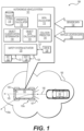
- FIG. 1 depicts one example of a system for implementing an active safety system in an autonomous vehicle.
- an autonomous vehicle 100 (depicted in top plan view) may be travelling through an environment 190 external to the autonomous vehicle 100 along a trajectory 105.
- environment 190 may include one or more objects that may potentially collide with the autonomous vehicle 100, such as static and/or dynamic objects, or objects that pose some other danger to passengers (not shown) riding in the autonomous vehicle 100 and/or to the autonomous vehicle 100.
- objects may potentially collide with the autonomous vehicle 100, such as static and/or dynamic objects, or objects that pose some other danger to passengers (not shown) riding in the autonomous vehicle 100 and/or to the autonomous vehicle 100.
- FIG. 1 depicts one example of a system for implementing an active safety system in an autonomous vehicle.
- an autonomous vehicle 100 may be travelling through an environment 190 external to the autonomous vehicle 100 along a trajectory 105.
- environment 190 may include one or more objects that may potentially collide with the autonomous vehicle 100, such as static and/or dynamic objects, or objects that
- an object 180 e.g., an automobile
- a trajectory 185 that if not altered (e.g., by changing trajectory, slowing down, etc.), may result in a potential collision 187 with the autonomous vehicle 100 (e.g., by rear-ending the autonomous vehicle 100).
- Autonomous vehicle 100 may use a sensor system (not shown) to sense (e.g., using passive and/or active sensors) the environment 190 to detect the object 180 and may take action to mitigate or prevent the potential collision of the object 180 with the autonomous vehicle 100.
- An autonomous vehicle system 101 may receive sensor data 132 from the sensor system and may receive autonomous vehicle location data 139 (e.g., implemented in a localizer system of the autonomous vehicle 100).
- the sensor data 132 may include but is not limited to data representing a sensor signal (e.g., a signal generated by a sensor of the sensor system).
- the data representing the sensor signal may be indicative of the environment 190 external to the autonomous vehicle 100.
- the autonomous vehicle location data 139 may include but is not limited to data representing a location of the autonomous vehicle 100 in the environment 190.
- the data representing the location of the autonomous vehicle 100 may include position and orientation data (e.g., a local position or local pose), map data (e.g., from one or more map tiles), data generated by a global positioning system (GPS) and data generated by an inertial measurement unit (IMU).
- a sensor system of the autonomous vehicle 100 may include a global positioning system, an inertial measurement unit, or both.
- Autonomous vehicle system 101 may include but is not limited to hardware, software, firmware, logic, circuitry, computer executable instructions embodied in a non-transitory computer readable medium, or any combination of the foregoing, to implement a path calculator 112, an object data calculator 114 (e.g., implemented in a perception system of the autonomous vehicle 100), a collision predictor 116, an object classification determinator 118 and a kinematics calculator 115.
- Autonomous vehicle system 101 may access one or more data stores including but not limited to object types data store 119.
- Object types data store 119 may include data representing object types associated with object classifications for objects detected in environment 190 (e.g., a variety of pedestrian object types such as "sitting,” “standing,” or “running,” may be associated with objects classified as pedestrians).
- Path calculator 112 may be configured to generate data representing a trajectory of the autonomous vehicle 100 (e.g., trajectory 105), using data representing a location of the autonomous vehicle 100 in the environment 190 and other data (e.g., local pose data included in vehicle location data 139), for example. Path calculator 112 may be configured to generate future trajectories to be executed by the autonomous vehicle 100, for example. In some examples, path calculator 112 may be implanted in or as part of a planner system of the autonomous vehicle 100. In other examples, the path calculator 112 and/or the planner system may calculate data associated with a predicted motion of an object in the environment and may determine a predicted object path associated with the predicted motion of the object. In some examples, the object path may constitute the predicted object path. In other examples, the object path may constitute a predicted object trajectory. In yet other examples, the object path (e.g., in the environment) may constitute a predicted object trajectory that may be identical to or similar to a predicted object trajectory.
- Object data calculator 114 may be configured to calculate data representing the location of the object 180 disposed in the environment 190, data representing an object track associated with the object 180, and data representing an object classification associated with the object 180, and the like. Object data calculator 114 may calculate the data representing the location of the object, the data representing the object track, and the data representing the object classification using data representing a sensor signal included in sensor data 132, for example. In some examples, the object data calculator 114 may be implemented in or may constitute a perception system, or a portion thereof, being configured to receive the data representing the sensor signal (e.g., a sensor signal from a sensor system).
- Object classification determinator 118 may be configured to access data representing object types 119 (e.g., a species of an object classification, a subclass of an object classification, or a subset of an object classification) and may be configured to compare the data representing the object track and the data representing the object classification with the data representing the object types 119 to determine data representing an object type (e.g., a species or subclass of the object classification).
- object types 119 e.g., a species of an object classification of a "car”
- An object type may include additional subclasses or subsets such as a "school bus” that is parked may have an additional subclass of "static” (e.g. the school bus is not in motion), or an additional subclass of "dynamic” (e.g. the school bus is in motion), for example.
- Collision predictor 116 may be configured to use the data representing the object type, the data representing the trajectory of the object and the data representing the trajectory of the autonomous vehicle to predict a collision (e.g., 187) between the autonomous vehicle 100 and the object 180, for example.
- a kinematics calculator 115 may be configured to compute data representing one or more scalar and/or vector quantities associated with motion of the object 180 in the environment 190, including but not limited to velocity, speed, acceleration, deceleration, momentum, local pose and force, for example. Data from kinematics calculator 115 may be used to compute other data including but not limited to data representing an estimated time to impact between the obj ect 180 and the autonomous vehicle 100 and data representing a distance between the object 180 and the autonomous vehicle 100, for example. In some examples the kinematics calculator 115 may be configured to predict a likelihood that other objects in the environment 190 (e.g.
- the kinematics calculator 115 may be configured estimate a probability that other agents (e.g., drivers or riders of other vehicles) are behaving rationally (e.g., based on motion of the object they are driving or riding), which may dictate behavior of the autonomous vehicle 100, versus behaving irrationally (e.g. based on erratic motion of the object they are riding or driving).
- agents e.g., drivers or riders of other vehicles
- behaving rationally e.g., based on motion of the object they are driving or riding
- behaving irrationally e.g. based on erratic motion of the object they are riding or driving
- Rational or irrational behavior may be inferred based on sensor data received over time that may be used to estimate or predict a future location of the object relative to a current or future trajectory of the autonomous vehicle 100. Consequently, a planner system of the autonomous vehicle 100 may be configured to implement vehicle maneuvers that are extra cautious and/or activate a safety system of the autonomous vehicle 100, for example.
- a safety system activator 120 may be configured to activate one or more safety systems of the autonomous vehicle 100 when a collision is predicted by the collision predictor 116 and/or the occurrence of other safety related events (e.g., an emergency maneuver by the vehicle 100, such as hard braking, sharp acceleration, etc.).
- Safety system activator 120 may be configured to activate an interior safety system 122, an exterior safety system 124, a drive system 126 (e.g., cause drive system 126 to execute an emergency maneuver to avoid the collision), or any combination of the foregoing.
- drive system 126 may receive data being configured to cause a steering system (e.g., set a steering angle or a steering vector for the wheels) and a propulsion system (e.g., power supplied to an electric motor) to alter the trajectory of vehicle 100 from trajectory 105 to a collision avoidance trajectory 105a.
- a steering system e.g., set a steering angle or a steering vector for the wheels
- a propulsion system e.g., power supplied to an electric motor
- FIG. 2A depicts one example of a flow diagram 200 for implementing an active safety system in an autonomous vehicle 100.
- data representing a trajectory 203 of an autonomous vehicle 100 in an environment external to the autonomous vehicle 100 may be received (e.g., implemented in a planner system of the autonomous vehicle 100).
- object data associated with an object e.g., automobile 180 disposed in the environment (e.g., environment 190) may be calculated.
- Sensor data 205 may be accessed at the stage 204 to calculate the object data.
- the object data may include but is not limited to data representing object location in the environment, an object track associated with the object (e.g., static for a non-moving object and dynamic for an object in motion), and an object classification (e.g., a label) associated with the object (e.g., pedestrian, dog, cat, bicycle, motorcycle, automobile, truck, etc.).
- the stage 204 may output one or more types of data associated with an object, including but not limited to data representing object location 207 in the environment, data representing an object track 209, and data representing an object classification 211.
- a predicted object path of the object in the environment may be calculated.
- the stage 206 may receive the data representing object location 207 and may process that data to generate data representing a predicted object path 213.
- data representing object types 215 may be accessed, and at a stage 210, data representing an object type 217 may be determined based on the data representing the object track 209, the data representing the object classification 211 and the data representing object types 215.
- object type may include but are not limited to a pedestrian object type having a static object track (e.g., the pedestrian is not in motion), an automobile object type having a dynamic object track (e.g., the automobile is in motion) and an infrastructure object type having a static object track (e.g., a traffic sign, a lane marker, a fire hydrant), etc., just to name a few.
- the stage 210 may output the data representing object type 217.
- a collision between the autonomous vehicle and the object may be predicted based on the determined object type 217, the autonomous vehicle trajectory 203 and the predicted object path 213.
- a collision may be predicted based in part on the determined object type 217 due to the object having an object track that is dynamic (e.g., the object is in motion in the environment), the trajectory of the object being in potential conflict with a trajectory of the autonomous vehicle (e.g., the trajectories may intersect or otherwise interfere with each other), and the object having an object classification 211 (e.g., used in computing the object type 217) that indicates the object is a likely collision threat (e.g., the object is classified as an automobile, a skateboarder, a bicyclists, a motorcycle, etc.).
- object classification 211 e.g., used in computing the object type 217
- a safety system of the autonomous vehicle may be activated when the collision is predicted (e.g., at the stage 212).
- the stage 214 may activate one or more safety systems of the autonomous vehicle, such as one or more interior safety systems, one or more exterior safety systems, one or more drive systems (e.g., steering, propulsion, braking, etc.) or a combination of the foregoing, for example.
- the stage 214 may cause (e.g., by communicating data and/or signals) a safety system activator 220 to activate one or more of the safety systems of the autonomous vehicle 100.
- FIG. 2B depicts another example of a flow diagram 250 for implementing an active safety system in an autonomous vehicle 100.
- data representing the trajectory 253 of an autonomous vehicle 100 in an environment external to the autonomous vehicle 100 may be received (e.g., from a planner system of the autonomous vehicle 100).
- a location of an object in the environment may be determined.
- Sensor data 255 may be processed (e.g., by a perception system) to determine data representing an object location in the environment 257.
- Data associated with an object e.g., object data associated with object 180
- environment e.g., environment 190
- Sensor data 255 accessed at the stage 254 may be used to determine the object data.
- the object data may include but is not limited to data representing a location of the object in the environment, an object track associated with the object (e.g., static for a non-moving object and dynamic for an object in motion), an object classification associated with the object (e.g., pedestrian, dog, cat, bicycle, motorcycle, automobile, truck, etc.) and an object type associated with the object.
- the stage 254 may output one or more types of data associated with an object, including but not limited to data representing the object location 257 in the environment, data representing an object track 261 associated with the object, data representing an object classification 263 associated with the object, and data representing an object type 259 associated with the object.
- a predicted object path of the object in the environment may be calculated.
- the stage 256 may receive the data representing the object location 257 and may process that data to generate data representing a predicted object path 265.
- the data representing the predicted object path 265, generated at the stage 256 may be used as a data input at another stage of flow diagram 250, such as at a stage 258.
- the stage 256 may be bypassed and flow diagram 250 may transition from the stage 254 to the stage 258.
- a collision between the autonomous vehicle and the object may be predicted based the autonomous vehicle trajectory 253 and the object location 265.
- the object location 257 may change from a first location to a next location due to motion of the object in the environment.
- the object may be in motion (e.g., has an object track of dynamic "D"), may be motionless (e.g., has an object track of static "S"), or both.
- the perception system may continually track the object (e.g., using sensor data from the sensor system) during those different points in time to determine object location 257 at the different point in times.
- the predicted object path 265 calculated at the stage 256 may be difficult to determine; therefore the predicted object path 265 need not be used as a data input at the stage 258.
- the stage 258 may predict the collision using data not depicted in FIG. 2B , such as object type 259 and predicted object path 265, for example.
- a collision between the autonomous vehicle and the object may be predicted based on the autonomous vehicle trajectory 253, the object location 257 and the object type 259.
- a collision between the autonomous vehicle and the object may be predicted based on the autonomous vehicle trajectory 253 and the predicted object path 265.
- a collision between the autonomous vehicle and the object may be predicted based on the autonomous vehicle trajectory 253, the predicted object path265 and the object type 259.
- a safety system of the autonomous vehicle may be activated when the collision is predicted (e.g., at the stage 258).
- the stage 260 may activate one or more safety systems of the autonomous vehicle, such as one or more interior safety systems, one or more exterior safety systems, one or more drive systems (e.g., steering, propulsion, braking, etc.) or a combination of the foregoing, for example.
- the stage 260 may cause (e.g., by communicating data and/or signals) a safety system activator 269 to activate one or more of the safety systems of the autonomous vehicle.
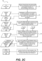
- FIG. 2C depicts yet another example of a flow diagram 270 for implementing an active safety system in an autonomous vehicle.
- data representing the trajectory 273 of an autonomous vehicle 100 in an environment external to the autonomous vehicle 100 may be received (e.g., from a planner system of the autonomous vehicle 100).
- a location of an object in the environment may be determined (e.g., by a perception system) using sensor data 275, for example.
- the stage 274 may generate data representing object location 279.
- the data representing the object location 279 may include data representing a predicted rate of motion 281 of the object relative to the location of the object in the environment. For example, if the object has a static object track indicative of no motion in the environment, then the predictive rate of motion 281 may be zero. However, if the object track of the object is dynamic and the object classification is an automobile, then the predicted rate of motion 281 may be non-zero.
- a predicted next location of the object in the environment may be calculated based on the predicted rate of motion 281.
- the stage 276 may generate data representing the predicted next location 283.
- probabilities of impact between the object and the autonomous vehicle may be predicted based on the predicted next location 283 and the autonomous vehicle trajectory 273.
- the stage 278 may generate data representing the probabilities of impact 285.
- subsets of thresholds (e.g., a location or a distance in the environment) to activate different escalating functions of subsets of safety systems of the autonomous vehicle may be calculated based on the probabilities of impact 285. At least one subset of the thresholds being associated with the activation of different escalating functions of a safety system of the autonomous vehicle.
- the stage 280 may generate data representing one or more threshold subsets 287.
- the subsets of thresholds may constitute a location relative to the autonomous vehicle or may constitute a distance relative to the autonomous vehicle.
- a threshold may be a function of a location or a range of locations relative to a reference location (e.g., the autonomous vehicle).
- a threshold may be a function of distance relative to an object and the autonomous vehicle, or between any objects or object locations, including distances between predicted object locations.
- FIG. 3A depicts one example 300 of a system for implementing an active safety system in an autonomous vehicle.
- autonomous vehicle system 301 may include a sensor system 320 including sensors 328 being configured to sense the environment 390 (e.g., in real-time or in near-real-time) and generate (e.g., in real-time) sensor data 332 and 334 (e.g., data representing a sensor signal).
- Autonomous vehicle system 301 may include a perception system 340 being configured to detect objects in environment 390, determine an object track for objects, classify objects, track locations of objects in environment 390, and detect specific types of objects in environment 390, such as traffic signs/lights, road markings, lane markings and the like, for example.
- Perception system 340 may receive the sensor data 334 from a sensor system 320.
- perception system 330 may receive data 334 from sensors including but not limited to LIDAR (e.g., 2D, 3D, color LIDAR), RADAR, and Cameras (e.g., image capture devices); whereas, localizer system 330 may receive data 332 including but not limited to global positioning system (GPS) data, inertial measurement unit (IMU) data, map data, route data, Route Network Definition File (RNDF) data and map tile data.
- Localizer system 330 may receive data from sources other than sensor system 320, such as a data store, data repository, memory, etc.
- sensor data 332 received by localizer system 330 may be identical to the sensor data 334 received by the perception system 340.
- localizer system 330 and perception system 340 mayor may not implement similar or equivalent sensors or types of sensors. Further, localizer system 330 and perception system 340 each may implement any type of sensor data 332 independently of each other.
- Localizer system 330 may process sensor data 334, and optionally, other data, to generate position and orientation data, local pose data 339 that may be received by the planner system 310.
- the local pose data 339 may include, but is not limited to, data representing a location of the autonomous vehicle in the environment 390, GPS data, IMU data, map data, route data, Route Network Definition File (RNDF) data, odometry data, wheel encoder data, and map tile data, for example.
- RDF Route Network Definition File
- Planner system 310 may be configured to communicate control and data 317 with one or more vehicle controllers 350.
- Control and data 317 may include information configured to control driving operations of the autonomous vehicle (e.g., steering, braking, propulsion, signaling, etc.) via a drive system 326, to activate one or more interior safety systems 322 of the autonomous vehicle and to activate one or more exterior safety systems 324 of the autonomous vehicle.
- Drive system 326 may perform additional functions associated with active safety of the autonomous vehicle, such as collision avoidance maneuvers, for example.
- Vehicle controller(s) 350 may be configured to receive the control and data 317, and based on the control and data 317, communicate interior data 323, exterior data 325 and drive data 327 to the interior safety system 322, the exterior safety system 324, and the drive system 326, respectively, as determined by the control and data 317, for example.
- control and data 317 may include information configured to cause the vehicle controller 350 to generate interior data 323 to activate one or more functions of the interior safety system 322.
- the autonomous vehicle system 301 and its associated systems 310, 320, 330, 340, 350, 322, 324 and 326 may be configured to access data 315 from a data store 311 (e.g., a data repository) and/or data 312 from an external resource 313 (e.g., the Cloud, the Internet, a wireless network).
- the autonomous vehicle system 301 and its associated systems 310, 320, 330, 340, 350, 322, 324 and 326 may be configured to access, in real-time, data from a variety of systems and/or data sources including but not limited to those depicted in FIG. 3A .
- localizer system 330 and perception system 340 may be configured to access in real-time the sensor data 332 and the sensor data 334.
- the planner system 310 may be configured to access in real-time the object data 349, the local pose data 339 and control and data 317. In other examples, the planner system 310 may be configured to access in real-time the data store 311 and/or the external resource 313.
- FIG. 3B depicts another example 399 of a system for implementing an active safety system in an autonomous vehicle.
- sensors 328 in sensor system 320 may include but are not limited to one or more of: Light Detection and Ranging sensors 371 (LIDAR); image capture sensors 373 (e.g., Cameras); Radio Detection And Ranging sensors 375 (RADAR); sound capture sensors 377 (e.g., Microphones); Global Positioning System sensors (GPS) and/or Inertial Measurement Unit sensors (IMU) 379; and Environmental sensor(s) 372 (e.g., temperature, barometric pressure), for example.
- LIDAR Light Detection and Ranging sensors 371
- image capture sensors 373 e.g., Cameras
- Radio Detection And Ranging sensors 375 RADAR
- sound capture sensors 377 e.g., Microphones
- GPS Global Positioning System sensors
- IMU Inertial Measurement Unit sensors
- Environmental sensor(s) 372 e.g.
- Localizer system 330 and perception system 340 may receive sensor data 332 and/or sensor data 334, respectively, from one or more of the sensors 328.
- perception system 340 may receive sensor data 334 relevant to determine information associated with objects in environment 390, such as sensor data from LIDAR 371, Cameras 373, RADAR 375, Environmental 372, and Microphones 377; whereas, localizer system 330 may receive sensor data 332 associated with the location of the autonomous vehicle in environment 390, such as from GPS/IMU 379.
- localizer system 330 may receive data from sources other than the sensor system 320, such as map data, map tile data, route data, Route Network Definition File (RNDF) data, a data store, a data repository, etc., for example.
- RDF Route Network Definition File
- sensor data (332, 334) received by localizer system 330 may be identical to the sensor data (332, 334) received by the perception system 340. In other examples, sensor data (332, 334) received by localizer system 330 may not be identical to the sensor data (332, 334) received by the perception system 340.
- Sensor data 332 and 334 each may include data from any combination of one or more sensors or sensor types in sensor system 320. The amounts and types of sensor data 332 and 334 may be independent from the other and mayor may not be similar or equivalent.
- localizer system 330 may receive and/or access data from sources other than sensor data (332, 334) such as odometry data 336 from motion sensors to estimate a change in position of the autonomous vehicle 100 over time, wheel encoders 337 to calculate motion, distance and other metrics of the autonomous vehicle 100 based on wheel rotations (e.g., by propulsion system 368), map data 335 from data representing map tiles, route data, Route Network Definition File (RNDF) data and/or others, and data representing an autonomous vehicle (AV) model 338 that may be used to calculate vehicle location data based on models of vehicle dynamics (e.g., from simulations, captured data, etc.) of the autonomous vehicle 100.
- Localizer system 330 may use one or more of the data resources depicted to generate data representing local pose data 339.
- perception system 340 may parse or otherwise analyze, process, or manipulate sensor data (332, 334) to implement object detection 341, object track 343 (e.g., determining which detected objects are static (no motion) and which are dynamic (in motion)), object classification 345 (e.g., cars, motorcycle, bike, pedestrian, skate boarder, mailbox, buildings, street lights, etc.), object tracking 347 (e.g., tracking an object based on changes in a location of the object in the environment 390), and traffic light/sign detection 342 (e.g., stop lights, stop signs, rail road crossings, lane markers, pedestrian cross-walks, etc.).
- object detection 341 object track 343 (e.g., determining which detected objects are static (no motion) and which are dynamic (in motion))
- object classification 345 e.g., cars, motorcycle, bike, pedestrian, skate boarder, mailbox, buildings, street lights, etc.
- object tracking 347 e.g., tracking an object based on changes in a location of
- planner system 310 may receive the local pose data 339 and the object data 349 and may parse or otherwise analyze, process, or manipulate data (local pose data 339, object data 349) to implement functions including but not limited to trajectory calculation 381, threshold location estimation 386, audio signal selection 389, light pattern selection 382, kinematics calculation 384, object type detection 387, collision prediction 385 and object data calculation 383, for example.
- Planner system 310 may communicate trajectory and control data 317 to a vehicle controller(s) 350.
- Vehicle controller(s) 350 may process the vehicle control and data 317 to generate drive system data 327, interior safety system data 323 and exterior safety system data 325.
- Drive system data 327 may be communicated to a drive system 326.
- Drive system 326 may communicate the drive system data 327 to a braking system 364, a steering system 366, a propulsion system 368, and a signal system 362 (e.g., turn signals, brake signals, headlights, and running lights).
- drive system data 327 may include steering angle data for steering system 366 (e.g., a steering angle for a wheel), braking data for brake system 364 (e.g., brake force to be applied to a brake pad), and propulsion data (e.g., a voltage, current or power to be applied to a motor) for propulsion system 368.
- a dashed line 377 may represent a demarcation between a vehicle trajectory processing layer and a vehicle physical execution layer where data processed in the vehicle trajectory processing layer is implemented by one or more of the drive system 326, the interior safety system 322 or the exterior safety system 324.
- one or more portions of the interior safety system 322 may be configured to enhance the safety of passengers in the autonomous vehicle 100 in the event of a collision and/or other extreme event (e.g., a collision avoidance maneuver by the autonomous vehicle 100).
- one or more portions of the exterior safety system 324 may be configured to reduce impact forces or negative effects of the aforementioned collision and/or extreme event.
- Systems in exterior safety system 324 may be configured to interface with the environment 390 by emitting light into the environment 390 using one or more light emitters (not shown) in the light emitter system 367, emitting a steered beam of acoustic energy (e.g., sound) into the environment 390 using one or more acoustic beam-steering arrays (not shown) in the acoustic beam-steering array 365 or by expanding one or more bladders (not shown) in the bladder system 369 from an un-deployed position to a deployed position, or any combination of the foregoing.
- acoustic energy e.g., sound
- the acoustic beam-steering array 365 may emit acoustic energy into the environment using transducers, air horns, or resonators, for example.
- the acoustic energy may be omnidirectional, or may constitute a steered beam, or otherwise focused sound (e.g., a directional acoustic source, a phased array, a parametric array, a large radiator, of ultrasonic source).
- systems in exterior safety system 324 may be positioned at one or more locations of the autonomous vehicle 100 configured to allow the systems to interface with the environment 390, such as a location associated with an external surface (e.g., 100e in FIG. 1 ) of the autonomous vehicle 100.
- Systems in interior safety system 322 may be positioned at one or more locations associated with an interior (e.g., 100i in FIG. 1 ) of the autonomous vehicle 100 and may be connected with one or more structures of the autonomous vehicle 100, such as a seat, a bench seat, a floor, a rail, a bracket, a pillar, or other structure.
- the seat belt tensioning system 361 and the seat actuator system 363 may be coupled with one or more structures configured to support mechanical loads that may occur due to a collision, vehicle acceleration, vehicle deceleration, evasive maneuvers, sharp turns, hard braking, etc., for example.
- FIG. 4 depicts one example of a flow diagram 400 for implementing a perception system in an autonomous vehicle.
- sensor data 434 e.g., generated by one or more sensors in sensor system 420
- perception system 440 is depicted visually as sensor data 434a - 434c (e.g., LIDAR data, color LIDAR data, 3D LIDAR data).
- sensor data 434a - 434c e.g., LIDAR data, color LIDAR data, 3D LIDAR data.
- a determination may be made as to whether or not the sensor data 434 includes data representing a detected object. If a NO branch is taken, then flow diagram 400 may return to the stage 402 to continue analysis of sensor data 434 to detect object in the environment.
- flow diagram 400 may continue to a stage 404 where a determination may be made as to whether or not the data representing the detected object includes data representing a traffic sign or light. If a YES branch is taken, then flow diagram 400 may transition to a stage 406 where the data representing the detected object may be analyzed to classify the type of light/sign object detected, such as a traffic light (e.g., red, yellow, and green) or a stop sign (e.g., based on shape, text and color), for example. Analysis at the stage 406 may include accessing a traffic object data store 424 where examples of data representing traffic classifications may be compared with the data representing the detected object to generate data representing a traffic classification 407. The stage 406 may then transition to another stage, such as a stage 412. In some examples, the stage 404 may be optional, and the stage 402 may transition to a stage 408.
- a traffic light e.g., red, yellow, and green
- a stop sign e.g., based on shape, text and color
- flow diagram 400 may transition to the stage 408 where the data representing the detected object may be analyzed to determine other object types to be classified. If a YES branch is taken, then flow diagram 400 may transition to a stage 410 where the data representing the detected object may be analyzed to classify the type of object.
- An object data store 426 may be accessed to compare stored examples of data representing object classifications with the data representing the detected object to generate data representing an object classification 411. The stage 410 may then transition to another stage, such as a stage 412. If a NO branch is taken from the stage 408, then stage 408 may transition to another stage, such as back to the stage 402.
- a YES branch may be taken to a stage 418 where data representing an object track for the detected object may be set to dynamic (D).
- data representing a location of the object e.g., the dynamic object
- the planner system may analyze the data representing the object track and/or the data representing the location of the object to determine if a detected object (static or dynamic) may potentially have a conflicting trajectory with respect to the autonomous vehicle and/or come into too close a proximity of the autonomous vehicle, such that an alert (e.g., from a light emitter and/or from an acoustic beam-steering array) may be used to alter a behavior of the object and/or the person controlling the object.
- an alert e.g., from a light emitter and/or from an acoustic beam-steering array
- one or more of the data representing the object classification, the data representing the object track, and the data representing the location of the object may be included with the object data 449 (e.g., the object data received by the planner system).
- sensor data 434a may include data representing an object (e.g., a person riding a skateboard).
- Stage 402 may detect the object in the sensor data 434a.
- it may be determined that the detected object is not a traffic sign/light.
- the stage 408 may determine that the detected object is of another class and may analyze at a stage 410, based on data accessed from object data store 426, the data representing the object to determine that the classification matches a person riding a skateboard and output data representing the object classification 411.
- the object track may be set to dynamic (D) and the location of the object may be tracked at the stage 419 (e.g., by continuing to analyze the sensor data 434a for changes in location of the detected object).
- the object data associated with sensor data 434 may include the classification (e.g., a person riding a skateboard), the object track (e.g., the object is in motion), the location of the object (e.g., the skateboarder) in the environment external to the autonomous vehicle) and object tracking data for example.
- flow diagram 400 may determine that the object classification is a pedestrian, the pedestrian is in motion (e.g., is walking) and has a dynamic object track, and may track the location of the object (e.g., the pedestrian) in the environment, for example.
- flow diagram 400 may determine that the object classification is a fire hydrant, the fire hydrant is not moving and has a static object track, and may track the location of the fire hydrant.
- the object data 449 associated with sensor data 434a, 434b, and 434c may be further processed by the planner system based on factors including but not limited to object track, object classification and location of the object, for example.
- the object data 449 may be used for one or more of trajectory calculation, threshold location estimation, motion prediction, location comparison, and object coordinates, in the event the planner system decides to implement an alert (e.g., by an exterior safety system) for the skateboarder and/or the pedestrian.
- an alert e.g., by an exterior safety system
- the planner system may decide to ignore the object data for the fire hydrant due its static object track because the fire hydrant is not likely to have a motion (e.g., it is stationary) that will conflict with the autonomous vehicle and/or because the fire hydrant is non-animate (e.g., can't respond to or be aware of an alert, such as emitted light and/or beam steered sound), generated by an exterior safety system of the autonomous vehicle), for example.
- an alert such as emitted light and/or beam steered sound
- FIG. 5 depicts one example 500 of object prioritization by a planner system in an autonomous vehicle.
- Example 500 depicts a visualization of an environment 590 external to the autonomous vehicle 100 as sensed by a sensor system of the autonomous vehicle 100 (e.g., sensor system 320 of FIG. 3B ).
- Object data from a perception system of the autonomous vehicle 100 may detect several objects in environment 590 including but not limited to an automobile 581d, a bicycle rider 583d, a walking pedestrian 585d, and two parked automobiles 5875 and 5895.
- a perception system may have assigned (e.g., based on sensor data 334 of FIG.
- the perception system may also have assigned (e.g., based on sensor data 334 of FIG. 3B ) static "S" object tracks to objects 5875 and 5895, thus the label "s" is associated with the reference numerals for those objects.
- a localizer system of the autonomous vehicle may determine the local pose data 539 for a location of the autonomous vehicle 100 in environment 590 (e.g., X, Y, Z coordinates relative to a location on vehicle 100 or other metric or coordinate system).
- the local pose data 539 may be associated with a center of mass (not shown) or other reference point of the autonomous vehicle 100.
- autonomous vehicle 100 may have a trajectory Tav as indicated by the arrow.
- the two parked automobiles 5875 and 5895 are static and have no indicated trajectory.
- Bicycle rider 583d has a trajectory Tb that is in a direction approximately opposite that of the trajectory Tav
- automobile 581 d has a trajectory Tmv that is approximately parallel to and in the same direction as the trajectory Tav.
- the planner system may place a lower priority on tracking the location of static objects 5875 and 5895 and dynamic object 583d because the static objects 5875 and 5895 are positioned out of the way of trajectory Tav (e.g., objects 5875 and 5895 are parked) and dynamic object 583d (e.g., an object identified as a bicyclist) is moving in a direction away from the autonomous vehicle 100; thereby, reducing or eliminating a possibility that trajectory Tb of object 583d may conflict with trajectory Tav of the autonomous vehicle 100.
- trajectory Tav e.g., objects 5875 and 5895 are parked
- dynamic object 583d e.g., an object identified as a bicyclist
- the planner system may place a higher priority on tracking the location of pedestrian 585d due to its potentially conflicting trajectory Tp, and may place a slightly lower priority on tracking the location of automobile 581d because its trajectory Tmv is not presently conflicting with trajectory Tav, but it may conflict at a later time (e.g., due to a lane change or other vehicle maneuver).
- pedestrian object 585d may be a likely candidate for an alert (e.g., using steered sound and/or emitted light) or other safety system of the autonomous vehicle 100, because the path of the pedestrian object 585d (e.g., based on its location and/or predicted motion) may result in a potential collision (e.g., at an estimated location 560) with the autonomous vehicle 100 or result in an unsafe distance between the pedestrian object 585d and the autonomous vehicle 100 (e.g., at some future time and/or location).
- a priority placed by the planner system on tracking locations of objects may be determined, at least in part, on a cost function of trajectory generation in the planner system.
- the parametric range may be based in part on parameters such as a range of time and/or a range of distances. For example, a range of time and/or a range of distances in which a predicted collision between the object 585d and the autonomous vehicle 100 may occur.
- being a likely candidate for an alert by a safety system of the autonomous vehicle 100 does not automatically result in an actual alert being issued (e.g., as determine by the planner system).
- am object may be a candidate when a threshold is met or surpassed.
- a safety system of the autonomous vehicle 100 may issue multiple alerts to one or more objects in the environment external to the autonomous vehicle 100.
- the planner system may implement a safe-stop maneuver or a safe-stop trajectory using the bi-directional 680 travel capabilities to avoid a collision with an object, for example.
- the autonomous vehicle 100 may be traveling in a first direction, come to a stop, and begin travel in a second direction that is opposite the first direction, and may maneuver to a safe-stop location to avoid a collision or other extreme event.
- planner system may determine the location of the pedestrian object 585d at the point 602 (e.g., having coordinates X1, Y1 of either a relative or an absolute reference frame) and the coordinates of a location of the autonomous vehicle 100 (e.g., from local pose data).
- the location data for the autonomous vehicle 100 and the object may be used to calculate a location (e.g., coordinates, an angle, a polar coordinate) for the direction of propagation (e.g., a direction of the main lobe or focus of the beam) of a beam of steered acoustic energy (e.g., an audio alert) emitted by an acoustic beam-steering array (e.g., one or more of a directional acoustic source, a phased array, a parametric array, a large radiator, a ultrasonic source, etc.), may be used to determine which light emitter to activate for a visual alert, may be used to determine which bladder(s) to activate prior to a predicted collision with an object, and may be used to activate other safety systems and/or the drive system of the autonomous vehicle 100, or any combination of the foregoing.
- a location e.g., coordinates, an angle, a polar coordinate
- a location e.g.,
- the relative locations of the pedestrian object 585d and the autonomous vehicle 100 may change, such that at the location L2, the object 585d has coordinates (X2, Y2) at point 604 of the second threshold location 603.
- continued travel in the direction 625 along trajectory Tav, from location L2 to location L3 may change the relative locations of the pedestrian object 585d and the autonomous vehicle 100, such that at the location L3, the object 585d has coordinates (X3, Y3) at point 606 of the third threshold location 605.
- the data representing the alert selected for a safety system may be different to convey an increasing sense of urgency (e.g., an escalating threat level) to the pedestrian object 585d to change or halt its trajectory Tp, or otherwise modify his/her behavior to avoid a potential collision or close pass with the vehicle 100.
- the data representing the alert selected for threshold location 601 when the vehicle 100 may be at a relatively safe distance from the pedestrian object 585d, may be a less alarming nonthreatening alert a1 configured to garner the attention of the pedestrian object 585d in a non-threatening manner.
- the data representing the alerts may be configured to convey an increasing escalation of urgency to pedestrian object 585d (e.g., escalating acoustic and/or visual alerts to gain the attention of pedestrian object 585d).
- Estimation of positions of the threshold locations in the environment 590 may be determined by the planner system to provide adequate time (e.g., approximately 5 seconds or more), based on a velocity of the autonomous vehicle, before the vehicle 100 arrives at a predicted impact point 560 with the pedestrian object 585d (e.g., a point 560 in environment 590 where trajectories Tav and Tp are estimated to intersect each other).
- Point 560 may change as the speed and/or location of the object 585d, the vehicle 100, or both changes.
- the planner system of the autonomous vehicle 100 may be configured to actively attempt to avoid potential collisions (e.g., by calculating alternative collision avoidance trajectories and executing one or more of those trajectories) by calculating (e.g., continuously) safe trajectories (e.g., when possible based on context), while simultaneously, issuing alerts as necessary to objects in the environment when there is a meaningful probability the objects may collide or otherwise pose a danger to the safety of passengers in the autonomous vehicle 100, to the object, or both.
- active alerts e.g., acoustic and/or visual alerts
- the planner system of the autonomous vehicle 100 may be configured to actively attempt to avoid potential collisions (e.g., by calculating alternative collision avoidance trajectories and executing one or more of those trajectories) by calculating (e.g., continuously) safe trajectories (e
- threshold locations (601, 603 and 605) in example 600 are aligned approximately perpendicular to the trajectory Tp of pedestrian object 585d; however, other configurations and orientations may be calculated and implemented by the planner system (e.g., see examples 650 and 670).
- threshold locations may be aligned approximately perpendicular (or other orientation) to the trajectory Tav of the autonomous vehicle 100.
- the trajectory of the object may be analyzed by the planner system to determine the configuration of the threshold location(s).
- the threshold location(s) may have an arcuate profile and may be aligned with the trajectory of the object.
- skateboarder object 434a may require processing for an alert (e.g., using emitted light, steered sound or both) due to it being a dynamic object and other factors, such as predicted human behavior of skateboard riders, a location of the skateboarder object 434a in the environment that may indicate the location (e.g., a predicted location) may conflict with a trajectory of the autonomous vehicle 100, for example.
- an example of three detected objects is denoted as 734a - 734c.
- object data 749 for more or fewer detected objects as denoted by 734.
- the object data for each detected object may include but is not limited to data representing: object location 721; object classification 723; and object track 725.
- Planner system 710 may be configured to implement obj ect type determination 731.
- Obj ect type determination 731 may be configured to receive the data representing object classification 723, the data representing the object track 725 and data representing object types that may be accessed from an object types data store 724.
- Object dynamics determination 735 may be configured to receive the data representing the object type 733 and the data representing the object location 721. Object dynamics determination 735 may be further configured to access an object dynamics data store 726. Object dynamics data store 726 may include data representing object dynamics. Object dynamics determination 735 may be configured to compare data representing object dynamics with the data representing the object type 733 and the data representing the object location 721 to determine data representing a predicted object motion 737.
- Object location predictor 741 may be configured to receive the data representing the predicted object motion 737, the data representing the location of the autonomous vehicle 743 (e.g., from local pose data 739), the data representing the object location 721 and the data representing the object track 725.
- the object location predictor 741 may be configured to process the received data to generate data representing a predicted object location 745 in the environment.
- Object location predictor 741 may be configured to generate data representing more than one predicted object location 745.
- the planner system 710 may generate data representing regions of probable locations (e.g., 565 in FIGS. 5 and 6 ) of an object.
- Threshold location estimator 747 may be configured to receive the data representing the location of the autonomous vehicle 743 (e.g., from local pose data 739) and the data representing the predicted object location 745 and generate data representing one or more threshold locations 750 in the environment associated with an alert to be triggered (e.g., a visual alert and/or an acoustic alert), or associated with activation of one or more safety systems of vehicle 100, for example.
- the one or more threshold locations 750 may be located with the regions of probable locations (e.g., 601, 603 and 605 within 565 in FIG. 6 ).
- FIG. 8 depicts one example 800 of a block diagram of systems in an autonomous vehicle.
- the autonomous vehicle 100 may include a suite of sensors 820 positioned at one or more locations on the autonomous vehicle 100.
- Each suite 820 may have sensors including but not limited to LIDAR 821 (e.g., color LIDAR, three-dimensional color LIDAR, two-dimensional LIDAR, etc.), an image capture device 823 (e.g., a digital camera), RADAR 825, a microphone 827 (e.g., to capture ambient sound), and a loudspeaker 829 (e.g., to greet/communicate with passengers of the AV 100).
- LIDAR 821 e.g., color LIDAR, three-dimensional color LIDAR, two-dimensional LIDAR, etc.
- an image capture device 823 e.g., a digital camera
- RADAR 825 e.g., a microphone
- microphone 827 e.g., to capture ambient sound
- Microphones 871 (e.g., to may be configured to capture sound from drive system components such as propulsion systems and/or braking systems) and may be positioned at suitable locations proximate to drive system components to detect sound generated by those components, for example.
- Each suite of sensors 820 may include more than one of the same types of sensor, such as two image capture devices 823, or microphone 871 positioned proximate to each wheel 852, for example.
- Microphone 871 may be configured to capture audio signals indicative of drive operations of the autonomous vehicle 100.
- Microphone 827 may be configured to capture audio signals indicative of ambient sounds in the environment external to the autonomous vehicle 100. Multiple microphones 827 may be paired or otherwise grouped to generate signals that may be processed to estimate sound source location of sounds originating in the environment 890, for example.
- Autonomous vehicle 100 may include sensors for generating data representing location of the autonomous vehicle 100, and those sensors may include but are not limited to a global positioning system (GPS) 839a and/or an inertial measurement unit (IMU) 839b.
- Autonomous vehicle 100 may include one or more sensors ENV 877 for sensing environmental conditions in the environment external to the autonomous vehicle 100, such as air temperature, air pressure, humidity, barometric pressure, etc. Data generated by sensor(s) ENV 877 may be used to calculate the speed of sound in processing of data used by array(s) 102 (see arrays 102 depicted in FIG. 9 ), such as wave front propagation times, for example.
- GPS global positioning system
- IMU inertial measurement unit
- Autonomous vehicle 100 may include one or more sensors MOT 888 configured to detect motion of the vehicle 100 (e.g., motion due to an impact from a collision, motion due to an emergency/evasive maneuvering, etc.).
- sensor MOT 888 may include but is not limited to an accelerometer, a multi-axis accelerometer and a gyroscope.
- Autonomous vehicle 100 may include one or more rotation sensors (not shown) associated with wheels 852 and configured to detect rotation 853 of the wheel 852 (e.g., a wheel encoder).
- each wheel 852 may have an associated wheel encoder configured to detect rotation of the wheel 852 (e.g., an axle of the wheel 852 and/or a propulsion component of the wheel 852, such as an electric motor, etc.).
- Data representing a rotation signal generated by the rotation sensor may be received by one or more systems of the autonomous vehicle 100, such as the planner system, the localizer system, the perception system, the drive system, and one or more of the safety systems, for example.
- a communications network 815 may route signals and/or data to/from sensors, one or more safety systems 875 (e.g., a bladder, a seat actuator, a seat belt tensioner), and other components of the autonomous vehicle 100, such as one or more processors 810 and one or more routers 830, for example.
- safety systems 875 e.g., a bladder, a seat actuator, a seat belt tensioner
- other components of the autonomous vehicle 100 such as one or more processors 810 and one or more routers 830, for example.
- Routers 830 may route signals and/or data from: sensors in sensors suites 820, one or more acoustic beam-steering arrays 102 (e.g., one or more of a directional acoustic source, a phased array, a parametric array, a large radiator, of ultrasonic source), one or more light emitters, between other routers 830, between processors 810, drive operation systems such as propulsion (e.g., electric motors 851), steering, braking, one or more safety systems 875, etc., and a communications system 880 (e.g., for wireless communication with external systems and/or resources).
- acoustic beam-steering arrays 102 e.g., one or more of a directional acoustic source, a phased array, a parametric array, a large radiator, of ultrasonic source
- one or more light emitters between other routers 830, between processors 810, drive operation systems such as propulsion (e.g.
- one or more microphones 827 may be configured to capture ambient sound in the environment 890 external to the autonomous vehicle 100. Signals and/or data from microphones 827 may be used to adjust gain values for one or more speakers positioned in one or more of the acoustic beam-steering arrays (not shown). As one example, loud ambient noise, such as emanating from a construction site may mask or otherwise impair audibility of the beam of steered acoustic energy 104 being emitted by an acoustic beam-steering array. Accordingly, the gain may be increased or decreased based on ambient sound (e.g., in dB or other metric such as frequency content).
- the signals and/or data generated by microphones 871 may be indicative of a velocity of the vehicle 100 and as the vehicle 100 slows to a stop at a pedestrian cross-walk, the data representing the audio signal may be modulated by changes in the signals and/or data generated by microphones 871 as the velocity of the vehicle 100 changes.
- the signals and/or data generated by microphones 871 that are indicative of the velocity of the vehicle 100 may be used as the data representing the audio signal and as the velocity of the vehicle 100 changes, the sound being emitted by the acoustic beam-steering array 102 may be indicative of the change in velocity of the vehicle 100.
- the sound may be changed (e.g., in volume, frequency, etc.) based on velocity changes.
- the above examples may be implemented to audibly notify pedestrians that the autonomous vehicle 100 has detected their presence at the cross-walk and is slowing to a stop.
- One or more processors 810 may be used to implement one or more of the planner system, the localizer system, the perception system, one or more safety systems, and other systems of the vehicle 100, for example.
- One or more processors 810 may be configured to execute algorithms embodied in a non-transitory computer readable medium, to implement one or more of the planner system, the localizer system, the perception system, one or more safety systems, or other systems of the vehicle 100, for example.
- the one or more processors 810 may include but are not limited to circuitry, logic, field programmable gate array (FPGA), application specific integrated circuits (ASIC), programmable logic, a digital signal processor (DSP), a graphics processing unit (GPU), a microprocessor, a microcontroller, a big fat computer (BFC) or others, or clusters thereof.
- FPGA field programmable gate array
- ASIC application specific integrated circuits
- DSP digital signal processor
- GPU graphics processing unit
- microprocessor a microcontroller
- BFC big fat computer
- FIG. 9 depicts a top view of one example 900 of an acoustic beam-steering array in an exterior safety system of an autonomous vehicle.
- sensor suites e.g., 820 in FIG. 8
- enclosures for acoustic beam-steering arrays 102 may be positioned on an upper surface 100u (e.g., on a roof or other locations on the vehicle) of the autonomous vehicle 100 and may be positioned to direct their respective beams of steered acoustic energy 104 (e.g., see FIG. 11 ) outward into the environment towards a location of an object targeted to receive an acoustic alert.
- Acoustic beam-steering arrays 102 may be configured to provide coverage of steered acoustic energy at one or more objects disposed in the environment external to the autonomous vehicle 100 and the coverage may be in an arc of about 360 degrees around the autonomous vehicle 100, for example.
- the acoustic beam-steering arrays 102 need not be the same size, shape, or have the same number of speakers.
- the acoustic beam-steering arrays 102 need not be linear as depicted in FIG. 9 . Further to FIG.
- acoustic beam-steering arrays 102 denoted as C and D have different dimensions than acoustic beam-steering arrays 102 denoted as A and B.
- Sensor suites 820 may be positioned to provide sensor coverage of the environment external to the autonomous vehicle 100 for one acoustic beam-steering array 102 or multiple acoustic beam-steering arrays 102. In the case of multiple acoustic beam-steering arrays 102, the sensor suites 820 may provide overlapping regions of sensor coverage.
- a perception system of the autonomous vehicle 100 may receive sensor data from more than one sensor or suite of sensors to provide data for the planning system to implement activation of one or more of the arrays 102 to generate an acoustic alert and/or to activate one or more other safety systems of vehicle 100, for example.
- the autonomous vehicle 100 may not have a front (e.g., a hood) or a rear (e.g., a trunk) and therefore may be configured for driving operations in at least two different directions as denoted by arrow 980.
- the acoustic beam-steering arrays 102 may not have a front or rear designation and depending on which direction the autonomous vehicle 100 is driving in, array 102 (A) may be the array facing the direction of travel or array 102 (B) may be the array facing the direction of travel.
- Other safety systems of the autonomous vehicle 100 may be disposed at interior 100i (shown in dashed line) and exterior 100e locations on the autonomous vehicle 100 and may be activated for generating alerts or other safety functions by the planner system using the sensor data from the sensor suites.
- the overlapping regions of sensor coverage may be used by the planner system to activate one or more safety systems in response to multiple objects in the environment that may be positioned at locations around the autonomous vehicle 100.
- FIGS. 10A - 10B depicts top plan views of examples of sensor coverage.
- one of the four sensor suites 820 may provide sensor coverage 1011, using one or more of its respective sensors, of the environment 1090 in a coverage region that may be configured to provide sensor data for one or more systems, such as a perception system, localizer system, planner system and safety systems of the autonomous vehicle 100, for example.
- arrows A, B, C and D demarcate four quadrants 1 - 4 that surround the autonomous vehicle 100.
- sensor coverage 1011 by a single suite 820 may be partial sensor coverage because there may be partial senor blind spots not covered by the single suite 820 in quadrants 1, 3 and 4, and full sensor coverage in quadrant 2.
- the overlapping sensor regions of coverage may allow for redundancy in sensor coverage if one or more sensor suites 820 and/or one or more of their respective sensors (e.g., LIDAR, Camera, RADAR, etc.) are damaged, malfunction, or are otherwise rendered inoperative.
- One or more of the sensor coverage patterns 1011, 1021, 1031 and 1041 may allow the planner system to implement activation of one or more safety systems based on the position of those safety systems on the autonomous vehicle 100.
- bladders of a bladder safety system positioned on a side of the autonomous vehicle 100 e.g., the side of the vehicle 100 with arrow C
- FIG. 11A depicts one example of an acoustic beam-steering array in an exterior safety system of an autonomous vehicle.
- control data 317 from planner system 310 may be communicated to vehicle controller 350 which may in turn communicate exterior data 325 being configured to implement an acoustic alert by acoustic beam-steering array 102.
- the autonomous vehicle 100 may include more than one array 102 as denoted by 1103 (e.g., see arrays 102 in FIG. 9 ).
- Exterior data 325 received by array 102 may include but is not limited to object location data 1148 (e.g., a coordinate of object 1134 in the environment 1190), audio signal data 1162, trigger signal data 1171 and optionally, modulation signal data 1169.
- Acoustic beam-steering array 102 may include a processor 1105 (e.g., a digital signal processor (DSP), field programmable gate array (FPGA), central processing unit (CPU), microprocessor, micro-controller, GPU's and/or clusters thereof, or other embedded processing system) that receives the exterior data 325 and processes the exterior data 325 to generate the beam 104 of steered acoustic energy (e.g., at angle ⁇ relative to a trajectory TAv of AV 100) into the environment 1190 (e.g., in response to receiving the data representing the trigger signal 1171).
- Acoustic beam-steering array 102 may include several speakers S, with each speaker S in the array 102 being coupled with an output of amplifier A.
- Each amplifier A may include a gain input and a signal input.
- Processor 1105 may calculate data representing a signal gain G for the gain input of each amplifier A and may calculate data representing a signal delay D for the signal input of each amplifier A.
- Processor 1105 may access and/or or receive data representing information on speakers S (e.g., from an internal and/or external data source) and the information may include but is not limited to an array width (e.g., a distance between the first speaker and last speaker in array 102), speaker S spacing in the array (e.g., a distance between adjacent speakers S in array 102), a wave front distance between adjacent speakers S in the array, the number of speakers S in the array, speaker characteristics (e.g., frequency response, output level per watt of power, radiating area, etc.), just to name a few.
- an array width e.g., a distance between the first speaker and last speaker in array 102
- speaker S spacing in the array e.g., a distance between adjacent speakers S in array
- Each speaker S and its associated amplifier A in array 102 may constitute a monaural channel and the array 102 may include n monaural channels, where the number of monaural channels n, depending on speaker size and an enclosure size of the array 102, may vary.
- n may be 30 or may be 320.
- n may be on the order of about 80 to about 300.
- the spacing between speakers in the array 102 may not be linear for some or all of the speakers in the array 102.
- the steered beam of acoustic energy 104 is being steered at an object 1134 (e.g., a skateboarder) having a predicted location Lo in the environment 1190 that may conflict with the trajectory Tav of the autonomous vehicle 100.
- a location of the object 1134 may be included in the exterior data 325 as the object location data 1148.
- Object location data 1148 may be data representing a coordinate of the object 1134 (e.g., an angle, Cartesian coordinates, a polar coordinate, etc.).
- Array 102 may process the object location data 1148 to calculate an angle ⁇ to direct the beam 104 at the object 1134.
- the angle ⁇ may be measured relative to the trajectory Tav or relative to some point on a frame of the vehicle 100 (e.g., see 100r in FIG. 11C ). If the predicted location Lo changes due to motion of the object 1134, then the other systems of the autonomous vehicle system 101 may continue to track and update data associated with the autonomous vehicle 100 and the object 1134 to compute updated object location data 1134. Accordingly, the angle ⁇ may change (e.g., is re-computed by processor 1105) as the location of the object 1134 and/or the vehicle 100 changes.
- the angle ⁇ may be computed (e.g., by the planner system) to take into account not only the currently predicted direction (e.g., coordinate) to the object, but also a predicted direction to the object at a future time t, where a magnitude of a time delay in firing the array 102 may be a function of a data processing latency of a processing system of the vehicle 100 (e.g., processing latency in one or more of the planner system, the perception system or the localizer system).
- the planner system may cause the array 102 to emit the sound where the object is predicted to be a some fraction of a second from the time the array 102 is fired to account for the processing latency, and/or the speed of sound itself (e.g., based on environmental conditions), depending on how far away the object is from the vehicle 100, for example.
- FIG. 11 B depicts one example of a flow diagram 1150 for implementing an acoustic beam-steering in an autonomous vehicle.
- data representing a trajectory of the autonomous vehicle 100 in the environment may be calculated based on data representing a location of the autonomous vehicle 100 (e.g., local pose data).
- data representing a location e.g., a coordinate
- Data representing an object type may be associated with the data representing the location of the object.
- data representing a predicted location of the object in the environment may be predicted based on the data representing the object type and the data representing the location of the object in the environment.
- data representing a threshold location in the environment associated with an audio alert may be estimated based on the data representing the predicted location of the object and the data representing the trajectory of the autonomous vehicle.
- data representing an audio signal associated with the audio alert may be selected.
- the location of the object being coincident with the threshold location may be detected.
- the predicted location of the object crossing the threshold location may be one indication of coincidence.
- data representing a signal gain "G" associated with a speaker channel of the acoustic beam-steering array 102 may be calculated.
- An array 102 having n speaker channels may have n different gains "G” calculated for each speaker channel in the n speaker channels.
- the data representing the signal gain “G” may be applied to a gain input of an amplifier A coupled with a speaker S in a channel (e.g., as depicted in array 102 of FIG. 11A ).
- data representing a signal delay "D" may be calculated for each of the n speaker channels of the array 102.
- the data representing the signal delay "D” may be applied to a signal input of an amplifier A coupled with a speaker S in a channel (e.g., as depicted in array 102 of FIG. 11A ).
- the vehicle controller e.g., 350 of FIG.
- the 11A may implement the acoustic alert by causing the array 102 (e.g., triggering, activating, or commanding array 102) to emit a beam of steered acoustic energy (e.g., beam 104) in a direction of propagation (e.g., direction of propagation 106) determined by the location of the object (e.g., a coordinate of the object in the environment), the beam of steered acoustic energy being indicative of the audio signal.
- the array 102 e.g., triggering, activating, or commanding array 102
- a beam of steered acoustic energy e.g., beam 104
- a direction of propagation e.g., direction of propagation 106
- the stages of flow diagram 1150 may be implemented for one or more of the arrays 102, and one or more stages of flow diagram 1150 may be repeated. For example, predicted object path, object location (e.g., object coordinates), predicted object location, threshold location, vehicle trajectory, audio signal selection, coincidence detection, and other stages may be repeated to update and/or process data as necessary while the autonomous vehicle 100 travels through the environment and/or as the object changes locations in the environment.
- object location e.g., object coordinates
- vehicle trajectory e.g., audio signal selection, coincidence detection, and other stages may be repeated to update and/or process data as necessary while the autonomous vehicle 100 travels through the environment and/or as the object changes locations in the environment.
- FIG. 11C depicts a top plan view of one example 1170 of an autonomous vehicle steering acoustic energy associated with an acoustic alert to an object.
- autonomous vehicle 100 may have a trajectory Tav along a roadway between lane markers denoted by dashed lines 1177.
- a detected object 1171 in the environment external to the autonomous vehicle 100 has been classified as an automotive object type having a predicted location Lc in the environment that is estimated to conflict with the trajectory Tav of the autonomous vehicle 100.
- Planner system may generate three threshold locations t-1, t-2, and t-3 (e.g., having arcuate profiles 1121, 1122 and 1123), respectively.
- the three threshold locations t-1, t-2, and t-3 may be representative of escalating threat levels ranked from a low threat level at threshold location t-1 (e.g., a relatively safe distance away from vehicle 100), a medium threat level at threshold location t-2 (e.g., a distance that is cautiously close to the vehicle 100) and a high threat level at threshold location t-3 (e.g., a distance that is dangerously close to vehicle 100), for example.
- a low threat level at threshold location t-1 e.g., a relatively safe distance away from vehicle 100
- a medium threat level at threshold location t-2 e.g., a distance that is cautiously close to the vehicle 100
- a high threat level at threshold location t-3 e.g., a distance that is dangerously close to vehicle 100
- a different audio signal for an audio alert to be generated at each of the three threshold locations t-1, t-2, and t-3 may be selected to audibly convey the escalating levels of threat as the predicted location Lc of the object 1170 brings the object 1171 closer to the location of the autonomous vehicle 100 (e.g., close enough for a potential collision with autonomous vehicle 100).
- the beam of steered acoustic energy 104 may be indicative of the information included in the selected audio signal (e.g., audio signals 104a, 104b and 104c).
- the planner system may generate a trigger signal to activate the acoustic array 102 positioned to generate an acoustic alert using an audio signal 104a (e.g., to convey a non-threatening acoustic alert) along a direction of propagation 10Ga based on a coordinate of the object 1171.
- the coordinate may be an angle ⁇ a measured between the trajectory Tav and the direction of propagation 10Ga.
- a reference point for the coordinate (e.g., angles ⁇ a, ⁇ b and ⁇ c) may be a point 102r on the array 102 or some other location on the autonomous vehicle 102, such as a point 100r, for example.
- another acoustic alert may be triggered by the planner system, using coordinate ⁇ b, an audio signal 104b (e.g., to convey an urgent acoustic alert) and a direction of propagation 106b. Further travel by object 1171 that crosses threshold location t-3 may trigger yet another acoustic alert by planner system using a coordinate ⁇ c, an audio signal 104c (e.g., to convey an extremely urgent acoustic alert) and direction of propagation 106c.
- each speaker S may be spaced apart from an adjacent speaker by a distance d.
- Distance d e.g., a spacing between adjacent speakers (S) may be the same for all speakers S in the array 102, such that all of the speakers S are spaced apart from one another by the distance d.
- distance d may vary among the speakers S in the array 102 (e.g., distance d need not be identical between adjacent speakers in array 102).
- Distance d may be measured from a reference point on each speaker S, such as a center point of each speaker S.
- a width W of the array 102 may be measured as a distance between the first speaker in the array 102 (e.g., channel C1) to the last speaker in the array 102 (e.g., channel Cn) and the width W may be measured from the center of the speaker in C1 to the center of the speaker in Cn, for example.
- wave-fronts launched by adjacent speakers S in the array 102 may be delayed in time by a wave-front propagation time td.
- the speed of sound c may be calculated using data from an environmental sensor (e.g., sensor 877 of FIG. 8 ) to more accurately determine a value for the speed of sound c based on environmental conditions, such as altitude, air pressure, air temperature, humidity, and barometric pressure, for example.
- FIG. 12A depicts one example 1200 of light emitters positioned external to an autonomous vehicle.
- control data 317 from planner system 310 may be communicated to vehicle controller 350 which may in turn communicate exterior data 325 being configured to implement a visual alert using a light emitter 1202.
- vehicle controller 350 may in turn communicate exterior data 325 being configured to implement a visual alert using a light emitter 1202.
- exterior data 325 being configured to implement a visual alert using a light emitter 1202.
- the autonomous vehicle 100 may include more than one light emitter 1202 as denoted by 1203.
- the data representing the light pattern 1212 may be decoder by a decode function, and sub-functions may operate on the decoded light pattern data to implement a color function being configured to determine a color of light to be emitted by light emitter 1202, an intensity function being configured to determine an intensity of light to be emitted by light emitter 1202, and a duration function being configured to determine a duration of light emission from the light emitter 1202, for example.
- a data store (Data) may include data representing configurations of each light emitter 1202 (e.g., number of light emitting elements E, electrical characteristics of light emitting elements E, positions of light emitters 1202 on vehicle 100, etc.).
- Outputs from the various functions may be coupled with a driver 1207 configured to apply signals to light emitting elements E1 - En of the light emitter 1202.
- Each light emitting element E may be individually addressable based on the data representing the light pattern 1212.
- Each light emitter 1202 may include several light emitting elements E, such that n may represent the number of light emitting elements E in the light emitter 1202. As one example, n may be greater than 50.
- the light emitters 1202 may vary in size, shape, number of light emitting elements E, types of light emitting elements E, and locations of light emitters 1202 positioned external to the vehicle 100 (e.g., light emitters 1202 coupled with a structure of the vehicle 100 operative to allow the light emitter to emit light L into the environment, such as roof 100u or other structure of the vehicle 100).
- the driver 1207 may be configured to sink or source current to one or more inputs of the light emitting elements E1 - En, such as one or more of the red -R, green-G or blue-B inputs of the light emitting elements E1 - En to emit light L having a color, intensity, and duty cycle based on the data representing the light pattern 1212.
- Light emitting elements E1 - En are not limited to the example 1200 of FIG. 12A , and other types of light emitter elements may be used to implement light emitter 1202.
- a light pattern configured to deescalate the urgency of the visual alert may be selected. For example, one or more of light color, light intensity, light pattern or some combination of the foregoing, may be altered to indicate the de-escalation of the visual alert.
- Planner system 310 may select light emitters 1202 based on an orientation of the autonomous vehicle 100 relative to a location of the object 1234. For example, if the object 1234 is approaching the autonomous vehicle 100 head-on, then one or more light emitters 1202 positioned external to the vehicle 100 that are approximately facing the direction of the object's approach may be activated to emit light L for the visual alert. As the relative orientation between the vehicle 100 and the object 1234 changes, the planner system 310 may activate other emitters 1202 positioned at other exterior locations on the vehicle 100 to emit light L for the visual alert. Light emitters 1202 that may not be visible to the object 1234 may not be activated to prevent potential distraction or confusion in other drivers, pedestrians or the like, at whom the visual alert is not being directed.
- FIG. 12B depicts profile views of examples of light emitter 1202 positioning on an exterior of an autonomous vehicle 100.
- a partial profile view of a first end of the vehicle 100 depicts several light emitters 1202 disposed at different positions external to the vehicle 100.
- the first end of the vehicle 100 may include lights 1232 that may be configured for automotive signaling functions, such as brake lights, turn signals, hazard lights, head lights, running lights, etc.
- one or more of the light emitters 1202 may be positioned behind an optically transparent or partially transparent surface or structure of the vehicle 100, such as behind a window, a lens, or a covering, etc., for example.
- Light L emitted by the light emitter 1202 may pass through the optically transparent surface or structure and into the environment.
- a second end of the vehicle 100 may include lights 1231 that may be configured for traditional automotive signaling functions and/or visual alert functions.
- Light emitters 1202 depicted in example 1235 may also be positioned in a variety of locations including but not limited to pillar sections, roof 100u, doors, bumpers, and fenders, for example.
- lights 1231 and 1232 may be optional, and the functionality of automotive signaling functions, such as brake lights, turn signals, hazard lights, head lights, running lights, etc., may be performed by anyone of the one or more light emitters 1202.
- FIG. 12C depicts a top plan view of one example 1240 of light emitter 1202 activation based on an orientation of an autonomous vehicle relative to an object.
- object 1234 has a predicted location Lo relative to a location of the autonomous vehicle 100.
- a relative orientation of the autonomous vehicle 100 with the object 1234 may provide complete sensor coverage of the object 1234 using sensor suites 820 positioned to sense quadrants 2 and 3 and partial sensor coverage in quadrant 1.
- sensor suites 820 positioned to sense quadrants 2 and 3 and partial sensor coverage in quadrant 1.
- a sub-set of the light emitters denoted as 1202a may be visually perceptible by the object 1234 and may be activated to emit light L into environment 1290.
- FIG. 12D depicts a profile view of one example 1245 of light emitter activation based on an orientation of an autonomous vehicle relative to an object.
- object 1234 has a predicted location Lo relative to a location of the autonomous vehicle 100.
- a sub-set of the light emitters denoted as 1202a may be visually perceptible by the object 1234 and may be activated to emit light L into environment 1290.
- the relative orientation of the vehicle 100 with the object 1234 is different than depicted in FIG. 12C as the approach of the object 1234 is not within the sensor coverage of quadrant 1. Accordingly, light emitters 1202 positioned at an end of the vehicle 100 may not be visually perceptible to the object 1234 and may not be activated for a visual alert.
- FIG. 12E depicts one example of a flow diagram 1250 for implementing a visual alert from a light emitter in an autonomous vehicle.
- data representing a trajectory of an autonomous vehicle in an environment external to the autonomous vehicle may be calculated based on data representing a location of the autonomous vehicle in the environment.
- data representing a location of an object in the environment may be determined.
- the object may include an object type.
- a predicted location of the object in the environment may be predicted based on the object type and the object location.
- data representing a threshold location in the environment associated with a visual alert may be estimated based on the trajectory of the autonomous vehicle and the predicted location of the object.
- data representing a light pattern associated with the threshold location may be selected.
- the location of the object being coincident with the threshold location may be detected.
- data representing an orientation of the autonomous vehicle relative to the location of the object may be determined.
- one or more light emitters of the autonomous vehicle may be selected based on the orientation of the autonomous vehicle relative to the location of the object.
- selected light emitters may be caused (e.g., activated, triggered) to emit light indicative of the light pattern into the environment to implement the visual alert.
- FIG. 12F depicts a top plan view of one example 1270 of a light emitter 1202 of an autonomous vehicle 100 emitting light L to implement a visual alert in concert with optional acoustic alerts from one or more arrays 102.
- autonomous vehicle 100 has a trajectory Tav along a roadway between lane markers denoted by dashed lines 1277, a detected object 1272 has a predicted location Lo that is approximately parallel to and in an opposite direction to the trajectory Tav.
- a planner system of autonomous vehicle 100 may estimate three threshold locations T -1, T -2 and T -3 to implement a visual alert.
- Light emitters 1202 positioned at an end of the vehicle 100 in a direction of travel 1279 are selected for the visual alert.
- arrays 1202 positioned at the other end of the vehicle 100 that are not facing the direction of travel 1279 may not be selected for the visual alert because they may not be visually perceptible by the object 1272 and the may confuse other drivers or pedestrians, for example.
- Light patterns 1204a, 1204b and 1204c may be associated with threshold locations T-1, T-2 and T-3, respectively, and may be configured to implement escalating visual alerts (e.g., convey increasing urgency) as the predicted location Lo of the object 1272 gets closer to the location of the vehicle 100.
- another detected object 1271 may be selected by the planner system of the vehicle 100 for an acoustic alert as described above in reference to FIGS. 11A - 11C .
- Estimated threshold locations t-1 - t-3 for object 1271 may be different than those for object 1272 (e.g., T-1, T-2 and T-3).
- acoustic alerts may be audibly perceptible at a greater distance from the vehicle 100 than visual perception of visual alerts.
- a velocity or speed of object 1271 may be greater than a velocity or speed of object 1272 (e.g., an automobile vs.
- FIG. 12F depicts an example of a visual alert associated with object 1272 and an acoustic alert associated with object 1271, the number and type of safety system activated (e.g., interior, exterior or drive system) to address behavior of objects in the environment are not limited to the example depicted and one or more safety systems may be activated.
- the number and type of safety system activated e.g., interior, exterior or drive system
- an acoustic alert, a visual alert, or both may be communicated to object 1271, object 1272, or both.
- one or more bladders may be deployed and one or more seat belts may be tensioned as object 1271, object 1272, or both are close to colliding with or coming within an unsafe distance of the vehicle 100 (e.g., a predicted impact time is about 2 seconds or less away).
- the planner system may predict one or more regions of probable locations (e.g., 565 in FIGS. 5 and 6 ) of the objects in the environment based on predicted motion of each object and/or predicted location of each object.
- the regions of probable locations and the size, number, spacing, and shapes of threshold locations within the regions of probable locations may vary based on many factors including but not limited to object characteristics (e.g., speed, type, location, etc.), the type of safety system selected, the velocity of the vehicle 100, and the trajectory of the vehicle 100, for example.
- FIG. 13A depicts one example 1300 of a bladder system in an exterior safety system of an autonomous vehicle.
- Exterior data 325 received by the bladder system 369 may include data representing bladder selection 1312, data representing bladder deployment 1314, and data representing bladder retraction 1316 (e.g., from a deployed state to an un-deployed state).
- a processor 1305 may process exterior data 325 to control a bladder selector coupled with one or more bladder engines 1311.
- Each bladder engine 1311 may be coupled with a bladder 1310 as denoted by Bladder-1 through Bladder-n.
- Each bladder 1310 may be activated, by its respective bladder engine 1311, from an un-deployed state to a deployed state.
- Each bladder 1310 may be activated, by its respective bladder engine 1311, from the deployed state to the un-deployed state.
- a bladder 1310 may extend outward of the autonomous vehicle 100 (e.g., outward of a body panel or other structure of the vehicle 100).
- Bladder engine 1311 may be configured to cause a change in volume of its respective bladder 1310 by forcing a fluid (e.g., a pressurized gas) under pressure into the bladder 1310 to cause the bladder 1310 to expand from the un-deployed position to the deployed position.
- a fluid e.g., a pressurized gas
- a bladder selector 1317 may be configured to select which bladder 1310 (e.g., in Bladder-1 through Bladder-n) to activate (e.g., to deploy) and which bladder 1310 to de-activate (e.g., return to the un-deployed state).
- a selected bladder 1310 may be deployed upon the processor receiving the data representing bladder deployment 1314 for the selected bladder 1310.
- a selected bladder 1310 may be returned to the un-deployed state upon the processor receiving the data representing bladder retractions 1316 for the selected bladder 1310.
- the processor 1305 may be configured to communicate data to bladder selector 1317 to cause the bladder selector 1317 to deploy a selected bladder 1310 (e.g., via its bladder engine 1311) or to return a deployed bladder 1310 to the un-deployed state (e.g., via its bladder engine 1311).
- the tensioning mechanism may include a reel configured to reel in a portion of the belt on the reel the belt 1413 is wrapped around to take the slack out of the belt 1413.
- a belt tensioner 1411 selected by the belt tensioner select signal 1412 may upon receiving the seat belt tension trigger signal 1414, apply tension to its respective belt 1413.
- belt tensioner 1411 having belt 1413 (B-2) may actuate belt B-2 from a slack state (e.g., not tightly coupled to a passenger wearing belt B-2) to a tension state (denoted by dashed line).
- belt B-2 may apply pressure to a passenger that may tightly couple the passenger to the seat during an avoidance maneuver and/or in anticipation of a predicted collision with an object, for example.
- FIG. 16A depicts one example 1600 of a drive system 326 in an autonomous vehicle 100.
- drive data 327 communicated to drive system 326 may include but is not limited to data representing steering control 1612, braking control 1614, propulsion control 1618 and signal control 1620.
- Drive data 327 may be used for normal driving operations of the autonomous vehicle 100 (e.g., picking up passengers, transporting passengers, etc.), but also may be used to mitigate or avoid collisions and other potentially dangerous events related to objects in an environment 1690.
- FIG. 16C depicts another example 1660 of obstacle avoidance maneuvering in an autonomous vehicle 100.
- an object 1661 has a predicted location Lo that may result in a collision (e.g., a rear-ending) of autonomous vehicle 100.
- Planner system may determine a predicted impact zone (e.g., a region or probabilities where a collision might occur based on object dynamics). Prior to a predicted collision occurring, planner system may analyze the environment around the vehicle 100 (e.g., using the overlapping sensor fields of the sensor in the sensor system) to determine if there is an open region the vehicle 100 may be maneuvered into.
- Planner system may access data representing object types (e.g. data on vehicles such as object 1661 that is predicted to rear-end vehicle 100) and compare data representing the object with the data representing the object types to determine data representing an object type (e.g., determine an object type for object 1661).
- Planner system may calculate a velocity or speed of an object based data representing a location of the object (e.g., track changes in location over time to calculate velocity or speed using kinematics calculator 384).
- Planner system may access a data store, look-up table, a data repository or other data source to access data representing object braking capacity (e.g., braking capacity of vehicle 1661).
- the data representing the object type may be compared with the data representing object braking capacity to determine data representing an estimated object mass and data representing an estimated object braking capacity.
- the data representing the estimated object mass and the data representing the estimated object braking capacity may be based on estimated data for certain classes of objects (e.g., such as different classes of automobiles, trucks, motorcycles, etc.). For example, if object 1661 has an object type associated with a mid-size four door sedan, than an estimated gross vehicle mass or weight that may be an average for that class of vehicle may represent the estimated object mass for object 1661.
- the estimated braking capacity may also be an averaged value for the class of vehicle.
- Seat belt tensioner 1411 may include but is not limited to an electromechanical structure being configured to apply tension T to the belt 1413, such as winding a portion of the belt 1413 onto a reel the belt 1413 is partially wound on (e.g., using an electric motor and gearing), and to unwind a portion of the belt 1413 from the reel to release the tension T (e.g., to impart slack S to belt 1413).
- an electromechanical structure being configured to apply tension T to the belt 1413, such as winding a portion of the belt 1413 onto a reel the belt 1413 is partially wound on (e.g., using an electric motor and gearing), and to unwind a portion of the belt 1413 from the reel to release the tension T (e.g., to impart slack S to belt 1413).
- the vehicle 100 may include a structure and/or mechanism to counteract (e.g., act against) the force 1513 by applying a counter force 1515 (see 1513 and 1515 in FIG. 15 ).
- Moving the sled 1703 from the first position to the second position may increase a space between passengers seated on seat 1518 and an end of the vehicle 100 at which the impact 1787 occurred.
- impact 1787 of object 1750 at a first end of vehicle 100 may occur proximate a first crumple zone having a crumple zone distance Z1 between the first end and the sled 1703 when the sled is at the first position.
- the crumple zone distance z1 may not significantly change.
- sled 1703 is movably mounted in interior 100i and the impact 1787 may drive the sled 1703 forward from the first position to the second position such that the rumple zone distance may increase from Z1 to Z2 creating a positive increase in crumple zone space ACZ in the interior 100i of the vehicle 100.
- damage to the vehicle 100 manifests itself, passengers seated on seat 1518 are being moved away from the impact zone at the first end of the vehicle 100.
- an impact 1787 at a second end of the vehicle 100 by an object 1751 may operate to move the sled 1703 from the first position to the second position as described above.
- Each sled 1703 may act independently of the other sled 1703 such that impacts at both ends of the vehicle 100 may operate to move both sleds 1703 inward from their respective first positions to their respective second positions.
- a planner system e.g., based on object data from a perception system of the vehicle 100
- the vehicle 100 may command tensioning of the seat belts 1413 using tensioners 1411.
- Seating positions having occupancy sensors 0 that indicate the seating position is vacant may not have their seat belts 1413 tensioned by its respective tensioner 1411, for example.
- the autonomous vehicle 100 may be configured for driving operations in more than one direction as denoted by arrow 1790 such that the vehicle 100 may not have a front end (e.g., with a hood) or a rear end (e.g., with a trunk). Accordingly, the vehicle 100 may have the first end and the second end as depicted and may perform driving operations with either end facing in the direction of travel of the vehicle 100. Furthermore, the seats 1518 may not have a front or rear designation due the vehicle 100 not having a designated front or rear, for example.
- FIG. 19 depicts a cross-sectional view of an example 1900 of a seat in an autonomous vehicle 100.
- seat 1518 may be mounted to sled 1703 and the sled 1703 may be movably mounted to a rail 1902.
- the rail 1902 may be mounted to a substrate 1901 (e.g., a floor of vehicle 100).
- a ram 1922 may be coupled with the sled 1703 and may be positioned in contact with a structure 1920 of the vehicle 100 (e.g., a bulkhead and/or exterior panel of vehicle 100).
- the structure 1920 may have one surface facing the interior 100i and another surface facing the exterior 100e of the vehicle 100, for example.
- structure 1920 may be a body panel disposed at the first end or the second end of the vehicle 100.
- Impact 1787 by an object may cause structure to deform (e.g., bend or crush inward towards the interior 100i of vehicle 100) and move the ram 1922 inward towards the interior 100i and causing the sled 1703 to slide forward (e.g., force 1513) on rail(s) 1902 from the first position to the second position.
- the seat belt 1413 Prior to the impact 1787, the seat belt 1413 may have already been pre-tensioned T by seat belt tensioner 1411, for example.
- the ram 1922 may be a component of a crumple zone of the vehicle 100.
- the ram 1922 may be configured to deform, crumple, deflect or otherwise change shape in a manner configured to absorb a portion of the force from the impact 1787 while urging the sled 1703 forward from the first position to the second position.
- FIG. 20 depicts a top plan view of an example 2000 of a seat coupler and a passive seat actuator of an autonomous vehicle 100.
- a seat coupler 1511 may be mounted to substrate 1901 and may include a counter force device 2001 (e.g., a spring, a dampener, a shock absorber, an air spring, etc.) coupled with the seat coupler 1511 and coupled 2007 with the sled 1703 via rod 2005.
- a counter force device 2001 e.g., a spring, a dampener, a shock absorber, an air spring, etc.
- the counter force device 2001 may be a spring, a dampener, a magnetorheological fluid dampener, a shock absorber, a magnetorheological fluid shock absorber, an air spring, or the like.
- the counter force device 2001 may be configured to operate in compression (e.g., as depicted in FIG.
- the impulse (e.g., momentum change) imparted to the seat 1518 due to the collision may be counter acted by a break (e.g., a friction material of a break pad) applied to the rail 1902 by the counter force device 2001.
- a motion signal e.g., from motion sensor MOT 888 in FIG. 8 ) indicative of the collision having occurred may be processed (e.g., by processor 1505 of FIG.
- the fluid control signal may be used to modulate or otherwise control the counter force (e.g., a magnitude or magnitude as a function of time) being applied to the sled 1703, for example.
- FIG. 21 depicts a top plan view of an example 2100 of a seat coupler and an active seat actuator of an autonomous vehicle 100.
- the sled 1703 is coupled 2103 with an active seat actuator 2101 via a rod 2105.
- the active seat actuator 2101 may be configured to generate a gas that expands a piston coupled with rod 2105 (e.g., via a squib).
- the active seat actuator 2101 may be configured to receive signals, such as a seat select signal 1512, an arming signal 1514, and a trigger signal 1516.
- the active seat actuator 2101 may be configured to detonate a squib that drives the rod 2105 forward and moves (e.g., force 1513) the sled 1703 (e.g., and the seat 1518) forward from the first position to the second position, for example.
- a squib that drives the rod 2105 forward and moves (e.g., force 1513) the sled 1703 (e.g., and the seat 1518) forward from the first position to the second position, for example.
- a flow diagram 2150 depicts one example of a process for actuating a seat actuator.
- a determination may be made as to whether or not a seat (e.g., seat 1518) has been selected (e.g., 1512 of FIG. 15 ) for actuation from a first position to a second position (e.g., by seat selector 1519 in seat actuator system 363 based on interior data 323 of FIG. 15 ). If the seat has not been selected, then a NO branch may be taken and flow 2150 may terminate (e.g., END).
- a seat e.g., seat 1518
- a NO branch may be taken and flow 2150 may transition to another stage, such as back to the stage 2152, for example.
- a YES branch may be taken to a stage 2158 where the seat (e.g., 1518) may be actuated from the first position in the interior of the vehicle 100 to a second position (e.g., further inward in the interior 100i) in the interior of the vehicle 100.
- the seat e.g., 1518
- a second position e.g., further inward in the interior 100i
- a pyrotechnic device in the active seat actuator 2101 may be electronically detonated to generate a gas that drives the rod 2105 outward to move the seat 1518 forward.
- FIG. 22 depicts one example 2200 of a seat belt tensioner in an interior safety system of an autonomous vehicle 100.
- seat belt tensioner 1411 may include a drive unit 2202 (e.g., an electric motor, a linear motor, a gas driven motor, etc.) having gears 2204 being configured to mesh with gears 2203 of a belt reel 2201.
- a rotation 2206 of drive unit 2202 may be configured to cause belt reel 2201 to rotate 2207 in a direction configured to cause the belt reel 2201 to wrap seat belt 1413 around the belt reel 2201 to apply tension T to the belt 1413.
- Rotation of drive unit 2202 in a direction opposite to the arrow for 2206 may be configured to cause the belt reel 2201 to also rotate in a direction opposite of arrow 2207; thereby, causing the belt reel 2201 to unwind belt 1413 to release the tension T so that slack S is applied to the belt 1413, for example.
- a housing 2210 of the seat belt tensioner 1411 may include an aperture thorough which the seat belt 1413 may enter and exit the housing.
- the seat belt tensioner 1411 may be configured to apply tension T or slack S to belt 1413 via belt selector 1417 (e.g., coupled with processor 1405 of FIG. 14 ).
- the belt tensioner select signal 1412, the trigger signal 1414 and the release signal 1416 may be received by the belt selector 1417 to control operation of the seat belt tensioner 1411 (e.g., applying tension or slack).
- a flow diagram 2250 depicts one example of seat belt tensioner functionality.
- a determination may be made as to whether or not a seat is selected (e.g., a seat the seat belt tensioner 1411 is associated with). If the seat is not selected, then a NO branch may be taken and flow 2250 may terminate. In other examples, flow 2250 may cycle back to the stage 2252. If the seat is selected, then a YES branch may be taken to a stage 2254.
- a determination may be made as to whether or not a trigger has been detected (e.g., a signal/data to activate the seat belt tensioner 1411).
- a NO branch may be taken and flow 2250 may transition back to the stage 2252, for example. If the trigger is detected, then a YES branch may be taken to a stage 2256. At the stage 2256, tension T may be applied to a seat belt (e.g., 1413). The stage 2256 may transition to a stage 2258 where a determination may be made as to whether or not a release signal has been received (e.g., a signal/data to release the tension T). If the release signal has not been received, then a NO branch may be taken and flow 2250 may cycle back to the stage 2256 where tension T will continue to be applied to the seat belt.
- a release signal e.g., a signal/data to release the tension T
- a YES branch may be taken to a stage 2260 where slack S may be applied to the belt to release the tension T.
- the stage 2260 may transition to another stage in flow 2250, such as back to the stage 2252, for example.
- FIG. 23 depicts an example 2300 of point of impact preference maneuvering in an autonomous vehicle 100.
- the autonomous vehicle 100 may be configured for driving operation in more than one direction as denoted by arrow 2390.
- vehicle 100 may be configured (e.g., through mechanical structures designed into the vehicle 100) to include a first crumple zone 2321 positioned at the first end (1 st End) of the vehicle 100 and a second crumple zone 2322 positioned at the first end (2 nd End) of the vehicle 100, for example.
- the first and second crumple zones 2321 and 2322 may also be configured to overlap with the first offset (1 st Offset), the second offset (2 nd Offset), the third offset (3 rd Offset) and the fourth offset (4 th Offset) as depicted in FIG.
- the planner system based on the structure of the first and second crumple zones 2321 and 2322 (e.g., impact force absorbing and/or mechanical impact deformation characteristics of crumple zones 2321 and 2322), may be configured to rank crumple zone point of impact preferences from highest to lowest as: the highest being 1st End or the 2nd End; the next highest being the 1st Offset, the 2nd Offset, the 3rd Offset or the 4th Offset; and the lowest being the 1st Side or the 2nd Side.
- Crumple zones 2321 and 2322 may include structure (e.g., sled 1703 and ram 1922) being configured to move seats 1518 disposed in the interior 100i of the vehicle 100 from the first position to the second position (see seat actuator system 363 in FIG. 15 ) using passive (see FIGS. 19 and 20 ) and/or active (see FIG. 21 ) seat actuators.
- the planner system may cause the drive system 326 to maneuver the vehicle 100 to orient the vehicle 100 relative to the object 2350 such that the object 2350 may impact the vehicle 100 at a preferred point of impact selected by the planner system (e.g., based on crumple zone positions, crumple zone distances, bladder positions, seat positions, etc.).
- the planner system may cause the bladder selector to select bladders (see 1317 and 1310 in FIG. 13A ) positioned proximate the preferred point of impact to be deployed prior to the impact of the object with the vehicle 100.
- Seat belts 1413 may be pre-tensioned prior to bladder deployment, for example.
- the planner system may rank point of impact preferences based on bladder positions and crumple zone distances described in reference to FIG.
- Bladder data may include data representing bladder positions on the vehicle 100 and other data associated with each bladder, including but not limited to deployment time, size, location, etc., for example.
- systems of autonomous vehicle 100 may have detected and may have determined that an object 2350 is on a collision course for impact with the vehicle 100 (e.g., based on a predicted location Lo of the object 2350) at a predicted point of impact 2301 along a first side (1 st Side) in quadrant 4.
- the predicted point of impact 2301 may be based on the predicted location Lo and an orientation of the vehicle 100 relative to the object 2350.
- the planner system in conjunction with the perception system, localizer system and sensor system may compute a predicted impact time (Tim pact) for the object 2350 to impact the vehicle 100 at the predicted point of impact 2301.
- the planner system may calculate, based on data from the perception system and the localizer system, estimated times and/or locations to activate one or more interior (e.g., seat belt tensioners 1411) and/or exterior safety systems of the autonomous vehicle 100. For example, the planner system may estimate the predicted impact time (Timpact) as a function of changes in location L of the object 2350 and changes in velocity V of the object 2350 over time (e.g., Timpact ⁇ ⁇ L/ ⁇ V).
- Timpact predicted impact time
- the planner system may be configured, based on the predicted impact time, to determine if there is sufficient time before the impact to activate the one or more interior and/or exterior safety systems of the autonomous vehicle 100.
- an acoustic alert may be activated for one or more estimated threshold locations 2320 (e.g., T1 - T3).
- a visual alert may be activated for one or more estimated threshold locations 2330 (e.g., t1 - t3).
- the planner system may activate other safety systems of the vehicle 100.
- the planner system may determine if there is sufficient time prior to the predicted time of impact to successfully activate a selected safety system. For example, the planner system may determine if there is sufficient time prior to the predicted time of impact to successfully activate a seat actuator 2101 (e.g., Tactuate 2316) and/or a seat belt tensioner 1411 (e.g., Ttension 2312). As another example, the planner system may determine that there is sufficient time to activate the seat actuator 2101 and the seat belt tensioner 1411 and may command the interior safety system 322 to activate the seat belt tensioner 1411 first to prepare passengers for the activation of the seat actuator 2101.
- a seat actuator 2101 e.g., Tactuate 2316
- a seat belt tensioner 1411 e.g., Ttension 2312
- the planner system may compare a time to maneuver the vehicle 100 (Tmanuever) to an orientation to re-position the point of impact to coincide with a preferred point of impact preference.
- the preferred point of impact preference may be to maneuver the vehicle 100 to receive the impact at the second end (2 nd End) as the highest preference, the fourth offset (4 th Offset) or the third offset (3 rd Offset) as the next highest preference, and the first side (1 st Side) as the lowest preference.
- the planner system may determine that Tmanuever is less than Timpact (e.g., there is sufficient time to execute the maneuver) and may command the drive system to execute the maneuver.
- Line 2314 denotes one or more points in time that are less than Timpact where the vehicle 100 may be re-oriented and/or maneuvered prior to an impact with the object 2350 (e.g., where Tmanuever ⁇ Timpact).
- maneuvering the vehicle 100 to receive the impact at the second end (2 nd End) as opposed to the original predicted point of impact 2301 on the first side (1 st Side) may protect passengers of the vehicle 100 from a potential side impact collision were crumple zone distances may be less than crumple zone distances at the second end (2 nd End) and to position the crumple zone structure 2322 (e.g., including ram 1922 and/or sled 1703) between the passengers and the object 2350.
- the crumple zone structure 2322 e.g., including ram 1922 and/or sled 1703
- the planner system may activate the seat belt tensioning system 361 to tighten seat belts 1413 in anticipation of the maneuver and/or of the impact of the object 2350.
- Line 2312 denotes one or more points in time that are less than Timpact where the seat belt tensioning system 361 may be activated to tension T one or more seat belts 1413 (e.g., where Ttension ⁇ Timpact), for example.
- Line 2316 denotes one or more points in time that are less than Timpact where the seat actuator 2101 may move the sled 1703 (e.g., and the seats 1518 connected with it) from the first position to the second position in the interior 100i of the vehicle 100 (e.g., where Tactuate ⁇ Timpact), for example.
- the planner system may activate one or more selected bladders 1310 (e.g., based on the bladder point of impact preference) that may be oriented to receive the impact based on the maneuvering of the vehicle 100, for example.
- Line 2310 denotes one or more points in time that are less than Timpact where the bladder system 369 may be activated to deploy one or more selected bladders 1310 (e.g., where Tdeploy ⁇ Timpact).
- Lines 2310, 2312, 2314 and 2316 may represent probable times (e.g., based on their arcuate shapes) relative to Timpact because the predicted location Lo of object 2350 may change as the object 2350 moves closer to vehicle 100.
- the predicted point of impact 2301 may also change with the predicted location Lo of object 2350, the predicted next location of the object 2350, the orientation of the vehicle 100, the location of the vehicle 100, etc., for example.
- the planner system, localizer system, and perception system may, in real-time, re-calculate data representing the object 2350 and the vehicle 100 to update changes in the predicted location Lo of object 2350 and the predicted point of impact 2301, for example.
- FIG. 24 depicts another example 2400 of point of impact preference maneuvering in an autonomous vehicle 100.
- the object 2350 (see FIG. 23 ) has moved closer to the autonomous vehicle 100 and is depicted as being very close to an actual impact with the vehicle 100.
- the planner system may command the drive system to maneuver the vehicle 100 to orient the second end (2 nd End) of the vehicle 100 to receive the impact from the object 2350.
- the drive system may cause the wheels 852 to be steered (e.g., via the steering system) from an initial position 852i to a new position 852m and may cause the propulsion system to rotate the wheels 852 in a direction configured to rotate 2410 the vehicle 100 to orient the second end (2 nd End) of the vehicle 100 to receive the impact from the object 2350.
- the re-orientation of the vehicle 100 may be configured to place the crumple zone 2322 in position to absorb the impact of the object 2350, to place bladders 1310 disposed at the second end (2 nd End) to absorb the impact of the object 2350, to place the sled 1703 in position to move from the first position to the second position (e.g., using passive or active actuation), or some combination of the foregoing, for example.
- the bladders 1310 are depicted in the un-deployed state, but may be subsequently activated to the deployed state in sufficient time prior to the impact of the object (e.g., Tdeploy ⁇ Timpact).
- Seat belt tensioners 1411 (not shown) may be activated prior to deployment of the bladders 1310.
- the planner system may be configured to cause the drive system to orient the vehicle 100 to receive the impact at the fourth offset (4 th Offset) (e.g., the time to rotate 2410 to the 4th Offset is less than the time to rotate 2410 to the 2 nd End).
- the vehicle 100 may be displaced (e.g., moved or pushed) due to the impact forces imparted by the object 2350.
- the planner system may command deployment of some or all of the bladders 1310 that have not already been deployed, in the event the vehicle 100 is pushed into other objects (e.g., an object 2490) in the environment, such as pedestrians, other vehicles, road infrastructure, and the like, for example.
- Motion sensors in the sensor system and/or in the bladder engine 1311 may detect motion 2470 due to the impact of the object 2350 with the vehicle 100 and data representing signals from the motion sensor(s) may be used by the processor to determine which of the un-deployed bladders 1310 to deploy, post-impact.
- the planner system may access bladder data 1319 and/or data representing crumple zone characteristics (e.g., crumple zone force absorbing capacity, crumple zone length, crumple zone strength, crumple zone location, crumple zone preference rank, etc.) to determine if a predicted impact point on the vehicle coincides with a bladder point of impact preference and/or a crumple zone point of impact preference, and command the drive system to maneuver the vehicle 100 to re-orient the vehicle 100 to receive an impact at the highest ranking preference location external to the vehicle 100 based one or more factors including but not limited to on Timpact, Tdeploy, Tmanuever, Ttension, Tactuate, occupied passenger positions (e.g., from seat occupancy sensors O) in seats 1518 disposed in the interior 100i, etc., for example.
- crumple zone characteristics e.g., crumple zone force absorbing capacity, crumple zone length, crumple zone strength, crumple zone location, crumple zone preference rank, etc.
- a post-impact collision of the vehicle 100 with object 2490 may also activate other interior safety systems, such as moving a sled 1703 disposed proximate the first end (1 st End) of the vehicle 100 from the first position to the second position, for example. If seats 1518 (not shown) on the sled 1703 are occupied, then seat belt tensioners 1411 may be activated to tension T seat belts 1413 at occupied seat positions, for example.
- FIG. 25 depicts an example of a flow diagram 2500 for implementing an interior safety system in an autonomous vehicle 100.
- a trajectory of an autonomous vehicle in an environment external to the autonomous vehicle may be calculated based in data representing a location of the autonomous vehicle in the environment.
- the stage 2502 may access or otherwise receive pose data 2571 and/or other data representative of the location of the autonomous vehicle in the environment.
- the stage 2502 may generate data representing a trajectory 2573 of the autonomous vehicle.
- a location of an object in the environment may be determined (e.g., by a perception system) using sensor data 2575, for example.
- the stage 2504 may generate data representing the location of the object 2579.
- the data representing the location of the object 2579 may include data representing a predicted rate of motion 2581 of the object relative to the location of the object in the environment. For example, if the object has a static object track indicative of no motion in the environment, then the predictive rate of motion 2581 may be zero. However, if the object track of the object is dynamic and the object classification is an automobile, then the predicted rate of motion 2581 may be non-zero.
- a predicted next location of the object in the environment may be calculated based on the predicted rate of motion 2581.
- the stage 2506 may generate data representing the predicted next location 2583.
- probabilities of impact between the object and the autonomous vehicle may be predicted based on the predicted next location 2583 and the trajectory of the autonomous vehicle 2573.
- the stage 2508 may generate data representing the probabilities of impact 2585.
- a predicted point of impact of the object with the autonomous vehicle may be calculated based on the probabilities of impact 2585.
- the stage 2510 may generate data representing the predicted point of impact 2587 (e.g., a location on the autonomous vehicle the object is predicted to impact at).
- the predicted point of impact 2587 may be associated with a point of impact rank 2589 associated with a safety system of the autonomous vehicle (e.g., a bladder system, a crumble zone, a light emitter, an acoustic array, a seat belt tensioning system, a seat actuation system and a drive system, etc.).
- a safety system of the autonomous vehicle e.g., a bladder system, a crumble zone, a light emitter, an acoustic array, a seat belt tensioning system, a seat actuation system and a drive system, etc.
- the autonomous vehicle may be maneuvered, based on the point of impact rank 2589 to a preferred point of impact with the object.
- the preferred point of impact may include another point of impact rank 2591 that is different than the point of impact rank 2589 (e.g., the another point of impact rank 2591 may have a higher preferred ranking than the point of impact rank 2589).
- the stage 2512 may cause (e.g., by communicating data and/or signals) a safety system activator 2593 of the autonomous vehicle to activate one or more of the safety systems of the autonomous vehicle associated with the preferred point of impact.
- the safety system activator 2593 may activate one or more interior safety systems, including but not limited to seat actuators and seat belt tensioners may be activated (e.g., in a preferred sequence).
- the safety system activator 2593 may activate one or more exterior active safety systems (e.g., bladders, light emitters, acoustic beam steering arrays, etc.).
- flow 2500 may bypass the stage 2512 (e.g., optionally, skip the stage 2512) and may cause the safety system activator 2593 to activate one or more internal and/or external safety systems without having to maneuver the vehicle 100.
- a determination may be made as to whether or not seat belts of the passengers are fastened (e.g., as detected by a seat belt sensor in a buckle 1723 of a seat belt 1413).
- the seat belt sensor may generate a signal indicative of the seat belt being fastened (e.g., buckled or buckled-up), for example.
- the seat belt sensor may be a switch actuated by buckling of the seat belt. If one or more passengers have not fastened their seat belt, then a NO branch may be taken to a stage 2609.
- the passengers may be autonomously instructed (e.g., by autonomous vehicle system 101 using an audio recording) to fasten their seat belts so that the autonomous vehicle 100 may embark on its destination.
- the stage 2609 may cycle back to the stage 2608 until all passengers have complied by fastening their seat belts.
- tension T may be applied to the seat belts of the passengers to notify the passengers the autonomous vehicle 100 is about to embark for its destination (e.g., the tightening may be accompanied by an audio recording).
- the tension T may be released (e.g., slack S may be applied to the seat belts).
- the autonomous vehicle 100 may autonomously navigate to a destination.
- a determination may be made as to whether or not the autonomous vehicle 100 has arrived at its intended destination (e.g., via data from the localizer system and/or the perception system). If a NO branch is taken, then flow 2600 may cycle back to the stage 2614. If a YES branch is taken, then flow 2600 may continue to a stage 2618.
- tension T may be applied to the seat belts of passengers to provide notice that the autonomous vehicle 100 has arrived at its intended destination (e.g., by autonomous vehicle system 101 using an audio recording).
- the tension T may be released from the seat belts (e.g., seat belts have slack S applied to them) in preparation of the passengers disembarking from the autonomous vehicle 100.
- the passengers may be instructed to disembark from the autonomous vehicle 100 (e.g., by autonomous vehicle system 101 using an audio recording).
- stages of the flow 2600 may not be performed (e.g., executed on a processor of the vehicle 100), such as stages 2616 - 2622, for example.
- the stages of flow 2600 may occur in a sequence different than that depicted in FIG. 26 .
Landscapes
- Engineering & Computer Science (AREA)
- Mechanical Engineering (AREA)
- Transportation (AREA)
- Physics & Mathematics (AREA)
- Automation & Control Theory (AREA)
- Aviation & Aerospace Engineering (AREA)
- General Physics & Mathematics (AREA)
- Radar, Positioning & Navigation (AREA)
- Remote Sensing (AREA)
- Life Sciences & Earth Sciences (AREA)
- Power Engineering (AREA)
- Sustainable Energy (AREA)
- Sustainable Development (AREA)
- Theoretical Computer Science (AREA)
- Chemical & Material Sciences (AREA)
- Combustion & Propulsion (AREA)
- Electromagnetism (AREA)
- Multimedia (AREA)
- Human Computer Interaction (AREA)
- Business, Economics & Management (AREA)
- Educational Technology (AREA)
- Educational Administration (AREA)
- Acoustics & Sound (AREA)
- Optics & Photonics (AREA)
- Computer Vision & Pattern Recognition (AREA)
- Computer Networks & Wireless Communication (AREA)
- Traffic Control Systems (AREA)
- Game Theory and Decision Science (AREA)
- Medical Informatics (AREA)
- Health & Medical Sciences (AREA)
- Evolutionary Computation (AREA)
- Artificial Intelligence (AREA)
- Control Of Driving Devices And Active Controlling Of Vehicle (AREA)
- User Interface Of Digital Computer (AREA)
- Automotive Seat Belt Assembly (AREA)
- Electric Propulsion And Braking For Vehicles (AREA)
Applications Claiming Priority (3)
| Application Number | Priority Date | Filing Date | Title |
|---|---|---|---|
| US14/932,954 US9517767B1 (en) | 2015-11-04 | 2015-11-04 | Internal safety systems for robotic vehicles |
| EP16805236.3A EP3371010B1 (de) | 2015-11-04 | 2016-11-02 | Internes sicherheitssystem für autonome fahrzeuge |
| PCT/US2016/060037 WO2017079236A2 (en) | 2015-11-04 | 2016-11-02 | Internal safety systems for robotic vehicles |
Related Parent Applications (2)
| Application Number | Title | Priority Date | Filing Date |
|---|---|---|---|
| EP16805236.3A Division-Into EP3371010B1 (de) | 2015-11-04 | 2016-11-02 | Internes sicherheitssystem für autonome fahrzeuge |
| EP16805236.3A Division EP3371010B1 (de) | 2015-11-04 | 2016-11-02 | Internes sicherheitssystem für autonome fahrzeuge |
Publications (2)
| Publication Number | Publication Date |
|---|---|
| EP4521182A2 true EP4521182A2 (de) | 2025-03-12 |
| EP4521182A3 EP4521182A3 (de) | 2025-06-18 |
Family
ID=57460596
Family Applications (2)
| Application Number | Title | Priority Date | Filing Date |
|---|---|---|---|
| EP16805236.3A Active EP3371010B1 (de) | 2015-11-04 | 2016-11-02 | Internes sicherheitssystem für autonome fahrzeuge |
| EP24217249.2A Pending EP4521182A3 (de) | 2015-11-04 | 2016-11-02 | Interne sicherheitssysteme für autonom angetriebene fahrzeuge |
Family Applications Before (1)
| Application Number | Title | Priority Date | Filing Date |
|---|---|---|---|
| EP16805236.3A Active EP3371010B1 (de) | 2015-11-04 | 2016-11-02 | Internes sicherheitssystem für autonome fahrzeuge |
Country Status (4)
| Country | Link |
|---|---|
| US (2) | US9517767B1 (de) |
| EP (2) | EP3371010B1 (de) |
| JP (1) | JP7458704B2 (de) |
| WO (1) | WO2017079236A2 (de) |
Families Citing this family (136)
| Publication number | Priority date | Publication date | Assignee | Title |
|---|---|---|---|---|
| CN104823218A (zh) * | 2012-12-03 | 2015-08-05 | 哈曼国际工业有限公司 | 使用单一普通摄像机来检测行人的系统和方法 |
| JP6174516B2 (ja) * | 2014-04-24 | 2017-08-02 | 本田技研工業株式会社 | 衝突回避支援装置、衝突回避支援方法、及びプログラム |
| US9802568B1 (en) | 2015-09-04 | 2017-10-31 | Waymo Llc | Interlocking vehicle airbags |
| US9849852B1 (en) * | 2015-09-04 | 2017-12-26 | Waymo Llc | Intelligent deployment of safety mechanisms for autonomous vehicles |
| US9817397B1 (en) | 2015-09-04 | 2017-11-14 | Waymo Llc | Active safety mechanisms for an autonomous vehicle |
| US10460534B1 (en) * | 2015-10-26 | 2019-10-29 | Allstate Insurance Company | Vehicle-to-vehicle accident detection |
| US9804599B2 (en) | 2015-11-04 | 2017-10-31 | Zoox, Inc. | Active lighting control for communicating a state of an autonomous vehicle to entities in a surrounding environment |
| US9507346B1 (en) | 2015-11-04 | 2016-11-29 | Zoox, Inc. | Teleoperation system and method for trajectory modification of autonomous vehicles |
| US9878664B2 (en) | 2015-11-04 | 2018-01-30 | Zoox, Inc. | Method for robotic vehicle communication with an external environment via acoustic beam forming |
| US10242455B2 (en) | 2015-12-18 | 2019-03-26 | Iris Automation, Inc. | Systems and methods for generating a 3D world model using velocity data of a vehicle |
| CN116659526A (zh) * | 2016-03-15 | 2023-08-29 | 康多尔收购第二分公司 | 用于提供车辆认知的系统和方法 |
| US20210354691A1 (en) | 2016-04-27 | 2021-11-18 | State Farm Mutual Automobile Insurance Company | Systems and methods for reconstruction of a vehicular crash |
| US10351133B1 (en) | 2016-04-27 | 2019-07-16 | State Farm Mutual Automobile Insurance Company | Systems and methods for reconstruction of a vehicular crash |
| US10821987B2 (en) * | 2016-07-20 | 2020-11-03 | Ford Global Technologies, Llc | Vehicle interior and exterior monitoring |
| US12508715B1 (en) | 2016-08-15 | 2025-12-30 | Daniel Abrams | Robotic systems and methods |
| US20180052470A1 (en) * | 2016-08-18 | 2018-02-22 | GM Global Technology Operations LLC | Obstacle Avoidance Co-Pilot For Autonomous Vehicles |
| US10543852B2 (en) * | 2016-08-20 | 2020-01-28 | Toyota Motor Engineering & Manufacturing North America, Inc. | Environmental driver comfort feedback for autonomous vehicle |
| US9884585B1 (en) * | 2016-09-19 | 2018-02-06 | Faraday & Future Inc. | Exterior vehicle alerting system |
| CN109789880B (zh) * | 2016-09-21 | 2022-03-11 | 苹果公司 | 车辆的外部通信 |
| KR101891612B1 (ko) * | 2016-09-30 | 2018-08-24 | 엘지전자 주식회사 | 자율 주행 차량 |
| US11042161B2 (en) | 2016-11-16 | 2021-06-22 | Symbol Technologies, Llc | Navigation control method and apparatus in a mobile automation system |
| DE102016125005A1 (de) * | 2016-12-20 | 2018-06-21 | Visteon Global Technologies, Inc. | Vorrichtung und Verfahren für ein Fahrzeug zum Bereitstellen einer bidirektionalen Kommunikation zwischen dem Fahrzeug und einem Passanten |
| US10118627B2 (en) * | 2016-12-20 | 2018-11-06 | Uber Technologies, Inc. | Vehicle controls based on the measured weight of freight |
| US10703323B2 (en) * | 2017-01-11 | 2020-07-07 | Zoox, Inc. | Occupant protection system including expandable curtain and/or expandable bladder |
| US9953538B1 (en) * | 2017-01-17 | 2018-04-24 | Lyft, Inc. | Autonomous vehicle notification system |
| US10322696B2 (en) * | 2017-01-18 | 2019-06-18 | Gm Global Technology Operations Llc. | Vehicle environment imaging systems and methods |
| US10470528B2 (en) | 2017-01-25 | 2019-11-12 | Ford Global Technologies, Llc | Electronic seatbelt |
| US20180208151A1 (en) * | 2017-01-25 | 2018-07-26 | Ford Global Technologies, Llc | Electronic seatbelt |
| CN115158354B (zh) * | 2017-03-02 | 2025-04-18 | 松下汽车电子系统株式会社 | 驾驶辅助方法、驾驶辅助装置以及驾驶辅助系统 |
| US10338594B2 (en) | 2017-03-13 | 2019-07-02 | Nio Usa, Inc. | Navigation of autonomous vehicles to enhance safety under one or more fault conditions |
| CN110382310B (zh) * | 2017-03-14 | 2022-04-15 | 本田技研工业株式会社 | 乘客保护装置、乘客保护装置的控制方法及存储介质 |
| AU2018261257B2 (en) | 2017-05-01 | 2020-10-08 | Symbol Technologies, Llc | Method and apparatus for object status detection |
| US10726273B2 (en) | 2017-05-01 | 2020-07-28 | Symbol Technologies, Llc | Method and apparatus for shelf feature and object placement detection from shelf images |
| US10949798B2 (en) | 2017-05-01 | 2021-03-16 | Symbol Technologies, Llc | Multimodal localization and mapping for a mobile automation apparatus |
| WO2018204342A1 (en) | 2017-05-01 | 2018-11-08 | Symbol Technologies, Llc | Product status detection system |
| US11367092B2 (en) | 2017-05-01 | 2022-06-21 | Symbol Technologies, Llc | Method and apparatus for extracting and processing price text from an image set |
| US11449059B2 (en) | 2017-05-01 | 2022-09-20 | Symbol Technologies, Llc | Obstacle detection for a mobile automation apparatus |
| WO2018201423A1 (en) | 2017-05-05 | 2018-11-08 | Symbol Technologies, Llc | Method and apparatus for detecting and interpreting price label text |
| US10423162B2 (en) | 2017-05-08 | 2019-09-24 | Nio Usa, Inc. | Autonomous vehicle logic to identify permissioned parking relative to multiple classes of restricted parking |
| US10507813B2 (en) * | 2017-05-10 | 2019-12-17 | Baidu Usa Llc | Method and system for automated vehicle emergency light control of an autonomous driving vehicle |
| JP6717778B2 (ja) * | 2017-05-15 | 2020-07-08 | トヨタ自動車株式会社 | 道路リンク情報更新装置及び車両制御システム |
| US11008000B2 (en) | 2017-06-20 | 2021-05-18 | Motional Ad Llc | Risk processing for vehicles having autonomous driving capabilities |
| US10369974B2 (en) | 2017-07-14 | 2019-08-06 | Nio Usa, Inc. | Control and coordination of driverless fuel replenishment for autonomous vehicles |
| US10710633B2 (en) | 2017-07-14 | 2020-07-14 | Nio Usa, Inc. | Control of complex parking maneuvers and autonomous fuel replenishment of driverless vehicles |
| CN107272657B (zh) * | 2017-07-21 | 2020-03-10 | 北京图森未来科技有限公司 | 实现车辆自动检修的方法及系统、相关设备 |
| US10649458B2 (en) * | 2017-09-07 | 2020-05-12 | Tusimple, Inc. | Data-driven prediction-based system and method for trajectory planning of autonomous vehicles |
| US10782138B2 (en) * | 2017-10-06 | 2020-09-22 | Here Global B.V. | Method, apparatus, and computer program product for pedestrian behavior profile generation |
| DE102017218525A1 (de) * | 2017-10-17 | 2019-04-18 | Ford Global Technologies, Llc | Verfahren zum Rufen eines autonomen Taxis |
| US10829110B2 (en) * | 2017-10-26 | 2020-11-10 | Robert Bosch Gmbh | Method and device for adapting a driving behavior of a semi, highly or fully automated vehicle |
| US12038756B2 (en) * | 2017-12-19 | 2024-07-16 | Carnegie Mellon University | Intelligent cleaning robot |
| US11022971B2 (en) | 2018-01-16 | 2021-06-01 | Nio Usa, Inc. | Event data recordation to identify and resolve anomalies associated with control of driverless vehicles |
| US10832436B2 (en) | 2018-04-05 | 2020-11-10 | Symbol Technologies, Llc | Method, system and apparatus for recovering label positions |
| US11327504B2 (en) | 2018-04-05 | 2022-05-10 | Symbol Technologies, Llc | Method, system and apparatus for mobile automation apparatus localization |
| US10740911B2 (en) | 2018-04-05 | 2020-08-11 | Symbol Technologies, Llc | Method, system and apparatus for correcting translucency artifacts in data representing a support structure |
| US10823572B2 (en) | 2018-04-05 | 2020-11-03 | Symbol Technologies, Llc | Method, system and apparatus for generating navigational data |
| US10809078B2 (en) * | 2018-04-05 | 2020-10-20 | Symbol Technologies, Llc | Method, system and apparatus for dynamic path generation |
| US10822031B2 (en) | 2018-05-09 | 2020-11-03 | Cnh Industrial America Llc | Turn control system for a work vehicle |
| US10839522B2 (en) * | 2018-05-11 | 2020-11-17 | Toyota Research Institute, Inc. | Adaptive data collecting and processing system and methods |
| US11027747B2 (en) | 2018-05-15 | 2021-06-08 | International Business Machines Corporation | Vehicle content based symbiosis for vehicle occupants |
| IL259835B2 (en) | 2018-06-05 | 2023-02-01 | Israel Aerospace Ind Ltd | A methodology for proving safety performance of multi-agent autonomous arrays |
| US11203318B2 (en) | 2018-06-18 | 2021-12-21 | Waymo Llc | Airbag extension system |
| US11120642B2 (en) * | 2018-06-27 | 2021-09-14 | Intel Corporation | Functional safety critical audio system for autonomous and industrial applications |
| JP7427614B2 (ja) * | 2018-06-29 | 2024-02-05 | ズークス インコーポレイテッド | センサ較正 |
| USD1095334S1 (en) | 2018-06-29 | 2025-09-30 | Zoox, Inc. | Vehicle toy, replica, and/or model |
| US10800409B2 (en) * | 2018-09-04 | 2020-10-13 | Caterpillar Paving Products Inc. | Systems and methods for operating a mobile machine using detected sounds |
| US11169531B2 (en) * | 2018-10-04 | 2021-11-09 | Zoox, Inc. | Trajectory prediction on top-down scenes |
| US11506483B2 (en) | 2018-10-05 | 2022-11-22 | Zebra Technologies Corporation | Method, system and apparatus for support structure depth determination |
| US11010920B2 (en) | 2018-10-05 | 2021-05-18 | Zebra Technologies Corporation | Method, system and apparatus for object detection in point clouds |
| US10627819B1 (en) * | 2018-10-11 | 2020-04-21 | Pony Ai Inc. | On-site notification from autonomous vehicle for traffic safety |
| JP7402811B2 (ja) * | 2018-10-11 | 2023-12-21 | 株式会社半導体エネルギー研究所 | 車両警報装置 |
| US11003188B2 (en) | 2018-11-13 | 2021-05-11 | Zebra Technologies Corporation | Method, system and apparatus for obstacle handling in navigational path generation |
| US11090811B2 (en) | 2018-11-13 | 2021-08-17 | Zebra Technologies Corporation | Method and apparatus for labeling of support structures |
| US10940870B1 (en) * | 2018-11-28 | 2021-03-09 | BlueOwl, LLC | Systems and methods for visualizing predicted driving risk |
| US10950125B2 (en) * | 2018-12-03 | 2021-03-16 | Nec Corporation | Calibration for wireless localization and detection of vulnerable road users |
| US10885785B2 (en) | 2018-12-04 | 2021-01-05 | At&T Intellectual Property I, L.P. | Network-controllable physical resources for vehicular transport system safety |
| US11416000B2 (en) | 2018-12-07 | 2022-08-16 | Zebra Technologies Corporation | Method and apparatus for navigational ray tracing |
| US11079240B2 (en) | 2018-12-07 | 2021-08-03 | Zebra Technologies Corporation | Method, system and apparatus for adaptive particle filter localization |
| US11100303B2 (en) | 2018-12-10 | 2021-08-24 | Zebra Technologies Corporation | Method, system and apparatus for auxiliary label detection and association |
| US11015938B2 (en) | 2018-12-12 | 2021-05-25 | Zebra Technologies Corporation | Method, system and apparatus for navigational assistance |
| US10731970B2 (en) | 2018-12-13 | 2020-08-04 | Zebra Technologies Corporation | Method, system and apparatus for support structure detection |
| CA3028708C (en) | 2018-12-28 | 2025-12-09 | Zebra Technologies Corporation | Method, system and apparatus for dynamic loop closure in mapping trajectories |
| US11402842B2 (en) * | 2019-01-18 | 2022-08-02 | Baidu Usa Llc | Method to define safe drivable area for automated driving system |
| US11167751B2 (en) | 2019-01-18 | 2021-11-09 | Baidu Usa Llc | Fail-operational architecture with functional safety monitors for automated driving system |
| JP7417356B2 (ja) * | 2019-01-25 | 2024-01-18 | 株式会社ソニー・インタラクティブエンタテインメント | ロボット制御システム |
| US10867402B2 (en) * | 2019-03-01 | 2020-12-15 | Here Global B.V. | System and method for determining distance to object on road |
| US11560153B2 (en) | 2019-03-07 | 2023-01-24 | 6 River Systems, Llc | Systems and methods for collision avoidance by autonomous vehicles |
| US11351991B2 (en) * | 2019-03-25 | 2022-06-07 | Zoox, Inc. | Prediction based on attributes |
| JP7310234B2 (ja) * | 2019-04-03 | 2023-07-19 | トヨタ自動車株式会社 | 電動車両 |
| US11618439B2 (en) * | 2019-04-11 | 2023-04-04 | Phantom Auto Inc. | Automatic imposition of vehicle speed restrictions depending on road situation analysis |
| EP3730374A1 (de) * | 2019-04-26 | 2020-10-28 | Tusimple, Inc. | Auditives assistenzmodul für autonome fahrzeuge |
| US11200677B2 (en) | 2019-06-03 | 2021-12-14 | Zebra Technologies Corporation | Method, system and apparatus for shelf edge detection |
| US11960286B2 (en) | 2019-06-03 | 2024-04-16 | Zebra Technologies Corporation | Method, system and apparatus for dynamic task sequencing |
| US11080566B2 (en) | 2019-06-03 | 2021-08-03 | Zebra Technologies Corporation | Method, system and apparatus for gap detection in support structures with peg regions |
| US11662739B2 (en) | 2019-06-03 | 2023-05-30 | Zebra Technologies Corporation | Method, system and apparatus for adaptive ceiling-based localization |
| US11341663B2 (en) | 2019-06-03 | 2022-05-24 | Zebra Technologies Corporation | Method, system and apparatus for detecting support structure obstructions |
| US11151743B2 (en) | 2019-06-03 | 2021-10-19 | Zebra Technologies Corporation | Method, system and apparatus for end of aisle detection |
| US11402846B2 (en) | 2019-06-03 | 2022-08-02 | Zebra Technologies Corporation | Method, system and apparatus for mitigating data capture light leakage |
| USD924256S1 (en) | 2019-08-21 | 2021-07-06 | Aristocrat Technologies Australia Pty Limited | Display screen or portion thereof with a gaming machine interface |
| US11167754B2 (en) | 2019-08-22 | 2021-11-09 | Argo AI, LLC | Systems and methods for trajectory based safekeeping of vehicles |
| US11072326B2 (en) * | 2019-08-22 | 2021-07-27 | Argo AI, LLC | Systems and methods for trajectory based safekeeping of vehicles |
| US11340622B2 (en) * | 2019-08-30 | 2022-05-24 | Waymo Llc | Determining respective impacts of agents |
| US11958183B2 (en) | 2019-09-19 | 2024-04-16 | The Research Foundation For The State University Of New York | Negotiation-based human-robot collaboration via augmented reality |
| KR102680872B1 (ko) * | 2019-09-20 | 2024-07-03 | 현대모비스 주식회사 | 능수동 안전장치의 통합 제어 장치 및 방법 |
| JP7377054B2 (ja) * | 2019-10-11 | 2023-11-09 | 株式会社デンソー | 制御装置 |
| CN110696768B (zh) * | 2019-10-23 | 2023-10-13 | 吉林大学 | 一种带有事故感知和主动安全功能的智能座舱系统 |
| US11733960B1 (en) * | 2019-11-15 | 2023-08-22 | Zoox, Inc. | Vehicle warning signal emission |
| US11507103B2 (en) | 2019-12-04 | 2022-11-22 | Zebra Technologies Corporation | Method, system and apparatus for localization-based historical obstacle handling |
| KR102791259B1 (ko) * | 2019-12-06 | 2025-04-08 | 현대자동차주식회사 | 에어백 제어 장치 및 방법 |
| US11107238B2 (en) | 2019-12-13 | 2021-08-31 | Zebra Technologies Corporation | Method, system and apparatus for detecting item facings |
| USD950405S1 (en) * | 2020-01-31 | 2022-05-03 | Zoox, Inc. | Sensor housing |
| US11312373B2 (en) * | 2020-03-05 | 2022-04-26 | Ford Global Technologies, Llc | Vehicle detection and response |
| US12269462B1 (en) * | 2020-03-16 | 2025-04-08 | Zoox, Inc. | Spatial prediction |
| US11822333B2 (en) | 2020-03-30 | 2023-11-21 | Zebra Technologies Corporation | Method, system and apparatus for data capture illumination control |
| US11450024B2 (en) | 2020-07-17 | 2022-09-20 | Zebra Technologies Corporation | Mixed depth object detection |
| US11636689B2 (en) * | 2020-09-08 | 2023-04-25 | Nvidia Corporation | Adaptive object tracking algorithm for autonomous machine applications |
| US11358598B2 (en) | 2020-10-01 | 2022-06-14 | Argo AI, LLC | Methods and systems for performing outlet inference by an autonomous vehicle to determine feasible paths through an intersection |
| US11731661B2 (en) | 2020-10-01 | 2023-08-22 | Argo AI, LLC | Systems and methods for imminent collision avoidance |
| US12103560B2 (en) | 2020-10-01 | 2024-10-01 | Argo AI, LLC | Methods and systems for predicting actions of an object by an autonomous vehicle to determine feasible paths through a conflicted area |
| US11618444B2 (en) | 2020-10-01 | 2023-04-04 | Argo AI, LLC | Methods and systems for autonomous vehicle inference of routes for actors exhibiting unrecognized behavior |
| US11593915B2 (en) | 2020-10-21 | 2023-02-28 | Zebra Technologies Corporation | Parallax-tolerant panoramic image generation |
| US11516613B1 (en) * | 2020-10-22 | 2022-11-29 | Zoox, Inc. | Emergency sound localization |
| US11392891B2 (en) | 2020-11-03 | 2022-07-19 | Zebra Technologies Corporation | Item placement detection and optimization in material handling systems |
| DE102020214031A1 (de) * | 2020-11-09 | 2022-05-12 | Robert Bosch Gesellschaft mit beschränkter Haftung | Verfahren und Vorrichtung zum Steuern einer Sicherheitseinrichtung eines Fahrzeugs und Sicherheitssystem für ein Fahrzeug |
| DE102020214033A1 (de) * | 2020-11-09 | 2022-05-12 | Robert Bosch Gesellschaft mit beschränkter Haftung | Verfahren und Vorrichtung zum Steuern einer Sicherheitseinrichtung eines Fahrzeugs und Sicherheitssystem für ein Fahrzeug |
| US11847832B2 (en) | 2020-11-11 | 2023-12-19 | Zebra Technologies Corporation | Object classification for autonomous navigation systems |
| US12319170B2 (en) | 2020-11-17 | 2025-06-03 | Accelerated Systems Inc. | Electric vehicles with battery management and sensors |
| CN112660064B (zh) * | 2020-12-30 | 2022-12-02 | 大众问问(北京)信息科技有限公司 | 车辆中的安全带控制方法、装置、计算机设备和存储介质 |
| US12084048B2 (en) * | 2021-02-16 | 2024-09-10 | Atieva, Inc. | Physical feedback confirmation from assisted- driving system about traffic event |
| US12384410B2 (en) | 2021-03-05 | 2025-08-12 | The Research Foundation For The State University Of New York | Task-motion planning for safe and efficient urban driving |
| US11954882B2 (en) | 2021-06-17 | 2024-04-09 | Zebra Technologies Corporation | Feature-based georegistration for mobile computing devices |
| US11964660B2 (en) * | 2021-12-17 | 2024-04-23 | Veoneer Us Safety Systems, Llc | Built-in end-to-end communication protection in ASIC hardware |
| US11987237B2 (en) | 2021-12-20 | 2024-05-21 | Waymo Llc | Systems and methods to determine a lane change strategy at a merge region |
| CN114312772B (zh) * | 2022-01-24 | 2023-05-26 | 北京国家新能源汽车技术创新中心有限公司 | 一种斑马线路口场景下安全驾驶控制方法 |
| JP7677370B2 (ja) * | 2023-03-24 | 2025-05-15 | トヨタ自動車株式会社 | 車両制御システム |
| US12454358B2 (en) * | 2023-05-08 | 2025-10-28 | B/E Aerospace, Inc. | Aircraft seat motion planner and seat architecture |
| US20250196853A1 (en) * | 2023-09-01 | 2025-06-19 | Honda Motor Co., Ltd. | Dynamic causal graph prediction |
Family Cites Families (118)
| Publication number | Priority date | Publication date | Assignee | Title |
|---|---|---|---|---|
| JP3046186B2 (ja) * | 1993-09-14 | 2000-05-29 | 本田技研工業株式会社 | 車両の障害物対応装置 |
| US5558370A (en) * | 1995-03-30 | 1996-09-24 | Automotive Systems Laboratory, Inc. | Electronic seat belt tensioning system |
| US7426429B2 (en) * | 1998-04-27 | 2008-09-16 | Joseph A Tabe | Smart seatbelt control system |
| JP3738575B2 (ja) * | 1998-09-21 | 2006-01-25 | トヨタ自動車株式会社 | 車両用衝突制御装置 |
| JP2000305625A (ja) | 1999-04-16 | 2000-11-02 | Honda Motor Co Ltd | 自動走行車 |
| US6728616B1 (en) * | 2000-10-20 | 2004-04-27 | Joseph A. Tabe | Smart seatbelt control system |
| US6746049B2 (en) * | 2002-07-24 | 2004-06-08 | Visteon Global Technologies, Inc. | Adaptive seat belt tensioning system |
| US20070096447A1 (en) * | 2003-10-07 | 2007-05-03 | Tabe Joseph A | Smart seatbelt control system |
| JP2005262927A (ja) * | 2004-03-16 | 2005-09-29 | Denso Corp | シートベルト装置 |
| US7447593B2 (en) | 2004-03-26 | 2008-11-04 | Raytheon Company | System and method for adaptive path planning |
| JP2006062397A (ja) * | 2004-08-24 | 2006-03-09 | Nissan Motor Co Ltd | 車両の障害物接触時挙動制御装置 |
| US7499776B2 (en) | 2004-10-22 | 2009-03-03 | Irobot Corporation | Systems and methods for control of an unmanned ground vehicle |
| US8078338B2 (en) * | 2004-10-22 | 2011-12-13 | Irobot Corporation | System and method for behavior based control of an autonomous vehicle |
| US7499775B2 (en) * | 2004-10-22 | 2009-03-03 | Irobot Corporation | System and method for terrain feature tracking |
| DE102004057603A1 (de) * | 2004-11-29 | 2006-04-20 | Daimlerchrysler Ag | Verfahren für ein Sicherheitssystem in einem Fahrzeug |
| JP2006175998A (ja) | 2004-12-22 | 2006-07-06 | Mitsubishi Electric Corp | 車両衝突判断装置 |
| WO2006070865A1 (ja) | 2004-12-28 | 2006-07-06 | Kabushiki Kaisha Toyota Chuo Kenkyusho | 車両運動制御装置 |
| US7644799B2 (en) * | 2005-02-10 | 2010-01-12 | Friedman Research Corporation | Vehicle safety control system |
| JP4797408B2 (ja) | 2005-03-17 | 2011-10-19 | 日産自動車株式会社 | シートベルト制御装置 |
| US20060207820A1 (en) | 2005-03-20 | 2006-09-21 | Hemant Joshi | Active Vehile Shield |
| JP4425835B2 (ja) * | 2005-08-03 | 2010-03-03 | 本田技研工業株式会社 | シートベルトプリテンショナー装置 |
| EP1926654B1 (de) * | 2005-09-15 | 2009-12-09 | Continental Teves AG & Co. oHG | Verfahren und vorrichtung zum lenken eines kraftfahrzeugs |
| JP2007083883A (ja) * | 2005-09-22 | 2007-04-05 | Mazda Motor Corp | 車両のシートベルト制御装置 |
| WO2007102367A1 (ja) * | 2006-02-28 | 2007-09-13 | Toyota Jidosha Kabushiki Kaisha | 物体進路予測方法、装置、プログラム、および自動運転システム |
| JP2007290423A (ja) * | 2006-04-21 | 2007-11-08 | Toyota Motor Corp | シートベルト装置 |
| US20080033645A1 (en) | 2006-08-03 | 2008-02-07 | Jesse Sol Levinson | Pobabilistic methods for mapping and localization in arbitrary outdoor environments |
| WO2008024639A2 (en) | 2006-08-11 | 2008-02-28 | Donnelly Corporation | Automatic headlamp control system |
| EP2082388B1 (de) | 2006-10-13 | 2015-08-19 | Continental Teves AG & Co. oHG | Verfahren und vorrichtung zur erkennung von verdeckten objekten im strassenverkehr |
| DE102006051786B3 (de) * | 2006-11-03 | 2008-04-24 | Daimler Ag | Verfahren zur Ansteuerung eines reversiblen Gurtstraffers eines Sicherheitsgurtes in einem Kraftfahrzeug |
| JP2008168759A (ja) * | 2007-01-11 | 2008-07-24 | Mazda Motor Corp | 車両の障害物認識装置 |
| US20090240647A1 (en) | 2008-03-19 | 2009-09-24 | Appleseed Networks, Inc. | Method and appratus for detecting patterns of behavior |
| US8605947B2 (en) | 2008-04-24 | 2013-12-10 | GM Global Technology Operations LLC | Method for detecting a clear path of travel for a vehicle enhanced by object detection |
| US8548727B2 (en) | 2008-05-02 | 2013-10-01 | Honeywell International Inc. | Cognitive aircraft hazard advisory system (CAHAS) |
| WO2009137582A1 (en) | 2008-05-06 | 2009-11-12 | University Of Virginia Patent Foundation | System and method for minimizing occupant injury during vehicle crash events |
| US8392064B2 (en) | 2008-05-27 | 2013-03-05 | The Board Of Trustees Of The Leland Stanford Junior University | Systems, methods and devices for adaptive steering control of automotive vehicles |
| US8229618B2 (en) * | 2008-09-11 | 2012-07-24 | Deere & Company | Leader-follower fully autonomous vehicle with operator on side |
| US8989972B2 (en) * | 2008-09-11 | 2015-03-24 | Deere & Company | Leader-follower fully-autonomous vehicle with operator on side |
| US8195358B2 (en) * | 2008-09-11 | 2012-06-05 | Deere & Company | Multi-vehicle high integrity perception |
| US8126642B2 (en) | 2008-10-24 | 2012-02-28 | Gray & Company, Inc. | Control and systems for autonomously driven vehicles |
| JP5251496B2 (ja) | 2008-12-25 | 2013-07-31 | アイシン・エィ・ダブリュ株式会社 | 自動変速機の油圧制御装置 |
| US8812226B2 (en) * | 2009-01-26 | 2014-08-19 | GM Global Technology Operations LLC | Multiobject fusion module for collision preparation system |
| US9126525B2 (en) | 2009-02-27 | 2015-09-08 | Magna Electronics Inc. | Alert system for vehicle |
| US8244408B2 (en) * | 2009-03-09 | 2012-08-14 | GM Global Technology Operations LLC | Method to assess risk associated with operating an autonomic vehicle control system |
| US20130246301A1 (en) | 2009-12-04 | 2013-09-19 | Uber Technologies, Inc. | Providing user feedback for transport services through use of mobile devices |
| US9230292B2 (en) | 2012-11-08 | 2016-01-05 | Uber Technologies, Inc. | Providing on-demand services through use of portable computing devices |
| US8559673B2 (en) | 2010-01-22 | 2013-10-15 | Google Inc. | Traffic signal mapping and detection |
| US20110190972A1 (en) * | 2010-02-02 | 2011-08-04 | Gm Global Technology Operations, Inc. | Grid unlock |
| GB201009523D0 (en) | 2010-06-07 | 2010-07-21 | Capoco Design Ltd | An autonomous vehicle |
| US8509982B2 (en) | 2010-10-05 | 2013-08-13 | Google Inc. | Zone driving |
| US9601020B2 (en) | 2010-10-05 | 2017-03-21 | Toyota Jidosha Kabushiki Kaisha | Collision determination device |
| US20140358427A1 (en) | 2010-12-13 | 2014-12-04 | Google Inc. | Enhancing driving navigation via passive drivers feedback |
| EP2484567B1 (de) | 2011-02-08 | 2017-12-27 | Volvo Car Corporation | Borderkennungssystem |
| JP5670246B2 (ja) | 2011-04-07 | 2015-02-18 | 本田技研工業株式会社 | 車体下部構造 |
| DE102011104925A1 (de) * | 2011-06-18 | 2012-12-20 | Daimler Ag | Kraftfahrzeug mit einer Fahrerassistenzeinheit |
| WO2013024484A1 (en) | 2011-08-16 | 2013-02-21 | Better Place GmbH | Estimation and management of loads in electric vehicle networks |
| US8583361B2 (en) * | 2011-08-24 | 2013-11-12 | Modular Mining Systems, Inc. | Guided maneuvering of a mining vehicle to a target destination |
| DE102011112577A1 (de) | 2011-09-08 | 2013-03-14 | Continental Teves Ag & Co. Ohg | Verfahren und Vorrichtung für ein Assistenzsystem in einem Fahrzeg zur Durchführung eines autonomen oder teilautonomen Fahrmanövers |
| KR101552074B1 (ko) | 2011-10-03 | 2015-09-09 | 도요타 지도샤(주) | 차량의 운전 지원 시스템 |
| US20160189544A1 (en) | 2011-11-16 | 2016-06-30 | Autoconnect Holdings Llc | Method and system for vehicle data collection regarding traffic |
| DE102012003898A1 (de) * | 2012-02-25 | 2012-10-11 | Daimler Ag | Verfahren und Vorrichtung zur Ansteuerung von Insassenschutzmitteln in einem Fahrzeug |
| US8930128B2 (en) * | 2012-02-27 | 2015-01-06 | Lit Motors Corporation | Vehicle collision mitigation system |
| US9082239B2 (en) | 2012-03-14 | 2015-07-14 | Flextronics Ap, Llc | Intelligent vehicle for assisting vehicle occupants |
| US9349234B2 (en) | 2012-03-14 | 2016-05-24 | Autoconnect Holdings Llc | Vehicle to vehicle social and business communications |
| US8880272B1 (en) | 2012-03-16 | 2014-11-04 | Google Inc. | Approach for estimating the geometry of roads and lanes by using vehicle trajectories |
| AU2012376428B2 (en) * | 2012-04-05 | 2015-06-25 | Hitachi, Ltd. | Map data creation device, autonomous movement system and autonomous movement control device |
| US20130268138A1 (en) | 2012-04-05 | 2013-10-10 | Caterpillar Inc. | High Availability For Autonomous Machine Control System |
| US8849515B2 (en) * | 2012-07-24 | 2014-09-30 | GM Global Technology Operations LLC | Steering assist in driver initiated collision avoidance maneuver |
| US9187091B2 (en) | 2012-07-30 | 2015-11-17 | Ford Global Technologies, Llc | Collision detection system with a plausibiity module |
| US9383753B1 (en) | 2012-09-26 | 2016-07-05 | Google Inc. | Wide-view LIDAR with areas of special attention |
| US8473144B1 (en) | 2012-10-30 | 2013-06-25 | Google Inc. | Controlling vehicle lateral lane positioning |
| USD743978S1 (en) | 2012-11-08 | 2015-11-24 | Uber Technologies, Inc. | Display screen of a computing device with a computer-generated electronic panel for providing confirmation for a service request |
| US20140129302A1 (en) | 2012-11-08 | 2014-05-08 | Uber Technologies, Inc. | Providing a confirmation interface for on-demand services through use of portable computing devices |
| US9671233B2 (en) | 2012-11-08 | 2017-06-06 | Uber Technologies, Inc. | Dynamically providing position information of a transit object to a computing device |
| US20140188347A1 (en) * | 2012-12-31 | 2014-07-03 | Joseph Akwo Tabe | Smart supplemental restraint and occupant classification system |
| US9367065B2 (en) | 2013-01-25 | 2016-06-14 | Google Inc. | Modifying behavior of autonomous vehicles based on sensor blind spots and limitations |
| US10347127B2 (en) * | 2013-02-21 | 2019-07-09 | Waymo Llc | Driving mode adjustment |
| US8948993B2 (en) * | 2013-03-08 | 2015-02-03 | Richard Schulman | Method and system for controlling the behavior of an occupant of a vehicle |
| US8849494B1 (en) * | 2013-03-15 | 2014-09-30 | Google Inc. | Data selection by an autonomous vehicle for trajectory modification |
| US9395727B1 (en) | 2013-03-22 | 2016-07-19 | Google Inc. | Single layer shared aperture beam forming network |
| US9342074B2 (en) | 2013-04-05 | 2016-05-17 | Google Inc. | Systems and methods for transitioning control of an autonomous vehicle to a driver |
| US9141107B2 (en) | 2013-04-10 | 2015-09-22 | Google Inc. | Mapping active and inactive construction zones for autonomous driving |
| US9025140B2 (en) | 2013-05-07 | 2015-05-05 | Google Inc. | Methods and systems for detecting weather conditions including sunlight using vehicle onboard sensors |
| US9632210B2 (en) | 2013-05-07 | 2017-04-25 | Google Inc. | Methods and systems for detecting weather conditions using vehicle onboard sensors |
| EP3006294A4 (de) | 2013-05-31 | 2017-02-22 | Hitachi Automotive Systems, Ltd. | Fahrzeugsteuerungsvorrichtung |
| US9384443B2 (en) | 2013-06-14 | 2016-07-05 | Brain Corporation | Robotic training apparatus and methods |
| US8930060B1 (en) | 2013-07-15 | 2015-01-06 | Ford Global Technologies | Post-impact path assist for vehicles |
| US9579789B2 (en) | 2013-09-27 | 2017-02-28 | Brain Corporation | Apparatus and methods for training of robotic control arbitration |
| US9425654B2 (en) | 2013-09-30 | 2016-08-23 | Google Inc. | Contactless electrical coupling for a rotatable LIDAR device |
| US20150106010A1 (en) | 2013-10-15 | 2015-04-16 | Ford Global Technologies, Llc | Aerial data for vehicle navigation |
| US20150127224A1 (en) * | 2013-11-02 | 2015-05-07 | Joseph Akwo Tabe | Advanced weight responsive supplemental restraint and occupant classification system |
| US20150268665A1 (en) | 2013-11-07 | 2015-09-24 | Google Inc. | Vehicle communication using audible signals |
| US9212926B2 (en) | 2013-11-22 | 2015-12-15 | Ford Global Technologies, Llc | In-vehicle path verification |
| US9915950B2 (en) | 2013-12-31 | 2018-03-13 | Polysync Technologies, Inc. | Autonomous vehicle interface system |
| US9984574B2 (en) | 2014-01-21 | 2018-05-29 | Tribal Rides, Inc. | Method and system for anticipatory deployment of autonomously controlled vehicles |
| US9720410B2 (en) | 2014-03-03 | 2017-08-01 | Waymo Llc | Remote assistance for autonomous vehicles in predetermined situations |
| JP6137001B2 (ja) | 2014-03-14 | 2017-05-31 | 株式会社デンソー | 車載装置 |
| EP2921363A1 (de) | 2014-03-18 | 2015-09-23 | Volvo Car Corporation | Fahrzeug, Fahrzeugsystem dafür und Verfahren zur Erhöhung der Sicherheit und/oder des Komforts während des autonomen Fahrbetriebs |
| US9960986B2 (en) | 2014-03-19 | 2018-05-01 | Uber Technologies, Inc. | Providing notifications to devices based on real-time conditions related to an on-demand service |
| US20150292894A1 (en) | 2014-04-11 | 2015-10-15 | Telecommunication Systems, Inc. | Travel route |
| US9475422B2 (en) | 2014-05-22 | 2016-10-25 | Applied Invention, Llc | Communication between autonomous vehicle and external observers |
| US9393922B2 (en) | 2014-05-23 | 2016-07-19 | Google Inc. | Devices and methods for an energy-absorbing end of a vehicle |
| US10759442B2 (en) | 2014-05-30 | 2020-09-01 | Here Global B.V. | Dangerous driving event reporting |
| US10424036B2 (en) | 2014-06-02 | 2019-09-24 | Uber Technologies, Inc. | Maintaining data for use with a transport service during connectivity loss between systems |
| US9235775B2 (en) | 2014-06-08 | 2016-01-12 | Uber Technologies, Inc. | Entrance detection from street-level imagery |
| US9283678B2 (en) | 2014-07-16 | 2016-03-15 | Google Inc. | Virtual safety cages for robotic devices |
| US9381949B2 (en) | 2014-10-15 | 2016-07-05 | Toyota Motor Engineering & Manufacturing North America, Inc. | Vehicles having a cross-vehicle stabilizing structure |
| US9371093B1 (en) | 2014-12-03 | 2016-06-21 | Toyota Motor Engineering & Manufacturing North America, Inc. | Vehicles having upper side member reinforcement portions |
| JP6277948B2 (ja) | 2014-12-05 | 2018-02-14 | マツダ株式会社 | 自動車の下部車体構造 |
| US20160247106A1 (en) | 2015-02-24 | 2016-08-25 | Siemens Aktiengesellschaft | Managing a fleet of autonomous electric vehicles for on-demand transportation and ancillary services to electrical grid |
| GB2535718A (en) | 2015-02-24 | 2016-08-31 | Addison Lee Ltd | Resource management |
| US20160357187A1 (en) | 2015-06-05 | 2016-12-08 | Arafat M.A. ANSARI | Smart vehicle |
| US10054678B2 (en) * | 2015-07-30 | 2018-08-21 | Toyota Motor Engineering & Manufacturing North America, Inc. | Minimizing incorrect sensor data associations for autonomous vehicles |
| US10023231B2 (en) | 2015-08-12 | 2018-07-17 | Madhusoodhan Ramanujam | Parking autonomous vehicles |
| US10220705B2 (en) | 2015-08-12 | 2019-03-05 | Madhusoodhan Ramanujam | Sharing autonomous vehicles |
| US9817397B1 (en) * | 2015-09-04 | 2017-11-14 | Waymo Llc | Active safety mechanisms for an autonomous vehicle |
| US9802568B1 (en) | 2015-09-04 | 2017-10-31 | Waymo Llc | Interlocking vehicle airbags |
| US9701239B2 (en) | 2015-11-04 | 2017-07-11 | Zoox, Inc. | System of configuring active lighting to indicate directionality of an autonomous vehicle |
| JP1741927S (ja) | 2022-06-17 | 2023-04-14 | 包装用容器 |
-
2015
- 2015-11-04 US US14/932,954 patent/US9517767B1/en active Active
-
2016
- 2016-11-02 WO PCT/US2016/060037 patent/WO2017079236A2/en not_active Ceased
- 2016-11-02 EP EP16805236.3A patent/EP3371010B1/de active Active
- 2016-11-02 JP JP2018544032A patent/JP7458704B2/ja active Active
- 2016-11-02 EP EP24217249.2A patent/EP4521182A3/de active Pending
-
2019
- 2019-04-23 US US16/391,849 patent/US11099574B2/en active Active
Also Published As
| Publication number | Publication date |
|---|---|
| EP3371010B1 (de) | 2025-01-08 |
| JP2018535892A (ja) | 2018-12-06 |
| WO2017079236A3 (en) | 2017-06-22 |
| WO2017079236A2 (en) | 2017-05-11 |
| US9517767B1 (en) | 2016-12-13 |
| EP4521182A3 (de) | 2025-06-18 |
| US11099574B2 (en) | 2021-08-24 |
| EP3371010A2 (de) | 2018-09-12 |
| JP7458704B2 (ja) | 2024-04-01 |
| US20190250623A1 (en) | 2019-08-15 |
Similar Documents
| Publication | Publication Date | Title |
|---|---|---|
| US11099574B2 (en) | Internal safety systems for robotic vehicles | |
| US10303174B2 (en) | Internal safety systems for robotic vehicles | |
| JP7504155B2 (ja) | ロボット車両のための内部安全システム | |
| US10543838B2 (en) | Robotic vehicle active safety systems and methods | |
| US10745003B2 (en) | Resilient safety system for a robotic vehicle | |
| JP7738519B2 (ja) | 自律車両の方向性を示すためのアクティブ化照明を構成するシステム | |
| US9630619B1 (en) | Robotic vehicle active safety systems and methods | |
| WO2017079349A1 (en) | System for implementing an active safety system in an autonomous vehicle | |
| US9802568B1 (en) | Interlocking vehicle airbags | |
| JP2018536955A5 (de) | ||
| JP2018535892A5 (de) | ||
| WO2006070865A1 (ja) | 車両運動制御装置 | |
| US20180334123A1 (en) | Secondary impact airbag | |
| US10106124B1 (en) | Sticky airbag for pedestrian protection |
Legal Events
| Date | Code | Title | Description |
|---|---|---|---|
| PUAI | Public reference made under article 153(3) epc to a published international application that has entered the european phase |
Free format text: ORIGINAL CODE: 0009012 |
|
| STAA | Information on the status of an ep patent application or granted ep patent |
Free format text: STATUS: THE APPLICATION HAS BEEN PUBLISHED |
|
| AC | Divisional application: reference to earlier application |
Ref document number: 3371010 Country of ref document: EP Kind code of ref document: P |
|
| AK | Designated contracting states |
Kind code of ref document: A2 Designated state(s): AL AT BE BG CH CY CZ DE DK EE ES FI FR GB GR HR HU IE IS IT LI LT LU LV MC MK MT NL NO PL PT RO RS SE SI SK SM TR |
|
| REG | Reference to a national code |
Ref country code: DE Ref legal event code: R079 Free format text: PREVIOUS MAIN CLASS: G05D0001000000 Ipc: B60R0021015000 |
|
| PUAL | Search report despatched |
Free format text: ORIGINAL CODE: 0009013 |
|
| AK | Designated contracting states |
Kind code of ref document: A3 Designated state(s): AL AT BE BG CH CY CZ DE DK EE ES FI FR GB GR HR HU IE IS IT LI LT LU LV MC MK MT NL NO PL PT RO RS SE SI SK SM TR |
|
| RIC1 | Information provided on ipc code assigned before grant |
Ipc: G05D 1/00 20240101ALI20250512BHEP Ipc: B60R 21/015 20060101AFI20250512BHEP |
|
| STAA | Information on the status of an ep patent application or granted ep patent |
Free format text: STATUS: REQUEST FOR EXAMINATION WAS MADE |
|
| 17P | Request for examination filed |
Effective date: 20250820 |