EP4518598A1 - Electronic device for a vehicle comprising a thermal insulation pad - Google Patents
Electronic device for a vehicle comprising a thermal insulation pad Download PDFInfo
- Publication number
- EP4518598A1 EP4518598A1 EP23193988.5A EP23193988A EP4518598A1 EP 4518598 A1 EP4518598 A1 EP 4518598A1 EP 23193988 A EP23193988 A EP 23193988A EP 4518598 A1 EP4518598 A1 EP 4518598A1
- Authority
- EP
- European Patent Office
- Prior art keywords
- electronic
- heatsink
- electronic device
- support
- housing
- Prior art date
- Legal status (The legal status is an assumption and is not a legal conclusion. Google has not performed a legal analysis and makes no representation as to the accuracy of the status listed.)
- Pending
Links
Images


Classifications
-
- H—ELECTRICITY
- H05—ELECTRIC TECHNIQUES NOT OTHERWISE PROVIDED FOR
- H05K—PRINTED CIRCUITS; CASINGS OR CONSTRUCTIONAL DETAILS OF ELECTRIC APPARATUS; MANUFACTURE OF ASSEMBLAGES OF ELECTRICAL COMPONENTS
- H05K7/00—Constructional details common to different types of electric apparatus
- H05K7/20—Modifications to facilitate cooling, ventilating, or heating
- H05K7/20845—Modifications to facilitate cooling, ventilating, or heating for automotive electronic casings
- H05K7/20854—Heat transfer by conduction from internal heat source to heat radiating structure
-
- H—ELECTRICITY
- H05—ELECTRIC TECHNIQUES NOT OTHERWISE PROVIDED FOR
- H05K—PRINTED CIRCUITS; CASINGS OR CONSTRUCTIONAL DETAILS OF ELECTRIC APPARATUS; MANUFACTURE OF ASSEMBLAGES OF ELECTRICAL COMPONENTS
- H05K7/00—Constructional details common to different types of electric apparatus
- H05K7/20—Modifications to facilitate cooling, ventilating, or heating
- H05K7/2039—Modifications to facilitate cooling, ventilating, or heating characterised by the heat transfer by conduction from the heat generating element to a dissipating body
- H05K7/20518—Unevenly distributed heat load, e.g. different sectors at different temperatures, localised cooling, hot spots
-
- H—ELECTRICITY
- H05—ELECTRIC TECHNIQUES NOT OTHERWISE PROVIDED FOR
- H05K—PRINTED CIRCUITS; CASINGS OR CONSTRUCTIONAL DETAILS OF ELECTRIC APPARATUS; MANUFACTURE OF ASSEMBLAGES OF ELECTRICAL COMPONENTS
- H05K5/00—Casings, cabinets or drawers for electric apparatus
- H05K5/0026—Casings, cabinets or drawers for electric apparatus provided with connectors and printed circuit boards [PCB], e.g. automotive electronic control units
Definitions
- the present invention relates to an electronic device for a vehicle.
- Such electronic device may be used, but not exclusively, in the automotive domain and in particular for telematics control.
- an electronic device for a vehicle that is used for telematics control, well-known by the person skilled in the art, comprises:
- the at least one electronic component is a TCU sensor chip.
- the heatsink has two legs on which the electronic support is disposed on. Therefore, it is in contact with the electronic support.
- the heatsink is placed below the electronic support and has a base that extends along the whole surface of the electronic support. It has about the same size than the electronic support.
- the housing is configured to receive the TCU sensor chip, the electronic support and the heatsink. These three elements are placed inside the housing.
- an electronic device for a vehicle comprising:
- the electronic device for a vehicle further comprises the following characteristics.
- said heatsink is isolated from said electronic support or is in direct contact with said electronic support.
- said at least one thermal insulation pad is disposed between said electronic support and said heatsink.
- said electronic device further comprises a thermo-electric cooler disposed between said heatsink and said electronic support.
- said heatsink is about the same width as said thermo-electric cooler.
- thermo-electric cooler has a width that is larger than the width of the thermo-electric cooler.
- said electronic device further comprises two thermal interface materials that are respectively placed between said electronic support and said thermo-electric cooler, and between said thermo-electric cooler and said heatsink.
- said heatsink comprises fins that extend from a base and pass through said housing.
- said housing is of a metal material or of a thermoplastic material.
- said at least one electronic component is a TCU sensor chip.
- said electronic device is a telematics control unit.
- only one thermal insulation pad is disposed between said heatsink and said housing.
- two thermal insulation pads are disposed between said electronic support and said heatsink.
- said housing is composed of an upper housing and a lower housing.
- said heatsink is composed of a base and of two legs.
- said thermal insulation pad is disposed between the base of said heatsink and the base of said lower housing.
- the electronic support has a top side and low side opposed to the top side.
- the legs of the heatsink are in contact with the low side of the electronic support.
- thermo-electric cooler is disposed between the base of said heatsink and the low side of said electronic support.
- thermos-electric cooler has a size slightly bigger than at least one electronic component.
- the fins of said heatsink pass through the lower housing.
- the electronic device comprises a plurality of electronic components.
- Figure 1 is a schematic diagram of an electronic device for a vehicle according to a first non-limitative variant of a first non-limitative embodiment of the invention, said electronic device comprising a housing, a cover, at least one electronic component, an electronic support, and at least one thermal insulating pad,
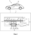
- Figure 2 is a schematic diagram of an electronic device for a vehicle according to a second non-limitative variant of a first non-limitative embodiment of the invention, said electronic device comprising a housing, a cover, at least one electronic component, an electronic support, and at least one thermal insulating pad,
- Figure 3 is a schematic diagram of an electronic device for a vehicle according to a second non-limitative embodiment of the invention, said electronic device comprising a housing, a cover, at least one electronic component, an electronic support, and at least one thermal insulating pad.
- the present invention relates to an electronic device 1 for a vehicle 2, said electronic device 1 being described in reference to figures 1 to 3 .
- the vehicle 2 is a motor vehicle.
- the motor vehicle 2 has a combustion engine, has an electric engine, or an hybrid engine.
- the electronic device 1 is a telematics control unit also referred to as TCU in the following.
- the TCU is mounted on the roof 20 of the vehicle 2 inside the vehicle 2. This non-limitative embodiment is taken as a non-limitative example in the following.
- the electronic device 2 comprises :
- the housing 10 is configured to receive said at least one component 12, the electronic support 14, the heatsink 14, and said at least one heat insulation pad 15.
- the housing 10 is of a metal material or of a thermoplastic material.
- the thermoplastic material is lighter than the metal material and the cost is reduced.
- the housing 10 is composed of two parts, an upper housing 10.1 and a lower housing 10.2.
- the lower housing 10.2 is composed of a base 10.20 and a wall 10.21 that extends perpendicular to the base 10.20.
- the upper housing 10.1 extends along the wall 10.21 of the lower housing 10.2 when the electronic device 1 is assembled.
- the lower housing 10.2 is only composed of a base.
- the upper housing 10.1 extends perpendicular to the lower housing 10.2 and is based on the lower housing 10.2 when the electronic device 1 is assembled.
- the upper housing 10.1 and the lower housing 10.2 are configured to hold the electronic support 13. In particular, they hold it along its border 13.1.
- the lower housing 10.2 is composed of the base 10.20 and a wall 10.21.
- the cover 11 is configured to close the housing 10.1. It is configured to be placed on the upper housing 10.1.
- the cover 11 is in contact with the roof 20 of the vehicle 2, in particular with a decorative part, where it can be fixed. In a non-limitative example, it is fixed with screws (not illustrated).
- the TCU is placed above the head of the passengers of the vehicle 2.
- said at least one component 12 is a TCU sensor chip 12.
- the TCU comprises only one TCU sensor chip 12. This non-limitative embodiment is taken as a non-limitative example in the following.
- the TCU sensor chip 12 is configured to receive and emit some signals (not illustrated) for the vehicle to communicate with other vehicles, with a base station or other telecommunication equipment. In non-limitative embodiments, these signals are used for semi-autonomous or autonomous driving. As, such a TCU sensor chip 12 is well-known by the person skilled in the art, it is not described here.
- the TCU sensor chip 12 generates some heat that has to be managed. It produces higher power than other electronic components inside the TCU. So it generates more heat.
- the TCU sensor chip 12 is placed on the electronic support 13, on a side 13.2 of said electronic support 13 that is opposed to the one 13.3 where the heatsink 14 is.
- the upper housing 10.1 with the cover 11 covers the TCU sensor chip 12.
- the electronic support 13 is configured to support the TCU sensor chip 12. It also supports other electronic components 12' such as in non-limitative examples wifi chip, inductor, ethernet chip, audio power amplifier, power supplier.
- the electronic support 13 is a printed circuit board assembly also referred to as PCBA in the following.
- the electronic support 13 has a border 13.1 that extends along all the perimeter of the electronic support 13. It has a top side 13.2 and a low side 13.3.
- the top side 13.2 is configured to receive the TCU sensor chip 12 and the other electronic components 12'.
- the electronic support 13 is parallel to the base 10.20 of the lower housing 10.2 when the electronic device 1 is assembled.
- the electronic support 13 is held by the upper housing 10.1 and the lower housing 10.2 along its border 13.1. It is sandwiched between the upper housing 10.1 and the lower housing 10.2. With this first non-limitative embodiment, one can have a smaller size heatsink 14 and thus one can reduce the cost and the weight of the electronic device 1.
- the electronic support 13 is held by the heatsink 14.
- its border 13.1 is placed above two legs 142 of the heatsink 14.
- the heatsink 14 is configured to cool the TCU sensor chip 12 and the electronic support 13 and the other electronic components 12' on the electronic support 13.
- the heatsink 14 comprises fins 141 that extend from a base 140, and legs 142 that extend from the base 140 and are perpendicular to the base 140.
- the fins 141 are perpendicular to the base 140.
- the fins 141 are also called cooling fins 141.
- the heat coming from the TCU sensor chip 12 flows along the fins 141 of the heatsink 14 and is extracted via the fins 14 outside the housing 10.
- the fins 141 pass through the housing 10, in particular the lower housing 10.2. It permits to take the heat generated by the TCU sensor chip 12 and the other electronic components 12' of the electronic support 13 and to output it from the housing 10. The heat is not held within the housing 10.
- the heatsink 14 is disposed on the low side 13.3 of the electronic support 13 that is opposed to the one 13.2 where the TCU sensor chip 12 is. It is disposed in regard to the TCU sensor chip 12 so that it can efficiently collect the heat coming from the TCU sensor chip 12.
- the electronic device 1 comprises one thermal insulation pad 15. In a second non-limitative embodiment, the electronic device 1 comprises two thermal insulation pad 15.
- the thermal insulation pad 15 is placed on the base 10.20 of the lower housing 10.2. In a non-limitative variant of embodiment, it is glued to the base 10.20. In another non-limitative variant of embodiment, it is fixed with two screws to the base 10.20.
- the thermal insulation pad 15 presents a circular, a rectangular, or a square form.
- the heat that comes from the TCU sensor chip 12 and that flows along the fins 141 of the heatsink 14 and that is extracted via the fins 14 outside the housing 10 can't flow back to the electronic support 14 via the lower housing 10.2, through the base 10.20 and then through the wall 10.21, as there is no more any direct contact between the lower housing 10.20 and the heatsink 14 thanks to the thermal insulation pad 15.
- the heat will not go to the electronic support 14 and it won't heat up the TCU sensor chip 12 and the other electronic components 12'.
- the heatsink 14 is isolated from the electronic support 13. It means that it has no direct contact with the electronic support 13.
- This arrangement allows cooling the TCU sensor chip 12 with the help of the thermo-electric cooler 16 described later in the following.
- the heat coming from the TCU sensor chip 12 will not heat the other electronic components 12'.
- their temperature will not be too high.
- it allows better thermal efficiency of the electronic components' temperature.
- the heatsink 14 is in direct contact with the electronic support 13. As illustrated, in particular the legs 142 of the heatsink 14 are in contact with the lower side 13.3 of the electronic support 13. It still allows a good efficiency when a lower consumption TCU sensor chip 12 is used.
- the thermal insulation pad 15 is disposed between the electronic support 13 and the heatsink 14.
- the heatsink 14 is isolated from the electronic support 13.
- two thermal insulation pads 15 are disposed each between one of the two legs 142 of the heatsink 14 and the low side 13.3 of the electronic support 13.
- the thermal insulation pads 15 are disposed at the level of the border 13.1 of the electronic support 13.
- the thermal insulation pads 15 are glued to the electronic support 13 and to the heatsink 14.
- the legs 142 comprise each one a groove where a thermal insulation pad 15 can be put inside.
- the heatsink 14 has about the same width as the width of electronic support 13. It is to be noted that its length can be chosen according to the total power dissipation of the electronic components 12 and 12'. It permits to support the electronic support 13 on the legs 142 of the heatsink 14 along its border 13.1.
- the electronic device 1 further comprises a thermo-electric cooler 16 disposed between the heatsink 14 and the electronic support 13.
- the thermo-electric cooler 16 is also referred to as TEC in the following.
- the thermo-electric cooler 16 is disposed between the base 140 of the heatsink 14 and the low side 13.3 of the electronic support 13.
- the thermo-electric cooler 16 is placed on the heatsink 14, in particular on its base 140.
- thermo-electric cooler 16 is placed on the side (here the low side 13.3) of the electronic support 14 opposed to the side (here the top side 13.2) where the TCU sensor chip 12 is placed and in regard to said TCU sensor chip 12.
- thermos-electric cooler 16 has a size slightly bigger than the TCU sensor chip 12.
- thermo-electric cooler 16 permits to enhance the extraction of the heat from the TCU sensor chip 12 and the other electronic components 12'.
- the thermo-electric cooler 16 transfers the heat in particular from the power source which is the TCU sensor chip 12 to the heatsink 14.
- a TEC requires external current to be operational whereas the heatsink 14 doesn't need any current. Cooling the TCU sensor chip 12 and the electronic components 12' using the TEC in combination with the heatsink 14 is more efficient compared to the cooling with only the heatsink 14.
- the TEC with consumption of electrical energy, brings heat from the TCU sensor 12 and the other electronic components 12' and transfers it to the heatsink 14.
- the heatsink 14 is about the same width as the thermo-electric cooler 16. The size of the heatsink 14 is reduced and thus its cost.
- the heatsink 14 has a larger width than the width of the thermo-electric cooler 16 as said heatsink 14 has about the same width as the width of the electronic support 13.
- the electronic device 1 further comprises two thermal interface materials 17, 18.
- a first thermal interface material 17 is placed between the electronic support 13 and the thermo-electric cooler 16.
- a second thermal interface material 18 is placed between the thermo-electric cooler 16 and the heatsink 14.
- a thermal interface material is also referred to as TIM in the following.
- the thermal interface materials 17, 18 permits to fill in the air gap between the electronic support 14 and the thermos-electric cooler 16, and the air gap between the thermo-electric cooler 16 and the heatsink 14 so that the heat flows with low thermal resistance. The heat will flow easily. Thanks to the TIMs, the thermal resistance between one element and another one is reduced (between the electronic support 13 and the thermo-electric cooler 16, and between the thermo-electric cooler 16 and the heatsink 14).
- thermo interface materials 17, 18 eases the transmission of the heat from the electronic support 13 to the thermo-electric cooler 16, and from the thermo-electric cooler 16 to the heatsink 14. It is to be noted that the TIMs also avoid short-circuit between the electronic support 13 and the thermo-electric cooler 16 as they are not in direct contact altogether.
- thermo-electric cooler 16 with high capacity that needs a high current consumption to help the heatsink 14 to cool the TCU sensor chip 12 and the electronic support 13 with the other electronic components 12'.
- the electronic device 1 is an electronic device used for computers or any other applications different from the automotive application.
- some embodiments of the invention may comprise one or a plurality of the following advantages:
Landscapes
- Physics & Mathematics (AREA)
- Thermal Sciences (AREA)
- Engineering & Computer Science (AREA)
- Microelectronics & Electronic Packaging (AREA)
- Cooling Or The Like Of Electrical Apparatus (AREA)
Abstract
The invention relates to an electronic device (1) for a vehicle (2), said electronic device comprising:
- a housing (10),
- a cover (11) that is configured to close said housing (10),
- at least one electronic component (12),
- an electronic support (13) that is configured to support said at least one electronic component (12),
- a heatsink (14) that is configured to cool said at least one electronic component (12),
wherein said electronic device (1) further comprises at least one thermal insulation pad (15) that is configured to prevent heat generated by said at least one electronic component (12) to flow back from said heatsink (14) to said electronic support (13).
- a housing (10),
- a cover (11) that is configured to close said housing (10),
- at least one electronic component (12),
- an electronic support (13) that is configured to support said at least one electronic component (12),
- a heatsink (14) that is configured to cool said at least one electronic component (12),
wherein said electronic device (1) further comprises at least one thermal insulation pad (15) that is configured to prevent heat generated by said at least one electronic component (12) to flow back from said heatsink (14) to said electronic support (13).
Description
- The present invention relates to an electronic device for a vehicle. Such electronic device, may be used, but not exclusively, in the automotive domain and in particular for telematics control.
- In the automotive domain, an electronic device for a vehicle that is used for telematics control, well-known by the person skilled in the art, comprises:
- a housing,
- a cover that is configured to close said housing,
- at least one electronic component,
- an electronic support that is configured to support said electronic component and that is disposed within the housing,
- a heatsink that is configured to cool said electronic component and that is disposed within the housing.
- In the telematics control application, the at least one electronic component is a TCU sensor chip. The heatsink has two legs on which the electronic support is disposed on. Therefore, it is in contact with the electronic support. The heatsink is placed below the electronic support and has a base that extends along the whole surface of the electronic support. It has about the same size than the electronic support.
- The housing is configured to receive the TCU sensor chip, the electronic support and the heatsink. These three elements are placed inside the housing.
- One problem of this prior art is that during the operation of cooling, after some period of time the heatsink will heat back the TCU sensor chip and other electronic components on the electronic support as the heat generated by said TCU sensor chip and other electronic components flows back from the heatsink to the electronic support through the two points of contact that are formed by the legs of the heatsink. Thus, the temperature of the TCU sensor chip and the electronic support will further increase after some time despite the cooling.
- It is an object of the invention to provide an electronic device for a vehicle, which resolves the problem above-stated.
- To this end, it is provided an electronic device for a vehicle , said electronic device comprising :
- a housing,
- a cover that is configured to close said housing,
- at least one electronic component,
- an electronic support that is configured to support said at least one electronic component,
- a heatsink that is configured to cool said at least one electronic component,
- As we will see in further details, the thermal insulation pad permits to cut off the thermal bridge between the heatsink and the electronic support and in particular the TCU sensor chip so that no heat flows back to said TCU sensor chip and said electronic support.
- According to non-limitative embodiments of the invention, the electronic device for a vehicle further comprises the following characteristics.
- In a non-limitative embodiment, said at least one thermal insulation pad (16) is disposed between said heatsink (14) and said housing.
- In a non-limitative embodiment, said heatsink is isolated from said electronic support or is in direct contact with said electronic support.
- In a non-limitative embodiment, said at least one thermal insulation pad is disposed between said electronic support and said heatsink.
- In a non-limitative embodiment, said heatsink is about the same width as said electronic support.
- In a non-limitative embodiment, said electronic device further comprises a thermo-electric cooler disposed between said heatsink and said electronic support.
- In a non-limitative embodiment, said heatsink is about the same width as said thermo-electric cooler.
- In a non-limitative embodiment, said thermo-electric cooler has a width that is larger than the width of the thermo-electric cooler.
- In a non-limitative embodiment, said electronic device further comprises two thermal interface materials that are respectively placed between said electronic support and said thermo-electric cooler, and between said thermo-electric cooler and said heatsink.
- In a non-limitative embodiment, said heatsink comprises fins that extend from a base and pass through said housing.
- In a non-limitative embodiment, said housing is of a metal material or of a thermoplastic material.
- In a non-limitative embodiment, said at least one electronic component is a TCU sensor chip.
- In a non-limitative embodiment, said electronic device is a telematics control unit.
- In a non-limitative embodiment, only one thermal insulation pad is disposed between said heatsink and said housing.
- In a non-limitative embodiment, two thermal insulation pads are disposed between said electronic support and said heatsink.
- In a non-limitative embodiment, said housing is composed of an upper housing and a lower housing.
- In a non-limitative embodiment, said heatsink is composed of a base and of two legs.
- In a non-limitative embodiment, said thermal insulation pad is disposed between the base of said heatsink and the base of said lower housing.
- In a non-limitative embodiment, the electronic support has a top side and low side opposed to the top side.
- In a non-limitative embodiment, the legs of the heatsink are in contact with the low side of the electronic support.
- In a non-limitative embodiment, two thermal insulation pads are disposed each between one of the two legs of said heatsink and the low side of said electronic support.
- In a non-limitative embodiment, the thermo-electric cooler is disposed between the base of said heatsink and the low side of said electronic support.
- In a non-limitative embodiment, the thermo-electric cooler is placed on the side of the electronic support opposed to the side where the at least one electronic component is placed and in regard to said TCU sensor chip.
- In a non-limitative embodiment, the thermos-electric cooler has a size slightly bigger than at least one electronic component.
- In a non-limitative embodiment, the fins of said heatsink pass through the lower housing.
- In a non-limitative embodiment, the electronic device comprises a plurality of electronic components.
- Some embodiments of methods and/or system in accordance with embodiments of the present invention are now described, by way of example only, and with reference to the accompanying drawings, in which:
-
Figure 1 is a schematic diagram of an electronic device for a vehicle according to a first non-limitative variant of a first non-limitative embodiment of the invention, said electronic device comprising a housing, a cover, at least one electronic component, an electronic support, and at least one thermal insulating pad, -
Figure 2 is a schematic diagram of an electronic device for a vehicle according to a second non-limitative variant of a first non-limitative embodiment of the invention, said electronic device comprising a housing, a cover, at least one electronic component, an electronic support, and at least one thermal insulating pad, -
Figure 3 is a schematic diagram of an electronic device for a vehicle according to a second non-limitative embodiment of the invention, said electronic device comprising a housing, a cover, at least one electronic component, an electronic support, and at least one thermal insulating pad. - In the following description, well-known functions or constructions by the person skilled in the art are not described in detail since they would obscure the invention in unnecessary detail.
- The present invention relates to an electronic device 1 for a vehicle 2, said electronic device 1 being described in reference to
figures 1 to 3 . In a non-limitative embodiment, the vehicle 2 is a motor vehicle. In non-limitative variants of embodiment, the motor vehicle 2 has a combustion engine, has an electric engine, or an hybrid engine. - In a non-limitative embodiment, the electronic device 1 is a telematics control unit also referred to as TCU in the following. In a non-limitative embodiment, the TCU is mounted on the
roof 20 of the vehicle 2 inside the vehicle 2. This non-limitative embodiment is taken as a non-limitative example in the following. - As illustrated in
figures 1 to 3 , the electronic device 2 comprises : - a
housing 10, - a
cover 11, - at least one
electronic component 12, - an
electronic support 13, - a
heatsink 14, - at least one
heat insulation pad 15. - These different elements are described in detail hereinafter.
- The
housing 10 is configured to receive said at least onecomponent 12, theelectronic support 14, theheatsink 14, and said at least oneheat insulation pad 15. - In non-limitative embodiments, the
housing 10 is of a metal material or of a thermoplastic material. The thermoplastic material is lighter than the metal material and the cost is reduced. - In a non-limitative embodiment, the
housing 10 is composed of two parts, an upper housing 10.1 and a lower housing 10.2. - In a first non-limitative embodiment illustrated in
figures 1 and2 , the lower housing 10.2 is composed of a base 10.20 and a wall 10.21 that extends perpendicular to the base 10.20. The upper housing 10.1 extends along the wall 10.21 of the lower housing 10.2 when the electronic device 1 is assembled. - In a second non-limitative embodiment illustrated in
figure 3 , the lower housing 10.2 is only composed of a base. The upper housing 10.1 extends perpendicular to the lower housing 10.2 and is based on the lower housing 10.2 when the electronic device 1 is assembled. - In a first non-limitative embodiment illustrated in
figures 1 and2 , the upper housing 10.1 and the lower housing 10.2 are configured to hold theelectronic support 13. In particular, they hold it along its border 13.1. In this case, the lower housing 10.2 is composed of the base 10.20 and a wall 10.21. - Its wall 10.21 and the upper housing 10.2 held the
electronic support 13. - The
cover 11 is configured to close the housing 10.1. It is configured to be placed on the upper housing 10.1. - The
cover 11 is in contact with theroof 20 of the vehicle 2, in particular with a decorative part, where it can be fixed. In a non-limitative example, it is fixed with screws (not illustrated). - Hence, in a non-limitative example, the TCU is placed above the head of the passengers of the vehicle 2.
- In a non-limitative embodiment, said at least one
component 12 is aTCU sensor chip 12. - In a non-limitative embodiment, the TCU comprises only one
TCU sensor chip 12. This non-limitative embodiment is taken as a non-limitative example in the following. - The
TCU sensor chip 12 is configured to receive and emit some signals (not illustrated) for the vehicle to communicate with other vehicles, with a base station or other telecommunication equipment. In non-limitative embodiments, these signals are used for semi-autonomous or autonomous driving. As, such aTCU sensor chip 12 is well-known by the person skilled in the art, it is not described here. - The
TCU sensor chip 12 generates some heat that has to be managed. It produces higher power than other electronic components inside the TCU. So it generates more heat. TheTCU sensor chip 12 is placed on theelectronic support 13, on a side 13.2 of saidelectronic support 13 that is opposed to the one 13.3 where theheatsink 14 is. - The upper housing 10.1 with the
cover 11 covers theTCU sensor chip 12. - The
electronic support 13 is configured to support theTCU sensor chip 12. It also supports other electronic components 12' such as in non-limitative examples wifi chip, inductor, ethernet chip, audio power amplifier, power supplier. - In a non-limitative embodiment, the
electronic support 13 is a printed circuit board assembly also referred to as PCBA in the following. Theelectronic support 13 has a border 13.1 that extends along all the perimeter of theelectronic support 13. It has a top side 13.2 and a low side 13.3. The top side 13.2 is configured to receive theTCU sensor chip 12 and the other electronic components 12'. - The
electronic support 13 is parallel to the base 10.20 of the lower housing 10.2 when the electronic device 1 is assembled. - In a first non-limitative embodiment illustrated in
figures 1 and2 , theelectronic support 13 is held by the upper housing 10.1 and the lower housing 10.2 along its border 13.1. It is sandwiched between the upper housing 10.1 and the lower housing 10.2. With this first non-limitative embodiment, one can have asmaller size heatsink 14 and thus one can reduce the cost and the weight of the electronic device 1. - In a second non-limitative embodiment illustrated in
figure 3 , theelectronic support 13 is held by theheatsink 14. In particular, its border 13.1 is placed above twolegs 142 of theheatsink 14. - The
heatsink 14 is configured to cool theTCU sensor chip 12 and theelectronic support 13 and the other electronic components 12' on theelectronic support 13. To this end, theheatsink 14 comprisesfins 141 that extend from abase 140, andlegs 142 that extend from thebase 140 and are perpendicular to thebase 140. In a non-limitative embodiment, thefins 141 are perpendicular to thebase 140. Thefins 141 are also called coolingfins 141. - The heat coming from the
TCU sensor chip 12 flows along thefins 141 of theheatsink 14 and is extracted via thefins 14 outside thehousing 10. - In a non-limitative embodiment, the
fins 141 pass through thehousing 10, in particular the lower housing 10.2. It permits to take the heat generated by theTCU sensor chip 12 and the other electronic components 12' of theelectronic support 13 and to output it from thehousing 10. The heat is not held within thehousing 10. - The
heatsink 14 is disposed on the low side 13.3 of theelectronic support 13 that is opposed to the one 13.2 where theTCU sensor chip 12 is. It is disposed in regard to theTCU sensor chip 12 so that it can efficiently collect the heat coming from theTCU sensor chip 12. - The at least one
thermal insulation pad 15 is configured to prevent the heat generated in particular by theTCU sensor chip 12 to flow back from theheatsink 14 to theelectronic support 13 and therefore it prevents the heating up of theelectronic support 13, theTCU sensor chip 12 and the other electronic components 12'. In non-limitative embodiment, thethermal insulation pad 15 is of polymer material, or of plastic material, or of polyutherane material, or of fiber glass reinforced material. The material of thethermal insulation pad 15 is chosen in such a way that it is not thermally conductive to avoid heat flow. In a non-limitative embodiment, the material has a thermal conductivity inferior to 0.1W/m.K (Watt per meter Kelvin). A thermal conductivity closed to zero will not allow heat to transfer from theheatsink 14 to theelectronic support 13. - In a first non-limitative embodiment, the electronic device 1 comprises one
thermal insulation pad 15. In a second non-limitative embodiment, the electronic device 1 comprises twothermal insulation pad 15. - In a first non-limitative embodiment illustrated in
figures 1 and2 , thethermal insulation pad 15 is disposed between theheatsink 14 and thehousing 10. There is only onethermal insulation pad 15. In particular, it is disposed between the base 140 of the heatsink and the base 10.20 of the lower housing 10.2. - In a first non-limitative embodiment, the
thermal insulation pad 15 is placed on the base 10.20 of the lower housing 10.2. In a non-limitative variant of embodiment, it is glued to the base 10.20. In another non-limitative variant of embodiment, it is fixed with two screws to the base 10.20. - In a second non-limitative embodiment, the lower housing 10.2 comprises a groove (not illustrated) where the
thermal insulation pad 15 can be put inside. In particular the base 10.20 of the lower housing 10.2 comprises the groove. - On top view (not illustrated), in non-limitative embodiments, the
thermal insulation pad 15 presents a circular, a rectangular, or a square form. - With the
thermal insulation pad 15, the heat that comes from theTCU sensor chip 12 and that flows along thefins 141 of theheatsink 14 and that is extracted via thefins 14 outside thehousing 10 can't flow back to theelectronic support 14 via the lower housing 10.2, through the base 10.20 and then through the wall 10.21, as there is no more any direct contact between the lower housing 10.20 and theheatsink 14 thanks to thethermal insulation pad 15. The heat will not go to theelectronic support 14 and it won't heat up theTCU sensor chip 12 and the other electronic components 12'. - In a first non-limitative variant of embodiment illustrated in
figure 1 , theheatsink 14 is isolated from theelectronic support 13. It means that it has no direct contact with theelectronic support 13. This arrangement allows cooling theTCU sensor chip 12 with the help of the thermo-electric cooler 16 described later in the following. Thus, the heat coming from theTCU sensor chip 12 will not heat the other electronic components 12'. Thus, their temperature will not be too high. Hence, it allows better thermal efficiency of the electronic components' temperature. - In a second non-limitative variant of embodiment illustrated in
figure 2 , theheatsink 14 is in direct contact with theelectronic support 13. As illustrated, in particular thelegs 142 of theheatsink 14 are in contact with the lower side 13.3 of theelectronic support 13. It still allows a good efficiency when a lower consumptionTCU sensor chip 12 is used. - In a second non-limitative embodiment illustrated in
figure 3 , thethermal insulation pad 15 is disposed between theelectronic support 13 and theheatsink 14. Hence, theheatsink 14 is isolated from theelectronic support 13. In particular, twothermal insulation pads 15 are disposed each between one of the twolegs 142 of theheatsink 14 and the low side 13.3 of theelectronic support 13. As we can see, thethermal insulation pads 15 are disposed at the level of the border 13.1 of theelectronic support 13. In this case, in a first non-limitative embodiment, thethermal insulation pads 15 are glued to theelectronic support 13 and to theheatsink 14. In a second non-limitative embodiment (not illustrated), thelegs 142 comprise each one a groove where athermal insulation pad 15 can be put inside. - As the
heatsink 14 is not in contact with theelectronic support 13, i.e. it is isolated from theelectronic support 13, the heat that is coming from theTCU sensor chip 12 and that flows along thefins 141 of theheatsink 14 and that is extracted via thefins 14 outside thehousing 10 can't flow back to theelectronic support 14 via theheatsink 14, and in particular via thelegs 142. - In a non-limitative embodiment illustrated in
figure 3 , theheatsink 14 has about the same width as the width ofelectronic support 13. It is to be noted that its length can be chosen according to the total power dissipation of theelectronic components 12 and 12'. It permits to support theelectronic support 13 on thelegs 142 of theheatsink 14 along its border 13.1. - In a non-limitative embodiment illustrated in
figures 1 to 3 , the electronic device 1 further comprises a thermo-electric cooler 16 disposed between theheatsink 14 and theelectronic support 13. The thermo-electric cooler 16 is also referred to as TEC in the following. In particular, the thermo-electric cooler 16 is disposed between the base 140 of theheatsink 14 and the low side 13.3 of theelectronic support 13. The thermo-electric cooler 16 is placed on theheatsink 14, in particular on itsbase 140. - In a non-limitative embodiment, the thermo-
electric cooler 16 is placed on the side (here the low side 13.3) of theelectronic support 14 opposed to the side (here the top side 13.2) where theTCU sensor chip 12 is placed and in regard to saidTCU sensor chip 12. In a non-limitative embodiment, the thermos-electric cooler 16 has a size slightly bigger than theTCU sensor chip 12. - As it is placed opposite to the
TCU sensor chip 12 and its size is slightly bigger, the thermo-electric cooler 16 permits to enhance the extraction of the heat from theTCU sensor chip 12 and the other electronic components 12'. The thermo-electric cooler 16 transfers the heat in particular from the power source which is theTCU sensor chip 12 to theheatsink 14. It is to be noted that a TEC requires external current to be operational whereas theheatsink 14 doesn't need any current. Cooling theTCU sensor chip 12 and the electronic components 12' using the TEC in combination with theheatsink 14 is more efficient compared to the cooling with only theheatsink 14. The TEC, with consumption of electrical energy, brings heat from theTCU sensor 12 and the other electronic components 12' and transfers it to theheatsink 14. - In a first non-limitative embodiment illustrated in
figure 1 and2 , theheatsink 14 is about the same width as the thermo-electric cooler 16. The size of theheatsink 14 is reduced and thus its cost. - In a second non-limitative embodiment illustrated in
figure 3 , theheatsink 14 has a larger width than the width of the thermo-electric cooler 16 as saidheatsink 14 has about the same width as the width of theelectronic support 13. - In a non-limitative embodiment, the electronic device 1 further comprises two
thermal interface materials thermal interface material 17 is placed between theelectronic support 13 and the thermo-electric cooler 16. A secondthermal interface material 18 is placed between the thermo-electric cooler 16 and theheatsink 14. A thermal interface material is also referred to as TIM in the following. Thethermal interface materials electronic support 14 and the thermos-electric cooler 16, and the air gap between the thermo-electric cooler 16 and theheatsink 14 so that the heat flows with low thermal resistance. The heat will flow easily. Thanks to the TIMs, the thermal resistance between one element and another one is reduced (between theelectronic support 13 and the thermo-electric cooler 16, and between the thermo-electric cooler 16 and the heatsink 14). It means that there is less temperature difference between one element to another one. Therefore, the use of thethermal interface materials electronic support 13 to the thermo-electric cooler 16, and from the thermo-electric cooler 16 to theheatsink 14. It is to be noted that the TIMs also avoid short-circuit between theelectronic support 13 and the thermo-electric cooler 16 as they are not in direct contact altogether. - It is to be noted that as the
fins 141 of theheatsink 14 pass through the lower housing 10.2, the heat can flow outside thehousing 10. Therefore, there is no need to have a thermo-electric cooler 16 with high capacity that needs a high current consumption to help theheatsink 14 to cool theTCU sensor chip 12 and theelectronic support 13 with the other electronic components 12'. - It is to be understood that the present invention is not limited to the aforementioned embodiments and variations and modifications may be made without departing from the scope of the invention. All statements herein reciting principles, aspects, and embodiments of the invention, as well as specific examples thereof, are intended to encompass equivalents thereof. In this respect, the following remarks are made. Hence, in another non-limitative application, the electronic device 1 is an electronic device used for computers or any other applications different from the automotive application.
- Hence, some embodiments of the invention may comprise one or a plurality of the following advantages:
- it permits to avoid a flowing back of the heat to the
TCU sensor chip 12 and to theelectronic support 13 with the other electronic components 12', and thus it avoids heating up theTCU sensor chip 12 and theelectronic support 13 with the other components 12', - the electronic device 1 is thermally safer than the solution of the prior art, and for longer duration,
- thanks to the
fins 141 that passes through thehousing 10, the heat can go out from the housing even if the space is limited within thehousing 10, contrary to the prior art where the heat can't go out the housing and the heat stays inside thehousing 10.
Claims (13)
- Electronic device (1) for a vehicle (2), said electronic device comprising :- a housing (10),- a cover (11) that is configured to close said housing (10),- at least one electronic component (12),- an electronic support (13) that is configured to support said at least one electronic component (12),- a heatsink (14) that is configured to cool said at least one electronic component (12),wherein said electronic device (1) further comprises at least one thermal insulation pad (15) that is configured to prevent heat generated by said at least one electronic component (12) to flow back from said heatsink (14) to said electronic support (13).
- Electronic device (1) according to claim 1, wherein said at least one thermal insulation pad (16) is disposed between said heatsink (14) and said housing (10.2).
- Electronic device (1) according to the preceding claim, wherein said heatsink (14) is isolated from said electronic support (13) or is in direct contact with said electronic support (13).
- Electronic device (1) according to claim 1, wherein said at least one thermal insulation pad (16) is disposed between said electronic support (13) and said heatsink (14).
- Electronic device (1) according to any of the preceding claim, wherein said heatsink (14) is about the same width as said electronic support (13).
- Electronic device (1) according to any of the preceding claims, wherein said electronic device (1) further comprises a thermo-electric cooler (16) disposed between said heatsink (14) and said electronic support (13).
- Electronic device (1) according to any of the preceding claims 2 or 3 combined with claim 6, wherein said heatsink (14) is about the same width as said thermo-electric cooler (16).
- Electronic device (1) according to any of the preceding claims 4 or 5 combined with claim 6, wherein said thermo-electric cooler (16) has a width that is larger than the width of the thermo-electric cooler (16).
- Electronic device (1) according to any of the preceding claims 6 to 8, wherein said electronic device (1) further comprises two thermal interface materials (17, 18) that are respectively placed between said electronic support (13) and said thermo-electric cooler (17), and between said thermo-electric cooler (16) and said heatsink (14).
- Electronic device (1) according to any of the preceding claims, wherein said heatsink (14) comprises fins (141) that extend from a base (140) and pass through said housing (10).
- Electronic device (1) according to any of the preceding claims, wherein said housing (10) is of a metal material or of a thermoplastic material.
- Electronic device (1) according to any of the preceding claims, wherein said at least one electronic component (12) is a TCU sensor chip.
- Electronic device (1) according to any of the preceding claims, wherein said electronic device is a telematics control unit.
Priority Applications (1)
| Application Number | Priority Date | Filing Date | Title |
|---|---|---|---|
| EP23193988.5A EP4518598A1 (en) | 2023-08-29 | 2023-08-29 | Electronic device for a vehicle comprising a thermal insulation pad |
Applications Claiming Priority (1)
| Application Number | Priority Date | Filing Date | Title |
|---|---|---|---|
| EP23193988.5A EP4518598A1 (en) | 2023-08-29 | 2023-08-29 | Electronic device for a vehicle comprising a thermal insulation pad |
Publications (1)
| Publication Number | Publication Date |
|---|---|
| EP4518598A1 true EP4518598A1 (en) | 2025-03-05 |
Family
ID=87971842
Family Applications (1)
| Application Number | Title | Priority Date | Filing Date |
|---|---|---|---|
| EP23193988.5A Pending EP4518598A1 (en) | 2023-08-29 | 2023-08-29 | Electronic device for a vehicle comprising a thermal insulation pad |
Country Status (1)
| Country | Link |
|---|---|
| EP (1) | EP4518598A1 (en) |
Citations (5)
| Publication number | Priority date | Publication date | Assignee | Title |
|---|---|---|---|---|
| EP1176706B1 (en) * | 2000-07-26 | 2004-12-15 | Lenze Drive Systems GmbH | Frequency converter with a housing consisting in an upper part and a lower part |
| JP2013251319A (en) * | 2012-05-30 | 2013-12-12 | Mitsubishi Electric Corp | Outdoor installation device and inverter device |
| FR3105713A1 (en) * | 2019-12-24 | 2021-06-25 | Valeo Systemes De Controle Moteur | Heat dissipation device, electrical system comprising such a device and associated manufacturing method |
| WO2022128239A1 (en) * | 2020-12-17 | 2022-06-23 | Valeo Comfort And Driving Assistance | Electronic assembly |
| WO2023110156A1 (en) * | 2021-12-15 | 2023-06-22 | Valeo Comfort And Driving Assistance | Electronic assembly |
-
2023
- 2023-08-29 EP EP23193988.5A patent/EP4518598A1/en active Pending
Patent Citations (5)
| Publication number | Priority date | Publication date | Assignee | Title |
|---|---|---|---|---|
| EP1176706B1 (en) * | 2000-07-26 | 2004-12-15 | Lenze Drive Systems GmbH | Frequency converter with a housing consisting in an upper part and a lower part |
| JP2013251319A (en) * | 2012-05-30 | 2013-12-12 | Mitsubishi Electric Corp | Outdoor installation device and inverter device |
| FR3105713A1 (en) * | 2019-12-24 | 2021-06-25 | Valeo Systemes De Controle Moteur | Heat dissipation device, electrical system comprising such a device and associated manufacturing method |
| WO2022128239A1 (en) * | 2020-12-17 | 2022-06-23 | Valeo Comfort And Driving Assistance | Electronic assembly |
| WO2023110156A1 (en) * | 2021-12-15 | 2023-06-22 | Valeo Comfort And Driving Assistance | Electronic assembly |
Similar Documents
| Publication | Publication Date | Title |
|---|---|---|
| US6875962B2 (en) | Electric heating system for a motor vehicle | |
| JP4231626B2 (en) | Motor drive device for automobile | |
| KR101968852B1 (en) | Mechanically integrated rotating electric machine device | |
| CN104956539B (en) | Thermoelectric based thermal management system | |
| US7295433B2 (en) | Electronics assembly having multiple side cooling and method | |
| KR102786035B1 (en) | Vehicles, and power conversion devices for vehicles | |
| JP6632524B2 (en) | Electric circuit for controlling load and method of manufacturing electric circuit for controlling load | |
| CN102007672B (en) | Frequency inverter being mounted on a motor | |
| GB2449143A (en) | Electronic circuit modules cooling | |
| CN104144807B (en) | The device of electrical heating fluid, relevant heating and/or the apparatus of air conditioning | |
| JP2020184847A (en) | Power conversion device | |
| WO2021053975A1 (en) | Power converter and motor-integrated power converter | |
| US7902957B2 (en) | Phase change cooled electrical resistor | |
| JP6458131B2 (en) | Air conditioner outdoor unit | |
| US20180269371A1 (en) | Cooling Arrangement For An Electronic Component | |
| CN104040865A (en) | power conversion device | |
| US20010052518A1 (en) | Air heater | |
| JP2004072959A (en) | Power converter | |
| JP2000058746A (en) | Module cooling device | |
| EP4518598A1 (en) | Electronic device for a vehicle comprising a thermal insulation pad | |
| JP4491492B2 (en) | Motor drive device for automobile | |
| WO2020080248A1 (en) | Circuit structure and electrical junction box | |
| KR102063726B1 (en) | Motor integrated inverter package and All-in-one inverter applied to the same | |
| JP2002010624A (en) | Power supply | |
| JP2001230584A (en) | Cooling method for printed circuit board mounted parts using thermoelectric cooling element |
Legal Events
| Date | Code | Title | Description |
|---|---|---|---|
| PUAI | Public reference made under article 153(3) epc to a published international application that has entered the european phase |
Free format text: ORIGINAL CODE: 0009012 |
|
| STAA | Information on the status of an ep patent application or granted ep patent |
Free format text: STATUS: THE APPLICATION HAS BEEN PUBLISHED |
|
| AK | Designated contracting states |
Kind code of ref document: A1 Designated state(s): AL AT BE BG CH CY CZ DE DK EE ES FI FR GB GR HR HU IE IS IT LI LT LU LV MC ME MK MT NL NO PL PT RO RS SE SI SK SM TR |
|
| STAA | Information on the status of an ep patent application or granted ep patent |
Free format text: STATUS: REQUEST FOR EXAMINATION WAS MADE |
|
| 17P | Request for examination filed |
Effective date: 20250801 |