EP4518002A2 - Vernetzte siloxandispersionsseparator - Google Patents
Vernetzte siloxandispersionsseparator Download PDFInfo
- Publication number
- EP4518002A2 EP4518002A2 EP24217738.4A EP24217738A EP4518002A2 EP 4518002 A2 EP4518002 A2 EP 4518002A2 EP 24217738 A EP24217738 A EP 24217738A EP 4518002 A2 EP4518002 A2 EP 4518002A2
- Authority
- EP
- European Patent Office
- Prior art keywords
- separator
- battery
- silane
- polyolefin
- weight
- Prior art date
- Legal status (The legal status is an assumption and is not a legal conclusion. Google has not performed a legal analysis and makes no representation as to the accuracy of the status listed.)
- Pending
Links
Images




Classifications
-
- H—ELECTRICITY
- H01—ELECTRIC ELEMENTS
- H01M—PROCESSES OR MEANS, e.g. BATTERIES, FOR THE DIRECT CONVERSION OF CHEMICAL ENERGY INTO ELECTRICAL ENERGY
- H01M10/00—Secondary cells; Manufacture thereof
- H01M10/05—Accumulators with non-aqueous electrolyte
- H01M10/052—Li-accumulators
-
- H—ELECTRICITY
- H01—ELECTRIC ELEMENTS
- H01M—PROCESSES OR MEANS, e.g. BATTERIES, FOR THE DIRECT CONVERSION OF CHEMICAL ENERGY INTO ELECTRICAL ENERGY
- H01M10/00—Secondary cells; Manufacture thereof
- H01M10/05—Accumulators with non-aqueous electrolyte
- H01M10/052—Li-accumulators
- H01M10/0525—Rocking-chair batteries, i.e. batteries with lithium insertion or intercalation in both electrodes; Lithium-ion batteries
-
- H—ELECTRICITY
- H01—ELECTRIC ELEMENTS
- H01M—PROCESSES OR MEANS, e.g. BATTERIES, FOR THE DIRECT CONVERSION OF CHEMICAL ENERGY INTO ELECTRICAL ENERGY
- H01M10/00—Secondary cells; Manufacture thereof
- H01M10/05—Accumulators with non-aqueous electrolyte
- H01M10/056—Accumulators with non-aqueous electrolyte characterised by the materials used as electrolytes, e.g. mixed inorganic/organic electrolytes
- H01M10/0564—Accumulators with non-aqueous electrolyte characterised by the materials used as electrolytes, e.g. mixed inorganic/organic electrolytes the electrolyte being constituted of organic materials only
- H01M10/0566—Liquid materials
- H01M10/0568—Liquid materials characterised by the solutes
-
- H—ELECTRICITY
- H01—ELECTRIC ELEMENTS
- H01M—PROCESSES OR MEANS, e.g. BATTERIES, FOR THE DIRECT CONVERSION OF CHEMICAL ENERGY INTO ELECTRICAL ENERGY
- H01M10/00—Secondary cells; Manufacture thereof
- H01M10/05—Accumulators with non-aqueous electrolyte
- H01M10/056—Accumulators with non-aqueous electrolyte characterised by the materials used as electrolytes, e.g. mixed inorganic/organic electrolytes
- H01M10/0564—Accumulators with non-aqueous electrolyte characterised by the materials used as electrolytes, e.g. mixed inorganic/organic electrolytes the electrolyte being constituted of organic materials only
- H01M10/0566—Liquid materials
- H01M10/0569—Liquid materials characterised by the solvents
-
- H—ELECTRICITY
- H01—ELECTRIC ELEMENTS
- H01M—PROCESSES OR MEANS, e.g. BATTERIES, FOR THE DIRECT CONVERSION OF CHEMICAL ENERGY INTO ELECTRICAL ENERGY
- H01M4/00—Electrodes
- H01M4/02—Electrodes composed of, or comprising, active material
- H01M4/36—Selection of substances as active materials, active masses, active liquids
- H01M4/38—Selection of substances as active materials, active masses, active liquids of elements or alloys
-
- H—ELECTRICITY
- H01—ELECTRIC ELEMENTS
- H01M—PROCESSES OR MEANS, e.g. BATTERIES, FOR THE DIRECT CONVERSION OF CHEMICAL ENERGY INTO ELECTRICAL ENERGY
- H01M4/00—Electrodes
- H01M4/02—Electrodes composed of, or comprising, active material
- H01M4/36—Selection of substances as active materials, active masses, active liquids
- H01M4/38—Selection of substances as active materials, active masses, active liquids of elements or alloys
- H01M4/386—Silicon or alloys based on silicon
-
- H—ELECTRICITY
- H01—ELECTRIC ELEMENTS
- H01M—PROCESSES OR MEANS, e.g. BATTERIES, FOR THE DIRECT CONVERSION OF CHEMICAL ENERGY INTO ELECTRICAL ENERGY
- H01M4/00—Electrodes
- H01M4/02—Electrodes composed of, or comprising, active material
- H01M4/36—Selection of substances as active materials, active masses, active liquids
- H01M4/48—Selection of substances as active materials, active masses, active liquids of inorganic oxides or hydroxides
- H01M4/50—Selection of substances as active materials, active masses, active liquids of inorganic oxides or hydroxides of manganese
- H01M4/505—Selection of substances as active materials, active masses, active liquids of inorganic oxides or hydroxides of manganese of mixed oxides or hydroxides containing manganese for inserting or intercalating light metals, e.g. LiMn2O4 or LiMn2OxFy
-
- H—ELECTRICITY
- H01—ELECTRIC ELEMENTS
- H01M—PROCESSES OR MEANS, e.g. BATTERIES, FOR THE DIRECT CONVERSION OF CHEMICAL ENERGY INTO ELECTRICAL ENERGY
- H01M4/00—Electrodes
- H01M4/02—Electrodes composed of, or comprising, active material
- H01M4/36—Selection of substances as active materials, active masses, active liquids
- H01M4/48—Selection of substances as active materials, active masses, active liquids of inorganic oxides or hydroxides
- H01M4/52—Selection of substances as active materials, active masses, active liquids of inorganic oxides or hydroxides of nickel, cobalt or iron
- H01M4/525—Selection of substances as active materials, active masses, active liquids of inorganic oxides or hydroxides of nickel, cobalt or iron of mixed oxides or hydroxides containing iron, cobalt or nickel for inserting or intercalating light metals, e.g. LiNiO2, LiCoO2 or LiCoOxFy
-
- H—ELECTRICITY
- H01—ELECTRIC ELEMENTS
- H01M—PROCESSES OR MEANS, e.g. BATTERIES, FOR THE DIRECT CONVERSION OF CHEMICAL ENERGY INTO ELECTRICAL ENERGY
- H01M50/00—Constructional details or processes of manufacture of the non-active parts of electrochemical cells other than fuel cells, e.g. hybrid cells
- H01M50/40—Separators; Membranes; Diaphragms; Spacing elements inside cells
- H01M50/403—Manufacturing processes of separators, membranes or diaphragms
-
- H—ELECTRICITY
- H01—ELECTRIC ELEMENTS
- H01M—PROCESSES OR MEANS, e.g. BATTERIES, FOR THE DIRECT CONVERSION OF CHEMICAL ENERGY INTO ELECTRICAL ENERGY
- H01M50/00—Constructional details or processes of manufacture of the non-active parts of electrochemical cells other than fuel cells, e.g. hybrid cells
- H01M50/40—Separators; Membranes; Diaphragms; Spacing elements inside cells
- H01M50/403—Manufacturing processes of separators, membranes or diaphragms
- H01M50/406—Moulding; Embossing; Cutting
-
- H—ELECTRICITY
- H01—ELECTRIC ELEMENTS
- H01M—PROCESSES OR MEANS, e.g. BATTERIES, FOR THE DIRECT CONVERSION OF CHEMICAL ENERGY INTO ELECTRICAL ENERGY
- H01M50/00—Constructional details or processes of manufacture of the non-active parts of electrochemical cells other than fuel cells, e.g. hybrid cells
- H01M50/40—Separators; Membranes; Diaphragms; Spacing elements inside cells
- H01M50/409—Separators, membranes or diaphragms characterised by the material
-
- H—ELECTRICITY
- H01—ELECTRIC ELEMENTS
- H01M—PROCESSES OR MEANS, e.g. BATTERIES, FOR THE DIRECT CONVERSION OF CHEMICAL ENERGY INTO ELECTRICAL ENERGY
- H01M50/00—Constructional details or processes of manufacture of the non-active parts of electrochemical cells other than fuel cells, e.g. hybrid cells
- H01M50/40—Separators; Membranes; Diaphragms; Spacing elements inside cells
- H01M50/409—Separators, membranes or diaphragms characterised by the material
- H01M50/411—Organic material
- H01M50/414—Synthetic resins, e.g. thermoplastics or thermosetting resins
-
- H—ELECTRICITY
- H01—ELECTRIC ELEMENTS
- H01M—PROCESSES OR MEANS, e.g. BATTERIES, FOR THE DIRECT CONVERSION OF CHEMICAL ENERGY INTO ELECTRICAL ENERGY
- H01M50/00—Constructional details or processes of manufacture of the non-active parts of electrochemical cells other than fuel cells, e.g. hybrid cells
- H01M50/40—Separators; Membranes; Diaphragms; Spacing elements inside cells
- H01M50/409—Separators, membranes or diaphragms characterised by the material
- H01M50/411—Organic material
- H01M50/414—Synthetic resins, e.g. thermoplastics or thermosetting resins
- H01M50/417—Polyolefins
-
- H—ELECTRICITY
- H01—ELECTRIC ELEMENTS
- H01M—PROCESSES OR MEANS, e.g. BATTERIES, FOR THE DIRECT CONVERSION OF CHEMICAL ENERGY INTO ELECTRICAL ENERGY
- H01M50/00—Constructional details or processes of manufacture of the non-active parts of electrochemical cells other than fuel cells, e.g. hybrid cells
- H01M50/40—Separators; Membranes; Diaphragms; Spacing elements inside cells
- H01M50/409—Separators, membranes or diaphragms characterised by the material
- H01M50/411—Organic material
- H01M50/414—Synthetic resins, e.g. thermoplastics or thermosetting resins
- H01M50/426—Fluorocarbon polymers
-
- H—ELECTRICITY
- H01—ELECTRIC ELEMENTS
- H01M—PROCESSES OR MEANS, e.g. BATTERIES, FOR THE DIRECT CONVERSION OF CHEMICAL ENERGY INTO ELECTRICAL ENERGY
- H01M50/00—Constructional details or processes of manufacture of the non-active parts of electrochemical cells other than fuel cells, e.g. hybrid cells
- H01M50/40—Separators; Membranes; Diaphragms; Spacing elements inside cells
- H01M50/409—Separators, membranes or diaphragms characterised by the material
- H01M50/431—Inorganic material
-
- H—ELECTRICITY
- H01—ELECTRIC ELEMENTS
- H01M—PROCESSES OR MEANS, e.g. BATTERIES, FOR THE DIRECT CONVERSION OF CHEMICAL ENERGY INTO ELECTRICAL ENERGY
- H01M50/00—Constructional details or processes of manufacture of the non-active parts of electrochemical cells other than fuel cells, e.g. hybrid cells
- H01M50/40—Separators; Membranes; Diaphragms; Spacing elements inside cells
- H01M50/409—Separators, membranes or diaphragms characterised by the material
- H01M50/446—Composite material consisting of a mixture of organic and inorganic materials
-
- H—ELECTRICITY
- H01—ELECTRIC ELEMENTS
- H01M—PROCESSES OR MEANS, e.g. BATTERIES, FOR THE DIRECT CONVERSION OF CHEMICAL ENERGY INTO ELECTRICAL ENERGY
- H01M50/00—Constructional details or processes of manufacture of the non-active parts of electrochemical cells other than fuel cells, e.g. hybrid cells
- H01M50/40—Separators; Membranes; Diaphragms; Spacing elements inside cells
- H01M50/409—Separators, membranes or diaphragms characterised by the material
- H01M50/449—Separators, membranes or diaphragms characterised by the material having a layered structure
-
- H—ELECTRICITY
- H01—ELECTRIC ELEMENTS
- H01M—PROCESSES OR MEANS, e.g. BATTERIES, FOR THE DIRECT CONVERSION OF CHEMICAL ENERGY INTO ELECTRICAL ENERGY
- H01M50/00—Constructional details or processes of manufacture of the non-active parts of electrochemical cells other than fuel cells, e.g. hybrid cells
- H01M50/40—Separators; Membranes; Diaphragms; Spacing elements inside cells
- H01M50/409—Separators, membranes or diaphragms characterised by the material
- H01M50/449—Separators, membranes or diaphragms characterised by the material having a layered structure
- H01M50/451—Separators, membranes or diaphragms characterised by the material having a layered structure comprising layers of only organic material and layers containing inorganic material
-
- H—ELECTRICITY
- H01—ELECTRIC ELEMENTS
- H01M—PROCESSES OR MEANS, e.g. BATTERIES, FOR THE DIRECT CONVERSION OF CHEMICAL ENERGY INTO ELECTRICAL ENERGY
- H01M50/00—Constructional details or processes of manufacture of the non-active parts of electrochemical cells other than fuel cells, e.g. hybrid cells
- H01M50/40—Separators; Membranes; Diaphragms; Spacing elements inside cells
- H01M50/463—Separators, membranes or diaphragms characterised by their shape
-
- H—ELECTRICITY
- H01—ELECTRIC ELEMENTS
- H01M—PROCESSES OR MEANS, e.g. BATTERIES, FOR THE DIRECT CONVERSION OF CHEMICAL ENERGY INTO ELECTRICAL ENERGY
- H01M50/00—Constructional details or processes of manufacture of the non-active parts of electrochemical cells other than fuel cells, e.g. hybrid cells
- H01M50/40—Separators; Membranes; Diaphragms; Spacing elements inside cells
- H01M50/489—Separators, membranes, diaphragms or spacing elements inside the cells, characterised by their physical properties, e.g. swelling degree, hydrophilicity or shut down properties
-
- H—ELECTRICITY
- H01—ELECTRIC ELEMENTS
- H01M—PROCESSES OR MEANS, e.g. BATTERIES, FOR THE DIRECT CONVERSION OF CHEMICAL ENERGY INTO ELECTRICAL ENERGY
- H01M50/00—Constructional details or processes of manufacture of the non-active parts of electrochemical cells other than fuel cells, e.g. hybrid cells
- H01M50/40—Separators; Membranes; Diaphragms; Spacing elements inside cells
- H01M50/489—Separators, membranes, diaphragms or spacing elements inside the cells, characterised by their physical properties, e.g. swelling degree, hydrophilicity or shut down properties
- H01M50/491—Porosity
-
- H—ELECTRICITY
- H01—ELECTRIC ELEMENTS
- H01M—PROCESSES OR MEANS, e.g. BATTERIES, FOR THE DIRECT CONVERSION OF CHEMICAL ENERGY INTO ELECTRICAL ENERGY
- H01M4/00—Electrodes
- H01M4/02—Electrodes composed of, or comprising, active material
- H01M2004/026—Electrodes composed of, or comprising, active material characterised by the polarity
- H01M2004/027—Negative electrodes
-
- H—ELECTRICITY
- H01—ELECTRIC ELEMENTS
- H01M—PROCESSES OR MEANS, e.g. BATTERIES, FOR THE DIRECT CONVERSION OF CHEMICAL ENERGY INTO ELECTRICAL ENERGY
- H01M4/00—Electrodes
- H01M4/02—Electrodes composed of, or comprising, active material
- H01M2004/026—Electrodes composed of, or comprising, active material characterised by the polarity
- H01M2004/028—Positive electrodes
-
- Y—GENERAL TAGGING OF NEW TECHNOLOGICAL DEVELOPMENTS; GENERAL TAGGING OF CROSS-SECTIONAL TECHNOLOGIES SPANNING OVER SEVERAL SECTIONS OF THE IPC; TECHNICAL SUBJECTS COVERED BY FORMER USPC CROSS-REFERENCE ART COLLECTIONS [XRACs] AND DIGESTS
- Y02—TECHNOLOGIES OR APPLICATIONS FOR MITIGATION OR ADAPTATION AGAINST CLIMATE CHANGE
- Y02E—REDUCTION OF GREENHOUSE GAS [GHG] EMISSIONS, RELATED TO ENERGY GENERATION, TRANSMISSION OR DISTRIBUTION
- Y02E60/00—Enabling technologies; Technologies with a potential or indirect contribution to GHG emissions mitigation
- Y02E60/10—Energy storage using batteries
Definitions
- the present invention relates to a separator for a nonaqueous secondary battery, and a method for producing the same or a nonaqueous secondary battery including the same.
- Microporous membranes have widely been used as membranes for separation or selective permeation and separation of various substances, and isolating materials, and examples of their uses include microfiltration membranes, separators for a fuel cell and a capacitor, or matrices for functional membranes or separators for a battery, which exhibit new functions by packing functional materials into their pores.
- polyolefin microporous membranes are suitably used as separators for a lithium ion battery, which have widely been used in electric vehicles, laptops, mobile phones, digital cameras and the like.
- separators for a battery are required to achieve an improvement in mechanical strength, activation of a shutdown function, an improvement in membrane rupture temperature and the like. From the viewpoint of imparting the functionality to separators for a battery, there has been made a study of mixing of a modified polyolefin with a microporous membrane, a crystal structure of a resin constituting the microporous membrane, coating of the microporous membrane with a resin or an inorganic material-containing slurry.
- the energy density can be improved by increasing the content of nickel (Ni), however, as mentioned in NPL4, the oxidation potential is lowered and the formation of SFC is promoted and, when SFC has insufficient diffusibility, a non-uniform SEI layer tends to be easily formed.
- lithium ions non-uniformly enter and exit on a negative electrode and lithium dendrites grow, leading to deterioration of the cycle characteristics and a collapse test passing rate.
- non-uniform stress distribution inside the battery easily occurs due to tight winding that occurs during a winding step and change over time, leading to deterioration of the cycle characteristics and a collapse test passing rate.
- the SEI layer suppresses decomposition of the electrolytic solution and suppresses deterioration of the battery and, when the SEI layer is excessively formed, the internal resistance of the battery is increased and Li ions in the electrolytic solution is accumulated, leading to deterioration of the cycle characteristics. Therefore, it is preferable that the SEI layer having an appropriate membrane thickness is uniformly formed. When non-uniform deformation of the separator occurs and the microporous structure of the separator non-uniformly collapses, and thus the flow of decomposition products of the electrolytic solution is partially suppressed. As a result, the SEI layer is non-uniformly formed, leading to deterioration of the cycle characteristics.
- the stress difference generated in the battery increases and non-uniform deformation of the separator easily occurs.
- the temperature difference between the center side and the outer edge side of the battery increases due to the difference in heat dissipation capability.
- thermal deformation of the electrodes, thermal shrinkage of the separator, thermal creep and the like easily occur, and thus the stress difference generated in the battery increases, leading to deterioration of the cycle characteristics and the safety in a collapse test due to the above mechanism.
- Examples of large-sized battery include a 4680 type cylindrical batteries and large-sized rectangular battery.
- the energy density can be improved.
- a negative electrode material exhibits large expansion rate during charging/discharging, and thus non-uniform deformation of a separator easily occurs and the microporous structure of the separator easily collapses, non-uniformly.
- the energy density can be improved, however, decomposition of an electrolytic solution easily proceeds on the electrode surface and SFC is easily formed, non-uniformly.
- the positive electrode material containing nickel oxide examples include NMC111, NMC611, NMC811 and the like.
- the present inventors have carried out extensive studies with a view to solving the above problems. As a result, they have found that the above problems can be solved by using a separator for a nonaqueous secondary battery having the following configuration, and a method for producing the same or a nonaqueous secondary battery including the same, and thus the present invention has been completed. Examples of embodiments of the present invention are as follows.
- a nonaqueous secondary battery including a separator for a nonaqueous secondary battery it is possible to achieve both safety and longer life of a nonaqueous secondary battery including a separator for a nonaqueous secondary battery, and more specifically, it is possible to improve, for example, safety in a nail penetration test and a hot box test, cycle characteristics including low-temperature cycle characteristics and high-temperature cycle characteristics, and productivity.
- the present invention is not limited to the following embodiments, and various modifications are possible without departing from the scope of the invention.
- the numerical range mentioned using “to” includes the numerical values mentioned before and after it.
- the abbreviation "MD” refers to a longitudinal direction of a wound body during continuous film formation of the separator, and is an abbreviation for Machine Direction
- the abbreviation “TD” refers to a direction transverse to MD at an angle of 90° (hereinafter also referred to as width direction), and is an abbreviation for Transverse Direction.
- TD refers to a direction transverse to MD at an angle of 90° (hereinafter also referred to as width direction)
- Transverse Direction is an abbreviation for Transverse Direction.
- the separator for a nonaqueous secondary battery (hereinafter simply referred to as "separator") is commonly formed of an insulating material having a porous structure, such as a paper, a polyolefin nonwoven fabric or a resin microporous membrane since insulation properties and lithium ion permeability are required.
- a polyolefin microporous membrane having redox resistance, capable of constructing a compact and homogeneous porous structure is excellent as a separator substrate used in a nonaqueous secondary battery comprising a positive electrode and a negative electrode capable of occluding and releasing lithium, and a nonaqueous electrolytic solution prepared by dissolving an electrolyte in a nonaqueous solvent.
- the separator for a nonaqueous secondary battery separator can include a polyolefin microporous membrane.
- the separator for a nonaqueous secondary battery may include, in addition to the polyolefin microporous membrane, a layer formed on one or both sides thereof, such as a thermoplastic polymer-containing layer, an active layer, an inorganic porous layer, a heat-resistant resin layer and the like.
- the separator according to the first embodiment includes silicon (Si)-containing molecules, and in a Si-containing image detected by a time-of-flight secondary ion mass spectrometry (TOF-SIMS) measurement of the separator for a nonaqueous secondary battery, a Voronoi area (mu) at maximum frequency of Voronoi polygons obtained by carrying out Voronoi tessellation is within a range of 1.0 ⁇ m 2 to 17.5 ⁇ m 2 , and a spread ( ⁇ ) of a Voronoi area frequency distribution of the Si-containing image detected by the TOF-SIMS measurement is within a range of 0.5 ⁇ m 2 to 8.5 ⁇ m 2 .
- Si silicon
- TOF-SIMS time-of-flight secondary ion mass spectrometry
- the separator when the TOF-SIMS measurement is carried out on a square area of 100 ⁇ m, at least one or more silicon-containing structures are detected, and preferably, it is detected that the Si-containing molecules are dispersed in a state of not being a sea-island structure in the separator.
- the sea-island structure is a structure composed of two types of solid substances, one of which appears relatively continuous (likened to a sea) discontinuously coexists with the other one (likened to an island).
- various numerical values obtained by carrying out Voronoi tessellation are measured when the separator is a polyolefin microporous membrane, and can serve as an indicator which indicates the level of variation of Si-containing molecules on the separator surface.
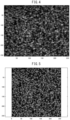
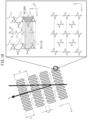
- TOF-SIMS measurement of the separator can be carried out with reference to FIG. 1 to FIG. 6 and FIG. 11 to FIG. 14
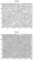
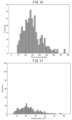
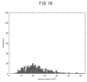
- Voronoi tessellation of TOF-SIMS image can be carried out with reference to FIG. 7 to FIG. 10 and FIG. 15 to FIG. 18 , respectively.
- the Si-containing molecules tend to be dispersed in a state of not being a sea-island structure in the separator.
- the nonaqueous secondary battery is a lithium ion secondary battery
- the separator containing Si elements dispersed uniformly therein coexist with a lithium (Li) complex solvated with an electrolytic solution having unshared electron pair such as oxygen atoms, it is considered that the product life in a battery cycle characteristic test is prolonged by the following phenomena (i) and (ii).
- lithium hexafluorophosphate exists as a constant concentration of dissociated F anions or lithium fluoride (LiF) in the system due to the Jahn-Teller effect possessed by phosphorus atoms. Therefore, in a state of being added to Si, LiF exhibits a stronger Lewis acid effect than that in a state before addition, which makes the above phenomena (i) and (ii) more remarkable, and thus satisfactory low-temperature cycle characteristics can also be exhibited.
- Such a concept is peculiar to the below-mentioned amorphous structure obtained by film formation of a polymer composition in which a resin A and a resin B or a resin C are used, and this approach differs from Lewis acidic properties of Si in the coordination complex of a low molecular weight allylsilane compound.
- the Si-containing molecules often have crosslinkability, for example, when they have silane crosslinkability, it is considered possible to ensure the silane crosslinkability of the Si-containing molecules dispersed even in a nonaqueous secondary battery and to ensure the stability of siloxane bonds, thereby making it possible to maintain the crosslinked structure of the separator for a long period of time, so that safety can be ensured in a safety test such as a nail penetration test. It has been known that when uneven flow of lithium ions moves at a lower rate than that of the intercalation reaction to electrodes during charging/discharging of a lithium ion battery, lithium ions accumulate in the electrical stagnation to form dendrites.
- the uniformity of lithium ion flow can be improved by designing a separator in which Si-containing atoms are dispersed in a state of not being a sea-island structure (not a matrix structure), and thus the problem has been solved, as described in NPL 1.
- the separator preferably contains, for example, a silane-modified polyethylene as Si-containing molecules, and it is more preferable that a silane crosslinking reaction proceeds when the separator comes in contact with an electrolytic solution.
- the Voronoi area (mu) at maximum frequency of Voronoi polygons obtained by carrying out Voronoi tessellation is preferably within a range of 1.5 ⁇ m 2 to 17.0 ⁇ m 2 , more preferably 4.0 ⁇ m 2 to 16.0 ⁇ m 2 , and still more preferably 6.0 ⁇ m 2 to 13.0 ⁇ m 2 .
- the spread ( ⁇ ) of the Voronoi area frequency distribution of the Si-containing image detected by the TOF-SIMS measurement is preferably within a range of 0.5 ⁇ m 2 to 8.5 ⁇ m 2 , more preferably 1.7 ⁇ m 2 to 6.3 ⁇ m 2 , and still more preferably 1.8 ⁇ m 2 to 4.2 ⁇ m 2 .
- the Voronoi tessellation is to carry out regional division by determining, with respect to a plurality of points (generatrices) arranged at arbitrary positions on a certain metric space, to which generatrix another point on the same space is the closest.
- the diagram including the thus obtained regions is called a Voronoi diagram.
- the boundary line of a plurality of regions defines part of a bisector between respective generatrices and each region forms a polygon (Voronoi polygon).
- the region that is not closed when carrying out Voronoi tessellation in the observation visual field is excluded from the calculation of the equation above.
- the region that is not closed includes, for example, a region obtained by applying Voronoi tessellation to a particle which is present in the boundary of the observation visual field and hidden from observation of a complete particle. Accordingly, in an image obtained by photographing at least a partial region of the separator surface, regarding a particle located at the edge of the image, it is preferable to confirm whether or not the particle is entirely observed.
- the ratio ( ⁇ /mu) of the spread ( ⁇ ) of the Voronoi area frequency distribution to the Voronoi area (mu) at maximum frequency preferably satisfies the following relationship. 0.06 ⁇ ⁇ / mu ⁇ 0 .70
- the ratio ( ⁇ /mu) in Voronoi tessellation can be regarded as an indicator that indicates whether or not the Si-containing molecules are uniformly dispersed on the separator surface.
- the ratio ( ⁇ /mu) is within a range of 0.06 to 0.70, the Si-containing molecules are uniformly dispersed on the separator surface and sufficiently contribute to the coexistence of the Li complex derived from the electrolytic solution and the separator and the silane crosslinking reaction of the separator in the nonaqueous secondary battery, and thus the cycle product life of the battery can be prolonged.
- the separator according to the second embodiment when TOF-SIMS measurement is carried out on a square area of 100 ⁇ m, at least one or more silicon-containing structures are detected, and preferably, it is detected that the Si-containing molecules are dispersed in a state of not being a sea-island structure in the separator.
- R represents, for example, methyl, ethyl, n-propyl, isopropyl, n-butyl, sec-butyl, isobutyl, tert-butyl, etc., or a siloxane bond crosslinked with neighboring silanol.
- the porosity of the separator is preferably 20% or more, more preferably 30% or more, and still more preferably 32% or more or 35% or more.
- the porosity of the microporous membrane is 20% or more, the puncture strength of the separator and the followability to rapid movement of lithium ions tends to be further improved.
- the porosity of the microporous membrane is preferably 90% or less, more preferably 80% or less, and still more preferably 50% or less.
- the porosity of the microporous membrane is 90% or less, the membrane strength is further improved and self-discharge tends to be further suppressed, and/or the air permeability is optimized.
- the porosity of the microporous membrane can be measured by the method mentioned in Examples.
- the membrane thickness of the separator is preferably 1.0 ⁇ m or more, more preferably 2.0 ⁇ m or more, and still more preferably 3.0 ⁇ m or more or 4.0 ⁇ m or more. When the membrane thickness of the separator is 1.0 ⁇ m or more, the membrane strength tends to be further improved.
- the membrane thickness of the separator is preferably 24 ⁇ m or less, more preferably 22 ⁇ m or less, and still more preferably 20 ⁇ m or less or 18 ⁇ m or less. When the membrane thickness of the separator is 24 ⁇ m or less, the ion permeability tends to be further improved.
- the membrane thickness of the separator can be measured by the method mentioned in Examples.
- the separator having a multilayer structure 2 includes a polyolefin microporous membrane as a substrate and a thermoplastic polymer-containing layer formed on at least one side of the polyolefin microporous membrane.
- the thermoplastic polymer contained in the thermoplastic polymer-containing layer includes polymerization units of (meth)acrylic acid ester and/or (meth)acrylic acid, or contains at least one fluorine atom-containing polyvinyl compound selected from the group consisting of polyvinylidene fluoride (PVDF), polyvinylidene fluoride-hexafluoropropylene (PVDF-HFP) and polyvinylidene fluoride-chlorotrifluoroethylene (PVDF-CTFE). Since the adhesive strength between the electrode and the separator is improved by including the thermoplastic polymer-containing layer, handling during battery production is improved.
- the crystallinity of the fluorine-based resin can be controlled within an appropriate range by copolymerizing HFP or CTFE with vinylidene fluoride, flow of the active layer can be suppressed during the adhesion treatment with the electrode. Further, in the case of the adhesion treatment with the electrode, since the adhesive force is improved, the interface deviation does not occur when used as the separator for a secondary battery, leading to an improvement in collapse test passing rate.
- meta-aromatic polyamide is preferable.
- meta-polyamide include polymetaphenylene isophthalamide and the like.
- para-polyamide include copolyparaphenylene/3.4'oxydiphenylene/terephthalamide and the like.
- the heat-resistant resin layer preferably contains 30% to 90% by weight of an inorganic material having an average particle size of 0.2 ⁇ m to 0.9 ⁇ m. By including the heat-resistant resin layer, thermal deformation of the separator is suppressed even if local short circuit occurs inside the battery, leading to an improvement in collapse test passing rate.
- the inorganic particles according to the multilayer structure 1 and/or the multilayer structure 3, and the inorganic filler according to the multilayer structure 4 may be an inorganic material mentioned later in the method for producing a separator for a nonaqueous secondary battery, and of which, preferred is at least one selected from the group consisting of alumina, silica, titania, zirconia, magnesia, ceria, yttria, zinc oxide, iron oxide, silicon nitride, titanium nitride, boron nitride, silicon carbide, aluminum hydroxide oxide, talc, kaolinite, dickite, nacrite, halloysite, pyrophyllite, montmorillonite, sericite, mica, amesite, bentonite, asbestos, zeolite, diatomaceous earth, quartz sand and glass fibers.
- alumina silica, titania, zirconia, magnesia, ceria, yttria
- the method for producing a microporous membrane according to the first to fifth embodiments includes the following steps:
- the crosslinked structure-forming step includes (1) a secondary step in which a plurality of functional groups included in the microporous membrane are subjected to a condensation reaction, (2) a secondary step in which the functional groups included in the microporous membrane are reacted with a chemical substance in the electricity storage device, or (3) a secondary step in which the functional groups included in the microporous membrane are reacted with other functional groups.
- the crosslinking promoting catalyst is an optional catalyst capable of promoting a crosslinking reaction, for example, (I) a condensation reaction of a plurality of the same functional groups described above, (II) a reaction between a plurality of different functional groups, (III) a chain condensation reaction between the functional groups and an electrolytic solution, and (IV) a chain condensation reaction between the functional groups and an additive.
- the crosslinking promoting catalyst may be, for example, an organometallic-containing catalyst or the like.
- a kneading machine can be used for kneading of a polyolefin, and optionally a plasticizer or inorganic material and other resins. From the viewpoint of suppressing the generation of resin aggregates during the production process and maintaining crosslinkability of the microporous membrane until housing in the battery, a master batch resin containing a crosslinking promoting catalyst is preferably not added to the kneaded mixture.
- the polyolefin used in the kneading step or the sheet-forming step (1) is not limited to an olefin homopolymer, and may be a polyolefin obtained by copolymerizing a monomer having a functional group, or a functional group-modified polyolefin.
- the functional group is a functional group that can be involved in the formation of a crosslinked structure, and may be, for example, the above-described alkoxysilyl group.
- the resin-modifying step can be eliminated by preparing a silane-modified polyethylene (resin A) as a starting material.
- the polyolefin starting material when the polyolefin starting material has no functional group capable of being involved in the formation of the crosslinked structure or the molar fraction of such a functional group is less than a predetermined ratio, the polyolefin starting material is subjected to the resin-modifying step, and the functional group is incorporated in the resin backbone or the molar fraction of the functional group is increased to obtain the functional group-modified polyolefin.
- the resin-modifying step may be carried out by a known method.
- the polyolefin starting material can be brought into contact with the reaction reagent by liquid spraying, gas spraying, dry mixing, immersion, coating or the like, so that the crosslinkable functional group can be introduced into the polyolefin backbone.
- the content of the resin A in the polyolefin starting material subjected to the sheet-forming step (1) is preferably 3 to 70% by weight, more preferably 5 to 60% by weight, and still more preferably 10 to 50% by weight, based on the total weight of the solid content of the polyolefin starting material.
- the content of the resin B in the polyolefin starting material is preferably 3 to 70% by weight, more preferably 5 to 60% by weight, and still more preferably 5 to 40% by weight, based on the total weight of the solid content of the polyolefin starting material.
- the content of the resin C in the polyolefin starting material is preferably 1 to 90% by weight, more preferably 5 to 60% by weight, and still more preferably 5 to 50% by weight, based on the total weight of the solid content of the polyolefin starting material.
- the weight ratio (A/B) of the resin A to the resin B to be subjected to the sheet-forming step (1) is preferably 0.07 to 12.00, more preferably 0.10 to 11.00, and still more preferably 0.50 to 10.00.
- the weight ratio (A/C) of the resin A to the resin C to be subjected to the sheet-forming step (1) is preferably 0.07 to 12.00, more preferably 0.10 to 11.00, and still more preferably 0.20 to 10.00.
- the weight ratio (B/C) of the resin B to the resin C to be subjected to the sheet-forming step (1) is preferably 0.06 to 7.00, more preferably 0.10 to 7.00, and still more preferably 0.12 to 6.90.
- the molecular weight Mn, Mw and Mv, or Mw/Mn of the resins A to C to be subjected to the sheet-forming step (1) are preferably the same as those described above for the separator constituent elements.
- the characteristics related to Voronoi tessellation of the separators according to the first to fifth embodiment are easily achieved.
- the resin A is preferably not a master batch resin containing a catalyst that promotes the crosslinking reaction of the alkoxysilyl group from before the sheet-forming step.
- plasticizer used in the sheet-forming step (1) examples include, but are not particularly limited to, organic compounds that can form homogeneous solutions with polyolefins at a temperature below the boiling point thereof. More specifically, these include decalin, xylene, dioctyl phthalate, dibutyl phthalate, stearyl alcohol, oleyl alcohol, decyl alcohol, nonyl alcohol, diphenyl ether, n-decane, n-dodecane, paraffin oil and the like. Of these, paraffin oil and dioctyl phthalate are preferable.
- the plasticizer may be used alone, or two or more thereof may be used in combination.
- each proportion of the plasticizer is not particularly limited, and from the viewpoint of the porosity of the obtained microporous membrane, each proportion of the polyolefin and the silane-modified polyolefin is preferably 20% by weight or more, and from the viewpoint of the viscosity during melt kneading, each proportion is preferably 90% by weight or less.
- the sheet-forming step (1) is a step in which the obtained kneaded mixture or a mixture of the polyolefin and the plasticizer is extruded, cooled to solidify, and cast into a sheet form to obtain a sheet.
- the sheet forming method is not particularly limited, and may be a method of compressed-cooling or deformation-cooling solidification of a molten mixture obtained by melt kneading and extrusion.
- the cooling method may be a method of direct contact with a cooling medium such as cold air or cooling water; or a method of contact with a refrigerant-cooled roll or a pressing machine, with a method of contact with a refrigerant-cooled roll or a pressing machine being preferable for superior membrane thickness control.
- the stretching step (2) is a step in which the plasticizer or inorganic filler is extracted from the obtained sheet as necessary, and the sheet is further stretched in at least one direction.
- Examples of the method of stretching the sheet include MD uniaxial stretching with a roll stretcher, TD uniaxial stretching with a tenter, sequential biaxial stretching with a combination of a roll stretcher and tenter, or a tenter and tenter, simultaneous biaxial stretching with a biaxial tenter or inflation molding and the like. Simultaneous biaxial stretching is preferable from the viewpoint of obtaining a more homogeneous membrane.
- the total area increase is preferably 8-fold or more, more preferably 15-fold or more, and still more preferably 20-fold or more or 30-fold or more, from the viewpoint of membrane thickness homogeneity, and balance between tensile elongation, porosity and mean pore size. If the total area increase is 8-fold or more, it will tend to be easier to obtain high strength and a satisfactory thickness distribution. The area increase is also 250-fold or less from the viewpoint of preventing rupture.
- the porous body-forming step (3) is a step in which the plasticizer and/or the inorganic filler is/are extracted from the stretched sheet after the stretching step to form pores, thus obtaining a microporous membrane.
- the method of extracting the plasticizer include, but are not particularly limited to, a method of immersing the stretched sheet in an extraction solvent or a method of showering the stretched sheet with an extraction solvent, for example.
- the extraction solvent used is not particularly limited, but it is preferably a solvent which is a poor solvent for the polyolefin and a satisfactory solvent for the plasticizer and/or inorganic filler, and a solvent having a boiling point which is lower than the melting point of the polyolefin.
- extraction solvents examples include hydrocarbons such as n-hexane and cyclohexane; halogenated hydrocarbons such as methylene chloride, 1,1,1-trichloroethane and fluorocarbon-based compounds; alcohols such as ethanol and isopropanol; ketones such as acetone and 2-butanone; and alkali water.
- the extraction solvent may be used alone, or two or more thereof may be used in combination.
- the heat treatment step (4) is a step in which, after the stretching step, the plasticizer is further extracted from the sheet as necessary before the heat treatment.
- the method of heat treatment include, but are not particularly limited, to a heat setting method in which a tenter and/or roll stretcher is utilized for stretching and relaxation procedures.
- a relaxation procedure is a procedure of shrinking carried out at a prescribed temperature and relaxation factor, in the machine direction (MD) and/or transverse direction (TD) of the membrane.
- the relaxation factor is the value of the MD dimension of the membrane after the relaxation procedure divided by the MD dimension of the membrane before the procedure, or the value of the TD dimension after the relaxation procedure divided by the TD dimension of the membrane before the procedure, or the product of the relaxation factor in the MD and the relaxation factor in the TD, when both the MD and TD have been relaxed.
- the stretching and relaxation procedures in the heat treatment step (4) is preferably carried out at least in the TD direction.
- a coating solution is applied on at least one surface of the polyolefin microporous membrane obtained as mentioned above, or at least one surface of the heat-treated porous body obtained in the heat treatment step (4).
- a known coating method can be employed, and examples thereof include a method of applying a coating solution on a substrate, a microporous membrane or a heat-treated porous body, a method of stacking and extruding a starting material of a microporous membrane and a starting material of another layer by a co-extrusion method, a method of separately fabricating both layers and bonding them and the like.
- the coating step (5) may be any one or optional combination of the following steps (SA) to (5D):
- the coating step (5A) it is possible to form a multilayer membrane including a polyolefin microporous membrane and an inorganic porous layer according to the preferred multilayer structure 1 described above.
- the coating step (5B) it is possible to form a multilayer membrane including a polyolefin microporous membrane and a thermoplastic polymer-containing layer according to the preferred multilayer structure 2 described above.
- the coating step (5C) it is possible to form a multilayer membrane including a polyolefin microporous membrane and an active layer according to the preferred multilayer structure 3 described above.
- the coating step (5D) it is possible to form a multilayer membrane including a polyolefin microporous membrane and a heat-resistant resin layer according to the preferred multilayer structure 4 described above.
- the organic solvent contained in the nonaqueous coating solution enters into the amorphous portions of the polyolefin microporous single-layer membrane or the heat-treated porous body, thereby enabling promotion of the silane crosslinking reaction of the silane-modified polyolefin.
- the coating solution for forming a thermoplastic polymer-containing layer is allowed to contain a thermoplastic polymer, and the thermoplastic polymer contains at least one selected from the group consisting of polymerization units of (meth) acrylic acid ester and/or (meth) acrylic acid, polyvinylidene fluoride (PVDF), polyvinylidene fluoride-hexafluoropropylene (PVDF-HFP) and polyvinylidene fluoride-chlorotrifluoroethylene (PVDF-CTFE).
- PVDF polyvinylidene fluoride
- PVDF-HFP polyvinylidene fluoride-hexafluoropropylene
- PVDF-CTFE polyvinylidene fluoride-chlorotrifluoroethylene
- the coating solution for forming an active layer is allowed to contain a fluorine atom-containing polyvinyl compound, and the fluorine atom-containing polyvinyl compound is at least one elected from the group consisting of polyvinylidene fluoride-hexafluoropropylene (PVDF-HFP) and polyvinylidene fluoride-chlorotrifluoroethylene (PVDF-CTFE).
- PVDF-HFP polyvinylidene fluoride-hexafluoropropylene
- PVDF-CTFE polyvinylidene fluoride-chlorotrifluoroethylene
- the coating solution may optionally contain resin binders, inorganic particles or inorganic fillers, dispersants, surfactants, solvents and the like.
- the coating solution for forming an inorganic porous layer is lowed to contain inorganic particles and a resin binder.
- resin binders examples include the followings:
- the resin binder preferably contains polymerization units of (meth)acrylic acid ester and/or (meth)acrylic acid, from the viewpoint of improving the safety in a puncture test of the battery including the separator.
- the resin binder described above can be produced by a known polymerization method using a corresponding monomer or comonomer. It is possible to employ, as the polymerization method, for example, appropriate method such as solution polymerization, emulsion polymerization or bulk polymerization.
- a particulate binder polymer is formed by emulsion polymerization, and the obtained polymer emulsion is used as an aqueous latex.
- the coating solution for forming an inorganic porous layer, an active layer or a heat-resistant resin layer is allowed to contain inorganic particles or an inorganic filler.
- inorganic particles or inorganic fillers include, but are not limited to, oxide-based ceramics such as alumina, silica, titania, zirconia, magnesia, ceria, yttria, zinc oxide and iron oxide; nitride-based ceramics such as silicon nitride, titanium nitride and boron nitride; ceramics such as silicon carbide, calcium carbonate, magnesium sulfate, aluminum sulfate, aluminum hydroxide, aluminum hydroxide oxide, potassium titanate, talc, kaolinite, dickite, nacrite, halloysite, pyrophyllite, montmorillonite, sericite, mica, amesite, bentonite, asbestos, zeolite, calcium silicate, magnesium silicate, diatomaceous earth and quartz
- ⁇ -alumina ⁇ -alumina, ⁇ -alumina, ⁇ -alumina and ⁇ -alumina, and all of them can be preferably used.
- ⁇ -alumina is preferable, since it is thermally and chemically stable.
- the aluminum oxide compound is particularly preferably aluminum hydroxide (AlO(OH)).
- the aluminum hydroxide is more preferably boehmite from the viewpoint of preventing internal short circuit caused by the generation of lithium dendrite.
- particles mainly composed of boehmite as the inorganic filler constituting the active layer, it is possible to realize a very light-weight porous layer while maintaining high permeability, and to suppress heat shrinkage at high temperature of the porous membrane even in a thinner porous layer, and to exhibit excellent heat resistance.
- Synthetic boehmite which can reduce ionic impurities that adversely affect the properties of the electrochemical device, is still more preferable.
- the content of the inorganic particles contained in the coating solution for forming the inorganic porous layer is preferably 5% by weight to 99% by weight, and more preferably 10% by weight or more and less than 99% by weight, based on the weight of the total solid content of the coating solution.
- the inorganic filler contained in the coating solution for forming a heat-resistant resin layer preferably has an average particle size of 0.2 ⁇ m to 0.9 ⁇ m, and/or the content of the inorganic filler in the coating solution is preferably 30% by weight to 90% by weight, based on the weight of the total solid content of the coating solution.
- Examples of the dispersant contained in the coating solution include an aqueous ammonium polycarboxylate solution.
- examples of the surfactant contained in the coating solution include emulsifiers, soaps and the like.
- Examples of the solvent contained in the coating solution include water (for example, ion-exchanged water, pure water, etc.), aqueous solvents (for example, a mixture of water and alcohol, etc.), organic solvents, and the like.
- Examples of the organic solvent include alcohol, N-methylpyrrolidone (NMP), N,N-dimethylformamide (DMF), N,N-dimethylacetamide (DMA), ethanol, toluene, hot xylene, methylene chloride, hexane and the like.
- Examples of the method for preparing a coating solution containing inorganic particles or inorganic filler include a mechanical stirring method using a ball mill, a bead mill, a planetary ball mill, a vibrating ball mill, a sand mill, a colloid mill, an attritor, a roll mill, a high-speed impeller dispersion, a disperser, a homogenizers, a high-speed impact mill, an ultrasonic dispersion, a stirring blade and the like.
- Examples of the method for applying a coating solution containing inorganic particles or inorganic filler include a gravure coater method, a small diameter gravure coater method, a reverse roll coater method, a transfer roll coater method, a kiss coater method, a dip coater method, a knife coater method, an air doctor coater method, a blade coater method, a rod coater method, a squeeze coater method, a cast coater method, a die coater method, a screen printing method, a spray coating method and the like.
- a step of introducing the coating film into an atmosphere with a humidity of 50% or higher or blowing steam over the coating surface may be included. Precipitation of an aramid resin can be promoted by maintaining humidity of the coated surface.
- the solvent is removed from the coating film formed in the coating step (5).
- the method for removing the solvent include a method of drying at a temperature below the melting point of a material constituting a microporous membrane, a method of drying under reduced pressure at low temperature, a method of drying after substituting the solvent contained in the coating solution with another solvent and the like. A part of the solvent may remain as long as it does not significantly affect the characteristics of the nonaqueous secondary battery.
- the method of substituting the solvent contained in the coating solution with another solvent include a method of immersing the membrane in another solvent described above, a method of spraying another solvent described above over the membrane and the like.
- the solvent in the coating film formed in the coating step (5) may be substituted with another solvent.
- the solvent before substitution include solvents such as DMF, DMA, NMP and DMSO
- examples of the solvent after substitution include solvents such as water and alcohol.
- the method for producing a separator may include a winding/slitting step as necessary.
- the winding/slitting step is a step in which the obtained microporous membrane is slit as necessary and wound on a prescribed core.
- step (7) electrodes and a laminated body or wound body of the separator are housed in the exterior body.
- the step (7) can be carried out in the same manner as in the production of a nonaqueous secondary battery mentioned later, and the electrodes, nonaqueous electrolytic solution and exterior body used in step (7) may be those described for the nonaqueous secondary battery.
- the silane-modified polyolefin contained in the separator forms a crosslinked structure.
- the separator obtained by the method including various steps described above can be used for a nonaqueous secondary battery including positive and negative electrodes capable of occluding and releasing lithium, and a nonaqueous electrolytic solution prepared by dissolving an electrolyte in a nonaqueous solvent, and is preferably used for a lithium secondary battery or a lithium ion secondary battery.
- the nonaqueous secondary battery is configured by housing a positive electrode, a negative electrode, a separator and a nonaqueous electrolytic solution in an optional battery exterior body.
- the positive electrode is connected to a positive electrode lead body in the nonaqueous secondary battery and the negative electrode is connected to a negative electrode lead body in the nonaqueous secondary battery, and one end side is drawn out to the outside of the battery exterior body so that the positive electrode lead body and the negative electrode lead body are respectively connected to an external device, and the ionomer portions thereof are heat-fused together with one side of the battery exterior body.
- the positive electrode is composed of a positive electrode current collector and a positive electrode active material layer.
- the negative electrode is composed of a negative electrode current collector and a negative electrode active material layer.
- the positive electrode active material layer contains a positive electrode active material, and the negative electrode active material layer contains a negative electrode active material.
- the positive electrode and the negative electrode are disposed such that a positive electrode active material layer and a negative electrode active material layer face each other with a separator interposed therebetween.
- a known positive electrode for a battery can be used, and from the viewpoint of operational advantage of the present invention, a positive electrode which easily cause thermal decomposition or O 2 can also be used.
- a composite positive electrode active material of lithium and other metals can also be used, and it is possible to use a composite positive electrode of at least one metal selected from the group consisting of nickel, manganese and cobalt, and lithium, for example, an LNO positive electrode, an NCA positive electrode, an LCO positive electrode, a positive electrode containing a lithium (Li)-nickel (Ni)-manganese (Mn)-cobalt (Co) composite oxide as a positive electrode active material (NMC positive electrode) and the like.
- the NMC positive electrode is preferable, and of the NMC positive electrodes, those having a relatively high nickel content are more preferably used.
- the molar ratio of the amount of nickel (Ni) relative to the total amount of nickel, manganese and cobalt of the positive electrode is more preferably 3 to 9, 5 to 9, 6 to 9, 5 to 8 or 6 to 8, and particularly preferably 5 to 9.
- the positive electrode current collector can be composed of, for example, metal foils such as aluminum foil, nickel foil and stainless steel foil.
- negative electrode active material constituting the negative electrode examples include, in addition to carbon materials typified by hard carbon, graphite, pyrolytic carbon, coke, vitreous carbon, calcined body of organic polymer compound, microbead, carbon fiber, activated carbon, carbon colloid and carbon black, metal lithium, metal oxide, metal nitride, lithium alloy, tin alloy, silicon (Si)-containing material, intermetallic compound, organic compound, inorganic compound, metal complex, organic polymer compound and the like.
- the negative electrode active material is used alone, or in combination of two or more thereof.
- the Si-containing material is preferable as the negative electrode active material, and examples thereof include silicon, Si alloys, and Si oxides. From the same point of view, the proportion of Si in the negative electrode active material is preferably 5 to 90 mol%.
- the Si-containing negative electrode active material the storage capacity of lithium ions is significantly improved compared to the carbon material negative electrode and, at the same time, lithium ions are charged and discharged to the Si-containing particles and, as disclosed in NPL2, the Si-containing negative electrode active material undergoes significant volume expansion and contraction. In that case, the volume inside the battery is constant and the separator is significantly compressed or deformed in the thickness direction by the Si-containing negative electrode active material.
- the separator can maintain permeability even if compressed or deformed in the thickness direction in the nonaqueous secondary battery, and is excellent in balance between strength and ion diffusivity, and is capable of improving the collapse test passing rate, cycle test capacity retention rate and high-temperature cycle life of the nonaqueous secondary battery, and/or balancing them.
- the separator having a structure in which Si atoms are dispersed in a state of not being a sea-island structure which has been found according to the present invention, uniform progress of the intercalation reaction to the Si-containing negative electrode active material as mentioned above, leading to uniform expansion and contraction of the Si-containing negative electrode active material inside the battery, thus enabling suppression of deviation of the winding structure inside the battery and improvement in battery cycle characteristics and safety of the battery.
- the negative electrode current collector can be composed of, for example, metal foils such as copper foil, nickel foil and stainless steel foil.
- the nonaqueous electrolytic solution refers to an electrolytic solution containing an electrolyte in a nonaqueous solvent in which the amount of water is 1% by weight or less based on the total weight.
- the nonaqueous electrolyte preferably does not contain water as much as possible, but may contain a very small amount of moisture.
- the content of such moisture is preferably 300 ppm by weight or less, and more preferably 200 ppm by weight or less, based on the total amount of the nonaqueous electrolytic solution.
- the electrolytic solution in the battery may contain moisture, and the moisture contained in the system after the fabrication of the battery may be moisture contained in the electrolytic solution or brought-in moisture contained in a member such as an electrode or a separator.
- the electrolytic solution may contain a nonaqueous solvent.
- the solvent contained in the nonaqueous solvent include alcohols such as methanol and ethanol; and aprotic solvents. Of these, an aprotic solvent is preferable as the nonaqueous solvent.
- aprotic solvent examples include cyclic carbonate, fluoroethylene carbonate, lactone, organic compound having a sulfur atom, chain fluorinated carbonate, cyclic ether, mononitrile, alkoxy group-substituted nitrile, dinitrile, cyclic nitrile, short-chain fatty acid ester, chain ether, fluorinated ether, ketone, and compounds in which a part or all of H atoms in the aprotic solvent is substituted with a halogen atom.
- cyclic carbonate examples include ethylene carbonate, propylene carbonate, 1,2-butylene carbonate, trans-2,3-butylene carbonate, cis-2,3-butylene carbonate, 1,2-pentylene carbonate, trans-2,3-pentylene carbonate, cis-2,3-pentylene carbonate, vinylene carbonate, 4,5-dimethylvinylene carbonate and vinyl ethylene carbonate.
- fluoroethylene carbonate examples include 4-fluoro-1,3-dioxolan-2-one, 4,4-difluoro-1,3-dioxolan-2-one, cis-4,5-difluoro-1,3-dioxolan-2-one, trans-4,5-difluoro-1,3-dioxolan-2-one, 4,4,5-trifluoro-1,3-dioxolan-2-one, 4,4,5,5-tetrafluoro-1,3-dioxolan-2-one and 4,4,5-trifluoro-5-methyl-1,3-dioxolan-2-one.
- lactone examples include ⁇ -butyrolactone, ⁇ -methyl- ⁇ -butyrolactone, ⁇ -valerolactone, ⁇ -caprolactone, ⁇ -valerolactone, ⁇ -caprolactone and ⁇ -caprolactone.
- Examples of the organic compound having a sulfur atom include ethylene sulfite, propylene sulfite, butylene sulfite, pentene sulfite, sulfolane, 3-sulfylene, 3-methylsulfolane, 1,3-propanesultone, 1,4-butanesultone, 1-propene 1,3-sultone, dimethyl sulfoxide, tetramethylene sulfoxide and ethylene glycol sulfite.
- chain carbonate examples include ethyl methyl carbonate, dimethyl carbonate, diethyl carbonate, methyl propyl carbonate, methyl isopropyl carbonate, dipropyl carbonate, methyl butyl carbonate, dibutyl carbonate, ethyl propyl carbonate and the like.
- cyclic ether examples include tetrahydrofuran, 2-methyltetrahydrofuran, 1,4-dioxane and 1,3-dioxane.
- Examples of the mononitrile include acetonitrile, propionitrile, butyronitrile, valeronitrile, benzonitrile and acrylonitrile.
- alkoxy group-substituted nitrile examples include methoxyacetonitrile and 3-methoxypropionitrile.
- Examples of the dinitrile include malononitrile, succinonitrile, methylsuccinonitrile, glutaronitrile, 2-methylglutaronitrile, adiponitrile, 1,4-dicyanoheptane, 1,5-dicyanopentane, 1,6-dicyanohexane, 1,7-dicyanoheptane, 2,6-dicyanoheptane, 1,8-dicyanooctane, 2,7-dicyanooctane, 1,9-dicyanononane, 2,8-dicyanononane, 1,10-dicyanodecane, 1,6-dicyanodecane, 2,4-dimethylglutaronitrile, ethylene glycol bis(propionitrile)ether and the like.
- cyclic nitrile examples include benzonitrile and the like.
- Examples of the short-chain fatty acid ester include methyl acetate, methyl propionate, methyl isobutyrate, methyl butyrate, methyl isovalerate, methyl valerate, methyl pivalate, methyl hydroangelate, methyl caproate, ethyl acetate, ethyl propionate, ethyl isobutyrate, ethyl butyrate, ethyl isovalerate, ethyl valerate, ethyl pivalate, ethyl hydroangelate, ethyl caproate, propyl acetate, propyl propionate, propyl isobutyrate, propyl butyrate, propyl isovalerate, propyl valerate, propyl pivalate, propyl hydroangelate, propyl caproate, isopropyl acetate, isopropyl propionate, isopropyl butyrate, isopropyl isobut
- chain ether examples include dimethoxyethane, diethyl ether, 1,3-dioxolane, diglyme, triglyme and tetraglyme.
- fluorinated ether examples include compounds represented by the general formula Rf a a -OR b b (wherein Rf a a is an alkyl group having a fluorine atom and R b b is an organic group which optionally has a fluorine atom).
- ketone examples include acetone, methyl ethyl ketone and methyl isobutyl ketone.
- Examples of the compound in which a part or all of the H atoms in the aprotic solvent are substituted with a halogen atom include a compound in which a halogen atom is fluorine.
- fluoride of the chain carbonate examples include methyl trifluoroethyl carbonate, trifluorodimethyl carbonate, trifluorodiethyl carbonate, trifluoroethyl methyl carbonate, methyl 2,2-difluoroethyl carbonate, methyl 2,2,2-trifluoroethyl carbonate and methyl 2,2,2,3-tetrafluoropropyl carbonate.
- the fluorinated chain carbonate can be represented by the following general formula: R c c -O-C(O)O-R d d wherein R cc and R d d are at least one selected from the group consisting of CH 3 , CH 2 CH 3 , CH 2 CH 2 CH 3 , CH(CH 3 ) 2 , and formula CH 2 Rf ee (wherein Rf ee is an alkyl group having 1 to 3 carbon atoms in which hydrogen atoms are substituted with at least one fluorine atom), and R cc and/or R d d has/have at least one fluorine atom.
- fluoride of the short-chain fatty acid ester examples include fluorinated short-chain fatty acid esters typified by, for example, 2,2-difluoroethyl acetate, 2,2,2-trifluoroethyl acetate and 2,2,3,3-tetrafluoropropyl acetate.
- the fluorinated short chain fatty acid ester is represented by the following general formula: R f f -O-C(O)O-R g g wherein R f f is at least one selected from the group consisting of CH 3 , CH 2 CH 3 , CH 2 CH 2 CH 3 , CH(CH 3 ) 2 , CF 3 CF 2 H, CFH 2 , CF 2 H, CF 2 Rf h h , CFHRf h h and CH 2 Rf i i , R g g is at least one selected from the group consisting of CH 3 , CH 2 CH 3 , CH 2 CH 2 CH 3 , CH(CH 3 ) 2 and CH 2 Rf i i , Rf h h is an alkyl group having 1 to 3 carbon atoms in which a hydrogen atom is substituted with at least one fluorine atom, Rf i i is an alkyl group having 1 to 3 carbon atoms in which a hydrogen atom is
- the nonaqueous electrolytic solution preferably contains ethyl methyl carbonate (EMC) and/or acetonitrile (AcN) as a nonaqueous solvent, and/or the total content of EMC and AcN in the nonaqueous electrolytic solution is preferably within a range of 50% by weight to 90% by weight.
- EMC ethyl methyl carbonate
- AcN acetonitrile
- the electrolyte is preferably a lithium salt, and more preferably a fluorine-containing lithium salt that generates hydrogen fluoride (HF) from the viewpoint of promoting the silane crosslinking reaction.
- fluorine-containing lithium salt include lithium hexafluorophosphate (LiPF 6 ), lithium fluorosulfonate (LiFSO 3 ), lithium bis(trifluoromethanesulfonyl)imide (LiN(SO 2 CF 3 ) 2 ), lithium bis(fluorosulfonyl)imide (LiN(SO 2 F) 2 ), lithium borofluoride (LiBF 4 ) and lithium bis(oxalate)borate (LiBC 4 O 8 ).
- the LiPF 6 reacts with a slight amount of moisture (moisture contained in a member such as an electrode, a separator, an electrolytic solution or the like) to produce HF, or a fluorine-containing organic substance derived from HF. It is considered that HF or the fluorine-containing organic substance derived from HF is dissolved in the electrolytic solution, and swollen and diffused to the amorphous portions in the polyolefin having a crosslinkable silane group, thus catalyzing the silane crosslinking reaction.
- moisture moisture contained in a member such as an electrode, a separator, an electrolytic solution or the like
- the concentration of a lithium salt in the nonaqueous electrolytic solution is preferably relatively higher, more preferably within a range of 1.2 mol/L to 10 mol/L, still more preferably 1.5 mol/L or more, and particularly preferably 3.0 mol/L or more.
- lithium hexafluorophosphate exists as a constant concentration of dissociated F anions or lithium fluoride (LiF) in the system due to the Jahn-Teller effect possessed by phosphorus atoms.
- LiF battery life reduction phenomenon such as electrode corrosion due to dissociated F anions
- LiF exhibits a stronger Lewis acid effect than that in a state before addition, which makes the above phenomena (i) and (ii) more remarkable, and thus satisfactory low-temperature cycle characteristics can also be exhibited.
- the nonaqueous electrolytic solution may include, as the substance that exerts a catalytic action on the silane crosslinking reaction, in addition to the above, for example, substances that react with a nonaqueous electrolytic solution and/or moisture contained in a trace amount in the nonaqueous electrolytic solution to generate hydrogen ions, such as inorganic acids or organic acids (acid sources), substances that react with a nonaqueous electrolytic solution and/or moisture contained in a trace amount in the nonaqueous electrolytic solution to generate hydroxide ions (alkaline sources).
- the alkali source include alkali metal hydroxides, alkaline earth metal hydroxides, alkali metal carbonates, alkali metal phosphates, ammonia, amine compounds, and the like.
- alkali metal hydroxides or alkaline earth metal hydroxides are preferable, alkali metal hydroxides are more preferable, and sodium hydroxide is still more preferable.
- the configuration of the battery exterior body of the nonaqueous secondary battery a known configuration.
- a battery can or a laminated film exterior body may be used as the battery exterior body.
- the shape of the nonaqueous secondary battery can be applied to, for example, a square-type, a square cylinder-type, a cylindrical-type, an elliptical-type, a button-type, a coin type, a flat-type, a laminated-type and the like.
- the nonaqueous secondary battery can be fabricated in the same manner as in a known production method, except for using the above-mentioned nonaqueous electrolytic solution, positive electrode, negative electrode, separator and battery exterior body.
- the present invention will be described in more detail by way of Examples. However, the present invention is not limited to these Examples. Physical properties in the Examples were measured by the following methods. Regarding the substrate weight per unit area, the substrate thickness, the substrate porosity, the substrate air permeability, the substrate puncture strength, SAXS, WAXS, NMR and TOF-SIMS, if there was a coating layer on the substrate, the measurement was carried out after the coating layer was scraped off. Regarding the collapse test passing rate, the cycle test capacity retention rate and the cycle life test, the measurement was carried out without scraping off the coating layer even if there is a coating layer on the substrate. All of the battery evaluation tests (collapse test, cycle capacity retention rate, high-temperature cycle life) were carried out 4 days after coating the separator with the coating solution.
- the silane-modified polyolefin contained in the separator When the silane-modified polyolefin contained in the separator is in a crosslinked state, it is insoluble or has insufficient solubility in an organic solvent, and it is therefore difficult to directly measure the content of the silane-modified polyolefin from the separator.
- the siloxane bonds are decomposed into methoxysilanol using methyl orthoformate which does not undergo a secondary reaction, and then solution NMR measurement is carried out, thus enabling detection of the silane-modified polyolefin contained in the separator and preforming GPC measurement thereof.
- the pretreatment test can be carried out with reference to JP 3529854 B2 and JP 3529858 B2 . After the opening polymerization reaction, thermal analysis such as TMA and DMA can be performed.
- 1 H or 13 C NMR identification of the silane-modified polyolefin as a starting material to be used for the production of a separator may be utilized in the method for detecting a silane-modified polyolefin contained in the separator.
- the sample is dissolved in o-dichlorobenzene-d4 at 140°C to obtain a 1 H-NMR spectrum at a proton resonance frequency of 600 MHz.
- the 1 H NMR measuring conditions are as follows.
- the sample is dissolved in o-dichlorobenzene-d4 at 140°C and a 13 C-NMR spectrum is obtained.
- the 13 C-NMR measuring conditions are as follows.
- the 1 H and/or 1 3 C-NMR measurement(s) allow(s) the amount of silane unit modification and the amount of polyolefin alkyl group modification, the C4 unit modification rate (mol%) and the number of methylene (CH 2 )s of silane graft linking portions in the silane-modified polyolefin to be confirmed for a polyolefin starting material, and allow(s) the silane-modified polyolefin contained in the separator to be determined.
- the amount of the silanol unit modification in the resin A can be quantified by NMR chemical shift of methylene next to the Si atom and the integrated value (-CH 2 -Si: 1 H, 0.69 ppm, t; 1 3 C, 6.11 ppm, s).
- Propylene modification (C3) can be quantified by NMR chemical shift and the integrated value of a terminal methyl group (-CH 3 : 1 3 C, 19.42 ppm, s).
- Butene modification (C4) can be quantified by NMR chemical shift and the integrated value of a terminal methyl group (-CH 3 : 1 3 C, 10.63 ppm, s).
- Standard polystyrene was measured using Model ALC/GPC 150C (trademark) by Waters Co. under the following conditions, and a calibration curve was drawn. The chromatogram for each polymer was also measured under the same conditions, and the weight-average molecular weight of each polymer was calculated by the following method, based on the calibration curve.
- the same Q factor as for polyethylene was used for silane-modified polyethylene, and the same Q factor as for polypropylene was used for silane-modified polypropylene.
- the weight-average molecular weight was calculated in the same manner as for polyethylene, except that the Q factor value for the polyolefin with the largest mass fraction was used.
- the limiting viscosity [ ⁇ ] at 135°C in a decalin solvent was determined based on ASTM-D4020.
- Mv of polyethylene and silane-modified polyethylene was calculated by the following formula.
- ⁇ 6.77 ⁇ 10 ⁇ 4 Mv 0.67
- Mv of polypropylene was calculated by the following formula.
- ⁇ 1.10 ⁇ 10 ⁇ 4 Mv 0.80
- melt mass-flow rate measuring device manufactured by Toyo Seiki Seisaku-sho, Ltd. (Melt Indexer F-F01)
- MFR value the weight of the resin extruded for 10 minutes under conditions of 190°C and 2.16 kg pressure for polyethylene and silane-modified polyethylene was determined as the MFR value.
- MFR measurement was carried out at 230°C.
- the thickness of the microporous membrane was measured at room temperature of 23 ⁇ 2°C and relative humidity of 60% using a micro thickness meter KBM (trademark) manufactured by Toyo Seiki Seisaku-Sho, Ltd. Specifically, the membrane thickness was measured at five points at approximately equal intervals over the full width in the TD direction to obtain an average value thereof.
- the coating film thickness is calculated by cross-sectional or lateral observation at an arbitrary magnification using SEM.
- a 10 cm ⁇ 10 cm square sample was cut out from a microporous membrane, and the volume (cm 3 ) and mass (g) of the sample were determined and used together with the density (g/cm 3 ) by the following formula to obtain a porosity.
- the air permeability of the sample was measured by an Oken-type air-permeability&smoothness tester EGO1-55-1MR (trademark) manufactured by Asahi Seiko Co., Ltd.
- the puncture strength of a microporous membrane was determined by carrying out a puncture test under the conditions of a radius of curvature of the tip of the needle of 0.5 mm and a punching speed of 2 mm/sec.
- SAXS small-angle X-ray scattering
- SAXS small-angle X-ray scattering
- a slurry was prepared by mixing the sample and propylene glycol at a weight ratio of 1:1 in order to reduce scattering derived from the particle size, and then the measurement was carried out.
- the crystal long period was analyzed by the following method. Empty cell scattering correction was carried out on the X-ray scattering pattern obtained from the imaging plate, and one-dimensional SAXS profile I(q) was obtained by circular averaging. Note that q is the absolute value of the scattering vector.
- the SAXS profile was multiplied by the square of the absolute value of the scattering vector to emphasize the scattering derived from the crystal long period. Subsequently, the SAXS profile multiplied by the square of the absolute value of the scattering vector and the logarithm of each absolute value of the scattering vector with base 10 were plotted on the vertical and horizontal axes. The horizontal axis represents log 1 0 q, and the vertical axis represents log 1 0 (I(q) ⁇ q2).
- the wide-angle X-ray scattering (WAXS) of the polyolefin microporous membrane as the separator substrate by the reflection method was measured under the following conditions.
- a wide-angle X-ray scattering measurement was carried out by the reflection method.
- the sample was irradiated with CuK ⁇ rays and scattering was detected by an imaging plate.
- the wide-angle X-ray scattering measurement was carried out under the conditions of a sample-detector distance of 95.2 mm and an output of 60 kV and 45 mA.
- the sample was set so that the cross-section of the sample and the incident direction of X-rays formed an angle of 10.5°. If the microporous membrane has a small thickness, the measurement cannot be carried out accurately, so that the membrane is stacked as necessary to obtain a sufficient strength.
- detector background correction and empty cell scattering correction were carried out on the X-ray scattering pattern obtained from the imaging plate.
- I ⁇ A + B ⁇ exp ⁇ ⁇ ⁇ ⁇ 0 / w 2
- WAXS Wide-angle X-ray scattering
- the sample was set so that the cross-section of the sample and the incident direction of X-rays formed an angle of 10.5°. If the microporous membrane has a small thickness, the measurement cannot be carried out accurately, so that the membrane is stacked as necessary to obtain sufficient strength.
- the (110) and (200) plane diffraction peaks were approximated by the Voigt function and the amorphous peaks were approximated by the Gauss function.
- the amorphous portion thickness (nm) and the crystal portion thickness (nm) were calculated according to the following formula.
- Amorphous portion thickness [nm] (crystal long period [nm]) ⁇ (1 - crystallinity degree [%]/100)
- the separators obtained in Examples and Comparative Examples were subjected to TOF-SIMS analysis.
- a nano-TOF manufactured by ULVAC-PHI, INCORPORATED was used as a TOF-SIMS mass spectrometer.
- the analysis conditions are as follows.
- Spectral detection of Si ions was carried out under the above conditions.
- the TOF-SIMS analysis results of the separator of Example 1 are shown in FIG. 1
- the TOF-SIMS analysis results of the separator of Comparative Example 1 are shown in FIG. 11 , respectively.
- the units of the vertical and horizontal axes in FIG. 1 are pixels
- the units of the vertical and horizontal axes in FIG. 11 are pixels.
- cc is a variable indicating the extracted region
- I is a variable storing the two-dimensional data after the application of the filter.
- the TOF-SIMS analysis results of the separator subjected to image processing of the above (1) to (2) are shown in FIG. 4 (Example 1) and FIG. 12 (Comparative Example 1)
- the TOF-SIMS analysis results of the separator subjected to image processing of the above (1) to (6) are shown in FIG. 5 (Example 1) and FIG. 13 (Comparative Example 1).
- the units of the vertical and horizontal axes of FIG. 4 are pixels
- the units of the vertical and horizontal axes of FIG. 12 are pixels
- the units of the vertical and horizontal axes of FIG. 5 are pixels
- the units of the vertical and horizontal axes of FIG. 13 are pixels.
- Voronoi tessellation was carried out based on the previously calculated weighted center of gravity position (xm, ym) to obtain a Voronoi region, and an area thereof was calculated.
- the numerical calculation software MATLAB manufactured by Mathworks, Inc. was used for the calculation.
- a diagram of the Voronoi region as shown in FIG. 6 (Example 1) or FIG. 14 (Comparative Example 1) can be obtained by the following calculation procedure. Note that the units of the vertical and horizontal axes in FIG. 6 are pixels, and the units of the vertical and horizontal axes in FIG. 14 are pixels. VXB and VYB are temporary variables used in the calculation.
- DTB is a temporary variable used in the middle of the calculation and delaunayTriangulation (xm, ym) is a function that creates a Delaunary triangulation as an element of the temporary variable.
- VB is a matrix variable storing a position list indicating the positions of the end points of the triangles constituting the Voronoi tessellation
- rB is a column of a list indicating which end point included in VB is used by each Voronoi region subjected to the Voronoi tessellation.
- each Voronoi region indicated by each row of rB is subjected to the following calculation in the order of the row. Calculations are carried out in order from 1 to the end of the list shown in rB. Calculations for the kth column list are carried out as follows.
- i is a number assigned to each valid area in order, and starts from 1 and is increased by 1 each time a substitution is made in the above calculation.
- rBK, XPB, and YPB are temporary variables used in the calculation.
- FIG. 7 Example 1
- FIG. 15 Comparative Example 1
- the units of the vertical and horizontal axes in FIG. 7 are pixels
- the units of the vertical and horizontal axes in FIG. 15 are pixels.
- the Voronoi area is calculated based on the image, it is represented by the number of pixels, but it can be converted into the actual area from the imaging conditions when obtaining this image. If the length of one side of a pixel obtained from the conditions set at the time of imaging is lp ( ⁇ m), the area corresponding to one pixel is 1p 2 ( ⁇ m 2 ). The actual area can be obtained by multiplying the area of the Voronoi region expressed in pixels by the area of one pixel. For example, when an area of 100 ⁇ m square is imaged with 256 ⁇ 256 pixels, the length of one side of the pixel is 0.39 ⁇ m, and the area of one pixel is 0.153 ⁇ m 2 .
- the actual area of the Voronoi region with a calculated area of 100 pixels is 153 ⁇ m 2 .
- the area thus obtained from the image in pixels can be easily converted into the actual area. Examples of histograms after conversion are shown in FIG. 9 (Example 1) and FIG. 17 (Comparative Example 1). If the length of one side of a pixel is lp ( ⁇ m), the actual area of the Voronoi region is converted in the same manner as above, except that the area corresponding to one pixel is 1p 2 ( ⁇ m 2 ), a converted scaled histogram may be obtained.
- x is the input data.
- fitting parameters a shape parameter k, a position parameter ⁇ indicating maximum value, and a scale parameter ⁇ indicating variation.
- the PET film and the rubber sheet were used so as to apply pressure uniformly over the entire surface, and the uniformity was confirmed by a pressure sensor.
- the temperature of upper and lower heaters of the press was 90°C, followed by holding for 3 minutes so that 8 MPa was uniformly applied to the sample of 10 cm ⁇ 10 cm.
- the air permeability Sh of the two stacked separators was measured. Further, the thickness of the two separators stacked together was measured at arbitrary 9 points within an area of 8 cm ⁇ 8 cm based on the intersection of the diagonal lines in the top view, and the average value was calculated. According to the following formula, a change in thickness before compression and thickness after compression is quantified as a thickness reduction rate (%), and a change in air permeability after compression and air permeability before compression was quantified as an air permeability change rate.
- Thickness reduction rate (%) ((thickness after compression operation ( ⁇ m) - thickness before compression operation ( ⁇ m))/thickness before compression operation ( ⁇ m)) ⁇ 100
- Air permeability change rate (%) ((air permeability Sh after compression (sec) - air permeability Sj before compression (sec))/air permeability Sj before compression (sec)) ⁇ 100
- the TMA rupture temperature before and after coating the polyolefin microporous membrane as the separator substrate with the coating solution was measured, and the crosslinking reaction in the coating step was confirmed by comparing both temperatures.
- the progress of the crosslinking reaction was evaluated according to the following criteria.
- a laminate cell or a 4680 type cylindrical battery was fabricated according to the following procedure, and a cycle test (1), a hot box test and a nail penetration test were carried out using the laminate cell, and a cycle test (2) was carried out using the 4680 type cylindrical battery.
- Aluminum lead pieces with a sealant were welded to the exposed areas of the 14 positive electrode aluminum foils of this laminated body, and nickel lead pieces with a sealant were welded to the exposed areas of the 15 negative electrode copper foils, followed by inserting into an aluminum laminate exterior body and further laminate-sealing of three sides in total including the side where the positive and negative lead pieces are exposed and the other two sides.
- the above nonaqueous electrolytic solution was injected into the exterior body, and then the opening was sealed to fabricate a 28-opposed laminate type battery.
- initial charge of the fabricated battery was carried out for 8 hours in total by a method of charging to a cell voltage of 4.2 V at a current value of 330 mA (0.3 C) in an atmosphere at 25°C and, after reaching that voltage, performing constant voltage charging to maintain 4.2 V. Subsequently, the battery was discharged to a cell voltage of 3.0 V at a current value of 330 mA (0.3 C).
- a cylindrical (4680 type) lithium secondary battery (battery dimensions: diameter of 46 mm, height of 80 mm) was fabricated.
- the positive electrode and the negative electrode having maximum length that can be placed inside the battery container were enclosed.
- the coating layer of the separator was disposed so as to face the positive electrode.
- initial charge of the fabricated battery was carried out for 8 hours in total by a method of charging to a cell voltage of 4.2 V at a current value of 5 A (0.3 C) in an atmosphere at 25°C and, after reaching that voltage, performing constant voltage charging to maintain 4.2 V. Subsequently, the battery was discharged to a cell voltage of 3.0 V at a current value of 5 A (0.3 C).
- the battery obtained in aforementioned "d-1. Battery Assembly of Laminate Cell” was charged and discharged for 1,000 cycles in each atmosphere at 5°C or 50°C, respectively.
- the battery was charged for 3 hours in total by a method of charging to a cell voltage of 4.2 V at a constant current of 1 A (1.0 C) and, after reaching that voltage, performing constant voltage charging to maintain 4.2 V.
- the battery was discharged to a cell voltage of 3.0 V at a current value of 1 A (1.0 C).
- the capacity retention was calculated from the discharge capacity of the 1,000th cycle and the discharge capacity of the 1st cycle. When the capacity retention rate is high, it was evaluated to have satisfactory cycle characteristics.
- pass/fail of the battery subjected to the nail penetration test was determined.
- This nail penetration test was carried out on 100 batteries for the same separator, and the number X of batteries, which did not cause ignition, fuming and explosion, was calculated as passing rate (X/100), which are shown in Tables 2 to 17.
- the battery obtained in aforementioned "d-2. Battery Assembly of Cylindrical Battery” was charged and discharged for 500 cycles in an atmosphere at 40°C.
- the battery was charged for 3 hours in total by a method of charging to a cell voltage of 4.2 V at a constant current of 17.5 A (1.0 C) and, after reaching that voltage, performing constant voltage charging to maintain 4.2 V.
- the battery was discharged to a cell voltage of 3.0 V at a current value of 17.5 A (1.0 C).
- the capacity retention rate was calculated from the discharge capacity of the 1,000th cycle and the discharge capacity of the 1st cycle. When the capacity retention rate is high, it was evaluated to have satisfactory cycle characteristics.
- a nonaqueous secondary battery including a sample piece was fabricated and evaluated according to the following procedure.
- a 4680 type cylindrical battery was fabricated, and a collapse test, a cycle test capacity retention rate and a cycle life test were carried out or measured 4 days after coating the separator.
- a cylindrical (4680 type) lithium secondary battery (battery dimensions: diameter of 46 mm, height of 80 mm) was fabricated.
- the positive electrode and the negative electrode having maximum length that can be placed inside the battery container were enclosed.
- the coating layer of the separator was disposed so as to face the positive electrode.
- initial charge of the fabricated battery was carried out for 8 hours in total by a method of charging to a cell voltage of 4.2 V at a current value of 1 A (0.06 C) in an atmosphere at 25°C and, after reaching that voltage, performing constant voltage charging to maintain 4.2 V. Subsequently, the battery was discharged to a cell voltage of 3.0 V at a current value of 1 A (0.06 C).
- the battery obtained in aforementioned "d. Battery Assembly" of Battery Evaluation II was charged and discharged for 500 cycles in an atmosphere at 55°C.
- the battery was charged for 3 hours in total by a method of charging to a cell voltage of 4.2 V at a constant current of 8.7 A (0.5 C) and, after reaching that voltage, performing constant voltage charging to maintain 4.2 V.
- the battery was discharged to a cell voltage of 3.0 V at a current value of 8.7 A (0.5 C).
- the capacity retention was calculated from the discharge capacity of the 1,000th cycle and the discharge capacity of the 1st cycle. When the capacity retention rate is high, it was evaluated to have satisfactory cycle characteristics.
- the battery obtained in aforementioned "d. Battery Assembly" of Battery Evaluation II was repeatedly charged and discharged in an atmosphere at 65°C until the capacity retention rate reached 50% or less.
- the battery was charged for 3 hours in total by a method of charging to a cell voltage of 4.2 V at a constant current of 8.7 A (0.5 C) and, after reaching that voltage, performing constant voltage charging to maintain 4.2 V.
- the battery was discharged to a cell voltage of 3.0 V at a current value of 8.7 A (0.5 C).
- the number of cycles at which the capacity retention rate became 50% or less was recorded as the cycle life. When the capacity retention rate is high, it was evaluated to have satisfactory cycle characteristics.
- a polyolefin starting material used as a silane-modified polyolefin has a viscosity-average molecular weight (Mv) of 10,000 or more and 1,000,000 or less, a weight-average molecular weight (Mw) of 30,000 or more and 920,000 or less and a number-average molecular weight of 10,000 or more and 150,000 or less, and may be propylene or butene copolymerized ⁇ -olefin. While melt kneading the polyethylene starting material with an extruder, an organic peroxide (di-t-butyl peroxide) was added to generate radicals in the polymer chain of ⁇ -olefin.
- Mv viscosity-average molecular weight
- Mw weight-average molecular weight
- Mw number-average molecular weight of 10,000 or more and 150,000 or less
- trimethoxyalkoxide-substituted vinylsilane is injected into the melt kneaded mixture and alkoxysilyl groups are introduced into the ⁇ -olefin polymer by an addition reaction to form a silane-graft structure.
- a suitable amount of an antioxidant penentaerythritoltetrakis[3-(3,5-di-t-butyl-4-hydroxyphenyl)propionate] is simultaneously added to adjust the radical concentration in the system, thus suppressing a chain-style chain reaction (gelation) in the ⁇ -olefin.
- the obtained silane-grafted polyolefin molten resin is cooled in water and pelletized, and after heat-drying at 80°C for 2 days, the moisture or unreacted trimethoxyalkoxide-substituted vinylsilane are removed.
- the residual concentration of the unreacted trimethoxyalkoxide-substituted vinylsilane in the pellets was about 3,000 ppm or less.
- the polyolefin used in the method for producing a polyolefin other than silane-modified polyolefin is not preferred to be limited, but can be produced by the following method.
- ⁇ -olefin such as hexane, ethylene, 1-pentene or 1-butene
- a catalyst component such as hydrogen, a Ziegler-Natta catalyst or a metallocene catalyst
- a co-catalyst component such as triisobutylaluminum or diisobutylaluminum hydride
- an antistatic agent were continuously fed to obtain a polymerized slurry of polyethylene.
- the polymerized slurry is continuously discharged into a flash drum with a constant temperature so that the polymerization temperature is kept constant by jacket cooling and the level in the polymerization reactor is kept constant, and then the unreacted ethylene and hydrogen are separated. Further, the solvent is separated using a centrifuge and dried by blowing nitrogen to obtain polyethylene powder. To the polyethylene powder thus obtained, an aliphatic saturated alcohol such as methanol and calcium stearate are added, followed by uniform mixing using a Henschel mixer and further removal of the material that did not pass through a sieve having an appropriate opening, thus obtaining a polyolefin other than the silane-modified polyolefin.
- an aliphatic saturated alcohol such as methanol and calcium stearate
- the polymerization reaction was carried out by continuously feeding ethylene so that the polymerization pressure reached 0.5 MPa while feeding 55 L/h of hexane, 0.5 g/h of a Ziegler-Natta catalyst containing Mg 6 (C 4 H 9 ) 1 2 Al(C 2 H 5 ) 3 and titanium tetrachloride as the catalyst component, and 9 mmol/h of a mixture of trisobutylaluminum and diisobutylaluminum hydride (9:1 mixture) as the co-catalyst component in a vessel type 300 L polymerization reactor kept at 53°C by jacket cooling, thus obtaining a polymerized slurry of polyethylene.
- STATSAFE 3000 was added as the antistatic agent so that the concentration relative to the polyethylene powder became 15 ppm. Further, 1-butene was continuously added as the ⁇ -olefin so that the concentration relative to the gas phase ethylene concentration became 6.9 mol%.
- the polymerized slurry of polyethylene was continuously discharged into a flash drum with pressure of 0.05 MPa so that the level in the polymerization reactor was kept constant, and unreacted ethylene was separated. Thereafter, the solvent was separated by centrifugation and then dried under a nitrogen stream using a drum type dryer adjusted to a jacket of 80°C and an oxygen concentration of 80 ppm to obtain polyethylene powder.
- the polymerization reaction was carried out by continuously feeding ethylene so that the polymerization pressure reached 0.5 MPa while feeding 40 L/h of hexane adjusted to 3°C, 0.2 g/h of a Ziegler-Natta catalyst containing Mg 6 (C 4 H 9 ) 1 2 Al(C 2 H 5 ) 3 and titanium tetrachloride as the catalyst component, and 10 mmol/h of a mixture of trisobutylaluminum and diisobutylaluminum hydride (9:1 mixture) as the co-catalyst component in a vessel type 300 L polymerization reactor kept at 80°C by jacket cooling, thus obtaining a polymerized slurry of polyethylene.
- STATSAFE 3000 was added as the antistatic agent so that the concentration relative to the polyethylene powder became 15 ppm. Further, 1-butene was continuously added as the ⁇ -olefin so that the concentration relative to the gas phase ethylene concentration became 5 mol%. Further, hydrogen was added so that the concentration relative to the gas phase ethylene concentration became 5.5 mol%.
- the polymerized slurry of polyethylene was continuously discharged into a flash drum with pressure of 0.05 MPa so that the level in the polymerization reactor was kept constant, and unreacted ethylene was separated. Thereafter, the solvent was separated by centrifugation and then dried under a nitrogen stream using a drum type dryer adjusted to a jacket of 80°C and an oxygen concentration of 80 ppm to obtain polyethylene powder.
- resin starting material A2 to A12 and resin starting materials D1 to D14 shown in Tables 20 to 25 were prepared.
- resin starting materials C1, C3 to C5 and F1 to F4 shown in Tables 20 to 25 were prepared.
- the mixture was melt kneaded with liquid paraffin in an extruder, and adjusted with a feeder and a pump so that the quantity ratio of liquid paraffin in the extruded polyolefin composition was 75% by weight (i.e., polymer concentration of 25% by weight).
- the melt kneading conditions were as follows: a preset temperature of 230°C, a screw rotational speed of 100 rpm and a discharge throughput of 80 kg/h.
- melt kneaded mixture was extrusion cast through a T-die on a cooling roll controlled to a surface temperature of 25°C to obtain a gel sheet (sheet-shaped molded body) having a raw membrane thickness of 1,250 ⁇ m.
- the sheet-shaped molded body was then simultaneously fed into a biaxial tenter stretching machine for biaxial stretching to obtain a stretched sheet.
- the stretching conditions were as follows: an MD factor of 7.0, a TD factor of 6.4 (i.e., a factor of 7 ⁇ 6.4) and a biaxial stretching temperature of 125°C.
- the stretched gel sheet was then fed into a dichloromethane tank and thoroughly immersed in the dichloromethane for extraction removal of the liquid paraffin, and then dichloromethane was dried off to obtain a porous body.
- the edges of the microporous membrane thus obtained were then cut and rolled into a mother roll having a width of 1,100 mm and a length of 5,000 m.
- the acrylic latex to be used as the resin binder of the inorganic particle layer was prepared by the following method. In a reactor equipped with a stirrer, a reflux condenser, a drip tank and a thermometer, 70.4 parts by weight of ion-exchanged water, 0.5 part by weight of "AQUALON KH1025" (registered trademark, aqueous 25% solution manufactured by Dai-ichi Kogyo Seiyaku Co., Ltd.) as the emulsifier, and 0.5 part by weight of "ADEKA REASOAP SR1025" (registered trademark, aqueous 25% solution manufactured by Adeka Corporation) were charged.
- "AQUALON KH1025" registered trademark, aqueous 25% solution manufactured by Dai-ichi Kogyo Seiyaku Co., Ltd.
- ADEKA REASOAP SR1025" registered trademark, aqueous 25% solution manufactured by Adeka Corporation
- the temperature inside the reactor was then raised to 80°C, and 7.5 parts by weight of an aqueous 2% solution of ammonium persulfate was added while keeping the temperature at 80°C, to obtain an initial mixture.
- an aqueous 2% solution of ammonium persulfate was added dropwise from the drip tank into the reactor over a period of 150 minutes.
- the emulsified liquid was prepared by forming a mixture of 70 parts by weight of butyl acrylate, 29 parts by weight of methyl methacrylate, 1 part by weight of methacrylic acid, 3 parts by weight of "AQUALON KH1025" (registered trademark, aqueous 25% solution manufactured by Dai-ichi Kogyo Seiyaku Co., Ltd.) and 3 parts by weight of "ADEKA REASOAP SR1025" (registered trademark, aqueous 25% solution manufactured by Adeka Corporation) as emulsifiers, 7.5 parts by weight of an aqueous 2% solution of ammonium persulfate, and 52 parts by weight of ion-exchanged water, and mixing the mixture with a homomixer for 5 minutes.
- "AQUALON KH1025" registered trademark, aqueous 25% solution manufactured by Dai-ichi Kogyo Seiyaku Co., Ltd.
- ADEKA REASOAP SR1025" registered trademark, aqueous 25% solution
- the temperature inside the reactor was kept at 80°C for 90 minutes, followed by cooling to room temperature.
- the obtained emulsion was adjusted to a pH of 8.0 with an aqueous 25% ammonium hydroxide solution, and then a small amount of water was added to obtain an acrylic latex with a solid content of 40%.
- the obtained acrylic latex had a number-mean particle size of 145 nm and a glass transition temperature of -23°C.
- a dispersion was prepared by uniformly dispersing 95 parts by weight of aluminum hydroxide oxide (mean particle size: 1.4 ⁇ m) as inorganic particles and 0.4 part by weight (in terms of solid content) of an aqueous ammonium polycarboxylate solution (SN dispersant 5468 manufactured by SAN NOPCO LIMITED, solid component concentration: 40%) as the ionic dispersing agent, in 100 parts by weight of water.
- the substrate was then continuously wound out from a mother roll of the microporous membrane and one side of the microporous membrane was coated with the inorganic particle-containing slurry using a gravure reverse coater, followed by drying with a dryer at 60°C to remove water and further winding up to obtain a mother roll of the separator.
- the separator unwound from the mother roll was slit as necessary and used as a separator for evaluation.
- the thickness, the air permeability, the porosity, the puncture strength, and the air permeability change rate before and after a compression test of compressing by 30% in thickness of the obtained polyolefin microporous membrane were measured and shown in Table 2.
- Various evaluations were carried out on the separator for evaluation and the battery including the same according to the evaluation methods mentioned above. The evaluation results are shown in Table 2.
- Example 2 The same operation as in Example 1 was carried out, except for changing the molecular weight mixed composition, the fabrication conditions and the composite configuration conditions of the polyolefin microporous membrane, as shown in Tables 2 to 8, separators shown in Tables 2 to 8 were obtained. The separators thus obtained and batteries including the same were subjected to various evaluations according to the above evaluation method. The evaluation results are also shown in Tables 2 to 8.
- silane-modified PPs mentioned in Examples 28 and 30 were produced using polypropylene (E-100GV) manufactured by Prime Polymer Co., Ltd. Polypropylene (E-100GV) manufactured by Prime Polymer Co., Ltd. was used as PP.
- Example 28 As PP-PE mentioned in Example 28, a block polymer of olefin crystal/ethylene butylene/olefin crystal (DYNARON6201B) manufactured by JSR Corporation was used.
- DYNARON6201B olefin crystal/ethylene butylene/olefin crystal
- Example 7 The same operation as in Example 1 was carried out, except that a resin B1 and a resin C2 were used at a ratio of 50:50 (weight ratio), and the fabrication conditions of a polyolefin microporous membrane and the composite configuration conditions were changed as shown in Table 7, a separator shown in Table 7 was obtained.
- the separators thus obtained and batteries including the same were subjected to various evaluations according to the above evaluation method. The evaluation results are also shown in Table 7.
- silane-unmodified polyethylene having a weight-average molecular weight of 350,000 and a melting point of 136.2°C (VH035, manufactured by Korea Petrochemical Ind. Co., Ltd.), 24 kg/h of a resin starting material A1 and 112 kg/h of liquid paraffin (kinematic viscosity at 37.78°C: 7.59 ⁇ 10 5 m 2 /s) were mixed.
- the weight ratio of silane-unmodified polyethylene: silane-modified polyethylene:liquid paraffin was 15:15:70.
- the silane-modified polyethylene composition thus obtained was formed into a sheet using a T-die and cooling casting rolls, and then biaxially stretched in MD and direction, then TD direction by a tenter type sequential stretching machine.
- the MD stretch ratio was 5.5 and the TD stretch ratio was 5.0.
- the stretching temperature was 105°C in the MD direction and 125°C in the TD direction.
- Liquid paraffin was extracted from the stretched sheet using methylene chloride and heat-set at 126°C at a stretch ratio of 1.3 to 1.1 to fabricate a porous membrane.
- This porous membrane was subjected to aqueous crosslinking for 48 hours under the conditions of 85°C and relative humidity of 85% to obtain separators shown in Table 7.
- the separator thus obtained and a battery including the same were subjected to various evaluations according to the above evaluation method. The evaluation results are also shown in Table 7.
- a modified polyolefin H3-1 containing an average 7.7 alkylene groups having 3 carbon atoms as short chain branches (SCB) based on 1,000 carbon atoms (VH035H, manufactured by Korea Petrochemical Ind. Co., Ltd.) was prepared.
- This modified polyolefin had a weight-average molecular weight of 380,000 and a melting point of 129.1°C.
- the modified polyolefin was a polyolefin including repeating units derived from ethylene and ⁇ -olefin, and the repeating units derived from ⁇ -olefin are those derived from 1-pentene.
- liquid paraffin kinematic viscosity at 37.78°C: 7.59 ⁇ 10 -5 m 2 /s
- DHBP 2,5-dimethyl-2,5-di(tert-butylperoxy)hexane
- VTMS vinyltrimethoxysilane
- DBTDL dibutyltin dilaurate
- the weight ratio of the modified polyolefin H3-1 to the silane-unmodified polyolefin was 50:50, and when the number of carbon atoms of the alkyl group of the repeating unit derived from ⁇ -olefin was 3, the number of carbon atoms of the main polyolefin chain of the polyolefin to be charged was 1,000.
- the weight ratio of the polyolefin charged to the plasticizer was 30:70.
- the content of the carbon-carbon double bond-containing alkoxyvinylsilane was 0.3 part by weight based on 100 parts by weight of the total content of the polyolefin to be charged and the plasticizer, the content of the initiator content was 1.7 parts by weight based on 100 parts by weight of the carbon-carbon double bond-containing alkoxysilane, and the content of the crosslinking catalyst was 6.7 parts by weight based on 100 parts by weight of the carbon-carbon double bond-containing alkoxysilane.
- the mixture thus obtained was extruded under the temperature condition of 190°C to obtain a silane-modified polyolefin composition H3-2.
- the silane-modified polyolefin composition H3-2 thus obtained was formed into a sheet using a T-die and cooled casting rolls, and then biaxially stretched in a tenter type sequential stretching machine that performs MD stretching followed by TD stretching. Both MD and TD stretch ratios were 7.0.
- the stretching temperature was 103°C for MD and 118°C for TD.
- the composition was stretched at a lower temperature than that used for general polyolefin alone. Liquid paraffin was extracted from the stretched sheet using methylene chloride and heat-fixed at 124°C to fabricate a porous membrane.
- This porous membrane was subjected to aqueous crosslinking for 24 hours under the conditions of 85°C and relative humidity of 85% to obtain a separator shown in Table 7.
- the separator thus obtained and a battery including the same were subjected to various evaluations according to the above evaluation method. The evaluation results are also shown in Table 7.
- a super mixer 18 parts by weight of a high-density polyethylene having a viscosity-average molecular weight (Mv) of 270,000 "SH800” (trademark, manufactured by Asahi Kasei Chemicals Corporation), 12 parts by weight of an ultra-high molecular weight polyethylene having Mv of 2,000,000 "UH850” (trademark, manufactured by Asahi Kasei Chemicals Corporation), 20 parts by weight of silica having an average primary particle diameter of 15 nm "DM10C” (trademark, manufactured by Tokuyama Corporation), 30 parts by weight of liquid paraffin "SMOIL P-350P” (trademark, manufactured by Matsumura Oil Research Corporation, and 0.3 part by weight of pentaerythryl-tetrakis-[3-(3,5-di-t-butyl-4-hydroxyphenyl)propionate] as the antioxidant was charged, followed by pre-mixing.
- Mv viscosity-average molecular weight
- the mixture thus obtained was fed through a feeder to a feed port of a twin-screw extruder.
- Liquid paraffin was side-fed to a cylinder of the twin-screw extruder so that the ratio of liquid paraffin to the total mixture (100 parts by weight) that is melt-kneaded and extruded is 50 parts by weight.
- the melt-kneading conditions were as follows: preset temperature of 200°C, screw rotational speed of 180 rpm and discharge rate of 12 kg/h.
- the melt-kneaded mixture was extruded between cooling rolls controlled at surface temperatures of 25°C through gear pumps, conduits and T-dies, each of which was set at a temperature of 220°C to obtain a sheet-shaped polyolefin composition.
- the sheet-shaped polyolefin composition was then continuously introduced into a simultaneous biaxial tenter, where it was simultaneously biaxially stretched 7 times in the longitudinal direction and 7 times in the transverse direction. At this time, the preset temperature of the simultaneous biaxial tenter was 123°C.
- the sheet-shaped polyolefin composition was then introduced into a methylene chloride bath and thoroughly immersed in methylene chloride to extract and remove liquid paraffin. Thereafter, methylene chloride was dried.
- the sheet-shaped polyolefin composition was then introduced into a transverse tenter, stretched 1.4 times in the transverse direction, relaxed to 1.2 times at the final outlet, and rolled to obtain a separator shown in Table 7.
- the preset temperature of the transverse stretching section is 132°C, and that of the relaxation section is 137°C.
- the separator thus obtained and a battery including the same were subjected to various evaluations according to the above evaluation method. The evaluation results are also shown in Table 8.
- HDPE high-density polyethylene
- Mw weight-average molecular weight
- Mw/Mn molecular weight distribution
- the discharged material was then passed through a casting roll at a temperature of 40°C to fabricate a base sheet having a thickness of 800 ⁇ m.
- This base sheet was stretched 6 times in a longitudinal direction in a roll stretching machine at 110°C, and then stretched 7 times in a transverse direction in a tenter stretching machine at 125°C to fabricate a stretched film.
- This stretched film was impregnated in a dichloromethane leach tank at 25°C for 1 minute to extract and remove paraffin oil, thus fabricating a porous membrane.
- This porous membrane was dried at 50°C, heated to 125°C in a tenter-type stretching machine and then heat-fixed 1.25 times in the transverse direction (TD) compared to before stretching.
- This porous membrane was crosslinked in a constant temperature and humidity chamber at a temperature of 85°C and humidity of 85% for 72 hours to obtain a separator shown in Table 8.
- the separator thus obtained and a battery including the same were subjected to various evaluations according to the above evaluation method. The evaluation results are also shown in Table 8.
- silane-unmodified polyethylene having a weight-average molecular weight of 900,000 and a melting point of 135°C
- 22.4 kg/h of a resin starting material A1 and 115.2 kg/h of liquid paraffin (kinematic viscosity at 37.78°C: 7.59 ⁇ 10 - 5 m 2 /s) were mixed.
- the weight ratio of silane-unmodified polyethylene:silane-modified polyethylene:liquid paraffin was 14:14:72.
- DHBP 2,5-dimethyl-2,5-di(tert-butylperoxy)hexane
- the silane-modified polyethylene composition thus obtained was formed into a sheet using a T-die and cooling casting rolls, and then biaxially stretched in MD and direction then TD direction by a tenter type sequential stretching machine.
- the MD stretch ratio was 5.5 and the TD stretch ratio was 5.0.
- the stretching temperature was 105°C in the MD direction and 125°C in the TD direction.
- Liquid paraffin was extracted from the stretched sheet using methylene chloride and heat-set at 126°C at a stretch ratio of 1.3 to 1.1 to fabricate a porous membrane.
- This porous membrane was subjected to aqueous crosslinking for 48 hours under the conditions of 85°C and relative humidity of 85% to obtain a separator shown in Table 8.
- the separator thus obtained and a battery including the same were subjected to various evaluations according to the above evaluation method. The evaluation results are also shown in Table 8.
- the batteries produced by changing the battery configuration of the separator obtained in Example 1 as shown in Tables 15 to 17 were evaluated.
- the battery evaluation results are also shown in Tables 15 to 17, with branch numbers of Examples 1A to 1Q according to the battery configuration.
- Example 1 Example 2
- Example 3 Example 4
- Example 5 Example 6 Separator Substrate separator Composition and formulation of starting materials Number of starting material A A1 A1 A1 A1 A1 % bv weight 30 30 55 10 5 50
- 40 20 45 95 50
- the acrylic latex to be used as the thermoplastic polymer or the resin binder was prepared by the following method. In a reactor equipped with a stirrer, a reflux condenser, a drip tank and a thermometer, 70.4 parts by weight of ion-exchanged water, 0.5 part by weight of "AQUALON KH1025" (registered trademark, aqueous 25% solution manufactured by Dai-ichi Kogyo Seiyaku Co., Ltd.) as the emulsifier, and 0.5 part by weight of "ADEKA REASOAP SR1025" (registered trademark, aqueous 25% solution manufactured by Adeka Corporation) were charged.
- "AQUALON KH1025" registered trademark, aqueous 25% solution manufactured by Dai-ichi Kogyo Seiyaku Co., Ltd.
- ADEKA REASOAP SR1025" registered trademark, aqueous 25% solution manufactured by Adeka Corporation
- the temperature inside the reactor was then raised to 80°C, and 7.5 parts by weight of an aqueous 2% solution of ammonium persulfate was added while keeping the temperature at 80°C, to obtain an initial mixture.
- an aqueous 2% solution of ammonium persulfate was added dropwise from the drip tank into the reactor over a period of 150 minutes.
- the emulsified liquid was prepared by forming a mixture of 70 parts by weight of butyl acrylate, 29 parts by weight of methyl methacrylate, 1 part by weight of methacrylic acid, 3 parts by weight of "AQUALON KH1025" (registered trademark, aqueous 25% solution manufactured by Dai-ichi Kogyo Seiyaku Co., Ltd.) and 3 parts by weight of "ADEKA REASOAP SR1025" (registered trademark, aqueous 25% solution manufactured by Adeka Corporation) as emulsifiers, 7.5 parts by weight of an aqueous 2% solution of ammonium persulfate, and 52 parts by weight of ion-exchanged water, and mixing the mixture with a homomixer for 5 minutes.
- "AQUALON KH1025" registered trademark, aqueous 25% solution manufactured by Dai-ichi Kogyo Seiyaku Co., Ltd.
- ADEKA REASOAP SR1025" registered trademark, aqueous 25% solution
- the temperature inside the reactor was kept at 80°C for 90 minutes, followed by cooling to room temperature.
- the obtained emulsion was adjusted to a pH of 8.0 with an aqueous 25% ammonium hydroxide solution, and then a small amount of water was added to obtain an acrylic latex with a solid content of 40%.
- the obtained acrylic latex had a number-mean particle size of 145 nm and a glass transition temperature of -23°C.
- PVDF-HFP polyvinylidene fluoride-hexafluoropropylene
- the mixture was melt kneaded with liquid paraffin in an extruder, and adjusted with a feeder and a pump so that the quantity ratio of liquid paraffin in the extruded polyolefin composition was 75% by weight (i.e., polymer concentration of 25% by weight).
- the melt kneading conditions were as follows: a preset temperature of 230°C, a screw rotational speed of 100 rpm and a discharge throughput of 80 kg/h. Subsequently, the melt kneaded mixture was extrusion cast through a T-die on a cooling roll controlled to a surface temperature of 25°C to obtain a gel sheet (sheet-shaped molded body) having a raw membrane thickness of 1,250 ⁇ m.
- the sheet-shaped molded body was then simultaneously fed into a biaxial tenter stretching machine for biaxial stretching to obtain a stretched sheet.
- the stretching conditions were as follows: an MD factor of 7.0, a TD factor of 6.4 (i.e., a factor of 7 ⁇ 6.4) and a biaxial stretching temperature of 125°C.
- the stretched gel sheet was then fed into a dichloromethane tank and thoroughly immersed in the dichloromethane for extraction removal of the liquid paraffin, and then dichloromethane was dried off to obtain a porous body.
- the porous body to was fed to a TD tenter and heat setting (HS) was carried out at a heat preset temperature of 133°C and a stretch ratio of 1.8 based on the sheet width of an inlet port of the TD tenter, and then relaxation was carried out to a factor of 1.6 in the TD based on the sheet width of a tenter inlet port to obtain a microporous membrane.
- the edges of the microporous membrane thus obtained were then cut and rolled into a mother roll having a width of 1,100 mm and a length of 5,000 m.
- the polyolefin microporous membrane thus obtained was used as a separator substrate, followed by measurement and evaluation according to the above methods. The evaluation results are shown in Table 26.
- boehmite was selected as the inorganic particles.
- a dispersion was prepared by uniformly dispersing inorganic particles and a predetermined proportion of an aqueous ammonium polycarboxylate solution (SN dispersant 5468, manufactured by SAN NOPCO LIMITED, solid component concentration: 40%) as the ionic dispersing agent in 100 parts by weight of water.
- the acrylic latex (solid component concentration of 40%, average grain size of 145 nm, glass transition temperature of -23°C, constituent monomer: butyl acrylate, methyl methacrylate, methacrylic acid) as the resin binder was added so as to have the weight proportion of the inorganic particles shown in Table 26 to prepare an inorganic particle-containing slurry.
- the pH of the inorganic particle-containing slurry and the contact angle of the coating solution with respect to the clean separator substrate surface were also measured according to the above methods.
- the microporous membrane was then continuously wound out from a mother roll of the microporous membrane and one surface of the microporous membrane was coated with the inorganic particle-containing slurry using a gravure reverse coater, followed by drying with a dryer at 60°C to remove water and further winding up to obtain a mother roll of the multilayer separator having a coating thickness as shown in Table 26.
- the progress of the crosslinking reaction in the coating step was confirmed from the comparison of the TMA rupture temperatures before and after coating.
- the multilayer separator unwound from the mother roll was slit as necessary and used as a separator for evaluation.
- the separator thus obtained was subjected to various evaluations according to the above evaluation method.
- the evaluation results are also shown in Table 26.
- Example 40-1 a separator substrate composed of a polyolefin microporous membrane and a multilayer separator coated with an inorganic porous layer were obtained. Further, using the multilayer separator, a nonaqueous secondary battery was fabricated according to the method for fabricating a battery described above, and the battery was evaluated. The battery evaluation results are shown in Table 26.
- Example 40-1 The same operation as in Example 40-1 was carried out, except for changing the resin composition and the molecular weight mixed composition of the polyolefin microporous membrane, the fabrication conditions, the substrate properties, the type and ratio of the inorganic particles, the composition and physical properties of the coating solution, etc., as shown in Table 26, separator substrates composed of a polyolefin microporous membrane and multilayer separators coated with an inorganic porous layer were obtained. The separator substrates and multilayer separators thus obtained were subjected to various evaluations according to the above evaluation method. The evaluation results are also shown in Table 26. Using multilayer separators coated with an inorganic porous layer, nonaqueous secondary batteries were obtained.
- Example 40-1 The same operation as in Example 40-1 was carried out, except for changing the fabrication conditions of the polyolefin microporous membrane, etc., as shown in Table 27, a separator substrate composed of a polyolefin microporous membrane was obtained.
- thermoplastic polymer-containing coating solution was obtained by adjusting the type of the resin and the concentration of the organic solvent, and the pH of the coating solution and the contact angle of the coating solution with respect to the clean separator substrate surface were also measured according to the above methods.
- Example 40-1 the separator substrate was coated with the coating solution using a gravure reverse coater to obtain a multilayer separator having a coating thickness as shown in Table 27.
- the progress of the crosslinking reaction in the coating step was also confirmed from the comparison of the TMA rupture temperatures before and after coating.
- the multilayer separator thus obtained was subjected to various evaluations according to the above evaluation method. The evaluation results are also shown in Table 27.
- a nonaqueous secondary battery was fabricated according to the method for fabricating a battery described above, and the battery was evaluated.
- the battery evaluation results are also shown in Table 7.
- Example 41-1 The same operation as in Example 41-1 was carried out, except for changing the resin composition and the molecular weight mixed composition of the polyolefin microporous membrane, the fabrication conditions, the substrate properties, the type of the thermoplastic resin, the composition and physical properties of the coating solution, etc., as shown in Table 27, separator substrates composed of a polyolefin microporous membrane and multilayer separators coated with a thermoplastic polymer-containing layer were obtained. The separator substrates and multilayer separators thus obtained were subjected to various evaluations according to the above evaluation method. The evaluation results are also shown in Table 27.
- Example 40-1 The same operation as in Example 40-1 was carried out, except for changing the fabrication conditions of the polyolefin microporous membrane, etc., as shown in Table 28, a separator substrate composed of a polyolefin microporous membrane was obtained.
- PVDF-HFP was prepared as the fluorine-based resin. Further, 95 parts by weight of aluminum hydroxide oxide (average particle size of 1.4 ⁇ m) as the inorganic particles, PVDF-HFP and N-methyl-2-pyrrolidone (NMP) as the organic solvent were mixed to prepare a coating solution having an organic solvent concentration shown in Table 28.
- Example 40-1 a separator substrate was coated with the coating solution using a gravure reverse coater, followed by water washing and further drying, a multilayer separator having a coating thickness as shown in Table 28 was obtained.
- the progress of the crosslinking reaction in the coating step was confirmed from the comparison of the TMA rupture temperatures before and after coating.
- the multilayer separator thus obtained was subjected to various evaluations according to the evaluation method described above. The evaluation results are also shown in Table 28.
- a nonaqueous secondary battery was fabricated according to the method for fabricating a battery described above, and the battery was evaluated.
- the evaluation results of the battery is also shown in Table 28.
- Example 42-1 The same operation as in Example 42-1 was carried out, except for changing the resin composition and the molecular weight mixed composition of the polyolefin microporous membrane, the fabrication conditions, the substrate properties, the type of the fluorine-based resin, the composition and physical properties of the coating solution, etc., as shown in Table 28, separator substrates composed of a polyolefin microporous membrane and multilayer separators coated with an active layer were obtained. The separator substrates and multilayer separators thus obtained were subjected to various evaluations according to the above evaluation method. The evaluation results are also shown in Table 28.
- Example 40-1 The same operation as in Example 40-1 was carried out, except for changing the fabrication conditions of the polyolefin microporous membrane, etc., as shown in Table 29, a separator substrate composed of a polyolefin microporous membrane was obtained.
- an inorganic filler having a predetermined inorganic particle size was prepared and was mixed with a para-aromatic aramid or a meta-aromatic aramid-containing coating solution so as to have a predetermined inorganic particle weight ratio and organic solvent concentration.
- NMP N-methyl-2-pyrrolidone
- alumina (Al 2 O 3 ) particles having a particle size shown in Table 29
- a coating solution 1,000 Parts by weight of the polymerization solution, 3,000 parts by weight of NMP and a predetermined amount of alumina (Al 2 O 3 ) particles (having a particle size shown in Table 29) were stirred and mixed, and then dispersed by a homogenizer to obtain a coating solution.
- the coating solution was applied on one side of the polyolefin microporous membrane under the conditions of a clearance of 20 ⁇ m to 30 ⁇ m and a coating thickness shown in Table 29, and then dried at a temperature of about 70°C to obtain a multilayer separator.
- DMAc dimethylacetamide
- TPG tripropylene glycol
- the coating solution was applied on one side of the polyolefin microporous membrane under the conditions of a clearance of 20 ⁇ m to 30 ⁇ m and a coating thickness shown in Table 29 to obtain a coated separator.
- the progress of the crosslinking reaction in the coating step was confirmed from the comparison of the TMA rupture temperatures before and after coating.
- the multilayer separator thus obtained was subject to various evaluations according to the above evaluation method.
- the evaluation results of the battery are also shown in Table 29.
- Example 43-1 using a multilayer separator, a nonaqueous secondary battery was fabricated according to the method for fabricating a battery described above and the battery was evaluated. The evaluation results of the battery are also shown in Table 29.
- Example 43-1 The same operation as in Example 43-1 was carried out, except for changing the resin composition and the molecular weight mixed composition of the polyolefin microporous membrane, the fabrication conditions, the substrate properties, the type, the particle size and the proportion of the inorganic filler, the type of aramid resin, the composition and physical properties of the coating solution, etc., as shown in Table 29, separator substrates composed of a polyolefin microporous membrane and multilayer separators coated with a heat-resistant resin layer were obtained. The separator substrates and multilayer separators thus obtained were subjected to various evaluations according to the above evaluation method. The evaluation results are also shown in Table 29.
- a separator for a nonaqueous secondary battery comprising silicon (Si)-containing molecules, wherein
- a separator for a nonaqueous secondary battery comprising silicon (Si)-containing molecules, wherein in a Si-containing image detected by a time-of-flight secondary ion mass spectrometry (TOF-SIMS) measurement of the separator for a nonaqueous secondary battery, a Voronoi area (mu) at maximum frequency of Voronoi polygons obtained by carrying out Voronoi tessellation is within a range of 6.0 ⁇ m 2 to 12.0 ⁇ m 2 .
- TOF-SIMS time-of-flight secondary ion mass spectrometry
- the separator for a nonaqueous secondary battery according to Item 3 wherein a spread ( ⁇ ) of a Voronoi area frequency distribution of the Si-containing image detected by the TOF-SIMS measurement is within a range of 2.0 ⁇ m 2 to 4.0 ⁇ m 2 .
- the separator for a nonaqueous secondary battery according to any one of Items 1 to 5, wherein the Si-containing molecules are dispersed in a state of not being a sea-island structure in the separator for a nonaqueous secondary battery.
- the separator for a nonaqueous secondary battery according to any one of Items 1 to 6, wherein the separator for a nonaqueous secondary battery is a polyethylene microporous membrane, and an air permeability change ratio when compressed by 30% in thickness (air permeability Sh after compression/air permeability Sj before compression) is 1.1 to 7.0 times.
- a separator for a nonaqueous secondary battery comprising a polyethylene microporous membrane, wherein an air permeability change ratio when compressed by 30% in thickness (air permeability Sh after compression/air permeability Sj before compression) is 1.1 to 7.0 times.
- the separator for a nonaqueous secondary battery according to Item 8 comprising a silane-modified polyethylene, and a polyolefin other than the silane-modified polyethylene.
- a separator for a nonaqueous secondary battery comprising a silane-modified polyolefin, wherein a crystal long period of a polyethylene detected by a small-angle X-ray scattering measurement is 20 to 50 nm, a crystallinity degree detected by a wide-angle X-ray scattering measurement is 60% to 80%, and a crystallite size (110) of a polyethylene detected by a wide-angle X-ray scattering measurement is 10 to 50 nm.
- amorphous portion thickness [nm] (crystal long period [nm]) ⁇ (1 - crystallinity degree [%]/100) is 3 to 23 nm.
- the separator for a nonaqueous secondary battery according to any one of Items 10 to 12, wherein a ratio MD/TD of the cross-sectional crystal orientation degree of polyethylene measured from the MD direction and the cross-sectional crystal orientation degree of polyethylene measured from the TD direction is 0.5 to 1.2.
- the separator for a nonaqueous secondary battery according to any one of Items 10 to 13, wherein a ratio (110)/(200) of the crystallite size (110) of polyethylene and the crystallite size (200) of a polyethylene detected by a wide-angle X-ray scattering measurement is 0.9 to 2.0.
- the separator for a nonaqueous secondary battery according to any one of Items 10 to 14, wherein the silane-modified polyolefin is a silane-modified polyethylene.
- the separator for a nonaqueous secondary battery according to any one of Items 10 to 15, wherein, in a silicon (Si)-containing functional group of the silane-modified polyolefin, the number of methylenes (CH 2 ) constituting the linking portion of the organic moiety to the main chain is 2 to 10.
- the separator for a nonaqueous secondary battery according to any one of Items 10 to 16, comprising a polyolefin microporous membrane as a substrate, and an inorganic porous layer containing inorganic particles and a resin binder stacked on at least one side of the polyolefin microporous membrane.
- the inorganic particle is at least one selected from the group consisting of alumina, silica, titania, zirconia, magnesia, ceria, yttria, zinc oxide, iron oxide, silicon nitride, titanium nitride, boron
- thermoplastic polymer contained in the thermoplastic polymer-containing layer includes at least one of a polymerization unit of (meth)acrylic acid ester and/or (meth)acrylic acid, polyvinylidene fluoride (PVDF), polyvinylidene fluoride-hexafluoropropylene (PVDF-HFP) and polyvinylidene fluoride-chlorotrifluoroethylene (PVDF-CTFE).
- PVDF polyvinylidene fluoride
- PVDF-HFP polyvinylidene fluoride-hexafluoropropylene
- PVDF-CTFE polyvinylidene fluoride-chlorotrifluoroethylene
- the separator for a nonaqueous secondary battery comprising a polyolefin microporous membrane as a substrate and an active layer disposed on at least one side of the polyolefin microporous membrane, wherein the active layer contains at least one fluorine atom-containing polyvinyl compound selected from the group consisting of polyvinylidene fluoride-hexafluoropropylene (PVDF-HFP) and polyvinylidene fluoride-chlorotrifluoroethylene (PVDF-CTFE), and inorganic particles.
- PVDF-HFP polyvinylidene fluoride-hexafluoropropylene
- PVDF-CTFE polyvinylidene fluoride-chlorotrifluoroethylene
- the separator for a nonaqueous secondary battery comprising a polyolefin microporous membrane as a substrate, and a heat-resistant resin layer containing a heat-resistant resin stacked on at least one side of the polyolefin microporous membrane, wherein the heat-resistant resin contains at least one selected from the group consisting of wholly aromatic polyamide, polyimide, polyamideimide, polysulfone, polyketone, polyether, polyether ketone, polyetherimide and cellulose.
- the separator for a nonaqueous secondary battery according to any one of Items 10 to 23, further comprising a polyolefin other than the silane-modified polyolefin.
- the separator for a nonaqueous secondary battery according to any one of Items 10 to 24, wherein, in a Si-containing image detected by a time-of-flight secondary ion mass spectrometry (TOF-SIMS) measurement of the separator for a nonaqueous secondary battery, a Voronoi area (mu) at maximum frequency of Voronoi polygons obtained by carrying out Voronoi tessellation is within a range of 6.00 ⁇ m 2 to 12.00 ⁇ m 2 .
- TOF-SIMS time-of-flight secondary ion mass spectrometry
- a nonaqueous secondary battery comprising a positive electrode, a negative electrode, the separator for a nonaqueous secondary battery according to any one of Items 1 to 27, and a nonaqueous electrolytic solution.
- the nonaqueous secondary battery according to Item 28, wherein the positive electrode contains a lithium (Li)-nickel (Ni)-manganese (Mn)-cobalt (Co) composite oxide represented by the formula: Li-Ni x -Mn y -Co z , where x represents a Ni ratio, y represents a Mn ratio, z represents a Co ratio and x+y+z 1, and the Ni ratio x in the above formula is 5 to 9.
- nonaqueous secondary battery according to any one of Items 28 to 30, wherein the nonaqueous electrolytic solution contains a lithium salt in a concentration within a range of 1.2 mol/L to 10 mol/L.
- nonaqueous secondary battery according to any one of Items 28 to 31, wherein the nonaqueous electrolytic solution contains ethyl methyl carbonate (EMC) and/or acetonitrile (AcN), and the total content of EMC and AcN in the nonaqueous electrolytic solution is within a range of 50% by weight to 90% by weight.
- EMC ethyl methyl carbonate
- AcN acetonitrile
- the method for producing a separator for a nonaqueous secondary battery according to Item 35 comprising, between the coating step (5C) and the drying step (6), the following step: (5.5C) a water washing step of substituting the organic solvent in the active layer with an aqueous solvent; wherein the silane-modified polyolefin forms the crosslinked structure in the step (5.5C).
- the method for producing the separator for a nonaqueous secondary battery according to Item 37 comprising, between the coating step (5D) and the drying step (6), the following step: (5.5D) a water washing step of substituting the organic solvent in the heat-resistant resin layer with an aqueous solvent; wherein the silane-modified polyolefin forms the crosslinked structure in the step (5.5D).
Landscapes
- Chemical & Material Sciences (AREA)
- Chemical Kinetics & Catalysis (AREA)
- General Chemical & Material Sciences (AREA)
- Electrochemistry (AREA)
- Inorganic Chemistry (AREA)
- Engineering & Computer Science (AREA)
- Manufacturing & Machinery (AREA)
- Physics & Mathematics (AREA)
- General Physics & Mathematics (AREA)
- Condensed Matter Physics & Semiconductors (AREA)
- Materials Engineering (AREA)
- Composite Materials (AREA)
- Cell Separators (AREA)
- Secondary Cells (AREA)
- Battery Electrode And Active Subsutance (AREA)
- Manufacture Of Porous Articles, And Recovery And Treatment Of Waste Products (AREA)
Applications Claiming Priority (4)
| Application Number | Priority Date | Filing Date | Title |
|---|---|---|---|
| JP2020183250 | 2020-10-30 | ||
| JP2021152406 | 2021-09-17 | ||
| PCT/JP2021/040166 WO2022092302A1 (ja) | 2020-10-30 | 2021-10-29 | シロキサン分散架橋型セパレータ |
| EP21886419.7A EP4239721A4 (de) | 2020-10-30 | 2021-10-29 | Vernetzte siloxandispersionsseparator |
Related Parent Applications (1)
| Application Number | Title | Priority Date | Filing Date |
|---|---|---|---|
| EP21886419.7A Division EP4239721A4 (de) | 2020-10-30 | 2021-10-29 | Vernetzte siloxandispersionsseparator |
Publications (2)
| Publication Number | Publication Date |
|---|---|
| EP4518002A2 true EP4518002A2 (de) | 2025-03-05 |
| EP4518002A3 EP4518002A3 (de) | 2025-03-12 |
Family
ID=81382646
Family Applications (2)
| Application Number | Title | Priority Date | Filing Date |
|---|---|---|---|
| EP21886419.7A Pending EP4239721A4 (de) | 2020-10-30 | 2021-10-29 | Vernetzte siloxandispersionsseparator |
| EP24217738.4A Pending EP4518002A3 (de) | 2020-10-30 | 2021-10-29 | Vernetzte siloxandispersionsseparator |
Family Applications Before (1)
| Application Number | Title | Priority Date | Filing Date |
|---|---|---|---|
| EP21886419.7A Pending EP4239721A4 (de) | 2020-10-30 | 2021-10-29 | Vernetzte siloxandispersionsseparator |
Country Status (6)
| Country | Link |
|---|---|
| US (1) | US20240347856A1 (de) |
| EP (2) | EP4239721A4 (de) |
| JP (3) | JP7770337B2 (de) |
| KR (1) | KR102947287B1 (de) |
| CN (2) | CN121192364A (de) |
| WO (1) | WO2022092302A1 (de) |
Families Citing this family (7)
| Publication number | Priority date | Publication date | Assignee | Title |
|---|---|---|---|---|
| EP4550515A4 (de) * | 2022-06-29 | 2025-12-17 | Lg Energy Solution Ltd | Zylindrische lithiumsekundärbatterie |
| CN115149211B (zh) * | 2022-08-09 | 2023-07-14 | 四川大学 | 双层复合隔膜及制备方法、HNTs@PI-PP双层复合隔膜 |
| WO2024143016A1 (ja) * | 2022-12-28 | 2024-07-04 | パナソニックエナジー株式会社 | 非水電解質二次電池およびこれを用いる正極 |
| JPWO2024143017A1 (de) * | 2022-12-28 | 2024-07-04 | ||
| EP4734183A1 (de) * | 2023-06-22 | 2026-04-29 | Panasonic Intellectual Property Management Co., Ltd. | Beschichtetes aktivmaterial, positivelektrodenmaterial, positivelektrode und batterie |
| CN116742278B (zh) * | 2023-08-14 | 2023-10-24 | 中材锂膜(宜宾)有限公司 | 隔离膜及其制备方法、应用该隔离膜的电化学电池、用电装置 |
| WO2025089381A1 (ja) * | 2023-10-27 | 2025-05-01 | 帝人株式会社 | リチウムイオン二次電池 |
Citations (2)
| Publication number | Priority date | Publication date | Assignee | Title |
|---|---|---|---|---|
| JP3529858B2 (ja) | 1994-06-15 | 2004-05-24 | 鐘淵化学工業株式会社 | アルコキシシランの製造方法 |
| JP3529854B2 (ja) | 1994-08-26 | 2004-05-24 | 鐘淵化学工業株式会社 | ポリシロキサン分解用組成物およびポリシロキサンの分解方法 |
Family Cites Families (19)
| Publication number | Priority date | Publication date | Assignee | Title |
|---|---|---|---|---|
| JPS529858B2 (de) | 1972-07-28 | 1977-03-18 | ||
| JPS529854B2 (de) | 1972-08-04 | 1977-03-18 | ||
| JPS6012839U (ja) | 1983-06-30 | 1985-01-28 | ソニー株式会社 | テ−プ案内ドラムのリ−ド装置 |
| JPH04212264A (ja) * | 1990-02-15 | 1992-08-03 | Asahi Chem Ind Co Ltd | 電池セパレーター用ポリエチレン微多孔膜 |
| JPH11172036A (ja) * | 1997-12-10 | 1999-06-29 | Kureha Chem Ind Co Ltd | 多孔膜、多孔膜からなる電池用セパレータ、およびその製造方法 |
| JP4583532B2 (ja) * | 1999-12-15 | 2010-11-17 | 日東電工株式会社 | 多孔質膜 |
| WO2007037289A1 (ja) * | 2005-09-28 | 2007-04-05 | Tonen Chemical Corporation | ポリエチレン微多孔膜の製造方法及び電池用セパレータ |
| JP2007265666A (ja) * | 2006-03-27 | 2007-10-11 | Sanyo Electric Co Ltd | 非水電解質二次電池 |
| PT2065432E (pt) | 2006-09-20 | 2012-01-10 | Asahi Kasei Chemicals Corp | Membrana microporosa de poliolefina e separador para baterias de eletrólitos não aquosos |
| KR20160002678A (ko) * | 2013-04-26 | 2016-01-08 | 세키스이가가쿠 고교가부시키가이샤 | 올레핀계 수지 미공 필름, 전지용 세퍼레이터, 전지, 및 올레핀계 수지 미공 필름의 제조 방법 |
| KR102352439B1 (ko) * | 2013-07-23 | 2022-01-18 | 도요보 가부시키가이샤 | 연신 폴리프로필렌 필름 |
| US9825269B2 (en) * | 2013-12-20 | 2017-11-21 | Samsung Sdi Co., Ltd. | Porous polyolefin separator and method for manufacturing the same |
| KR101915347B1 (ko) * | 2015-04-30 | 2018-11-05 | 주식회사 엘지화학 | 가교 폴리올레핀 분리막 및 이의 제조방법 |
| KR101955911B1 (ko) * | 2018-08-23 | 2019-03-12 | 더블유스코프코리아 주식회사 | 분리막 및 그 제조방법 |
| CN116722306A (zh) | 2018-09-25 | 2023-09-08 | 旭化成株式会社 | 高强度分隔件 |
| HUE073012T2 (hu) * | 2018-10-11 | 2025-12-28 | Asahi Kasei Battery Separator Corp | Térhálósított szeparátort alkalmazó lítium-ion akkumulátor |
| EP3866220B8 (de) * | 2018-10-11 | 2024-12-04 | Asahi Kasei Battery Separator Corporation | Separator für lithium-ionen-batterie |
| KR102844145B1 (ko) | 2018-12-21 | 2025-08-12 | 주식회사 엘지화학 | 가교 폴리올레핀 분리막 및 이의 제조방법 |
| JP7546379B2 (ja) * | 2019-08-26 | 2024-09-06 | 旭化成株式会社 | 架橋型樹脂分散セパレータ |
-
2021
- 2021-10-29 EP EP21886419.7A patent/EP4239721A4/de active Pending
- 2021-10-29 CN CN202511312393.4A patent/CN121192364A/zh active Pending
- 2021-10-29 EP EP24217738.4A patent/EP4518002A3/de active Pending
- 2021-10-29 US US18/034,473 patent/US20240347856A1/en active Pending
- 2021-10-29 CN CN202511312390.0A patent/CN121192363A/zh active Pending
- 2021-10-29 JP JP2022559284A patent/JP7770337B2/ja active Active
- 2021-10-29 KR KR1020237014149A patent/KR102947287B1/ko active Active
- 2021-10-29 WO PCT/JP2021/040166 patent/WO2022092302A1/ja not_active Ceased
-
2024
- 2024-06-06 JP JP2024092252A patent/JP7828388B2/ja active Active
- 2024-06-06 JP JP2024092285A patent/JP7827776B2/ja active Active
Patent Citations (2)
| Publication number | Priority date | Publication date | Assignee | Title |
|---|---|---|---|---|
| JP3529858B2 (ja) | 1994-06-15 | 2004-05-24 | 鐘淵化学工業株式会社 | アルコキシシランの製造方法 |
| JP3529854B2 (ja) | 1994-08-26 | 2004-05-24 | 鐘淵化学工業株式会社 | ポリシロキサン分解用組成物およびポリシロキサンの分解方法 |
Non-Patent Citations (1)
| Title |
|---|
| WEI J ET AL., F. W. VAN. DE R. WEI): MACROMOL. CHEM, vol. 181, 1980, pages 2541 |
Also Published As
| Publication number | Publication date |
|---|---|
| CN121192364A (zh) | 2025-12-23 |
| EP4239721A4 (de) | 2024-06-05 |
| JP7827776B2 (ja) | 2026-03-10 |
| EP4239721A1 (de) | 2023-09-06 |
| JP2024107173A (ja) | 2024-08-08 |
| JPWO2022092302A1 (de) | 2022-05-05 |
| KR20230079399A (ko) | 2023-06-07 |
| JP7770337B2 (ja) | 2025-11-14 |
| KR102947287B1 (ko) | 2026-04-06 |
| WO2022092302A1 (ja) | 2022-05-05 |
| JP7828388B2 (ja) | 2026-03-11 |
| JP2024113111A (ja) | 2024-08-21 |
| CN121192363A (zh) | 2025-12-23 |
| EP4518002A3 (de) | 2025-03-12 |
| US20240347856A1 (en) | 2024-10-17 |
Similar Documents
| Publication | Publication Date | Title |
|---|---|---|
| EP4518002A2 (de) | Vernetzte siloxandispersionsseparator | |
| JP7265084B2 (ja) | 蓄電デバイスの製造方法 | |
| JP7507804B2 (ja) | 複合型積層化学架橋セパレータ | |
| EP3905381A1 (de) | Separator für lithiumsekundärbatterie und lithiumsekundärbatterie damit | |
| CN113169417A (zh) | 用于锂二次电池的隔板和包括其的锂二次电池 | |
| US9741990B2 (en) | Nonaqueous electrolyte secondary battery laminated separator | |
| EP3848998A1 (de) | Separator für elektrochemische vorrichtung und verfahren zu dessen herstellung | |
| EP4089821A1 (de) | Vernetzter separator mit anorganischer beschichtung | |
| US20170069893A1 (en) | Method for manufacturing porous film, porous film, and electro-chemical battery and separator including the porous film | |
| EP4693691A1 (de) | Separator für energiespeichervorrichtungen und energiespeichervorrichtung | |
| KR102944870B1 (ko) | 리튬 이차전지용 가교구조 함유 분리막, 이의 제조 방법, 및 상기 분리막을 구비한 리튬 이차전지 | |
| CN116457958A (zh) | 硅氧烷分散交联型分隔件 |
Legal Events
| Date | Code | Title | Description |
|---|---|---|---|
| PUAI | Public reference made under article 153(3) epc to a published international application that has entered the european phase |
Free format text: ORIGINAL CODE: 0009012 |
|
| STAA | Information on the status of an ep patent application or granted ep patent |
Free format text: STATUS: REQUEST FOR EXAMINATION WAS MADE |
|
| PUAL | Search report despatched |
Free format text: ORIGINAL CODE: 0009013 |
|
| 17P | Request for examination filed |
Effective date: 20241213 |
|
| AC | Divisional application: reference to earlier application |
Ref document number: 4239721 Country of ref document: EP Kind code of ref document: P |
|
| AK | Designated contracting states |
Kind code of ref document: A2 Designated state(s): AL AT BE BG CH CY CZ DE DK EE ES FI FR GB GR HR HU IE IS IT LI LT LU LV MC MK MT NL NO PL PT RO RS SE SI SK SM TR |
|
| AK | Designated contracting states |
Kind code of ref document: A3 Designated state(s): AL AT BE BG CH CY CZ DE DK EE ES FI FR GB GR HR HU IE IS IT LI LT LU LV MC MK MT NL NO PL PT RO RS SE SI SK SM TR |
|
| RIC1 | Information provided on ipc code assigned before grant |
Ipc: H01M 50/491 20210101ALI20250204BHEP Ipc: H01M 50/446 20210101ALI20250204BHEP Ipc: H01M 50/431 20210101ALI20250204BHEP Ipc: H01M 50/409 20210101ALI20250204BHEP Ipc: H01M 50/406 20210101ALI20250204BHEP Ipc: H01M 50/403 20210101ALI20250204BHEP Ipc: H01M 10/0525 20100101ALI20250204BHEP Ipc: H01M 50/414 20210101ALI20250204BHEP Ipc: H01M 50/463 20210101ALI20250204BHEP Ipc: H01M 50/451 20210101ALI20250204BHEP Ipc: H01M 50/449 20210101ALI20250204BHEP Ipc: H01M 10/0569 20100101ALI20250204BHEP Ipc: H01M 10/052 20100101ALI20250204BHEP Ipc: H01M 4/525 20100101ALI20250204BHEP Ipc: H01M 4/505 20100101ALI20250204BHEP Ipc: H01M 4/38 20060101ALI20250204BHEP Ipc: H01M 50/417 20210101ALI20250204BHEP Ipc: H01M 50/489 20210101AFI20250204BHEP |