EP4517896A2 - Wiederaufladbare batterie - Google Patents
Wiederaufladbare batterie Download PDFInfo
- Publication number
- EP4517896A2 EP4517896A2 EP24197042.5A EP24197042A EP4517896A2 EP 4517896 A2 EP4517896 A2 EP 4517896A2 EP 24197042 A EP24197042 A EP 24197042A EP 4517896 A2 EP4517896 A2 EP 4517896A2
- Authority
- EP
- European Patent Office
- Prior art keywords
- electrode
- plates
- base tab
- electrode plate
- plate
- Prior art date
- Legal status (The legal status is an assumption and is not a legal conclusion. Google has not performed a legal analysis and makes no representation as to the accuracy of the status listed.)
- Granted
Links
Images

Classifications
-
- H—ELECTRICITY
- H01—ELECTRIC ELEMENTS
- H01M—PROCESSES OR MEANS, e.g. BATTERIES, FOR THE DIRECT CONVERSION OF CHEMICAL ENERGY INTO ELECTRICAL ENERGY
- H01M10/00—Secondary cells; Manufacture thereof
- H01M10/04—Construction or manufacture in general
- H01M10/045—Cells or batteries with folded plate-like electrodes
-
- H—ELECTRICITY
- H01—ELECTRIC ELEMENTS
- H01M—PROCESSES OR MEANS, e.g. BATTERIES, FOR THE DIRECT CONVERSION OF CHEMICAL ENERGY INTO ELECTRICAL ENERGY
- H01M50/00—Constructional details or processes of manufacture of the non-active parts of electrochemical cells other than fuel cells, e.g. hybrid cells
- H01M50/50—Current conducting connections for cells or batteries
- H01M50/531—Electrode connections inside a battery casing
- H01M50/54—Connection of several leads or tabs of plate-like electrode stacks, e.g. electrode pole straps or bridges
-
- H—ELECTRICITY
- H01—ELECTRIC ELEMENTS
- H01M—PROCESSES OR MEANS, e.g. BATTERIES, FOR THE DIRECT CONVERSION OF CHEMICAL ENERGY INTO ELECTRICAL ENERGY
- H01M50/00—Constructional details or processes of manufacture of the non-active parts of electrochemical cells other than fuel cells, e.g. hybrid cells
- H01M50/50—Current conducting connections for cells or batteries
- H01M50/531—Electrode connections inside a battery casing
- H01M50/533—Electrode connections inside a battery casing characterised by the shape of the leads or tabs
-
- H—ELECTRICITY
- H01—ELECTRIC ELEMENTS
- H01M—PROCESSES OR MEANS, e.g. BATTERIES, FOR THE DIRECT CONVERSION OF CHEMICAL ENERGY INTO ELECTRICAL ENERGY
- H01M10/00—Secondary cells; Manufacture thereof
- H01M10/04—Construction or manufacture in general
- H01M10/0463—Cells or batteries with horizontal or inclined electrodes
-
- H—ELECTRICITY
- H01—ELECTRIC ELEMENTS
- H01M—PROCESSES OR MEANS, e.g. BATTERIES, FOR THE DIRECT CONVERSION OF CHEMICAL ENERGY INTO ELECTRICAL ENERGY
- H01M10/00—Secondary cells; Manufacture thereof
- H01M10/05—Accumulators with non-aqueous electrolyte
- H01M10/052—Li-accumulators
-
- H—ELECTRICITY
- H01—ELECTRIC ELEMENTS
- H01M—PROCESSES OR MEANS, e.g. BATTERIES, FOR THE DIRECT CONVERSION OF CHEMICAL ENERGY INTO ELECTRICAL ENERGY
- H01M10/00—Secondary cells; Manufacture thereof
- H01M10/05—Accumulators with non-aqueous electrolyte
- H01M10/058—Construction or manufacture
- H01M10/0585—Construction or manufacture of accumulators having only flat construction elements, i.e. flat positive electrodes, flat negative electrodes and flat separators
-
- Y—GENERAL TAGGING OF NEW TECHNOLOGICAL DEVELOPMENTS; GENERAL TAGGING OF CROSS-SECTIONAL TECHNOLOGIES SPANNING OVER SEVERAL SECTIONS OF THE IPC; TECHNICAL SUBJECTS COVERED BY FORMER USPC CROSS-REFERENCE ART COLLECTIONS [XRACs] AND DIGESTS
- Y02—TECHNOLOGIES OR APPLICATIONS FOR MITIGATION OR ADAPTATION AGAINST CLIMATE CHANGE
- Y02E—REDUCTION OF GREENHOUSE GAS [GHG] EMISSIONS, RELATED TO ENERGY GENERATION, TRANSMISSION OR DISTRIBUTION
- Y02E60/00—Enabling technologies; Technologies with a potential or indirect contribution to GHG emissions mitigation
- Y02E60/10—Energy storage using batteries
-
- Y—GENERAL TAGGING OF NEW TECHNOLOGICAL DEVELOPMENTS; GENERAL TAGGING OF CROSS-SECTIONAL TECHNOLOGIES SPANNING OVER SEVERAL SECTIONS OF THE IPC; TECHNICAL SUBJECTS COVERED BY FORMER USPC CROSS-REFERENCE ART COLLECTIONS [XRACs] AND DIGESTS
- Y02—TECHNOLOGIES OR APPLICATIONS FOR MITIGATION OR ADAPTATION AGAINST CLIMATE CHANGE
- Y02P—CLIMATE CHANGE MITIGATION TECHNOLOGIES IN THE PRODUCTION OR PROCESSING OF GOODS
- Y02P70/00—Climate change mitigation technologies in the production process for final industrial or consumer products
- Y02P70/50—Manufacturing or production processes characterised by the final manufactured product
Definitions
- the present disclosure relates to a rechargeable battery.
- a rechargeable battery is capable of being charged and discharged repeatedly.
- a low-capacity rechargeable battery that includes an electrode assembly packaged in a pack may be used as a power source for various small portable electronic devices such as cellular phones and camcorders.
- a high-capacity rechargeable battery that has dozens of connected electrode assemblies may be used as a power source for driving motors such as those used in an electric scooter, a hybrid automobile, and an electric automobile.
- the present disclosure attempts to overcome the conventional issues described above, and to provide a rechargeable battery with improved durability.
- a rechargeable battery includes an electrode assembly having a plurality of electrode plates each including an electrode base tab and disposed to be stacked on one another, a separator interposed between at least some of the plurality of electrode plates, and a case accommodating the electrode assembly, wherein a width of the electrode base tab of an outermost electrode plate in the electrode assembly is smaller than a width of an electrode base tab of remaining electrode plates connected to one another.
- the plurality of electrode plates may include a plurality of first electrode plates, each first electrode plate including a first electrode base tab, and a plurality of second electrode plates, each second electrode plate including a second electrode base tab.
- the first electrode base tabs may be aligned to overlap one another, and the second electrode base tabs may be aligned to overlap one another.
- the first electrode plate may be positioned on upper and lower outermost sides of the electrode assembly.
- the first electrode plate may be positioned on the upper outermost side of the electrode assembly, and the second electrode plate may be positioned on the lower outermost side of the electrode assembly.
- the second electrode plate may be positioned on the upper outermost side of the electrode assembly, and the first electrode plate may be positioned on the lower outermost side of the electrode assembly.
- the electrode base tab of the outermost electrode plate in the electrode assembly may be positioned in an inner region of the electrode base tabs of the remaining electrode plates which are connected to one another.
- a difference D between one end (based on a width direction) of the electrode base tab of the outermost electrode plate (e.g. one end in a width direction of the electrode base tab of an outermost electrode plate) in the electrode assembly and one end (based on the width direction) of the electrode base tab of the remaining electrode plates (e.g. one end in a width direction of an electrode base tab of remaining electrode plates) may be within a range of 0.5 mm to 2.0 mm.
- a width H1 of the electrode base tab of the outermost electrode plate of the electrode assembly may be within a range of 7.5 mm to 8.5 mm.
- a width H2 of the electrode base tabs of the remaining electrode plates, excluding the electrode base tab of the outermost electrode plate of the electrode assembly, may be within a range of 8.5 mm to 9.5 mm.
- a boundary between the electrode base tab and an electrode current collector may be rounded in the outermost electrode plate among the plurality of electrode plates.
- the first electrode plate may include a first electrode current collector onto which a first electrode active material is applied, the first electrode base tab may be formed integrally with the first electrode current collector and extend outwardly from a portion of the first electrode plate, the second electrode plate may include a second electrode current collector onto which a second electrode active material is applied, and the second electrode base tab may be formed integrally with the second electrode current collector and extend outwardly from a portion of the second electrode plate.
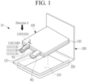
- FIG. 1 is a perspective view illustrating an electrode assembly and a case separated in a rechargeable battery according to embodiments of the present disclosure
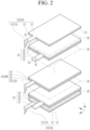
- FIG. 2 is an exploded perspective view illustrating the electrode assembly of FIG. 1
- FIG. 3 is a top plan view of the portion where a first electrode base tab is positioned in the electrode assembly of FIG. 1 as viewed from direction A.
- a rechargeable battery 10 includes an electrode assembly 100 and a case 200.
- the electrode assembly 100 includes a plurality of electrode plates 110 and 120 and a separator 130.
- Each of the electrode plates 110 and 120 include electrode base tabs 111 and 121, and are disposed to be stacked on one another.
- the first electrode plate 110 may include a first electrode base tab 111. There may be a plurality of first electrode plates 110, and there also may be a plurality of first electrode base tabs 111.
- the plurality of first electrode base tabs 111 may be joined to one other, such as by welding.
- the plurality of first electrode base tabs 111 may be assembled and joined together by welding, such as by any of laser welding, resistance welding, and ultrasonic welding.
- the second electrode plate 120 may include a second electrode base tab 121. If the electrode assembly 100 is of a stacked type, the first electrode plate 110 and the second electrode plate 120 may be stacked alternately, and the second electrode plate 120 may include a plurality of second electrode plates. There may also be a plurality of the second electrode base tabs 121. Like the first electrode base tab 111, the plurality of second electrode base tabs 121 may be joined to one another, such as by using various methods of welding.
- the above-described second electrode plate 120 may include a negative electrode, and the first electrode plate 110 may include a positive electrode, and vice versa.
- the first electrode plate 110 and the second electrode plate 120 may be electrically connected to an outside of the rechargeable battery 10 through a strip terminal (not shown).
- first electrode plate 110 will be described herein as a positive electrode and the second electrode plate 120 as a negative electrode, but the concepts are not so limited.
- a method of manufacturing the first electrode plate 110 may, for example, include pressing the first electrode current collector 112 with a press, thereby generating the first electrode base tab 111in a certain desired shape, such as a rectangular shape.
- the first electrode base tab 111 When a plurality of first electrode base tabs 111 are disposed, the first electrode base tab 111 may be defined as a multi-tab arrangement.
- the first electrode base tab 111 may be a path for current flow between the first electrode current collector 112 and a strip terminal (not shown).
- the second electrode plate 120 as a negative electrode, may be formed by applying a second electrode active material 123, such as graphite or carbon, to the second electrode current collector 122, itself formed of a metal foil such as copper, copper alloy, nickel or nickel alloy.
- the second electrode base tab 121 may extend outwardly from the second electrode current collector 122.
- a method of manufacturing the second electrode plate 120 may include pressing the second electrode current collector 122 with a press, thereby generating the second electrode base tab 121 in a desired shape, such as a rectangular shape.
- the separator 130 may be interposed between the first electrode plate 110 and the second electrode plate 120.
- the separator 130 prevents shorting between the first electrode plate 110 and the second electrode plate 120, and enables movement of lithium ions.
- the separator 130 may be larger in size than that of the first electrode plate 110 and that of the second electrode plate 120.
- the material of the separator 130 may be, for example, polyethylene, polypropylene, or a composite film of polyethylene and polypropylene, but is not limited thereto.
- Separator 130 may be cut into unit lengths and disposed between the first electrode plate 110 and the second electrode plate 120. Alternatively, a single separator 130 in a ribbon shape may be disposed between the first electrode plate 110 and the second electrode plate 120, creating a zigzag shape. Alternatively, separator 130 may be wound in one direction between the first electrode plate 110 and the second electrode plate 120. As such, the arrangement form of the separator 130 is not limited to a specific form.
- Case 200 may accommodate the electrode assembly 100, together with the electrolyte solution.
- Case 200 may be one of a pouch type, a cylindrical type, and a square type.
- Case 200 may be manufactured by bending plate-shaped exterior materials to face one another, pressing or drawing one side, and including a recess 210 on one side.
- the electrode assembly 100 may be accommodated in the recess 210.
- a sealing portion 220 may be formed on the outer periphery of the recess 210, and while the electrode assembly 100 is accommodated in the recess 210, the sealing portion 220 is sealed using a method such as thermal fusion.
- the manufacturing process of the electrode assembly 100 described above may include a first stacking step and a second stacking step.
- a full cathode which includes the remainder of the first electrode plate 110, excluding the outermost first electrode plate 110A, and a full anode, which includes the second electrode plate 120, may be stacked.
- a half cathode may be stacked on one or more of both outermost sides based on the stacking direction.
- the half cathode may include the outermost first electrode plate 110A among the first electrode plates 110.
- FIG. 1 illustrates the electrode assembly 100 in which the half cathode is stacked on both the upper and lower outermost sides of the electrode assembly 100.
- the half cathode it is also possible for the half cathode to be stacked only on the upper outermost electrode assembly 100, while the half anode is stacked on the lower outermost electrode assembly 100.
- the full cathode and the full anode have the active material applied to both sides of the base, and the half cathode has the active material applied to only one side of the base, but the concepts are not so limited.
- the second electrode plate 120 may be positioned on the upper and lower outermost sides of the electrode assembly 100.
- first electrode plate 110 may be positioned on the upper outermost side of the electrode assembly 100, and for the second electrode plate 120 to be positioned on the lower outermost side of the electrode assembly 100, although not shown.
- second electrode plate 120 it may be possible for the second electrode plate 120 to be positioned on the upper outermost side of the electrode assembly 100, and for the first electrode plate 120 to be positioned on the lower outermost side of the electrode assembly 100.
- the electrode base tab of the outermost electrode plate may be positioned in the inner region of the electrode base tabs of the remaining electrode plates, which plates are connected to one another.
- the first electrode base tab 111A of the first electrode plate 110A positioned on the outermost side among the plurality of first electrode plates 110, may be positioned in the inner region of the first electrode base tab 111B of the remaining first electrode plate 110B.
Landscapes
- Chemical & Material Sciences (AREA)
- Chemical Kinetics & Catalysis (AREA)
- Electrochemistry (AREA)
- General Chemical & Material Sciences (AREA)
- Engineering & Computer Science (AREA)
- Manufacturing & Machinery (AREA)
- Connection Of Batteries Or Terminals (AREA)
- Secondary Cells (AREA)
Applications Claiming Priority (1)
| Application Number | Priority Date | Filing Date | Title |
|---|---|---|---|
| KR1020230113032A KR20250031494A (ko) | 2023-08-28 | 2023-08-28 | 이차 전지 |
Publications (3)
| Publication Number | Publication Date |
|---|---|
| EP4517896A2 true EP4517896A2 (de) | 2025-03-05 |
| EP4517896A3 EP4517896A3 (de) | 2025-05-07 |
| EP4517896B1 EP4517896B1 (de) | 2025-12-17 |
Family
ID=92593056
Family Applications (1)
| Application Number | Title | Priority Date | Filing Date |
|---|---|---|---|
| EP24197042.5A Active EP4517896B1 (de) | 2023-08-28 | 2024-08-28 | Wiederaufladbare batterie |
Country Status (4)
| Country | Link |
|---|---|
| US (1) | US20250070410A1 (de) |
| EP (1) | EP4517896B1 (de) |
| KR (1) | KR20250031494A (de) |
| CN (1) | CN119542697A (de) |
Family Cites Families (6)
| Publication number | Priority date | Publication date | Assignee | Title |
|---|---|---|---|---|
| US9077027B2 (en) * | 2010-03-04 | 2015-07-07 | Samsung Sdi Co., Ltd. | Electrode assembly and secondary battery using the same |
| KR101254691B1 (ko) * | 2010-08-17 | 2013-04-15 | 주식회사 엘지화학 | 개선된 리드 구조의 이차전지 |
| JP5844052B2 (ja) * | 2011-02-04 | 2016-01-13 | 三洋電機株式会社 | 積層式電池およびその製造方法 |
| KR102125059B1 (ko) * | 2016-06-07 | 2020-06-19 | 주식회사 엘지화학 | 상호 결합된 극판 연장부들이 형성되어 있는 극판들을 포함하고 있는 전극조립체 |
| KR102264701B1 (ko) * | 2016-07-20 | 2021-06-11 | 삼성에스디아이 주식회사 | 이차전지 |
| KR101890844B1 (ko) * | 2017-11-24 | 2018-08-22 | 주식회사 리베스트 | 최외곽 전극의 구조 및 집전체의 재질에 의해 사용 안전성이 향상된 전극 조립체 및 상기 전극 조립체를 갖는 리튬이온 이차전지 |
-
2023
- 2023-08-28 KR KR1020230113032A patent/KR20250031494A/ko active Pending
-
2024
- 2024-08-26 US US18/814,940 patent/US20250070410A1/en active Pending
- 2024-08-28 CN CN202411187003.0A patent/CN119542697A/zh active Pending
- 2024-08-28 EP EP24197042.5A patent/EP4517896B1/de active Active
Also Published As
| Publication number | Publication date |
|---|---|
| CN119542697A (zh) | 2025-02-28 |
| EP4517896A3 (de) | 2025-05-07 |
| KR20250031494A (ko) | 2025-03-07 |
| US20250070410A1 (en) | 2025-02-27 |
| EP4517896B1 (de) | 2025-12-17 |
Similar Documents
| Publication | Publication Date | Title |
|---|---|---|
| US20250025957A1 (en) | Electrode Having Improved Electrode Tab Welding Characteristics and Secondary Battery Comprising the Same | |
| JP7694432B2 (ja) | 二次電池 | |
| US8236441B2 (en) | Battery cell design and methods of its construction | |
| KR101310176B1 (ko) | 축전 디바이스 및 그 제조방법 | |
| CN100541881C (zh) | 低阻抗分层电池设备及其制造方法 | |
| US8530068B2 (en) | Square battery and manufacturing method of the same | |
| KR102780825B1 (ko) | 이차 전지 및 그의 제조 방법 | |
| KR101072681B1 (ko) | 적층형 이차 전지 | |
| JP2006156401A (ja) | 二次電池 | |
| US20220352606A1 (en) | Secondary battery and method for manufacturing same | |
| US20110076544A1 (en) | Stack type battery | |
| JP2025063328A (ja) | 二次電池 | |
| JP7299816B2 (ja) | 積層型電池の製造方法、積層型電池の製造装置、及び積層型電池 | |
| KR101486623B1 (ko) | 파우치형 이차전지 및 이의 제조방법 | |
| JP2018041818A (ja) | 蓄電デバイス、蓄電モジュール、及び、蓄電モジュールの製造方法 | |
| EP4517896B1 (de) | Wiederaufladbare batterie | |
| JP7808280B2 (ja) | 蓄電装置、及び蓄電装置の製造方法 | |
| JP7285817B2 (ja) | 密閉型電池および密閉型電池の製造方法 | |
| KR102108208B1 (ko) | 원형 전극을 포함하는 원통형 이차전지 | |
| US20250087834A1 (en) | Electrode assembly and rechargeable battery including the same | |
| JP2010027494A (ja) | 蓄電デバイスおよびその製造方法 | |
| KR102261720B1 (ko) | 레이저 조사로 표면처리 된 전극집전체를 포함하는 전지셀 | |
| US20260051633A1 (en) | Secondary Battery and Manufacturing Method Thereof | |
| JP6285513B1 (ja) | 蓄電モジュール | |
| KR102803517B1 (ko) | 이차전지 |
Legal Events
| Date | Code | Title | Description |
|---|---|---|---|
| PUAI | Public reference made under article 153(3) epc to a published international application that has entered the european phase |
Free format text: ORIGINAL CODE: 0009012 |
|
| STAA | Information on the status of an ep patent application or granted ep patent |
Free format text: STATUS: REQUEST FOR EXAMINATION WAS MADE |
|
| 17P | Request for examination filed |
Effective date: 20240828 |
|
| AK | Designated contracting states |
Kind code of ref document: A2 Designated state(s): AL AT BE BG CH CY CZ DE DK EE ES FI FR GB GR HR HU IE IS IT LI LT LU LV MC ME MK MT NL NO PL PT RO RS SE SI SK SM TR |
|
| PUAL | Search report despatched |
Free format text: ORIGINAL CODE: 0009013 |
|
| AK | Designated contracting states |
Kind code of ref document: A3 Designated state(s): AL AT BE BG CH CY CZ DE DK EE ES FI FR GB GR HR HU IE IS IT LI LT LU LV MC ME MK MT NL NO PL PT RO RS SE SI SK SM TR |
|
| RIC1 | Information provided on ipc code assigned before grant |
Ipc: H01M 10/04 20060101AFI20250331BHEP |
|
| GRAP | Despatch of communication of intention to grant a patent |
Free format text: ORIGINAL CODE: EPIDOSNIGR1 |
|
| STAA | Information on the status of an ep patent application or granted ep patent |
Free format text: STATUS: GRANT OF PATENT IS INTENDED |
|
| INTG | Intention to grant announced |
Effective date: 20250819 |
|
| GRAS | Grant fee paid |
Free format text: ORIGINAL CODE: EPIDOSNIGR3 |
|
| GRAA | (expected) grant |
Free format text: ORIGINAL CODE: 0009210 |
|
| STAA | Information on the status of an ep patent application or granted ep patent |
Free format text: STATUS: THE PATENT HAS BEEN GRANTED |
|
| AK | Designated contracting states |
Kind code of ref document: B1 Designated state(s): AL AT BE BG CH CY CZ DE DK EE ES FI FR GB GR HR HU IE IS IT LI LT LU LV MC ME MK MT NL NO PL PT RO RS SE SI SK SM TR |
|
| REG | Reference to a national code |
Ref country code: CH Ref legal event code: F10 Free format text: ST27 STATUS EVENT CODE: U-0-0-F10-F00 (AS PROVIDED BY THE NATIONAL OFFICE) Effective date: 20251217 Ref country code: GB Ref legal event code: FG4D |
|
| REG | Reference to a national code |
Ref country code: DE Ref legal event code: R096 Ref document number: 602024001733 Country of ref document: DE |
|
| REG | Reference to a national code |
Ref country code: LT Ref legal event code: MG9D |
|
| PG25 | Lapsed in a contracting state [announced via postgrant information from national office to epo] |
Ref country code: NO Free format text: LAPSE BECAUSE OF FAILURE TO SUBMIT A TRANSLATION OF THE DESCRIPTION OR TO PAY THE FEE WITHIN THE PRESCRIBED TIME-LIMIT Effective date: 20260317 |
|
| PG25 | Lapsed in a contracting state [announced via postgrant information from national office to epo] |
Ref country code: FI Free format text: LAPSE BECAUSE OF FAILURE TO SUBMIT A TRANSLATION OF THE DESCRIPTION OR TO PAY THE FEE WITHIN THE PRESCRIBED TIME-LIMIT Effective date: 20251217 Ref country code: HR Free format text: LAPSE BECAUSE OF FAILURE TO SUBMIT A TRANSLATION OF THE DESCRIPTION OR TO PAY THE FEE WITHIN THE PRESCRIBED TIME-LIMIT Effective date: 20251217 |
|
| PG25 | Lapsed in a contracting state [announced via postgrant information from national office to epo] |
Ref country code: RS Free format text: LAPSE BECAUSE OF FAILURE TO SUBMIT A TRANSLATION OF THE DESCRIPTION OR TO PAY THE FEE WITHIN THE PRESCRIBED TIME-LIMIT Effective date: 20260317 |
|
| REG | Reference to a national code |
Ref country code: NL Ref legal event code: MP Effective date: 20251217 |
|
| PG25 | Lapsed in a contracting state [announced via postgrant information from national office to epo] |
Ref country code: LV Free format text: LAPSE BECAUSE OF FAILURE TO SUBMIT A TRANSLATION OF THE DESCRIPTION OR TO PAY THE FEE WITHIN THE PRESCRIBED TIME-LIMIT Effective date: 20251217 |