EP4517895A2 - Batterie und batteriepack - Google Patents
Batterie und batteriepack Download PDFInfo
- Publication number
- EP4517895A2 EP4517895A2 EP24196791.8A EP24196791A EP4517895A2 EP 4517895 A2 EP4517895 A2 EP 4517895A2 EP 24196791 A EP24196791 A EP 24196791A EP 4517895 A2 EP4517895 A2 EP 4517895A2
- Authority
- EP
- European Patent Office
- Prior art keywords
- current collector
- case
- collector plate
- battery according
- upper cover
- Prior art date
- Legal status (The legal status is an assumption and is not a legal conclusion. Google has not performed a legal analysis and makes no representation as to the accuracy of the status listed.)
- Pending
Links
Images




Classifications
-
- H—ELECTRICITY
- H01—ELECTRIC ELEMENTS
- H01M—PROCESSES OR MEANS, e.g. BATTERIES, FOR THE DIRECT CONVERSION OF CHEMICAL ENERGY INTO ELECTRICAL ENERGY
- H01M50/00—Constructional details or processes of manufacture of the non-active parts of electrochemical cells other than fuel cells, e.g. hybrid cells
- H01M50/50—Current conducting connections for cells or batteries
- H01M50/531—Electrode connections inside a battery casing
- H01M50/538—Connection of several leads or tabs of wound or folded electrode stacks
-
- H—ELECTRICITY
- H01—ELECTRIC ELEMENTS
- H01M—PROCESSES OR MEANS, e.g. BATTERIES, FOR THE DIRECT CONVERSION OF CHEMICAL ENERGY INTO ELECTRICAL ENERGY
- H01M50/00—Constructional details or processes of manufacture of the non-active parts of electrochemical cells other than fuel cells, e.g. hybrid cells
- H01M50/10—Primary casings; Jackets or wrappings
- H01M50/102—Primary casings; Jackets or wrappings characterised by their shape or physical structure
- H01M50/112—Monobloc comprising multiple compartments
-
- H—ELECTRICITY
- H01—ELECTRIC ELEMENTS
- H01M—PROCESSES OR MEANS, e.g. BATTERIES, FOR THE DIRECT CONVERSION OF CHEMICAL ENERGY INTO ELECTRICAL ENERGY
- H01M10/00—Secondary cells; Manufacture thereof
- H01M10/04—Construction or manufacture in general
- H01M10/0431—Cells with wound or folded electrodes
-
- H—ELECTRICITY
- H01—ELECTRIC ELEMENTS
- H01M—PROCESSES OR MEANS, e.g. BATTERIES, FOR THE DIRECT CONVERSION OF CHEMICAL ENERGY INTO ELECTRICAL ENERGY
- H01M10/00—Secondary cells; Manufacture thereof
- H01M10/05—Accumulators with non-aqueous electrolyte
- H01M10/058—Construction or manufacture
- H01M10/0587—Construction or manufacture of accumulators having only wound construction elements, i.e. wound positive electrodes, wound negative electrodes and wound separators
-
- H—ELECTRICITY
- H01—ELECTRIC ELEMENTS
- H01M—PROCESSES OR MEANS, e.g. BATTERIES, FOR THE DIRECT CONVERSION OF CHEMICAL ENERGY INTO ELECTRICAL ENERGY
- H01M50/00—Constructional details or processes of manufacture of the non-active parts of electrochemical cells other than fuel cells, e.g. hybrid cells
- H01M50/10—Primary casings; Jackets or wrappings
- H01M50/102—Primary casings; Jackets or wrappings characterised by their shape or physical structure
-
- H—ELECTRICITY
- H01—ELECTRIC ELEMENTS
- H01M—PROCESSES OR MEANS, e.g. BATTERIES, FOR THE DIRECT CONVERSION OF CHEMICAL ENERGY INTO ELECTRICAL ENERGY
- H01M50/00—Constructional details or processes of manufacture of the non-active parts of electrochemical cells other than fuel cells, e.g. hybrid cells
- H01M50/10—Primary casings; Jackets or wrappings
- H01M50/102—Primary casings; Jackets or wrappings characterised by their shape or physical structure
- H01M50/107—Primary casings; Jackets or wrappings characterised by their shape or physical structure having curved cross-section, e.g. round or elliptic
-
- H—ELECTRICITY
- H01—ELECTRIC ELEMENTS
- H01M—PROCESSES OR MEANS, e.g. BATTERIES, FOR THE DIRECT CONVERSION OF CHEMICAL ENERGY INTO ELECTRICAL ENERGY
- H01M50/00—Constructional details or processes of manufacture of the non-active parts of electrochemical cells other than fuel cells, e.g. hybrid cells
- H01M50/10—Primary casings; Jackets or wrappings
- H01M50/131—Primary casings; Jackets or wrappings characterised by physical properties, e.g. gas permeability, size or heat resistance
-
- H—ELECTRICITY
- H01—ELECTRIC ELEMENTS
- H01M—PROCESSES OR MEANS, e.g. BATTERIES, FOR THE DIRECT CONVERSION OF CHEMICAL ENERGY INTO ELECTRICAL ENERGY
- H01M50/00—Constructional details or processes of manufacture of the non-active parts of electrochemical cells other than fuel cells, e.g. hybrid cells
- H01M50/10—Primary casings; Jackets or wrappings
- H01M50/14—Primary casings; Jackets or wrappings for protecting against damage caused by external factors
- H01M50/143—Fireproof; Explosion-proof
-
- H—ELECTRICITY
- H01—ELECTRIC ELEMENTS
- H01M—PROCESSES OR MEANS, e.g. BATTERIES, FOR THE DIRECT CONVERSION OF CHEMICAL ENERGY INTO ELECTRICAL ENERGY
- H01M50/00—Constructional details or processes of manufacture of the non-active parts of electrochemical cells other than fuel cells, e.g. hybrid cells
- H01M50/10—Primary casings; Jackets or wrappings
- H01M50/147—Lids or covers
- H01M50/148—Lids or covers characterised by their shape
- H01M50/152—Lids or covers characterised by their shape for cells having curved cross-section, e.g. round or elliptic
-
- H—ELECTRICITY
- H01—ELECTRIC ELEMENTS
- H01M—PROCESSES OR MEANS, e.g. BATTERIES, FOR THE DIRECT CONVERSION OF CHEMICAL ENERGY INTO ELECTRICAL ENERGY
- H01M50/00—Constructional details or processes of manufacture of the non-active parts of electrochemical cells other than fuel cells, e.g. hybrid cells
- H01M50/20—Mountings; Secondary casings or frames; Racks, modules or packs; Suspension devices; Shock absorbers; Transport or carrying devices; Holders
- H01M50/204—Racks, modules or packs for multiple batteries or multiple cells
- H01M50/207—Racks, modules or packs for multiple batteries or multiple cells characterised by their shape
- H01M50/213—Racks, modules or packs for multiple batteries or multiple cells characterised by their shape adapted for cells having curved cross-section, e.g. round or elliptic
-
- H—ELECTRICITY
- H01—ELECTRIC ELEMENTS
- H01M—PROCESSES OR MEANS, e.g. BATTERIES, FOR THE DIRECT CONVERSION OF CHEMICAL ENERGY INTO ELECTRICAL ENERGY
- H01M50/00—Constructional details or processes of manufacture of the non-active parts of electrochemical cells other than fuel cells, e.g. hybrid cells
- H01M50/30—Arrangements for facilitating escape of gases
- H01M50/342—Non-re-sealable arrangements
- H01M50/3425—Non-re-sealable arrangements in the form of rupturable membranes or weakened parts, e.g. pierced with the aid of a sharp member
-
- H—ELECTRICITY
- H01—ELECTRIC ELEMENTS
- H01M—PROCESSES OR MEANS, e.g. BATTERIES, FOR THE DIRECT CONVERSION OF CHEMICAL ENERGY INTO ELECTRICAL ENERGY
- H01M50/00—Constructional details or processes of manufacture of the non-active parts of electrochemical cells other than fuel cells, e.g. hybrid cells
- H01M50/50—Current conducting connections for cells or batteries
- H01M50/531—Electrode connections inside a battery casing
- H01M50/533—Electrode connections inside a battery casing characterised by the shape of the leads or tabs
-
- H—ELECTRICITY
- H01—ELECTRIC ELEMENTS
- H01M—PROCESSES OR MEANS, e.g. BATTERIES, FOR THE DIRECT CONVERSION OF CHEMICAL ENERGY INTO ELECTRICAL ENERGY
- H01M50/00—Constructional details or processes of manufacture of the non-active parts of electrochemical cells other than fuel cells, e.g. hybrid cells
- H01M50/50—Current conducting connections for cells or batteries
- H01M50/531—Electrode connections inside a battery casing
- H01M50/536—Electrode connections inside a battery casing characterised by the method of fixing the leads to the electrodes, e.g. by welding
-
- H—ELECTRICITY
- H01—ELECTRIC ELEMENTS
- H01M—PROCESSES OR MEANS, e.g. BATTERIES, FOR THE DIRECT CONVERSION OF CHEMICAL ENERGY INTO ELECTRICAL ENERGY
- H01M50/00—Constructional details or processes of manufacture of the non-active parts of electrochemical cells other than fuel cells, e.g. hybrid cells
- H01M50/50—Current conducting connections for cells or batteries
- H01M50/543—Terminals
- H01M50/564—Terminals characterised by their manufacturing process
- H01M50/566—Terminals characterised by their manufacturing process by welding, soldering or brazing
-
- Y—GENERAL TAGGING OF NEW TECHNOLOGICAL DEVELOPMENTS; GENERAL TAGGING OF CROSS-SECTIONAL TECHNOLOGIES SPANNING OVER SEVERAL SECTIONS OF THE IPC; TECHNICAL SUBJECTS COVERED BY FORMER USPC CROSS-REFERENCE ART COLLECTIONS [XRACs] AND DIGESTS
- Y02—TECHNOLOGIES OR APPLICATIONS FOR MITIGATION OR ADAPTATION AGAINST CLIMATE CHANGE
- Y02E—REDUCTION OF GREENHOUSE GAS [GHG] EMISSIONS, RELATED TO ENERGY GENERATION, TRANSMISSION OR DISTRIBUTION
- Y02E60/00—Enabling technologies; Technologies with a potential or indirect contribution to GHG emissions mitigation
- Y02E60/10—Energy storage using batteries
-
- Y—GENERAL TAGGING OF NEW TECHNOLOGICAL DEVELOPMENTS; GENERAL TAGGING OF CROSS-SECTIONAL TECHNOLOGIES SPANNING OVER SEVERAL SECTIONS OF THE IPC; TECHNICAL SUBJECTS COVERED BY FORMER USPC CROSS-REFERENCE ART COLLECTIONS [XRACs] AND DIGESTS
- Y02—TECHNOLOGIES OR APPLICATIONS FOR MITIGATION OR ADAPTATION AGAINST CLIMATE CHANGE
- Y02P—CLIMATE CHANGE MITIGATION TECHNOLOGIES IN THE PRODUCTION OR PROCESSING OF GOODS
- Y02P70/00—Climate change mitigation technologies in the production process for final industrial or consumer products
- Y02P70/50—Manufacturing or production processes characterised by the final manufactured product
Definitions
- the present disclosure relates to the field of batteries, and in particular to a battery and a battery pack.
- a plurality of individual batteries are power-connected to each other by an external power connector to form a battery module, and subsequently, the battery is further assembled to form a battery pack.
- a frame and a structural component which is used to form the individual batteries into the battery module, has a certain mechanical strength and supports, fixes and protects each cell.
- a large number of mounting structures are used for forming the battery module and the battery pack, and therefore, costs of the battery pack are higher, and an overall weight of the battery pack is increased.
- the mounting structures occupy more spaces, resulting the power battery pack having a reduced capacity for each cell, such that an energy density is lower.
- the present application discloses a battery and a battery pack that are capable of increasing the number and capacities of cells and effectively increasing the battery energy density.
- the present disclosure provides a battery, including: at least two jellyrolls; and a case.
- the at least two jellyrolls are disposed in the case, the case is arranged with at least two extension portions around a central axis of the case, and the at least two extension portions are communicated with each other.
- Each of the at least two extension portions is filled by a respective one of the at least two jellyrolls; the number of the at least two extension portions is equal to the number of the at least two jellyrolls.
- one case is filled with the plurality of jellyrolls.
- One case can protect the plurality of jellyrolls, effectively improving the battery energy density and reducing the number of structural components.
- the number of the at least two extension portions is 2 to 6.
- the case includes a case body and an upper cover; the case body is arranged with the at least two extension portions; the upper cover is disposed at an end surface of each jellyroll.
- the battery further includes two current collector plates arranged inside the case.
- a plane on which an end face of each of the two current collector plates is located is parallel to a plane on which an end face of the upper cover is located.
- the two current collector plates are a first current collector plate and a second current collector plate; the first current collector plate is disposed at an end of the jellyroll and is welded to a tab arranged on the end of the jellyroll, and the second current collector plate is disposed at the other end of the jellyroll and is welded to another tab arranged on the other end of the jellyroll.
- a pole is arranged on the upper cover; one of the two current collector plates that is disposed near the upper cover is welded to the pole.
- the one of the two current collector plates disposed near the upper cover is arranged with a protrusion, protruding towards the pole; and the protrusion is welded with the pole.
- one of the two current collector plates disposed away from the upper cover has a vertical edge; and the vertical edge is welded with a side wall of the case body.
- a length H of the vertical edge is in a range of 0.5mm ⁇ H ⁇ 2mm.
- a thickness T of the protrusion is in a range of 0.1 mm ⁇ T ⁇ 0.6 mm.
- the at least two jellyrolls that are disposed in one case are connected to each other in parallel.
- the battery further includes a cap.
- the case body has two openings at two ends thereof, respectively.
- the cap covers a side of the case body away from the upper cover and covers a respective one of the two openings; the first current collector plate is disposed near the upper cover; the second current collector plate is disposed near the cap; a side of the cap facing towards the second current collector plate is arranged with a reinforcing rib; the reinforcing rib at least partially abuts against the second current collector plate.
- a gap is defined between the second current collector plate and a portion of the cap that is not arranged with the reinforcing rib; and a distance D of the gap is in a range of 0.2 mm ⁇ D ⁇ 0.7 mm.
- a side of the cap away from the second current collector plate is arranged with an explosion-proof mark.
- a thickness of a portion of the cap arranged with the explosion-proof mark is in a range of 0.05mm to 0.12mm.
- the present disclosure provides a battery pack, including a plurality of batteries, wherein, each of the plurality of batteries is the battery as described in the above aspect.
- the plurality of batteries are arranged in a plurality of columns, and batteries in adjacent two columns of the plurality of columns are spaced apart from each other.
- orientation terms such as “up”, “down”, “inside”, “outside”, and so on are described based on what is shown in the accompanying drawings and shall not be understood as limiting the specific embodiment.
- orientation terms such as “up”, “down”, “inside”, “outside”, and so on are described based on what is shown in the accompanying drawings and shall not be understood as limiting the specific embodiment.
- orientation terms such as “up”, “down”, “inside”, “outside”, and so on are described based on what is shown in the accompanying drawings and shall not be understood as limiting the specific embodiment.
- orientation terms such as “up”, “down”, “inside”, “outside”, and so on are described based on what is shown in the accompanying drawings and shall not be understood as limiting the specific embodiment.
- orientation terms such as “up”, “down”, “inside”, “outside”, and so on are described based on what is shown in the accompanying drawings and shall not be understood as limiting the specific embodiment.
- orientation terms such as “up”, “down”, “inside”,
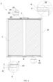
- the present disclosure provides a battery including a jellyroll 1 and a case 2.
- the jellyroll 1 is a cylindrical jellyroll 1 and is disposed in the case 2.
- the case 2 is arranged with at least two extension portions around a central axis of the case. Each extension portion is filled by one jellyroll 1.
- the number of extension portions is equal to the number of jellyrolls 1. Since a plurality of jellyrolls 1 are filled in the case 2, one case 2 protects the plurality of jellyrolls 1. Therefore, arranging one case 2 for each jellyroll 1 is not required, materials required to manufacture the case 2 are reduced, a weight of one battery is reduced. In addition, an energy density of the battery is effectively increased, the number of structural components is reduced. Since a plurality of extension portions are arranged, a surface heat-dissipation area of the battery is increased, facilitating thermal control and management of the battery pack.
- the number of the at least two extension portions is 2 to 6, and in the present embodiment, the battery is arranged with 3 extension portions and will be illustrated in the following.
- the battery of the present embodiment further includes two current collector plates arranged inside the case 2.
- the two current collector plates are a first current collector plate 3 and a second current collector plate 5.
- the jellyroll 1 is the cylindrical jellyroll.
- the first current collector plate 3 is welded to a tab leading out from a circular end surface of the jellyroll 1
- the second current collector plate 5 is welded to another tab leading out from the other circular end surface of the jellyroll 1.
- the case 2 includes a case body 21, an upper cover 22, an inner sealing ring 23, an outer sealing ring 24, and a pole 25.
- the case body 21 and the upper cover 22 are integrally molded as a one-piece structure.
- the case body 21 has two openings at two ends, respectively.
- the case body 21 has three extension portions.
- the upper cover 22 covers the end surface of the jellyroll 1.
- One of the first current collector plate 3 and the second current collector plate 5 is disposed in a semi-enclosed region formed by the case body 21 and the upper cover 22, and the other one of the first current collector plate 3 and the second current collector plate 5 is disposed at the end of the case body away from the upper cover 22.
- the pole 25 is arranged on the upper cover 22. Specifically, the first current collector plate 3 is disposed near the upper cover 22, and the second current collector plate 5 is welded to the other end of the jellyroll 1. The first current collector plate 3 and the second current collector plate 5 are respectively welded to two tabs of the jellyroll 1.
- the first current collector plate 3 is arranged with a protrusion (not shown in the drawings) protruding towards the pole 25.
- a thickness of the protrusion is T and is in a range of 0.1 mm ⁇ T ⁇ 0.6 mm. In this way, the pole 25 and the first current collector plate 3 can be welded to each other easily.
- An insulating gasket 4 is arranged between the upper cover 22 and the first current collector plate 3.
- a cap 6 is arranged at a bottom of the second current collector plate 6. The cap 6 is welded to the case 2.
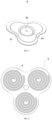
- the case 2 in the present embodiment is arranged with three extension portions.
- the three extension portions are extending outwardly to form a petal shape.
- a shape of the first current collector plate 3 and/or the second current collector plate 5 is the same as a shape of the upper cover 22.
- FIG. 6 shows welding imprints between the first current collector plate 3 and the jellyroll 1 of the present embodiment.
- a portion A in FIG. 6 is a welding trace to ensure that the first current collector plate 3 is welded to each of three jellyrolls 1.
- the first current collector plate 3 and the jellyrolls 1 are partially wrapped by a spacer adhesive paper, preventing the tab from touching, due to being flipped, the case 2, where the touching may result in a short circuit of the battery. Furthermore, the insulating gasket 4 is arranged inside the case 2 and is disposed between the upper cover 22 and the first current collector plate 3. The first current collector plate 3 and the jellyrolls 1 that are wrapped by the spacer adhesive paper are placed inside the case 2. A laser is applied to weld the pole 25 with to the protrusion of the first current collector plate 3. A welding direction is shown in FIG. 7 .
- the pole 25 is enabled to be conductive to a circuit of the first current collector plate 3, and then a pole sealing nail 7 is welded with the pole 25.
- a terminal side sealing is achieved.
- the inner sealing ring 23 and the outer sealing ring 24 are respectively arranged at two sides of the pole 25, further enhancing a sealing performance of the pole 25.
- the second current collector plate 5 has a vertical edge. The vertical edge is welded with a side wall of the case body 21 by a laser beam, and a welding direction thereof is shown in FIG. 8 . A length of the vertical edge is H in a range of 0.5mm ⁇ H ⁇ 2mm. Since the second current collector plate 5 and the case 2 are welded to each other, the case 2 is charged, and a conductive circuit is formed.
- the second current collector plate 5 and the cap 6 are not welded to each other, such that a conductive line is reduced, and a battery internal resistance is reduced.
- the battery in the present embodiment further includes the cap 6.
- the case body 21 defines two openings respectively at the two ends.
- the cap 6 covers the side of the case body 21 away from the upper cover 22 and covers one of the two openings. Peripheries of the cap 6 and the case 2 are welded to each other.
- the cap 6 defines a fluid-injection hole. Fluid, helium, and sealing adhesive particles are injected to an interior of the case 2 through the fluid-injection hole. A cap sealing nail 8 is then welded to completely seal the battery.
- the second current collector plate 5 is disposed near the cap 6.
- a side of the cap 6 facing the second current collector plate 5 is arranged with a reinforcing rib 61. At least a portion of the reinforcing rib 61 abuts against the second current collector plate 5 to compress the jellyroll 1 to prevent the jellyroll 1 from shaking.
- a portion of the cap 6 that is not arranged with any reinforcing rib 61 is spaced apart from the second current collector plate 5, i.e., a gap is defined therebetween. As shown in FIG. 2 , the gap is D in a range of 0.2mm ⁇ D ⁇ 0.7mm.
- the cap 6 is dis-conductive with the jellyroll 1 to reduce the conductive line and reduce the internal resistance of the battery.
- the cap 6 is further arranged with an explosion-proof mark 63.
- the explosion-proof mark 63 is located at the bottom of the case 2.
- a thickness of a portion of the cap 6 arranged with the explosion-proof mark 63 is in a range of 0.05mm-0.12mm, such that the battery is ensured to be used safely.
- the side of the case where the pole 25 is located serves as an output region
- the side of the case where the cap 6 is located serves as a functional region.
- the present disclosure further provides a battery pack including a plurally of batteries as described above.
- the plurally of batteries are directly assembled to each other to form the battery pack.
- the plurally of batteries do not need to form a battery module before being assembled into the battery pack. In this way, a space for arranging the batteries is saved, and energy of the battery pack is greatly enhanced.
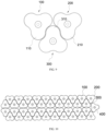
- the plurality of batteries are arranged into a plurality of columns. Batteries that are located at ends of two adjacent columns are spaced apart from each other. As shown in FIG. 9, FIG. 9 show three batteries having a same shape and a same size with each other. Each battery is arranged with three extension portions.
- the three batteries are denoted as a first integrator 100, a second integrator 200, and a third integrator 300, respectively.
- the first integrator 100 and the second integrator 200 are disposed in a same column.
- the third integrator 300 is embedded between the first integrator 100 and the second integrator 200.
- the first integrator 100 is arranged with a first extension portion 110
- the second integrator 200 is arranged with a second extension portion 210.
- a gap is defined between the first extension portion 110 and the second extension portion 210.
- the third integrator 300 is arranged with a third extension portion 310.
- the third extension portion 310 is received in the gap between the first extension portion 110 and the second extension portion 210. Two sides of the third extension portion 310 respectively abut against the first integrator and the second integrator 200.
- the battery pack further includes a fourth integrator 400.
- the fourth integrator 400 is disposed at an end of the column. Two extension portions of the fourth integrator 400 respectively abut against two extension portions of two third integrators 300 that are disposed symmetrical to each other. In this way, a space utilization rate is increased.
- the present disclosure provides a battery and a battery pack having at least the following technical effects.
- the plurality of jellyrolls 1 are filled in one case 2.
- the one case 2 can protect the plurality of jellyrolls 1. Therefore, the energy density of the battery is effectively increased, and the number of structural components is reduced.
- the plurality of batteries are directly assembled to form the battery pack.
- the plurality of batteries do not need to form a battery module before being assembled to form the battery pack. Therefore, a space for arranging the batteries is saved, and the energy of the battery pack is improved.
- the case 2 is arranged with 2 to 6 extension portions. Therefore, the surface heat-dissipation area of the battery is increased, facilitating the thermal control and management of the battery pack.
Landscapes
- Chemical & Material Sciences (AREA)
- Chemical Kinetics & Catalysis (AREA)
- Electrochemistry (AREA)
- General Chemical & Material Sciences (AREA)
- Engineering & Computer Science (AREA)
- Manufacturing & Machinery (AREA)
- Battery Mounting, Suspending (AREA)
- Primary Cells (AREA)
- Sealing Battery Cases Or Jackets (AREA)
- Gas Exhaust Devices For Batteries (AREA)
- Secondary Cells (AREA)
- Connection Of Batteries Or Terminals (AREA)
Applications Claiming Priority (1)
| Application Number | Priority Date | Filing Date | Title |
|---|---|---|---|
| CN202322371131.8U CN220829994U (zh) | 2023-08-31 | 2023-08-31 | 一种电池及电池包 |
Publications (2)
| Publication Number | Publication Date |
|---|---|
| EP4517895A2 true EP4517895A2 (de) | 2025-03-05 |
| EP4517895A3 EP4517895A3 (de) | 2025-04-30 |
Family
ID=90723738
Family Applications (1)
| Application Number | Title | Priority Date | Filing Date |
|---|---|---|---|
| EP24196791.8A Pending EP4517895A3 (de) | 2023-08-31 | 2024-08-27 | Batterie und batteriepack |
Country Status (7)
| Country | Link |
|---|---|
| US (1) | US20250079656A1 (de) |
| EP (1) | EP4517895A3 (de) |
| JP (1) | JP2025036260A (de) |
| KR (1) | KR20250033059A (de) |
| CN (1) | CN220829994U (de) |
| DE (1) | DE202024104953U1 (de) |
| WO (1) | WO2025044651A1 (de) |
Families Citing this family (1)
| Publication number | Priority date | Publication date | Assignee | Title |
|---|---|---|---|---|
| CN220829994U (zh) * | 2023-08-31 | 2024-04-23 | 湖北亿纬动力有限公司 | 一种电池及电池包 |
Family Cites Families (13)
| Publication number | Priority date | Publication date | Assignee | Title |
|---|---|---|---|---|
| CN101517773B (zh) * | 2006-10-24 | 2011-02-09 | 松下电器产业株式会社 | 密闭型二次电池 |
| DE102009033076B4 (de) * | 2009-07-03 | 2019-06-27 | Volkswagen Ag | Verfahren zur Anordnung von zylinderförmigen Batteriezellen zu einem Batteriemodul für ein Fahrzeug sowie entsprechend ausgestaltete(s) Batteriemodul, Batteriemodulanordnung und Fahrzeug |
| CN202395102U (zh) * | 2011-12-19 | 2012-08-22 | 深圳市慧通天下科技股份有限公司 | 类圆柱锂离子电池 |
| JP2017220324A (ja) * | 2016-06-06 | 2017-12-14 | 株式会社Gsユアサ | 蓄電素子 |
| CN209981391U (zh) * | 2019-04-16 | 2020-01-21 | 浙江天能能源科技股份有限公司 | 一种高容量圆柱电池 |
| US11489211B2 (en) * | 2019-06-20 | 2022-11-01 | Apple Inc. | Asymmetric battery pack with varied electrode and current collector properties to achieve C-Rate balancing |
| CN112290128A (zh) * | 2020-10-20 | 2021-01-29 | 合肥国轩高科动力能源有限公司 | 一种多卷芯锂离子电池及电池包 |
| DE102021122486A1 (de) * | 2021-08-31 | 2023-03-02 | Bayerische Motoren Werke Aktiengesellschaft | Gehäuse für Elektrodenstapel und Batteriezellengruppe |
| EP4398384A4 (de) * | 2022-01-26 | 2025-06-25 | Contemporary Amperex Technology (Hong Kong) Limited | Batteriezelle und batterie |
| CN217035800U (zh) * | 2022-03-28 | 2022-07-22 | 蓝京新能源(嘉兴)有限公司 | 一种多极耳圆柱电池 |
| CN115513514B (zh) * | 2022-09-06 | 2025-02-11 | 天津力神电池股份有限公司 | 一种单体电池及其制备方法 |
| CN219350313U (zh) * | 2022-11-28 | 2023-07-14 | 欣旺达电动汽车电池有限公司 | 单体电池及电池包 |
| CN220829994U (zh) * | 2023-08-31 | 2024-04-23 | 湖北亿纬动力有限公司 | 一种电池及电池包 |
-
2023
- 2023-08-31 CN CN202322371131.8U patent/CN220829994U/zh active Active
-
2024
- 2024-07-30 WO PCT/CN2024/108424 patent/WO2025044651A1/zh active Pending
- 2024-08-27 EP EP24196791.8A patent/EP4517895A3/de active Pending
- 2024-08-27 JP JP2024145071A patent/JP2025036260A/ja active Pending
- 2024-08-28 KR KR1020240116172A patent/KR20250033059A/ko active Pending
- 2024-08-30 US US18/820,269 patent/US20250079656A1/en active Pending
- 2024-08-30 DE DE202024104953.5U patent/DE202024104953U1/de active Active
Also Published As
| Publication number | Publication date |
|---|---|
| CN220829994U (zh) | 2024-04-23 |
| KR20250033059A (ko) | 2025-03-07 |
| WO2025044651A1 (zh) | 2025-03-06 |
| DE202024104953U1 (de) | 2024-10-02 |
| EP4517895A3 (de) | 2025-04-30 |
| US20250079656A1 (en) | 2025-03-06 |
| JP2025036260A (ja) | 2025-03-14 |
Similar Documents
| Publication | Publication Date | Title |
|---|---|---|
| JP6090711B2 (ja) | 2次電池及び電池モジュール | |
| EP2228852B1 (de) | Wiederaufladbare Batterie mit Stromsammlerplatten mit verbesserter Struktur | |
| JP4484782B2 (ja) | 二次電池 | |
| CN100364141C (zh) | 密封型蓄电池和电池模块 | |
| CN210576107U (zh) | 电池模组、电池包以及车辆 | |
| EP3555935B1 (de) | Batteriemodulgehäuse, batteriemodul und batterie | |
| US20220200110A1 (en) | Secondary battery | |
| EP4517895A2 (de) | Batterie und batteriepack | |
| KR20230008817A (ko) | 배터리, 배터리 팩, 및 차량 | |
| KR20230011373A (ko) | 셀 어셈블리, 배터리, 배터리 팩, 및 차량 | |
| CN114639926A (zh) | 电池及电池的装配方法 | |
| EP2830121B1 (de) | Wiederaufladbare Batterie | |
| CN114024082A (zh) | 电池、电池模组以及电池包 | |
| CN209401692U (zh) | 二次电池 | |
| CN212967878U (zh) | 单体电池转接片、单体电池及动力电池组 | |
| JP4114030B2 (ja) | 電池モジュール及び扁平形状電池 | |
| KR20230010247A (ko) | 배터리, 배터리 팩, 및 자동차 | |
| WO2024179190A1 (zh) | 端盖组件、电池和储能装置 | |
| CN217589344U (zh) | 电池 | |
| US20220216545A1 (en) | Flat secondary battery | |
| CN210040381U (zh) | 电池单体及电池组及电池组件 | |
| CN223712879U (zh) | 一种壳体及电池 | |
| CN223427696U (zh) | 一种电芯模组及电池 | |
| CN224191045U (zh) | 一种盖板结构、电池、电池包及用电设备 | |
| CN223260688U (zh) | 一种电池外壳及电池 |
Legal Events
| Date | Code | Title | Description |
|---|---|---|---|
| PUAI | Public reference made under article 153(3) epc to a published international application that has entered the european phase |
Free format text: ORIGINAL CODE: 0009012 |
|
| STAA | Information on the status of an ep patent application or granted ep patent |
Free format text: STATUS: REQUEST FOR EXAMINATION WAS MADE |
|
| 17P | Request for examination filed |
Effective date: 20240827 |
|
| AK | Designated contracting states |
Kind code of ref document: A2 Designated state(s): AL AT BE BG CH CY CZ DE DK EE ES FI FR GB GR HR HU IE IS IT LI LT LU LV MC ME MK MT NL NO PL PT RO RS SE SI SK SM TR |
|
| PUAL | Search report despatched |
Free format text: ORIGINAL CODE: 0009013 |
|
| AK | Designated contracting states |
Kind code of ref document: A3 Designated state(s): AL AT BE BG CH CY CZ DE DK EE ES FI FR GB GR HR HU IE IS IT LI LT LU LV MC ME MK MT NL NO PL PT RO RS SE SI SK SM TR |
|
| RIC1 | Information provided on ipc code assigned before grant |
Ipc: H01M 50/538 20210101ALI20250326BHEP Ipc: H01M 50/342 20210101ALI20250326BHEP Ipc: H01M 50/143 20210101ALI20250326BHEP Ipc: H01M 50/131 20210101ALI20250326BHEP Ipc: H01M 50/112 20210101ALI20250326BHEP Ipc: H01M 50/107 20210101ALI20250326BHEP Ipc: H01M 50/102 20210101ALI20250326BHEP Ipc: H01M 10/04 20060101AFI20250326BHEP |