EP4516686A1 - Heiz-heraufzug verhindernder flaschenverschluss und befestigungsstruktur für den inneren hauptkörper eines flaschenverschlusses und flaschenhals - Google Patents
Heiz-heraufzug verhindernder flaschenverschluss und befestigungsstruktur für den inneren hauptkörper eines flaschenverschlusses und flaschenhals Download PDFInfo
- Publication number
- EP4516686A1 EP4516686A1 EP24795667.5A EP24795667A EP4516686A1 EP 4516686 A1 EP4516686 A1 EP 4516686A1 EP 24795667 A EP24795667 A EP 24795667A EP 4516686 A1 EP4516686 A1 EP 4516686A1
- Authority
- EP
- European Patent Office
- Prior art keywords
- fixing sleeve
- bottle
- rotation
- bottle cap
- wall
- Prior art date
- Legal status (The legal status is an assumption and is not a legal conclusion. Google has not performed a legal analysis and makes no representation as to the accuracy of the status listed.)
- Pending
Links
Images






Classifications
-
- B—PERFORMING OPERATIONS; TRANSPORTING
- B65—CONVEYING; PACKING; STORING; HANDLING THIN OR FILAMENTARY MATERIAL
- B65D—CONTAINERS FOR STORAGE OR TRANSPORT OF ARTICLES OR MATERIALS, e.g. BAGS, BARRELS, BOTTLES, BOXES, CANS, CARTONS, CRATES, DRUMS, JARS, TANKS, HOPPERS, FORWARDING CONTAINERS; ACCESSORIES, CLOSURES, OR FITTINGS THEREFOR; PACKAGING ELEMENTS; PACKAGES
- B65D41/00—Caps, e.g. crown caps or crown seals, i.e. members having parts arranged for engagement with the external periphery of a neck or wall defining a pouring opening or discharge aperture; Protective cap-like covers for closure members, e.g. decorative covers of metal foil or paper
- B65D41/02—Caps or cap-like covers without lines of weakness, tearing strips, tags, or like opening or removal devices
- B65D41/28—Caps combined with stoppers
-
- B—PERFORMING OPERATIONS; TRANSPORTING
- B65—CONVEYING; PACKING; STORING; HANDLING THIN OR FILAMENTARY MATERIAL
- B65D—CONTAINERS FOR STORAGE OR TRANSPORT OF ARTICLES OR MATERIALS, e.g. BAGS, BARRELS, BOTTLES, BOXES, CANS, CARTONS, CRATES, DRUMS, JARS, TANKS, HOPPERS, FORWARDING CONTAINERS; ACCESSORIES, CLOSURES, OR FITTINGS THEREFOR; PACKAGING ELEMENTS; PACKAGES
- B65D1/00—Rigid or semi-rigid containers having bodies formed in one piece, e.g. by casting metallic material, by moulding plastics, by blowing vitreous material, by throwing ceramic material, by moulding pulped fibrous material or by deep-drawing operations performed on sheet material
- B65D1/02—Bottles or similar containers with necks or like restricted apertures, designed for pouring contents
- B65D1/0223—Bottles or similar containers with necks or like restricted apertures, designed for pouring contents characterised by shape
- B65D1/023—Neck construction
- B65D1/0246—Closure retaining means, e.g. beads, screw-threads
-
- B—PERFORMING OPERATIONS; TRANSPORTING
- B65—CONVEYING; PACKING; STORING; HANDLING THIN OR FILAMENTARY MATERIAL
- B65D—CONTAINERS FOR STORAGE OR TRANSPORT OF ARTICLES OR MATERIALS, e.g. BAGS, BARRELS, BOTTLES, BOXES, CANS, CARTONS, CRATES, DRUMS, JARS, TANKS, HOPPERS, FORWARDING CONTAINERS; ACCESSORIES, CLOSURES, OR FITTINGS THEREFOR; PACKAGING ELEMENTS; PACKAGES
- B65D41/00—Caps, e.g. crown caps or crown seals, i.e. members having parts arranged for engagement with the external periphery of a neck or wall defining a pouring opening or discharge aperture; Protective cap-like covers for closure members, e.g. decorative covers of metal foil or paper
- B65D41/02—Caps or cap-like covers without lines of weakness, tearing strips, tags, or like opening or removal devices
- B65D41/16—Snap-on caps or cap-like covers
-
- B—PERFORMING OPERATIONS; TRANSPORTING
- B65—CONVEYING; PACKING; STORING; HANDLING THIN OR FILAMENTARY MATERIAL
- B65D—CONTAINERS FOR STORAGE OR TRANSPORT OF ARTICLES OR MATERIALS, e.g. BAGS, BARRELS, BOTTLES, BOXES, CANS, CARTONS, CRATES, DRUMS, JARS, TANKS, HOPPERS, FORWARDING CONTAINERS; ACCESSORIES, CLOSURES, OR FITTINGS THEREFOR; PACKAGING ELEMENTS; PACKAGES
- B65D45/00—Clamping or other pressure-applying devices for securing or retaining closure members
- B65D45/32—Clamping or other pressure-applying devices for securing or retaining closure members for applying radial or radial and axial pressure, e.g. contractible bands encircling closure member
- B65D45/322—Clamping or other pressure-applying devices for securing or retaining closure members for applying radial or radial and axial pressure, e.g. contractible bands encircling closure member the clamping device being an annular member moved axially to clamp the closure by using radial pressure
-
- B—PERFORMING OPERATIONS; TRANSPORTING
- B65—CONVEYING; PACKING; STORING; HANDLING THIN OR FILAMENTARY MATERIAL
- B65D—CONTAINERS FOR STORAGE OR TRANSPORT OF ARTICLES OR MATERIALS, e.g. BAGS, BARRELS, BOTTLES, BOXES, CANS, CARTONS, CRATES, DRUMS, JARS, TANKS, HOPPERS, FORWARDING CONTAINERS; ACCESSORIES, CLOSURES, OR FITTINGS THEREFOR; PACKAGING ELEMENTS; PACKAGES
- B65D49/00—Arrangements or devices for preventing refilling of containers
- B65D49/02—One-way valves
- B65D49/04—Weighted valves
-
- B—PERFORMING OPERATIONS; TRANSPORTING
- B65—CONVEYING; PACKING; STORING; HANDLING THIN OR FILAMENTARY MATERIAL
- B65D—CONTAINERS FOR STORAGE OR TRANSPORT OF ARTICLES OR MATERIALS, e.g. BAGS, BARRELS, BOTTLES, BOXES, CANS, CARTONS, CRATES, DRUMS, JARS, TANKS, HOPPERS, FORWARDING CONTAINERS; ACCESSORIES, CLOSURES, OR FITTINGS THEREFOR; PACKAGING ELEMENTS; PACKAGES
- B65D49/00—Arrangements or devices for preventing refilling of containers
- B65D49/12—Arrangements or devices for preventing refilling of containers by destroying, in the act of opening the container, an integral portion thereof
-
- B—PERFORMING OPERATIONS; TRANSPORTING
- B65—CONVEYING; PACKING; STORING; HANDLING THIN OR FILAMENTARY MATERIAL
- B65D—CONTAINERS FOR STORAGE OR TRANSPORT OF ARTICLES OR MATERIALS, e.g. BAGS, BARRELS, BOTTLES, BOXES, CANS, CARTONS, CRATES, DRUMS, JARS, TANKS, HOPPERS, FORWARDING CONTAINERS; ACCESSORIES, CLOSURES, OR FITTINGS THEREFOR; PACKAGING ELEMENTS; PACKAGES
- B65D85/00—Containers, packaging elements or packages, specially adapted for particular articles or materials
- B65D85/70—Containers, packaging elements or packages, specially adapted for particular articles or materials for materials not otherwise provided for
- B65D85/72—Containers, packaging elements or packages, specially adapted for particular articles or materials for materials not otherwise provided for for edible or potable liquids, semiliquids, or plastic or pasty materials
-
- B—PERFORMING OPERATIONS; TRANSPORTING
- B65—CONVEYING; PACKING; STORING; HANDLING THIN OR FILAMENTARY MATERIAL
- B65D—CONTAINERS FOR STORAGE OR TRANSPORT OF ARTICLES OR MATERIALS, e.g. BAGS, BARRELS, BOTTLES, BOXES, CANS, CARTONS, CRATES, DRUMS, JARS, TANKS, HOPPERS, FORWARDING CONTAINERS; ACCESSORIES, CLOSURES, OR FITTINGS THEREFOR; PACKAGING ELEMENTS; PACKAGES
- B65D2251/00—Details relating to container closures
- B65D2251/0003—Two or more closures
- B65D2251/0006—Upper closure
- B65D2251/0015—Upper closure of the 41-type
Definitions
- This disclosure relates to a technical field of packaging technology, and in particular to a bottle cap resistant to heat-induced removal and the fixed structure of its inner body and bottle neck.
- Bottles typically consist of a bottle body and a bottle cap resistant to heat-induced removal. Generally, the wine is first filled into the bottle body, and then the bottle cap resistant to heat-induced removal is sealed on the neck of the bottle body.
- Existing bottle cap resistant to heat-induced removal typically include a fixed component fixed to the bottle neck, a twist-off movable component, and an anti-counterfeiting structure positioned between the fixed component and the movable component. When opened for use, the anti-counterfeiting structure is irreparably damaged, achieving anti-counterfeiting by destroying the bottle cap.
- the fixed component is usually secured to the bottle neck through snap fasteners and anti-rotation ribs, both made of plastic, heating the fixed component with a hairdryer or hot water can easily cause the snap fasteners and anti-rotation ribs to fail, allowing the fixed component to be easily removed. This enables counterfeiters to reuse bottles and bottle caps for fraudulent purposes, thereby compromising the anti-counterfeiting effectiveness.
- a fixed structure of a bottle cap's inner body and bottle neck is provided, ensuring that the bottle cap cannot be removed without damage when heated, the fixed structure comprising:
- the fixed structure of the bottle cap resistant to heat-induced removal of the present disclosure employs an expansion-designed fixing sleeve, featuring collapsible claws on the fixing sleeve that engage with a first convex platform on the bottle neck, creating an inverted buckle inside the cap.
- Such a design ensures that the cap can only be removed by damaging it, ensuring single-use functionality and achieving anti-counterfeiting purposes. Because the cap cannot be reused, it significantly enhances anti-counterfeiting effectiveness.
- the fixed sleeve and the inner plug are separable structures.
- the fixed sleeve is made of hard plastic material. Between the fixed sleeve and the mounting segment, there are anti-rotation structures to prevent relative rotational movement and axial limiting structures to prevent relative axial movement.
- the anti-rotation structure includes a second anti-rotation protrusion or second anti-rotation recess located on the outer wall of the fixed sleeve, and a third anti-rotation recess or third anti-rotation protrusion on the inner wall of the mounting segment, which complements the second anti-rotation protrusion or second anti-rotation recess.
- the inner diameter and outer diameter of the upper part of the fixed sleeve gradually decrease from bottom to top.
- the second anti-rotation protrusion or second anti-rotation recess is located on the outer wall of the upper part of the fixed sleeve, and the radial height of the second anti-rotation protrusion or second anti-rotation recess increases gradually from bottom to top.
- the inner wall of the mounting segment is provided with several circumferentially spaced limiting grooves. After the inner body slides downward relative to the fixed sleeve into position, the lower outer edge of at least one claw engages with at least one limiting groove to form the axial limiting structure.
- the width of the limiting groove along the circumferential direction is greater than the width of the claw.
- the inner side surface of the claw is provided with protrusions.
- the fixed sleeve is made of hard plastic material.
- the outer side surfaces of multiple claws are located on a conical surface.
- the lower part of the fixed sleeve is provided with several longitudinally spaced slots along the circumference, extending through to the lower end face of the fixed sleeve, to form the claws.
- the bottle cap resistant to heat-induced removal provided by the present disclosure includes:
- the anti-heating pull-off bottle cap provided by the present disclosure comprises:
- An inner body a cylindrical structure extending along the axial direction, including an upper spout segment and a lower mounting segment.
- An inner plug also a cylindrical structure extending along the axial direction, positioned inside the inner body.
- the upper end of the inner plug is inserted into the spout segment, forming a sealing fit with the inner wall of the spout segment.
- the lower end of the inner plug is inserted into the bottle neck, forming a sealing fit with the inner wall of the bottle neck.
- An outer body a cylindrical structure extending along the axial direction, externally mounted on the mounting segment.
- a fixing sleeve made of hard plastic material, located between the mounting segment and the inner plug.
- the fixing sleeve forms a slot for the bottle neck to be inserted, and its upper inner wall is provided with several first concave or convex portions to cooperate with several first convex or concave portions on the bottle neck.
- the lower part of the fixing sleeve is equipped with multiple circumferentially arranged, collapsible claws, which can contract inward under the action of the lower end of the inner body, thereby tightly engaging with the first convex platform on the bottle neck.
- the fixing sleeve and the inner plug are separable structures.
- first anti-rotation structure between the fixing sleeve and the mounting segment to prevent relative rotational movement.
- the first anti-rotation structure includes a second convex or concave portion on the outer wall of the fixing sleeve and a third concave or convex portion on the inner wall of the mounting segment, with the third concave or convex portion cooperating with the second convex or concave portion.
- the inner diameter and outer diameter of the upper part of the fixing sleeve gradually decrease from bottom to top
- the second convex or concave portion is located on the outer wall of the upper part of the fixing sleeve, with the radial height of the second convex or concave portion gradually increasing from bottom to top.
- first axial limit structure between the fixing sleeve and the mounting segment to prevent relative axial movement.
- limiting grooves are provided on the inner wall of the mounting segment at circumferential intervals, and the lower outer edge of at least one claw fits into at least one limiting groove to form the first axial limit structure, where the width of the limiting grooves is greater than the width of the claws.
- the inner plug includes an inner plug body and a flange.
- the inner plug body is a cylindrical structure extending along the axial direction, and the flange extends radially outward from the outer wall of the inner plug body and forms a sealing fit with the upper open end of the fixing sleeve.
- the lower end of the flange is provided with a sealing portion that matches the upper open end of the fixing sleeve.
- anti-pull latches on the inner wall of the outer body, which cooperate with second convex platforms on the outer wall of the bottle neck, located below the first convex platform.
- the outer body includes a main body and an anti-pull piece.
- the anti-pull piece is made of hard plastic material and includes a ring-shaped main body and the anti-pull latches.
- the main body is nested inside the lower end of the outer body, and the anti-pull latches extend upward from the lower end of the main body at an inward and upward angle.
- the anti-pull piece also includes at least two positioning parts, which are located on the inner wall of the main body and arranged at circumferential intervals.
- the bottle cap further includes a top cover assembly, which comprises an outer cover and an inner cover.
- the inner cover includes a cylindrical body with lower and upper open ends and a top portion connected to the upper open end of the cylindrical body, where the cylindrical body is made of hard plastic material and the top portion is made of soft plastic material.
- Reference numbers are listed as follows: 1. Inner Body; 11. Mounting Section; 111. Third anti-rotation protrusion; 112. Limiting groove; 12 Spout Section; 121. External thread; 13. Step portion; 14. Stopper; 15. Connecting rib; 16. Spout channel; 17. First protrusion; 2 Inner Plug; 21. Inner plug body; 211. Upper section of inner plug; 212. Lower section of inner plug; 213. Spout hole; 22. Flange section; 221. Seal section; 3. Fixing Sleeve; 31. Claw; 311. Inner side; 312. Outer side; 313. End face; 314. Protrusion; 32. Groove; 33. First anti-rotation protrusion; 36. Second anti-rotation groove; 37. Slot; 4. Outer Body; 41. Outer body main body; 411.
- First snap 412. Installation groove; 413. Second protrusion; 414. Protruding edge; 42. Anti-pulling member; 421. Main body part; 422. Anti-pulling snap; 423. Positioning part; 5. Inner Lid; 51. Inner thread; 52. Groove; 53. Cylinder; 54. Top; 55. Seal ring; 6. Outer Lid; 61. Snap protrusion; 7. Bottle Neck; 71. First raised platform; 72. Second raised platform; 74. First anti-rotation groove; 76. Bottle mouth; 8. Sealing Bead; 91. First anti-counterfeiting ring; 92. Second anti-counterfeiting ring
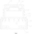
- the example anti-heating pull-out bottle cap mainly consists of a fixing assembly used to secure it to the bottle neck 7, an upper cover assembly placed on the fixing assembly, and an anti-counterfeiting structure positioned between the fixing assembly and the upper cover assembly.
- the fixing assembly includes an inner body 1, a fixing sleeve 3, an inner plug 2, a sealing bead 8, and an outer body 4.
- the main body 1 is overall cylindrical in shape, comprising a pouring spout segment 12 and a mounting segment 11 connected from top to bottom.
- the outer peripheral surface of the pouring spout segment 12 is equipped with external threads 121 for connection with the upper cover assembly.
- a stopper section 14 is centrally located within the pouring spout segment 12, with a gap between the stopper section 14 and the inner wall of the pouring spout segment 12.
- the stopper section 14 is connected to the pouring spout segment 12 via several connecting ribs 15.
- Several pouring channels 16 are formed between the stopper section 14, pouring spout segment 12, and the connecting ribs 15.
- the mounting segment 11 is designed to cooperate with the fixing sleeve 3 to securely fix the entire fixing assembly onto the bottle neck 7 in a non-detachable manner.
- the inner diameter of the mounting segment 11 is greater than that of the pouring spout segment 12, with a step portion 13 provided between the mounting segment 11 and the pouring spout segment 12.
- the inner plug 2 comprises an inner plug body 21 and a flanged portion 22.
- the inner plug body 21 is cylindrical and includes an upper inner plug segment 211 and a lower inner plug segment 212 connected from top to bottom.
- the upper inner plug segment 211 inserts into the pouring spout segment 12 and seals tightly against the inner wall of the pouring spout segment 12.
- the lower inner plug segment 212 can be inserted into the bottle neck 7 and seals tightly against the inner wall of the bottle neck 7.
- the bottom of the lower inner plug segment 212 is equipped with a pouring hole 213 for the liquid to flow through. To facilitate insertion into the bottle neck 7, the lower end of the lower inner plug segment 212 is tapered.
- the inner diameter of the upper inner plug segment 211 is greater than that of the lower inner plug segment 212, creating a step between them.
- the flanged portion 22 extends radially outward from the outer wall of the inner plug body 21 and seals with the upper opening of the fixing sleeve 3.
- a sealing bead 8 is installed inside the inner plug 2.
- the fixing sleeve 3 is cylindrical in structure and is sleeved onto the mounting segment 11. Between the inner wall of the fixing sleeve 3 and the outer wall of the lower inner plug segment 212, there is a slot 37 for inserting the bottle neck 7.
- the upper inner wall of the fixing sleeve 3 is provided with a first anti-rotation protrusion 33 (or first anti-rotation recess) that cooperates with a first anti-rotation recess 74 (or first anti-rotation protrusion) on the bottle neck 7.
- the lower part of the fixing sleeve 3 is equipped with multiple engageable claws 31 arranged along the circumference.
- the claws 31 are in an open state, allowing the bottle neck 7 to be inserted into the slot 37 between the inner plug body 21 and the fixing sleeve 3.
- the inner body 1 moves downward relative to the fixing sleeve 3, and the lower end of the inner body 1 slides along the outer surface 312 of the claws 31, causing the claws 31 to contract and engage with the first protrusion 71.
- the fixing sleeve 3 prevents relative rotational movement between itself and the bottle neck 7 through the cooperation of the first anti-rotation recess 74 and the first anti-rotation protrusion 33, and prevents relative axial movement between the fixing sleeve 3 and the bottle neck 7 through the cooperation of the claws 31 and the first protrusion 71.
- This design enhances anti-removal functionality and improves the stability of the bottle cap during installation.
- the fixed sleeve 3 and the inner plug 2 are of a split-type structure, with the fixed sleeve 3 made of hard plastic material. Between the fixed sleeve 3 and the mounting segment 11, there are anti-rotation structures to prevent relative rotational movement and axial limit structures to prevent relative axial movement. Because the fixed sleeve 3 is made of hard plastic material (such as ABS plastic), when heating the bottle cap with a hair dryer or hot water, the fixed sleeve 3 is not easily deformed. This prevents the fixed sleeve 3 from being pulled out from the bottleneck 7 using heating means alone, ensuring that the bottle cap can only be removed by destroying it.
- hard plastic material such as ABS plastic
- the fixed sleeve 3 and the inner plug 2 can be designed as a monolithic structure.
- the outer wall of the fixed sleeve 3 is provided with several second anti-rotation concave portions 36 (or second anti-rotation convex portions), while the inner wall of the mounting segment 11 is equipped with third anti-rotation convex portions 111 (or third anti-rotation concave portions) that cooperate with the second anti-rotation concave portions 36 (or convex portions).
- the interaction between the second anti-rotation concave portions 36 and the third anti-rotation convex portions 111 prevents relative rotational movement between the fixed sleeve 3 and the inner main body 1. This structure further enhances the stability and anti-pull-out performance of the bottle cap.
- the inner wall of installation section 11 is equipped with several circumferentially spaced limiting grooves 112. After crimping, at least one lower outer edge of claw 31 engages into at least one of the limiting grooves 112, thereby preventing relative axial movement between fixed sleeve 3 and inner body 1.
- This design allows claw 31 to simultaneously serve as an axial limit, which simplifies the structure.
- the limiting grooves 112 extend longitudinally along the circumferential direction as strip shapes, with a length greater than that of claw 31 along the circumferential direction. This configuration ensures that there is no directional requirement during the assembly of fixed sleeve 3, facilitating the assembly process. Such a design simplifies the installation procedure and enhances production efficiency.
- the lower end of flanging section 22 is equipped with a sealing portion 221 that matches the upper opening of fixed sleeve 3. After crimping, the sealing portion 221 is inserted into the upper opening of fixed sleeve 3. This design ensures a good seal of the bottle cap when closed, preserving the freshness of the beverage inside the bottle.
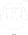
- the lower part of fixed sleeve 3 is equipped with several slots 32 arranged at intervals along the circumference and extending axially to the lower end face of fixed sleeve 3, thereby forming the claws 31.
- the longitudinal cross-section of claws 31 resembles a nearly right-angled triangle, comprising inner surface 311, outer surface 312, and end face 313.
- the outer surfaces 312 of multiple claws 31 are located on the same conical surface, while the inner surface 311 runs parallel to the axial direction of fixed sleeve 3, and the end face 313 is perpendicular to the axial direction of fixed sleeve 3. This structure of claws 31 enhances anti-pull performance, ensuring a safer and more reliable bottle cap.
- the inner and outer diameters of the upper part of fixed sleeve 3 gradually decrease from bottom to top.
- the radial height of the first anti-rotation convex portion 33 decreases gradually from bottom to top, while the radial height of the second anti-rotation concave portion 36 increases gradually from bottom to top.
- the upper part of fixed sleeve 3 is structured in this manner to accommodate the structure of the bottle neck on one hand, and to leave space for the third anti-rotation convex portion 111 on the inner body 1 on the other hand.
- protrusions 314 are provided on the inner surface 311 of the claw 31 to increase the bonding strength between the claw 31 and the first convex platform 71. This design enhances the secure attachment of the claw 31 to the first convex platform 71, thereby further improving anti-pull performance.
- the outer body 4 is cylindrical in shape and is fitted onto the mounting section 11 of the inner body 1. Between the outer body 4 and the mounting section 11, there are anti-rotation structures to prevent relative rotational movement and axial limiting structures to prevent relative axial movement.
- the outer body 4 serves both decorative purposes and secures the mounting section 11 of the inner body 1, preventing deformation during heating of the mounting section 11, which could otherwise cause the claws 31 to open and compromise the fixation structure.
- the inner wall of the outer body 4 is equipped with a first latch 411, which engages with the lower end face of the inner body 1 to prevent axial upward movement of the outer body 4 relative to the inner body 1.
- a first latch 411 engages with the lower end face of the inner body 1 to prevent axial upward movement of the outer body 4 relative to the inner body 1.
- the inner wall of the outer body 4 is provided with anti-pull tabs 422, which cooperate with the second protrusion 72 on the outer peripheral surface of the bottleneck 7 to prevent relative movement of the outer body 4 with respect to the bottleneck 7, thereby further increasing the bonding strength between the fixing component and the bottleneck 7.
- the outer body 4 comprises an outer body main body 41 and an anti-pull member 42 disposed on the inner wall at the lower end of the outer body main body 41.
- a plurality of anti-pull tabs 422 arranged along the circumferential direction are provided on the anti-pull member 42, which is made of hard plastic material.
- the anti-pull member 42 comprises a annular main body portion 421, and the anti-pull tabs 422 extend upwardly inward from the lower end of the main body portion 421 at an inward slant, forming an inverted structure.
- the anti-pull tabs 422 are not easily detached from the second protrusion 72.
- the anti-pull member 42 further includes at least two positioning parts 423 arranged at intervals along the circumferential direction on the inner wall of the main body portion 421. These at least two positioning parts 423 cooperate with the outer peripheral surface of steps on the bottleneck 7. During assembly of the bottle cap, the positioning parts 423 ensure concentricity with the outer peripheral surface of the second protrusion 72, preventing misalignment of the bottle cap.
- the lower end inner wall of the outer body 4 is provided with a mounting groove 412, and the main body portion 421 is engaged in the mounting groove 412.
- the inner diameter of the main body portion 421 is smaller than the outer diameter of the lower end of the fixing sleeve 3, thus allowing the main body portion 421 to serve as a limiting stop to prevent the fixing sleeve 3 from slipping off.
- the prevention structure includes several second protrusions 413 on the inner wall of the outer body 4 and several first protrusions 17 on the outer surface of the inner body 1, with each second protrusion 413 fitting between adjacent pairs of first protrusions 17.
- the inner wall of the outer body 4 above several second protrusions 413 has inwardly extending ridges 414 that cooperate with the second protrusions 413 to prevent axial downward movement of the outer body 4 relative to the inner body 1.
- the upper cover assembly includes an outer cover 6 and an inner cover 5 fixedly embedded within the outer cover 6.
- the inner wall of the inner cover 5 is provided with internal threads 51 that cooperate with external threads 121 on the inner body 1.
- the outer wall of the inner cover 5 is equipped with a groove 52, while the inner wall of the outer cover 6 is equipped with a protrusion 61 that engages with the groove 52, securely connecting the inner cover 5 and the outer cover 6.
- the positions of the protrusion 61 and the groove 52 can be swapped, meaning the protrusion 61 is placed on the inner cover 5 and the groove 52 is located on the outer cover 6.
- the inner cover 5 comprises a cylindrical body 53 with a lower end opening and an upper end opening, and a top portion 54 connected to the upper end opening of the cylindrical body 53.
- the cylindrical body 53 is made of rigid plastic material
- the top portion 54 is made of soft plastic material. This design utilizes rigid plastic for the portion of the inner cover 5 where the groove 52 is located, and soft plastic for the portion that interfaces with the end face of the liquid outlet section. This configuration enhances the sealing performance of the inner cover 5 while increasing its connection strength with the outer cover 6.
- the portion of the inner cover 5 with the groove 52 is less prone to deformation, preventing the outer cover 6 from being pulled out from the inner cover 5 by heating means alone. Only deformation of the outer cover 6 would separate the protrusion 61 from the groove 52, ensuring that the bottle cap can only be removed by damaging it, thereby achieving a one-time use of the cap and preventing its reuse, enhancing anti-counterfeiting measures effectively.
- the upper end surface of the cylindrical body 53 tightly adheres to the lower surface of the top portion 54, thereby preventing leakage between the upper end surface of the cylindrical body 53 and the lower surface of the top portion 54.
- the connection between the cylindrical body 53 and the outer cover 6 is achieved through the engagement of protrusion 61 on the outer cover 6 into the groove 52. This engagement ensures that the lower surface of the top portion 54 adheres closely to the upper end surface of the cylindrical body 53.
- the upper end of the cylindrical body 53 and the top portion 54 are integrally molded using a two-shot injection molding process. This integration allows the cylindrical body 53 and the top portion 54 to form a single part, facilitating assembly.
- the cylindrical body 53 is made of ABS plastic, while the top portion 54 is made of PE (polyethylene) plastic.
- the lower surface of the top 54 has a downward-extending sealing ring 55, which is made of soft plastic.
- This sealing ring 55 is designed to come into close contact with a dispensing port when the bottle cap is fully tightened, providing effective sealing to prevent liquid leakage.
- the anti-counterfeiting structure comprises a first anti-counterfeiting ring 91 on the outer cap 6 and a second anti-counterfeiting ring 92 on the outer body 4.
- the first anti-counterfeiting ring 91 has downward-extending first anti-counterfeiting teeth (not shown in the figure), and the second anti-counterfeiting ring 92 has upward-extending second anti-counterfeiting teeth (not shown in the figure).
- rotating the outer cap 6 causes the first anti-counterfeiting teeth to rotate.
- the first and/or second anti-counterfeiting teeth are designed to break upon rotation, and cannot be repaired once broken or twisted, thereby achieving anti-counterfeiting purposes.
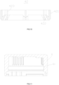
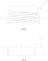
- a bottle body for use with the above-mentioned anti-heating extraction bottle cap, as shown in Figure 14 .
- the bottle body includes a bottle body (not shown in the figure) and a bottle neck 7 set on the bottle body, which has a bottle mouth 76.
- the outer wall of the bottle neck 7 is equipped with first protrusions 71 and second protrusions 72 arranged at intervals from top to bottom.
- the first locking recesses 74 are wider at the top and narrower at the bottom to facilitate smooth insertion and automatic alignment of the first locking protrusion 33 into the first locking recess 74 during sealing.
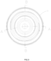
- Figure 16 shows the assembly diagram of the anti-heating extraction bottle cap with bottle neck 7, referring to Figures 1 and 16 .
- the lower end of installation section 11 of inner body 1 is positioned above claw 31, which remains in an open state.
- bottle neck 7 can be inserted into slot 37 between inner plug body 21 and fixing sleeve 3.
- the first locking protrusion 33 on fixing sleeve 3 inserts into the first locking recess 74 on the outer wall of bottle neck 7.
- downward pressure is applied to the anti-heating extraction bottle cap.
- Inner body 1 moves downward relative to fixing sleeve 3, and the lower end of inner body 1 slides along the outer side 312 of claw 31, causing claw 31 to contract and grip the first protrusion 71 of bottle neck 7.
- anti-pull buckle 422 locks onto the second protrusion 72, thus securely fixing the anti-heating extraction bottle cap onto bottle neck 7.
- the anti-heating extraction bottle cap of the present disclosure utilizes a fixed assembly with retractable claws 31 on fixing sleeve 3 and first protrusions 71 on bottle neck 7 through an expansion structure design, creating an inverted buckle inside the bottle to firmly integrate inner plug 2 and inner body 1 with the bottle. Even when heated and softened, they cannot be separated. Additionally, anti-pull buckle 422 on outer body 4 engages with second protrusion 72 on bottle neck 7, further enhancing the bonding strength between the fixed assembly and bottle neck 7.
Landscapes
- Engineering & Computer Science (AREA)
- Mechanical Engineering (AREA)
- Ceramic Engineering (AREA)
- Closures For Containers (AREA)
- Containers Having Bodies Formed In One Piece (AREA)
Applications Claiming Priority (3)
| Application Number | Priority Date | Filing Date | Title |
|---|---|---|---|
| CN202211296562.6A CN115626375A (zh) | 2022-10-21 | 2022-10-21 | 防二次使用的防伪瓶盖及其装配方法 |
| CN202321034009.5U CN220448372U (zh) | 2022-10-21 | 2023-04-28 | 防加热拔出瓶盖的内主体与瓶颈的固定结构 |
| PCT/CN2024/081586 WO2024222284A1 (zh) | 2022-10-21 | 2024-03-14 | 防加热拔出瓶盖及其内主体与瓶颈的固定结构 |
Publications (2)
| Publication Number | Publication Date |
|---|---|
| EP4516686A1 true EP4516686A1 (de) | 2025-03-05 |
| EP4516686A4 EP4516686A4 (de) | 2026-05-20 |
Family
ID=84906146
Family Applications (1)
| Application Number | Title | Priority Date | Filing Date |
|---|---|---|---|
| EP24795667.5A Pending EP4516686A4 (de) | 2022-10-21 | 2024-03-14 | Heiz-heraufzug verhindernder flaschenverschluss und befestigungsstruktur für den inneren hauptkörper eines flaschenverschlusses und flaschenhals |
Country Status (4)
| Country | Link |
|---|---|
| EP (1) | EP4516686A4 (de) |
| JP (1) | JP7819365B2 (de) |
| CN (9) | CN115626375A (de) |
| WO (1) | WO2024222284A1 (de) |
Families Citing this family (2)
| Publication number | Priority date | Publication date | Assignee | Title |
|---|---|---|---|---|
| CN115626375A (zh) * | 2022-10-21 | 2023-01-20 | 珠海经济特区龙狮瓶盖有限公司 | 防二次使用的防伪瓶盖及其装配方法 |
| CN117163471A (zh) * | 2023-09-01 | 2023-12-05 | 贵州百世佳包装股份有限公司 | 一种二次防伪瓶盖 |
Family Cites Families (10)
| Publication number | Priority date | Publication date | Assignee | Title |
|---|---|---|---|---|
| US6793101B2 (en) * | 2000-12-21 | 2004-09-21 | Yoshino Kogyosho Co., Ltd. | Synthetic resin bottle cap unit |
| CN2501830Y (zh) * | 2001-05-18 | 2002-07-24 | 李达 | 一次性使用的防伪瓶盖 |
| CN2505427Y (zh) * | 2001-09-30 | 2002-08-14 | 欧阳宣 | 防伪瓶盖 |
| CN2848733Y (zh) * | 2005-09-02 | 2006-12-20 | 潍坊齐韵陶瓷有限公司 | 一种防伪酒瓶 |
| CN113353442B (zh) * | 2021-06-22 | 2024-11-19 | 成都天坤盖业有限公司 | 一种酱酒通用防伪瓶盖 |
| CN115057106B (zh) * | 2022-07-18 | 2025-01-17 | 海普智联科技股份有限公司 | 防伪瓶盖以及防伪酒瓶 |
| CN115626375A (zh) * | 2022-10-21 | 2023-01-20 | 珠海经济特区龙狮瓶盖有限公司 | 防二次使用的防伪瓶盖及其装配方法 |
| CN218432689U (zh) | 2022-10-21 | 2023-02-03 | 珠海经济特区龙狮瓶盖有限公司 | 防伪瓶盖与瓶颈的固定结构 |
| CN218705319U (zh) | 2022-10-21 | 2023-03-24 | 珠海经济特区龙狮瓶盖有限公司 | 酒瓶瓶体及酒瓶 |
| CN218432690U (zh) | 2022-10-21 | 2023-02-03 | 珠海经济特区龙狮瓶盖有限公司 | 防二次使用的防伪瓶盖 |
-
2022
- 2022-10-21 CN CN202211296562.6A patent/CN115626375A/zh active Pending
-
2023
- 2023-04-28 CN CN202510957628.9A patent/CN121020011A/zh active Pending
- 2023-04-28 CN CN202310485653.2A patent/CN116620707B/zh active Active
- 2023-04-28 CN CN202321030415.4U patent/CN220130808U/zh active Active
- 2023-04-28 CN CN202510957570.8A patent/CN120717063A/zh active Pending
- 2023-04-28 CN CN202321029828.0U patent/CN220501446U/zh active Active
- 2023-04-28 CN CN202510957685.7A patent/CN120817327A/zh active Pending
- 2023-04-28 CN CN202321034009.5U patent/CN220448372U/zh active Active
- 2023-04-28 CN CN202321034050.2U patent/CN219905054U/zh active Active
-
2024
- 2024-03-14 WO PCT/CN2024/081586 patent/WO2024222284A1/zh not_active Ceased
- 2024-03-14 EP EP24795667.5A patent/EP4516686A4/de active Pending
- 2024-03-14 JP JP2024563666A patent/JP7819365B2/ja active Active
Also Published As
| Publication number | Publication date |
|---|---|
| CN120817327A (zh) | 2025-10-21 |
| JP2025517286A (ja) | 2025-06-05 |
| JP7819365B2 (ja) | 2026-02-24 |
| CN220448372U (zh) | 2024-02-06 |
| EP4516686A4 (de) | 2026-05-20 |
| CN220130808U (zh) | 2023-12-05 |
| CN120717063A (zh) | 2025-09-30 |
| CN116620707B (zh) | 2025-07-29 |
| CN115626375A (zh) | 2023-01-20 |
| CN219905054U (zh) | 2023-10-27 |
| WO2024222284A1 (zh) | 2024-10-31 |
| CN121020011A (zh) | 2025-11-28 |
| CN220501446U (zh) | 2024-02-20 |
| CN116620707A (zh) | 2023-08-22 |
Similar Documents
| Publication | Publication Date | Title |
|---|---|---|
| RU2388672C2 (ru) | Контейнер для напитков | |
| US6491175B1 (en) | Single piece closure for a pressurized container | |
| EP3661856B1 (de) | Verschluss | |
| CA2307851C (en) | Snap-on screw-off closure | |
| US6595395B2 (en) | Dispenser having a fixing member, and a fixing member for such a dispenser | |
| US5875906A (en) | Tamper evident sleeves and method of forming them | |
| US6793082B1 (en) | Snap-on screw-off closure for use in combination with a container | |
| US7210593B2 (en) | Tamper-evident quick twist closure | |
| US6325227B1 (en) | Tamper-indicating closure with horizontal undercuts | |
| JP2000355353A (ja) | 排液特徴部を備えた不正支持閉鎖体 | |
| JP7819365B2 (ja) | 加熱抜去防止キャップ、及びそのインナー本体とボトルネックとの固定構造 | |
| HUP0203602A2 (hu) | Palacktartállyal együttműködő zárósapka | |
| US6152315A (en) | Closure having back-angled lugs | |
| US6343705B1 (en) | Closure having back-angled lugs | |
| WO1999003747A1 (en) | Push-on closure | |
| CN218432690U (zh) | 防二次使用的防伪瓶盖 | |
| CN218705319U (zh) | 酒瓶瓶体及酒瓶 | |
| CN218432689U (zh) | 防伪瓶盖与瓶颈的固定结构 | |
| CN114072240B (zh) | 流体制品的分配器 | |
| JP7169716B2 (ja) | 封緘部付きキャップ | |
| CN218432688U (zh) | 防伪瓶盖与瓶颈的止转结构 | |
| JP7469071B2 (ja) | 瓶口用キャップ | |
| JPH04115147U (ja) | 密閉キヤツプ | |
| MXPA00000563A (en) | Closure with extended seal member | |
| MXPA00000562A (es) | Tapa que se coloca a presion |
Legal Events
| Date | Code | Title | Description |
|---|---|---|---|
| STAA | Information on the status of an ep patent application or granted ep patent |
Free format text: STATUS: THE INTERNATIONAL PUBLICATION HAS BEEN MADE |
|
| PUAI | Public reference made under article 153(3) epc to a published international application that has entered the european phase |
Free format text: ORIGINAL CODE: 0009012 |
|
| STAA | Information on the status of an ep patent application or granted ep patent |
Free format text: STATUS: REQUEST FOR EXAMINATION WAS MADE |
|
| 17P | Request for examination filed |
Effective date: 20241129 |
|
| AK | Designated contracting states |
Kind code of ref document: A1 Designated state(s): AL AT BE BG CH CY CZ DE DK EE ES FI FR GB GR HR HU IE IS IT LI LT LU LV MC ME MK MT NL NO PL PT RO RS SE SI SK SM TR |