EP4516677A1 - Anordnung für ein luftfahrzeug mit einem flügel und einem strahltriebwerk-pylon zur kopplung eines antriebssystems an den flügel - Google Patents
Anordnung für ein luftfahrzeug mit einem flügel und einem strahltriebwerk-pylon zur kopplung eines antriebssystems an den flügel Download PDFInfo
- Publication number
- EP4516677A1 EP4516677A1 EP24196886.6A EP24196886A EP4516677A1 EP 4516677 A1 EP4516677 A1 EP 4516677A1 EP 24196886 A EP24196886 A EP 24196886A EP 4516677 A1 EP4516677 A1 EP 4516677A1
- Authority
- EP
- European Patent Office
- Prior art keywords
- starboard
- port
- fixed
- fitting
- assembly
- Prior art date
- Legal status (The legal status is an assumption and is not a legal conclusion. Google has not performed a legal analysis and makes no representation as to the accuracy of the status listed.)
- Pending
Links
Images
Classifications
-
- B—PERFORMING OPERATIONS; TRANSPORTING
- B64—AIRCRAFT; AVIATION; COSMONAUTICS
- B64D—EQUIPMENT FOR FITTING IN OR TO AIRCRAFT; FLIGHT SUITS; PARACHUTES; ARRANGEMENT OR MOUNTING OF POWER PLANTS OR PROPULSION TRANSMISSIONS IN AIRCRAFT
- B64D27/00—Arrangement or mounting of power plants in aircraft; Aircraft characterised by the type or position of power plants
- B64D27/40—Arrangements for mounting power plants in aircraft
- B64D27/404—Suspension arrangements specially adapted for supporting vertical loads
-
- B—PERFORMING OPERATIONS; TRANSPORTING
- B64—AIRCRAFT; AVIATION; COSMONAUTICS
- B64D—EQUIPMENT FOR FITTING IN OR TO AIRCRAFT; FLIGHT SUITS; PARACHUTES; ARRANGEMENT OR MOUNTING OF POWER PLANTS OR PROPULSION TRANSMISSIONS IN AIRCRAFT
- B64D27/00—Arrangement or mounting of power plants in aircraft; Aircraft characterised by the type or position of power plants
- B64D27/02—Aircraft characterised by the type or position of power plants
- B64D27/10—Aircraft characterised by the type or position of power plants of gas-turbine type
- B64D27/12—Aircraft characterised by the type or position of power plants of gas-turbine type within, or attached to, wings
-
- B—PERFORMING OPERATIONS; TRANSPORTING
- B64—AIRCRAFT; AVIATION; COSMONAUTICS
- B64D—EQUIPMENT FOR FITTING IN OR TO AIRCRAFT; FLIGHT SUITS; PARACHUTES; ARRANGEMENT OR MOUNTING OF POWER PLANTS OR PROPULSION TRANSMISSIONS IN AIRCRAFT
- B64D27/00—Arrangement or mounting of power plants in aircraft; Aircraft characterised by the type or position of power plants
- B64D27/02—Aircraft characterised by the type or position of power plants
- B64D27/16—Aircraft characterised by the type or position of power plants of jet type
- B64D27/18—Aircraft characterised by the type or position of power plants of jet type within, or attached to, wings
-
- B—PERFORMING OPERATIONS; TRANSPORTING
- B64—AIRCRAFT; AVIATION; COSMONAUTICS
- B64D—EQUIPMENT FOR FITTING IN OR TO AIRCRAFT; FLIGHT SUITS; PARACHUTES; ARRANGEMENT OR MOUNTING OF POWER PLANTS OR PROPULSION TRANSMISSIONS IN AIRCRAFT
- B64D27/00—Arrangement or mounting of power plants in aircraft; Aircraft characterised by the type or position of power plants
- B64D27/40—Arrangements for mounting power plants in aircraft
- B64D27/402—Arrangements for mounting power plants in aircraft comprising box like supporting frames, e.g. pylons or arrangements for embracing the power plant
Definitions
- the present invention relates to an assembly for an aircraft comprising a wing and a power plant for coupling a propulsion system to the wing, as well as to an aircraft comprising a propulsion system and such an assembly for coupling the propulsion system to the wing.
- a propulsion system typically includes, for example, a turbojet engine that is attached to a wing of the aircraft using a jet engine pylon.
- the jet engine pylon is typically made up of a primary structure formed by a box consisting of an upper spar, a lower spar, and two side panels connecting the two spars, and internal ribs distributed along the box.
- the turbojet engine is fixed under the engine pylon by means of engine mounts which conventionally comprise, at the front, a front engine mount, at the rear, a rear engine mount, and between the front and rear engine mounts, a thrust force recovery assembly comprising recovery rods fixed between the turbojet engine and the primary structure of the pylon, to absorb the thrust forces generated by the turbojet engine.
- engine mounts which conventionally comprise, at the front, a front engine mount, at the rear, a rear engine mount, and between the front and rear engine mounts, a thrust force recovery assembly comprising recovery rods fixed between the turbojet engine and the primary structure of the pylon, to absorb the thrust forces generated by the turbojet engine.
- the engine pylon is further secured to the wing structure by means of fittings through which the forces from the turbojet are transferred to the wing structure.
- An object of the present invention is to provide an assembly for an aircraft comprising a wing and a reactor mast for coupling a propulsion system to the wing and which comprises means of attachment to the wing which ensure an improved transfer of forces to the structure of the wing while making it possible to guarantee the transmission of these forces in the event of breakage of a fixing element.
- a rear portion of said primary structure comprises a first fixing yoke extending at the rear and at the level of the vertical median plane, said first fixing yoke being fixed to said first fitting by a seventh connection having at least one degree of freedom in rotation about an axis extending generally parallel to the median plane.
- the rear part also includes a starboard fixing clevis and a port fixing clevis extending on either side and aft of said rear part.
- each shackle comprises two plates joined together and fixed against each other.
- said starboard and port fittings have a generally T-shaped section with a horizontal part fixed to the lower part of said front spar and a vertical part in which the associated pivot connections are made.
- each starboard and port fitting is made up of two elements having a generally ⁇ -shaped section and being integral with one another.
- said first fixing yoke comprises two sub-yokes joined together and fixed against each other.
- the seventh connection between said first fixing yoke and said first fitting comprises a main axis and a secondary axis extending coaxially and inside said main axis.
- said rear part comprises a first port outgrowth and a first starboard outgrowth extending vertically in a plane generally perpendicular to the vertical median plane, said first outgrowths being arranged on either side of said primary structure.
- the assembly comprises a first connecting rod, a first end of which is fixed to said first outgrowth by an eighth pivot connection.
- the assembly comprises a second connecting rod, a first end of which is fixed to said first starboard outgrowth by a ninth pivot connection.
- Said port and starboard fittings respectively comprise a second port protrusion and a second starboard protrusion extending vertically in a plane generally perpendicular to the vertical median plane.
- Said second protrusions extend in the lower part of the fittings, the second starboard protrusion being fixed to a second end of said first connecting rod by a tenth pivot connection and said second port protrusion being fixed to a second end of said second connecting rod by an eleventh pivot connection.
- said eighth and ninth pivot links have an adjusted connection axis and at least one of said tenth and eleventh pivot links has play.
- the invention also provides an aircraft comprising a propulsion system and an assembly as described above, where the propulsion system is attached to the engine pylon.
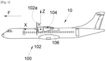
- FIG. 1 shows an aircraft 10 which comprises a propulsion system 102, for example of the turbojet or turboprop type.
- the propulsion system 102 is linked to a wing 104 of the aircraft 10 by means of a reactor mast 106.
- the wing 104 and the reactor mast 106 form an assembly 100 according to the invention and the propulsion system 102 is fixed to the reactor mast 106 by any suitable fixing means known to those skilled in the art such as those disclosed in the document US-A-2016/0221682 .
- X the longitudinal direction of the propulsion system which is horizontal when the aircraft is on the ground
- Y the transverse direction which is horizontal when the aircraft is on the ground
- Z the vertical direction which is vertical when the aircraft is on the ground
- the reactor mast 106 and the propulsion system 102 have a vertical median plane XZ and the propulsion system 102 is here a turboprop with a propeller 102a, but it could be of the double-flow turbojet type with a nacelle.
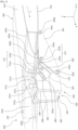
- the reactor mast 106 comprises a rigid structure forming a box and also called primary structure 202.
- the primary structure 202 illustrated here in section along a plane parallel to the ZY plane, is conventionally formed of an upper spar 204, a lower spar 206 and two starboard and port side panels connecting the two spars 204 and 206.
- the shape of the primary structure 202 is in this example configured so that the reactor mast 106 has a substantially rectangular rear portion 203, located at the rear end of the reactor mast 106 in the direction of advancement F.
- the structure of the wing 104 comprises a front spar 210, an extrados panel 214 and a lower surface panel 216 which are both fixed to the front spar 210 and extend generally in horizontal planes XY.
- its structure comprises other elements (not illustrated) such as ribs which are distributed between the extrados panel 214 and the lower surface panel 216.
- the front spar 210 here takes the form of a profile in the shape of an inverted Z step on the Figs. 2 And 3 , with an upper wing 210a (also called a top portion) and a lower wing 210b (also called a bottom portion) that are generally horizontal and a central portion 210c generally perpendicular to the median plane and extending generally vertically parallel to the YZ plane.
- the extrados panel 214 is attached above the upper wing 210a of the spar 210 and the intrados panel 216 is attached below the lower wing 210b of the spar 210.
- the attachment of the front spar 210 to the panels 214 and 216 is achieved by any suitable means such as welds, bolts, etc.
- the extrados panel 214 is thus fixed in the upper part of the front spar 210 and the intrados panel 216 is fixed in the lower part of the front spar 210.
- the central part 210c is at the level of the leading edge of the wing 104.
- the front spar 210 carries a first fitting 211a, called the central fitting, fixed at the level of the vertical median plane XZ and more particularly here at the central part 210c of the front spar 210.
- the intrados panel 216 carries a starboard fitting 212 and a port fitting 213 which are fixed to the external face of the intrados panel 216.
- the starboard 212 and port 213 fittings are fixed at the level, that is to say generally in vertical alignment, of the lower part 210b of the front spar 210.
- the assembly 100 comprises a first starboard shackle 282 fixed to the starboard fitting 212 by a first 292a and a second 292c pivot links whose axis of rotation is generally horizontal. More precisely, the axes of the links 292a and 292c extend generally perpendicular to the median plane XZ.
- the assembly also includes a first port shackle 283 fixed to the port fitting 213 by a fourth 293a and a fifth 293c pivot links around an axis whose axis of rotation is generally horizontal. More precisely, the axes of the links 293a and 293c extend generally perpendicular to the median plane (XZ).
- the rear portion 203 of the primary structure 202 comprises a first fixing yoke 211b which extends to the rear and at the level of the vertical median plane XZ. More precisely, the first fixing yoke 211b extends at the top of the rear portion 203 and is located opposite the first fitting 211a.
- the first fixing yoke 211b is fixed to the first fitting 211a by a seventh connection 211c having at least one degree of freedom in rotation about a vertical axis extending parallel to the vertical axis Z.
- the seventh connection 211c may be in the form of a pivot connection or a pivot-sliding connection.
- the first fitting 211a takes the form of a female yoke and the first fixing yoke 211b takes the form of a male yoke inserted into the female yoke.
- This attachment point between the engine mast 106 and the wing 104 makes it possible to absorb the axial forces along the X axis and the lateral forces along the Y axis. This attachment point also makes it possible to absorb the moment around the Y axis.
- the rear portion 203 also includes a starboard fixing yoke 272 and a port fixing yoke 273 which extend to the rear of the rear portion 203. More particularly here, the starboard fixing yoke 272 and port fixing yoke 273 extend in the lower part and on either side of said rear portion 203.
- the starboard attachment yoke 272 is attached by a third pivot link 292e to the starboard shackle 282 about a generally horizontal axis and the port attachment yoke 273 is attached by a sixth pivot link 293e to the port shackle 283 about a horizontal axis.
- the axes of the third and sixth pivot links 292e and 293e extend generally perpendicular to the median plane XZ, i.e. generally parallel to the transverse axis Y.
- the axes of the links 292e and 293e may further extend generally coaxially.
- the two attachment points of the starboard 272 and port 273 attachment clevises located on either side of the lower spar 206 of the primary structure 202 are connected to the starboard 212 and port 213 fittings secured to the wing 104 by two first starboard 282 and port 283 shackles having three attachment points (namely the associated pivot connections described above).
- these different attachment points of the engine pylon 106 to the wing 104 make it possible to ensure the transfer of vertical forces (along the Z axis) and axial forces (along the X axis).
- These fixing points also make it possible to take up the moments around the X and Z axes.
- This particular implementation also makes it possible to precisely determine the paths taken by the forces through the engine mast 106 to the wing 104.
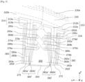
- the first starboard 282 and port 283 shackles, the starboard 282 and port 283 clevises and the starboard 212 and port 213 fittings each have a bore into which a pin is threaded so as to form the pivot connections 292a, 292c, 292e and 293a, 293c, 293e.
- the first starboard shackle 282 and the first port shackle 283 have a generally triangular shape.
- the first 292a and second 292c pivot links are disposed respectively in a first 292b and a second 292d corner.
- top of the first starboard shackle and the third pivot link 292e is disposed in a third bottom corner 292f of the first starboard shackle 282.
- the fourth 293a and fifth 293c pivot links are disposed respectively in a fourth 293b and a fifth 293d top corners of the first port shackle 213 and the sixth pivot link 293e is disposed in a sixth bottom corner 293f of the first port shackle 283.
- triangular shackles makes it possible in particular to make the assembly 100 compatible with the use of an aerodynamically shaped fairing at least partially covering the reactor mast 106.
- the assembly 100 comprises a second starboard shackle 282' which extends generally parallel to the first starboard shackle 282 and which is fixed to the starboard fitting 212 by the first 292a and second 292c connections and to the starboard fixing clevis by the third connection 292e.
- the assembly 100 comprises a second port shackle 283' which extends generally parallel to the first port shackle 283 and which is fixed to the port fitting 213 by the fourth 293a and fifth 293c connections and to the port fixing clevis 273 by said sixth connection 293e.
- first 282 and second 282' starboard shackles grip the starboard fitting 212 and the starboard fixing clevis 272 while the first 283 and second 283' port shackles grip the port fitting 213 and the port fixing clevis 273.
- each starboard 212 and port 213 fitting is connected respectively to the starboard fixing clevis 272 and to the port fixing clevis 273 by two shackles, respectively 282, 282' and 283, 283'.
- Doubling the starboard and port shackles makes it possible to multiply the paths taken by the forces passing from the propulsion system 102 to the wing 104. This also makes it possible to ensure continuity of the transfers of forces in the event of breakage of one of the shackles or of a point of attachment of these shackles at the level of the engine pylon 106 or the wing 104.
- first and second starboard shackles 282 and 282' are generally identical. The same is true for the first and second port shackles 283 and 283'. However, it is conceivable to provide different shapes for the first and second shackles.
- each shackle 282, 282', 283, 283' comprises two plates 282a, 282a', 282b, 282b', 283a, 283a', 283b, 283b' joined and fixed against each other.
- the first starboard shackle 282 comprises two plates 282a and 282b
- the second starboard shackle 282' comprises two plates 282a' and 282b'
- the first shackle port shackle 283 has two plates 283a and 283b
- the second port shackle 283' has two plates 283a' and 283b'.
- the plates of each shackle are identical.
- each shackle makes it possible to multiply the paths taken by the forces passing from the propulsion system 102 to the wing 104 and to ensure continuity of the transfers of forces in the event of breakage of one of the plates of each shackle or of a fixing point of these plates.
- the starboard 212 and port 213 fittings have a generally T-shaped section with a horizontal part fixed to the lower part 210b of the front spar 210 and a vertical part in which the associated pivot connections are made. More precisely, the vertical part of the starboard fitting 212 has two bores in which pins are threaded to respectively form the first 292a and the second 292b connections.
- the vertical part of the port fitting 213 has two bores into which pins are threaded to respectively form the fourth 293a and the fifth 293b connections.
- each starboard 212 and port 213 fitting is made up of two elements, respectively 212a, 212b and 213a, 213b, having a generally ⁇ -shaped section.
- the two elements of each fitting are secured to each other. More precisely, the two elements of each fitting are secured to each other by the vertical parts of the ⁇ which together form the vertical part of the T of the fitting, while the horizontal parts of these ⁇ -shaped elements are arranged opposite each other and together form the horizontal part of the T of the fitting.
- each fitting makes it possible to multiply the paths taken by the forces passing from the propulsion system 102 to the wing 104 and to ensure continuity of the transfers of forces in the event of breakage of one of the elements of each fitting.
- the first fixing yoke 211b comprises two sub-yokes 2111 and 2113 joined and fixed against each other.
- the two sub-yokes 2111 and 2113 are identical.
- the implementation of two sub-yokes 2111 and 2113 fixed to each other to form the first fixing yoke 221b makes it possible to multiply the paths taken by the forces passing from the propulsion system 102 to the wing 104 and to ensure continuity of the transfers of forces in the event of rupture of one of the sub-yokes of the first fixing yoke 211b.
- the seventh connection 211c between the first fixing yoke 211b and the first fitting 211a comprises a main axis (not shown) and a secondary axis (not shown) extending coaxially and inside the main axis.
- the main axis and the secondary axis extend parallel to the vertical axis Z.
- first fitting 211a and the first fixing yoke 211b each comprise a bore in which the main axis is threaded to form the seventh pivot connection 211c.
- the secondary axis is threaded into the main axis so as to ensure continuity of force transfers in the event of breakage of the main axis.
- the assembly 100 further comprises a set of two connecting rods 275a, 275b making it possible to react to the forces coming from the propulsion system 102 and which could generate an oscillatory movement on the reactor mast 106.
- the rear part 203 of the primary structure 202 comprises a first port outgrowth 274a and a first starboard outgrowth 274b.
- each first outgrowth 274a, 274b has an ear shape and extends vertically and perpendicularly to the side walls 208 of the primary structure 202, that is to say in a plane perpendicular to the vertical median plane XZ. More precisely, the first outgrowths 274a and 274b here extend generally to half the height of their respective side wall 208.
- the port 213 and starboard 212 fittings respectively carry a second port protrusion 274c and a second starboard protrusion 274d.
- each second protrusion 274c, 274d also has an ear shape and extends vertically in a plane perpendicular to the vertical median plane XZ.
- the second protrusions 274c, 274d extend on the vertical part of the T of each fitting.
- first protrusions 274a and 274b face each other.
- second protrusions 274c and 274d also face each other.
- the set of connecting rods 275a, 275b crosswise connects the fittings 212 and 213 to the rear part 203 of the primary structure 202. More precisely, a first connecting rod 275a connects the first port protrusion 274a to the second starboard protrusion 274d while the second connecting rod 275b connects the first starboard protrusion 274b to the second port protrusion 274c.
- the first 275a and second 275b connecting rods are therefore crossed and extend substantially in two parallel planes perpendicular to the vertical median plane XZ. The two parallel planes are slightly spaced to facilitate the crossing of the first 275a and second 275b connecting rods.
- first connecting rod 275a The ends of the first connecting rod 275a are secured to the first port outgrowth 274a and to the second starboard outgrowth 274d respectively by an eighth 284a and a ninth 284b pivot connections.
- the ends of the second connecting rod 275b are secured to the first starboard outgrowth 274b and to the second port outgrowth 274c respectively by a tenth 284c and an eleventh 284d pivot connections.
- the first connecting rod 275a is said to be “engaged” while the second connecting rod 275b is said to be “on standby”.
- the connecting axes of the eighth 284a and ninth 284b pivot connections are adjusted and therefore react to the forces under stress, so that the first connecting rod 275a represents the so-called "main" force path for the transmission of forces having a component substantially oriented in the transverse direction Y.
- At least one of the tenth 284c and eleventh 284d pivot connections has a clearance which allows, in the event of breakage of the first connecting rod 275a, to engage the second connecting rod 275b so that it is the second connecting rod 275b which reacts to the forces.
- the second connecting rod 275b thus represents the so-called “secondary” force path.
- the twelfth 284c and thirteenth 284d pivot connections each have a connecting pin carried respectively by the first starboard protrusion 274b and by the second port protrusion 274c.
- At least one of the bores provided at the ends of the second connecting rod 275b and cooperating with these connecting pins has, for example, an oblong shape such that the second connecting rod 275b is mounted with play at at least one of the tenth 284c and eleventh 284d pivot connections.
Landscapes
- Engineering & Computer Science (AREA)
- Aviation & Aerospace Engineering (AREA)
- Mutual Connection Of Rods And Tubes (AREA)
- Jib Cranes (AREA)
- Transmission Devices (AREA)
Applications Claiming Priority (1)
| Application Number | Priority Date | Filing Date | Title |
|---|---|---|---|
| FR2309132A FR3152495A1 (fr) | 2023-08-31 | 2023-08-31 | Ensemble pour un aéronef comportant une aile et un mât réacteur pour coupler un système de propulsion à ladite aile |
Publications (1)
| Publication Number | Publication Date |
|---|---|
| EP4516677A1 true EP4516677A1 (de) | 2025-03-05 |
Family
ID=88779287
Family Applications (1)
| Application Number | Title | Priority Date | Filing Date |
|---|---|---|---|
| EP24196886.6A Pending EP4516677A1 (de) | 2023-08-31 | 2024-08-28 | Anordnung für ein luftfahrzeug mit einem flügel und einem strahltriebwerk-pylon zur kopplung eines antriebssystems an den flügel |
Country Status (4)
| Country | Link |
|---|---|
| US (1) | US12522365B2 (de) |
| EP (1) | EP4516677A1 (de) |
| CN (1) | CN119527558A (de) |
| FR (1) | FR3152495A1 (de) |
Citations (4)
| Publication number | Priority date | Publication date | Assignee | Title |
|---|---|---|---|---|
| US4560122A (en) * | 1983-01-12 | 1985-12-24 | British Aerospace Public Limited Company | Power plant attachment arrangements for aircraft wings |
| US20160221682A1 (en) | 2015-01-30 | 2016-08-04 | Airbus Operations Sas | Propulsion assembly incorporating a turbojet and a mounting pylon enabling a new distribution of the forces between the turbojet and the wing |
| FR3044297A1 (fr) * | 2015-11-27 | 2017-06-02 | Airbus Operations Sas | Ensemble moteur pour aeronef comprenant des attaches moteur arriere sous forme de manilles |
| US20220194610A1 (en) * | 2019-05-10 | 2022-06-23 | Airbus Operations Limited | Aircraft assembly |
Family Cites Families (2)
| Publication number | Priority date | Publication date | Assignee | Title |
|---|---|---|---|---|
| FR3000529B1 (fr) * | 2012-12-28 | 2015-03-06 | Airbus Operations Sas | Dispositif de liaison souple pour ensemble propulsif d'aeronef |
| US10583930B2 (en) * | 2017-06-02 | 2020-03-10 | Spirit Aerosystems, Inc. | Aircraft engine attachment assembly |
-
2023
- 2023-08-31 FR FR2309132A patent/FR3152495A1/fr not_active Ceased
-
2024
- 2024-08-28 EP EP24196886.6A patent/EP4516677A1/de active Pending
- 2024-08-29 US US18/819,052 patent/US12522365B2/en active Active
- 2024-09-02 CN CN202411220625.9A patent/CN119527558A/zh active Pending
Patent Citations (4)
| Publication number | Priority date | Publication date | Assignee | Title |
|---|---|---|---|---|
| US4560122A (en) * | 1983-01-12 | 1985-12-24 | British Aerospace Public Limited Company | Power plant attachment arrangements for aircraft wings |
| US20160221682A1 (en) | 2015-01-30 | 2016-08-04 | Airbus Operations Sas | Propulsion assembly incorporating a turbojet and a mounting pylon enabling a new distribution of the forces between the turbojet and the wing |
| FR3044297A1 (fr) * | 2015-11-27 | 2017-06-02 | Airbus Operations Sas | Ensemble moteur pour aeronef comprenant des attaches moteur arriere sous forme de manilles |
| US20220194610A1 (en) * | 2019-05-10 | 2022-06-23 | Airbus Operations Limited | Aircraft assembly |
Also Published As
| Publication number | Publication date |
|---|---|
| FR3152495A1 (fr) | 2025-03-07 |
| US12522365B2 (en) | 2026-01-13 |
| US20250074610A1 (en) | 2025-03-06 |
| CN119527558A (zh) | 2025-02-28 |
Similar Documents
| Publication | Publication Date | Title |
|---|---|---|
| EP2170704B1 (de) | Vorrichtung zur kupplung eines luftfahrzeugtriebwerks und verfahren zur befestigung eines luftfahrzeugtriebwerks mittels solch einer vorrichtung | |
| EP2137072B1 (de) | Vorrichtung zur befestigung eines flugzeugtriebwerks und flugzeug mit mindestens einer derartigen vorrichtung | |
| EP3505439B1 (de) | Einheit für ein luftfahrzeug, die eine primärstruktur eines aufhängungsmasts umfasst, die an einem flügelkasten durch befestigungselemente befestigt ist und im vorderkantenbereich ein reduziertes volumen aufweist | |
| EP3505448B1 (de) | Einheit für ein luftfahrzeug, die eine primärstruktur eines aufhängungsmasts umfasst, die an einem flügelkasten mithilfe von anschlüssen reduzierten volumens in der vorderkantenzone befestigt ist | |
| FR3014840A1 (fr) | Ensemble pour aeronef comprenant un corps d'attache moteur equipe d'au moins une ferrure de support de manille penetrant dans le caisson du mat d'accrochage | |
| FR2887851A1 (fr) | Mat d'accrochage de moteur pour aeronef | |
| EP3521173B1 (de) | Einheit für luftfahrzeug, die eine primärstruktur einer aufhängesäule umfasst, die an einem fahrwerkskasten mithilfe einer verschraubten verbindung befestigt ist | |
| EP4368512B1 (de) | Anordnung für ein flugzeug mit einem flügel und einem reaktormast zur kopplung eines antriebssystems an den flügel | |
| FR3099464A1 (fr) | Mat reacteur pour coupler un turboreacteur a une aile d’un aeronef | |
| FR3065442A1 (fr) | Ensemble moteur pour aeronef comprenant une attache moteur avant integree au caisson du mat d'accrochage | |
| FR3073824A1 (fr) | Ensemble pour aeronef comprenant une structure primaire de mat d'accrochage fixee a un caisson de voilure par des attaches partiellement enterrees dans la structure primaire | |
| EP4484297B1 (de) | Vordermotorbefestigungssystem für einen flugzeugmotor mit kompakter struktur | |
| EP3939891B1 (de) | Anordnung für ein luftfahrzeug aus einem flügel und einem triebwerksträger zur ankopplung eines turbotriebwerks an diesen flügel | |
| EP3437999B1 (de) | Leichte primärstruktur für aufhängemast eines triebwerks eines luftfahrzeugs | |
| EP4491518B1 (de) | Flugzeugtriebwerkanordnung mit einer hauptstange zur motorbefestigung, sowie zwei parallel an einer querverstärkung vor einer primärstruktur eines masts | |
| FR2963608A1 (fr) | Adaptateur destine a etre interpose entre une structure rigide de mat d'accrochage de turbomoteur d'aeronef et un element de voilure | |
| EP4516677A1 (de) | Anordnung für ein luftfahrzeug mit einem flügel und einem strahltriebwerk-pylon zur kopplung eines antriebssystems an den flügel | |
| EP4183690B1 (de) | Triebwerksmast zur kopplung eines strahltriebwerks an einen flügel eines flugzeugs | |
| EP4467461B1 (de) | Anordnung für ein flugzeug mit einem flügel und einem triebwerkmast zur kopplung eines antriebssystems an den flügel | |
| EP4331974B1 (de) | Verbesserte verkleidung für einen flugzeugpylon, verkleidungsanordnung, flugzeugpylon und flugzeug | |
| EP4488178B1 (de) | Montage eines befestigungsmastes mit einem flugzeugmotor | |
| EP4442577B1 (de) | Reaktormast zur befestigung eines flugzeugmotors | |
| EP4711280A1 (de) | Antriebsanordnung mit einem in der höhe kompakten motorbefestigungselement, luftfahrzeug mit mindestens einer solchen antriebsanordnung | |
| EP4656513A1 (de) | Luftfahrzeug mit mindestens einem flügelbefestigungssystem, das mindestens eine seitenstange aufweist |
Legal Events
| Date | Code | Title | Description |
|---|---|---|---|
| PUAI | Public reference made under article 153(3) epc to a published international application that has entered the european phase |
Free format text: ORIGINAL CODE: 0009012 |
|
| STAA | Information on the status of an ep patent application or granted ep patent |
Free format text: STATUS: THE APPLICATION HAS BEEN PUBLISHED |
|
| AK | Designated contracting states |
Kind code of ref document: A1 Designated state(s): AL AT BE BG CH CY CZ DE DK EE ES FI FR GB GR HR HU IE IS IT LI LT LU LV MC ME MK MT NL NO PL PT RO RS SE SI SK SM TR |
|
| STAA | Information on the status of an ep patent application or granted ep patent |
Free format text: STATUS: REQUEST FOR EXAMINATION WAS MADE |
|
| 17P | Request for examination filed |
Effective date: 20250903 |
|
| GRAP | Despatch of communication of intention to grant a patent |
Free format text: ORIGINAL CODE: EPIDOSNIGR1 |
|
| STAA | Information on the status of an ep patent application or granted ep patent |
Free format text: STATUS: GRANT OF PATENT IS INTENDED |
|
| RIC1 | Information provided on ipc code assigned before grant |
Ipc: B64D 27/12 20060101AFI20260105BHEP Ipc: B64D 27/18 20060101ALI20260105BHEP Ipc: B64D 27/40 20240101ALI20260105BHEP |
|
| INTG | Intention to grant announced |
Effective date: 20260126 |