EP4368512B1 - Anordnung für ein flugzeug mit einem flügel und einem reaktormast zur kopplung eines antriebssystems an den flügel - Google Patents
Anordnung für ein flugzeug mit einem flügel und einem reaktormast zur kopplung eines antriebssystems an den flügel Download PDFInfo
- Publication number
- EP4368512B1 EP4368512B1 EP23207860.0A EP23207860A EP4368512B1 EP 4368512 B1 EP4368512 B1 EP 4368512B1 EP 23207860 A EP23207860 A EP 23207860A EP 4368512 B1 EP4368512 B1 EP 4368512B1
- Authority
- EP
- European Patent Office
- Prior art keywords
- bore
- wing
- aligned
- assembly
- suction
- Prior art date
- Legal status (The legal status is an assumption and is not a legal conclusion. Google has not performed a legal analysis and makes no representation as to the accuracy of the status listed.)
- Active
Links
Images

Classifications
-
- B—PERFORMING OPERATIONS; TRANSPORTING
- B64—AIRCRAFT; AVIATION; COSMONAUTICS
- B64D—EQUIPMENT FOR FITTING IN OR TO AIRCRAFT; FLIGHT SUITS; PARACHUTES; ARRANGEMENT OR MOUNTING OF POWER PLANTS OR PROPULSION TRANSMISSIONS IN AIRCRAFT
- B64D27/00—Arrangement or mounting of power plants in aircraft; Aircraft characterised by the type or position of power plants
- B64D27/02—Aircraft characterised by the type or position of power plants
- B64D27/16—Aircraft characterised by the type or position of power plants of jet type
- B64D27/18—Aircraft characterised by the type or position of power plants of jet type within, or attached to, wings
-
- B—PERFORMING OPERATIONS; TRANSPORTING
- B64—AIRCRAFT; AVIATION; COSMONAUTICS
- B64D—EQUIPMENT FOR FITTING IN OR TO AIRCRAFT; FLIGHT SUITS; PARACHUTES; ARRANGEMENT OR MOUNTING OF POWER PLANTS OR PROPULSION TRANSMISSIONS IN AIRCRAFT
- B64D27/00—Arrangement or mounting of power plants in aircraft; Aircraft characterised by the type or position of power plants
- B64D27/40—Arrangements for mounting power plants in aircraft
-
- B—PERFORMING OPERATIONS; TRANSPORTING
- B64—AIRCRAFT; AVIATION; COSMONAUTICS
- B64D—EQUIPMENT FOR FITTING IN OR TO AIRCRAFT; FLIGHT SUITS; PARACHUTES; ARRANGEMENT OR MOUNTING OF POWER PLANTS OR PROPULSION TRANSMISSIONS IN AIRCRAFT
- B64D27/00—Arrangement or mounting of power plants in aircraft; Aircraft characterised by the type or position of power plants
- B64D27/02—Aircraft characterised by the type or position of power plants
- B64D27/10—Aircraft characterised by the type or position of power plants of gas-turbine type
- B64D27/12—Aircraft characterised by the type or position of power plants of gas-turbine type within, or attached to, wings
-
- B—PERFORMING OPERATIONS; TRANSPORTING
- B64—AIRCRAFT; AVIATION; COSMONAUTICS
- B64D—EQUIPMENT FOR FITTING IN OR TO AIRCRAFT; FLIGHT SUITS; PARACHUTES; ARRANGEMENT OR MOUNTING OF POWER PLANTS OR PROPULSION TRANSMISSIONS IN AIRCRAFT
- B64D27/00—Arrangement or mounting of power plants in aircraft; Aircraft characterised by the type or position of power plants
- B64D27/40—Arrangements for mounting power plants in aircraft
- B64D27/402—Arrangements for mounting power plants in aircraft comprising box like supporting frames, e.g. pylons or arrangements for embracing the power plant
Definitions
- the present invention relates to an assembly for an aircraft which comprises a wing and a powerplant for coupling a propulsion system to the wing, as well as to an aircraft comprising a propulsion system and such an assembly for coupling the propulsion system to the wing.
- a propulsion system typically includes, for example, a turbojet engine that is attached to a wing of the aircraft using a jet engine pylon.
- the jet engine pylon generally consists of a primary structure formed by a box consisting of an upper spar, a lower spar and two side panels connecting the two spars and internal ribs distributed along the box.
- the turbojet engine is fixed under the engine pylon to the engine attachment means which conventionally comprise, at the front, a front engine attachment, at the rear, a rear engine attachment, and between the front and rear engine attachments, a thrust force recovery assembly comprising recovery rods fixed between the turbojet engine and the primary structure of the pylon, to absorb the thrust forces generated by the turbojet engine.
- the engine pylon is further attached to the wing structure by means of fittings through which the forces from the turbojet are transferred to the wing structure.
- fittings through which the forces from the turbojet are transferred to the wing structure.
- the document US10358226 offers a known assembly for mounting a propulsion system on an aircraft.
- An object of the present invention is to provide an assembly for an aircraft comprising a wing and a jet engine for coupling a propulsion system to the wing and which comprises means for attachment to the wing which ensure an improved transfer of forces to the wing structure while allowing the engine to be installed vertically very close to the wing.
- the extrados panel comprises a plate secured to the extrados panel and the two bores of the extrados panel are made in said plate.
- the invention also proposes an aircraft comprising a propulsion system and an assembly according to one of the preceding variants where the propulsion system is fixed to the engine pylon.
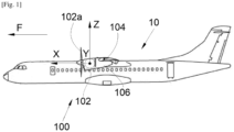
- FIG. 1 shows an aircraft 10 which comprises a propulsion system 102 for example of the turbojet or turboprop type.
- the propulsion system 102 is linked to a wing 104 of the aircraft 10 by means of a reactor mast 106.
- the wing 104 and the reactor mast 106 form an assembly 100 according to the invention and the propulsion system 102 is fixed to the reactor mast 106 by any suitable fixing means known to those skilled in the art such as those disclosed in the document US-A-2016/0221682 .
- X the longitudinal direction of the propulsion system which is horizontal when the aircraft is on the ground
- Y the transverse direction which is horizontal when the aircraft is on the ground
- Z the vertical direction which is vertical when the aircraft is on the ground
- the reactor mast 106 and the propulsion system 102 have a vertical midplane XZ and the propulsion system 102 is here a turboprop with a propeller 102a, but it could be of the double-flow turbojet type with a nacelle.
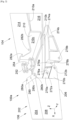
- FIG. 2 shows the assembly 100a according to a first embodiment of the invention and the Fig. 3 shows the assembly 100b according to a second embodiment of the invention.
- the elements common to both embodiments bear the same references.
- the reactor mast 106 comprises a rigid structure forming a box and also called primary structure 202.
- the primary structure 202 is formed of an upper spar 204, a lower spar 206 and two side panels 208 (only the port panel is shown in the figures 1 And 2 ) starboard and port connecting the two longerons 204 and 206.
- the wing structure 104 includes a forward spar 210, an upper surface panel 214 and a lower surface panel 216 which are both attached to the forward spar 210 and extend generally in horizontal planes XY.
- its structure includes other elements such as ribs which are distributed between the extrados panel 214 and the intrados panel 216.
- the front spar 210 here takes the form of a profile in the shape of an inverted Z step on the Fig. 2 , with an upper wing 210a and a lower wing 210b which are generally horizontal and a central portion 210c generally perpendicular to the median plane and extending vertically in the YZ plane.
- the extrados panel 214 is fixed above the upper wing 210a of the spar 210 and the intrados panel 216 is fixed below the lower wing 210b of the spar 210.
- the fixing of the front spar 210 to the panels 214 and 216 is carried out by any suitable means such as for example welds, bolts, etc.
- the extrados panel 214 is thus fixed in the upper part of the front spar 210 and the intrados panel 216 is fixed in the lower part of the front spar 210.
- the central part 210c is at the level of the leading edge of the wing 104.
- the attachment of the engine pylon 106 to the wing 104 differs slightly between the first embodiment and the second embodiment.
- the engine pylon 106 comprises at the rear, a vane 280 which is integral with the primary structure 202 and which extends at the rear of the primary structure 202 in the extension of the upper spar 204.
- the vane 280 thus extends generally horizontally parallel to the XY plane.
- the vane 280 is crossed by three bores 280a-c and the axis of each bore 280a-c of the vane 280 is generally vertical.
- the third bore 280c is generally in the median plane and the first bore 280a and the second bore 280b are on either side of the median plane.
- the pallet 280 thus extends in the upper part of the primary structure 202 towards the front spar 210 of the wing 104 and opposite the extrados panel 214.
- the extrados panel 214 is crossed by two bores 282a-b and the axis of each bore 282a-b of the extrados panel 214 is parallel to the axes of the bores 280a-c of the pallet 280 and is therefore generally vertical.
- the upper surface panel 214 comprises a plate 302 which is integral with the upper surface panel 214, which extends forward and which is crossed by the two bores 282a-b of the upper surface panel 214.
- the plate 302 thus extends forward from the front end of the upper surface panel 214 in the area of the leading edge of the wing 104.
- the bores 282a-b of the extrados panel 214 are on either side of the median plane and are aligned respectively with the first bore 280a and the second bore 280b parallel to the longitudinal direction X.
- the assembly 100a-b comprises a first set of shackles 252, here starboard, and a second set of shackles 254, here port, and each set of shackles 252, 254 consists of two identical shackles superimposed vertically.
- the shackles 252 of the first set have two attachment points and the shackles 254 of the second set have three attachment points, but in another embodiment not shown, the shackles 252 with two points and the shackles 254 with three points can be reversed from starboard to port and vice versa.
- One of the shackle sets 252, 254, here the first shackle set 252 consists of two first shackles 252, each having two bores.
- the two first shackles 252 are arranged vertically on either side of the pallet 280 where a first bore of each first shackle 252 is coaxially aligned with the first bore 280a of the pallet 280.
- a pin is threaded through the first bore of each first shackle 252 and the first bore 280a of the pallet 280 to form a connection point in the form of a pivot connection about a generally vertical axis.
- the first two shackles 252 are arranged vertically on either side of the upper surface panel 214 where a second bore of each first shackle 252 is coaxially aligned with the fourth bore 282a of the upper surface panel 214.
- a pin is threaded through the second bore of each first shackle 252 and the fourth bore 282a of the upper surface panel 214 to form a connection point in the form of a pivot connection about a generally vertical axis.
- the other of the sets of shackles 252, 254, here the second set of shackles 254, consists of two second shackles 254 each having three bores.
- the second two shackles 254 are arranged vertically on either side of the pallet 280 where a first bore of each second shackle 254 is coaxially aligned with the second bore 280b of the pallet 280 and where a second bore of each second shackle 254 is coaxially aligned with the third bore 280c of the pallet 280.
- a pin is threaded through the first bore of each second shackle 254 and the second bore 280b of the pallet 280 to form a connection point in the form of a pivot connection about a generally vertical axis.
- a pin is threaded through the second bore of each second shackle 254 and the third bore 280c of the pallet 280 to form a connection point in the form of a pivot connection about a generally vertical axis.
- the two second shackles 254 are arranged vertically on either side of the upper surface panel 214 where a third bore of each second shackle 254 is coaxially aligned with the fifth bore 282b of the upper surface panel 214.
- a pin is threaded through the third bore of each second shackle 254 and the fifth bore 282b of the upper surface panel 214 to form a connection point in the form of a pivot connection about a generally vertical axis.
- the reactor mast 106 comprises, at the rear of the primary structure 202, two starboard 270a and port 270b fixing lugs which are integral with the primary structure 202 and which extend at the rear of the primary structure 202 in the extension respectively of the starboard side panel and the port side panel 208.
- the fixing lugs 270a-b thus extend on the starboard and port sides of the primary structure 202 towards the front spar 210.
- Each fixing lug 270a-b thus extends generally in a vertical plane parallel to the XZ plane and they are on either side of the median plane.
- Each fixing lug 270a-b is crossed by a sixth bore 272a-b, respectively starboard and port and the axis of each sixth bore 272a-b is generally horizontal.
- the assembly 100a-b also comprises two fittings 274a-b, namely a starboard fitting 274a and a port fitting 274b which are arranged on either side of the median plane and each is fixed under the intrados panel 216 by any suitable means such as welds, bolts, etc.
- Each fitting 274a-b has a female yoke 276a-b, namely a starboard female yoke 276a into which the starboard fixing lug 270a is inserted and a port female yoke 276b into which the port fixing lug 270b is inserted.
- Each female yoke 276a-b is crossed by a seventh bore 278a-b whose axis is coaxial with the axis of the sixth bore 272a-b of the fixing lug 270a-b which is inserted therein, that is to say generally horizontal.
- connection between a fitting 274a-b and the associated fixing lug 270a-b is ensured by the installation of an axis which is threaded into the associated bores, i.e. the female yoke 276a-b and the fixing lug 270a-b, and takes the form of a pivot connection around a generally horizontal axis.
- the transverse forces (Ty) are transmitted through the two port shackles 254.
- the vertical forces (Tz) are transmitted through the connections between the female yokes 276a-b and the fixing lugs 270a-b.
- the torsional moment Mx about the longitudinal direction X is compensated at the connections between the female yokes 276a-b and the fixing lugs 270a-b.
- the bending moment My about the transverse direction Y and the bending moment Mz about the vertical direction Z are compensated at the level of the connections between the female clevises 276a-b and the fixing lugs 270a-b and at the level of the sets of shackles 252 and 254 arranged on either side of the vertical median plane, to starboard and port.
Landscapes
- Engineering & Computer Science (AREA)
- Aviation & Aerospace Engineering (AREA)
- Structures Of Non-Positive Displacement Pumps (AREA)
- Connection Of Plates (AREA)
- Mutual Connection Of Rods And Tubes (AREA)
- Jib Cranes (AREA)
Claims (3)
- Anordnung (100, l00a-b) zur Montage, an einem Flugzeug (10), eines Antriebssystems (102), das eine vertikale Mittelebene (XZ) aufweist, wobei die Anordnung (100, l00a-b) Folgendes umfasst:- eine Tragfläche (104) mit einem Vorderholm (210), einer Oberseitenplatte (214) und einer Unterseitenplatte (216), die jeweils oben am Vorderholm (210) bzw. unten am Vorderholm (210) befestigt sind, wobei die Oberseitenplatte (214) vertikal von einer vierten Bohrung (282a) und einer fünften Bohrung (282b) durchquert wird,- einen Triebwerkspylon (106), umfassend eine Primärstruktur (202), einen Ansatz (280), der mit der Primärstruktur (202) fest verbunden ist und sich hinten und oben von der Primärstruktur (202) erstreckt, und zwei Befestigungslaschen, eine steuerbordseitige (270a) und eine backbordseitige (270b), die mit der Primärstruktur (202) fest verbunden sind und sich hinten und an den Seiten der Primärstruktur (202) erstrecken, wobei der Ansatz (280) vertikal von einer ersten Bohrung (280a), einer zweiten Bohrung (280b) und einer dritten Bohrung (280c) durchquert wird, wobei jede Befestigungslasche (270a-b) horizontal von einer sechsten Bohrung (272a-b) durchquert wird, und- einen steuerbordseitigen Beschlag (274a) und einen backbordseitigen Beschlag (274b), die jeweils einen steuerbordseitigen Gabelkopf (276a), in den die steuerbordseitige Befestigungslasche (270a) eingeführt ist, und einen backbordseitigen Gabelkopf (276b), in den die backbordseitige Befestigungslasche (270b) eingeführt ist, aufweisen, wobei jeder Gabelkopf (276a-b) von einer siebten Bohrung (278a-b) durchquert wird, deren Achse koaxial zu der Achse der sechsten Bohrung (272a-b) der Befestigungslasche (270a-b), die darin eingeführt ist, ist, und wobei in die so ausgerichteten assoziierten Bohrungen eine Achse eingesteckt istwobei die Anordnung (100, l00a-b) dadurch gekennzeichnet ist, dass der steuerbordseitige Beschlag (274a) und der backbordseitige Beschlag (274b) unter der Unterseitenplatte (216) befestigt sind und dass die Anordnung (100, l00a-b) ferner Folgendes umfasst:- zwei erste Bügel (252), die vertikal zu beiden Seiten des Ansatzes (280) und der Oberseitenplatte (214) angeordnet sind, wobei eine erste Bohrung jedes ersten Bügels (252) koaxial zu der ersten Bohrung (280a) des Ansatzes (280) ausgerichtet ist und eine Achse in die so ausgerichteten Bohrungen eingesteckt ist, wobei eine zweite Bohrung jedes ersten Bügels (252) koaxial zu der vierten Bohrung (282a) der Oberseitenplatte (214) ausgerichtet ist und eine Achse in die so ausgerichteten Bohrungen eingesteckt ist, und- zwei zweite Bügel (254), die vertikal zu beiden Seiten des Ansatzes (280) und der Oberseitenplatte (214) angeordnet sind, wobei eine erste Bohrung jedes zweiten Bügels (254) koaxial zu der zweiten Bohrung (280b) des Ansatzes (280) ausgerichtet ist und eine Achse in die so ausgerichteten Bohrungen eingesteckt ist, wobei eine zweite Bohrung jedes zweiten Bügels (254) koaxial zu der dritten Bohrung (280c) des Ansatzes (280) ausgerichtet ist und eine Achse in die so ausgerichteten Bohrungen eingesteckt ist, wobei eine dritte Bohrung jedes zweiten Bügels (254) koaxial zu der fünften Bohrung (282b) der Oberseitenplatte (214) ausgerichtet ist und eine Achse in die so ausgerichteten Bohrungen eingesteckt ist.
- Anordnung (100b) nach Anspruch 1, dadurch gekennzeichnet, dass die Oberseitenplatte (214) eine Tafel (302) umfasst, die fest mit der Oberseitenplatte (214) verbunden ist, und dass die zwei Bohrungen (282ab) der Oberseitenplatte (214) in der Tafel (302) ausgeführt sind.
- Flugzeug (10), das ein Antriebssystem (102) und eine Anordnung (100) nach einem der Ansprüche 1 oder 2 umfasst, wobei das Antriebssystem (102) an dem Triebwerkspylon (106) befestigt ist.
Applications Claiming Priority (1)
| Application Number | Priority Date | Filing Date | Title |
|---|---|---|---|
| FR2211634A FR3141676A1 (fr) | 2022-11-08 | 2022-11-08 | Ensemble pour un aéronef comportant une aile et un mât réacteur pour coupler un système de propulsion à ladite aile |
Publications (2)
| Publication Number | Publication Date |
|---|---|
| EP4368512A1 EP4368512A1 (de) | 2024-05-15 |
| EP4368512B1 true EP4368512B1 (de) | 2025-05-14 |
Family
ID=85017726
Family Applications (1)
| Application Number | Title | Priority Date | Filing Date |
|---|---|---|---|
| EP23207860.0A Active EP4368512B1 (de) | 2022-11-08 | 2023-11-06 | Anordnung für ein flugzeug mit einem flügel und einem reaktormast zur kopplung eines antriebssystems an den flügel |
Country Status (4)
| Country | Link |
|---|---|
| US (1) | US12337978B2 (de) |
| EP (1) | EP4368512B1 (de) |
| CN (1) | CN118004431A (de) |
| FR (1) | FR3141676A1 (de) |
Families Citing this family (2)
| Publication number | Priority date | Publication date | Assignee | Title |
|---|---|---|---|---|
| US20260015096A1 (en) * | 2024-07-15 | 2026-01-15 | The Boeing Company | Structure for transferring a lateral load of an engine pylon to an aircraft wing |
| FR3167623A1 (fr) * | 2024-10-18 | 2026-04-24 | Airbus Operations (S.A.S.) | Ensemble pour aéronef comportant des moyens pour fixer une aile à un mât réacteur |
Family Cites Families (14)
| Publication number | Priority date | Publication date | Assignee | Title |
|---|---|---|---|---|
| GB8300748D0 (en) * | 1983-01-12 | 1983-02-16 | British Aerospace | Power plant attachment for aircraft wings |
| GB9927425D0 (en) * | 1999-11-20 | 2000-01-19 | Rolls Royce Plc | A gas turbine engine mounting arrangement |
| US7083143B2 (en) * | 2003-10-17 | 2006-08-01 | The Boeing Company | Apparatuses and methods for attaching engines and other structures to aircraft wings |
| FR2905932B1 (fr) * | 2006-09-20 | 2008-12-05 | Airbus France Sa | Agencement pour attache de dispositif d'accrochage d'un moteur d'aeronef |
| US8205825B2 (en) * | 2008-02-27 | 2012-06-26 | Spirit Aerosystems, Inc. | Engine pylon made from composite material |
| FR3012793B1 (fr) * | 2013-11-05 | 2017-05-05 | Airbus Operations Sas | Ensemble pour aeronef comprenant une ferrure fixee sur la partie extrados d'un caisson de voilure, pour le montage d'un mat d'accrochage sur ce caisson de voilure |
| US9238511B2 (en) * | 2014-03-04 | 2016-01-19 | Mra Systems, Inc. | Engine pylon structure |
| FR3032180B1 (fr) | 2015-01-30 | 2018-05-18 | Airbus Operations | Ensemble propulsif comportant un turboreacteur et un mat d'accrochage permettant une nouvelle distribution des efforts entre le turboreacteur et la voilure |
| FR3032421B1 (fr) * | 2015-02-06 | 2017-03-10 | Airbus Operations Sas | Ensemble pour aeronef comprenant une structure primaire de mat d'accrochage integree a la structure de l'element de voilure |
| US10144525B2 (en) * | 2015-09-24 | 2018-12-04 | Embraer S.A. | Aircraft engine pylon to wing mounting assembly |
| US10583930B2 (en) * | 2017-06-02 | 2020-03-10 | Spirit Aerosystems, Inc. | Aircraft engine attachment assembly |
| FR3099464B1 (fr) * | 2019-07-31 | 2024-06-21 | Airbus Operations Sas | Mat reacteur pour coupler un turboreacteur a une aile d’un aeronef |
| FR3102151B1 (fr) * | 2019-10-21 | 2021-10-29 | Airbus Operations Sas | Aéronef comprenant une attache voilure arrière présentant au moins deux bielles latérales et un pion de cisaillement |
| EP3939891B1 (de) * | 2020-07-17 | 2023-04-26 | Airbus Operations (S.A.S.) | Anordnung für ein luftfahrzeug aus einem flügel und einem triebwerksträger zur ankopplung eines turbotriebwerks an diesen flügel |
-
2022
- 2022-11-08 FR FR2211634A patent/FR3141676A1/fr not_active Ceased
-
2023
- 2023-11-06 EP EP23207860.0A patent/EP4368512B1/de active Active
- 2023-11-06 US US18/502,248 patent/US12337978B2/en active Active
- 2023-11-07 CN CN202311473647.1A patent/CN118004431A/zh active Pending
Also Published As
| Publication number | Publication date |
|---|---|
| CN118004431A (zh) | 2024-05-10 |
| EP4368512A1 (de) | 2024-05-15 |
| FR3141676A1 (fr) | 2024-05-10 |
| US12337978B2 (en) | 2025-06-24 |
| US20240150028A1 (en) | 2024-05-09 |
Similar Documents
| Publication | Publication Date | Title |
|---|---|---|
| EP4368512B1 (de) | Anordnung für ein flugzeug mit einem flügel und einem reaktormast zur kopplung eines antriebssystems an den flügel | |
| EP2139769B1 (de) | Befestigung für pylonkasten an flügeln, festklemmen einer seitenplatte des kastens | |
| EP2170704B1 (de) | Vorrichtung zur kupplung eines luftfahrzeugtriebwerks und verfahren zur befestigung eines luftfahrzeugtriebwerks mittels solch einer vorrichtung | |
| EP2142430B1 (de) | Befestigungsvorrichtung für flugzeugtriebwerk und mindestens eine solche vorrichtung enthaltendes flugzeug | |
| EP2500268B1 (de) | Aufhängesäule eines Flugzeugmotors | |
| EP2137072B1 (de) | Vorrichtung zur befestigung eines flugzeugtriebwerks und flugzeug mit mindestens einer derartigen vorrichtung | |
| EP3505439B1 (de) | Einheit für ein luftfahrzeug, die eine primärstruktur eines aufhängungsmasts umfasst, die an einem flügelkasten durch befestigungselemente befestigt ist und im vorderkantenbereich ein reduziertes volumen aufweist | |
| EP3505448B1 (de) | Einheit für ein luftfahrzeug, die eine primärstruktur eines aufhängungsmasts umfasst, die an einem flügelkasten mithilfe von anschlüssen reduzierten volumens in der vorderkantenzone befestigt ist | |
| EP3521173B1 (de) | Einheit für luftfahrzeug, die eine primärstruktur einer aufhängesäule umfasst, die an einem fahrwerkskasten mithilfe einer verschraubten verbindung befestigt ist | |
| EP3486174B1 (de) | Hintere motorbefestigung für einen luftfahrzeugmotor | |
| EP3939891B1 (de) | Anordnung für ein luftfahrzeug aus einem flügel und einem triebwerksträger zur ankopplung eines turbotriebwerks an diesen flügel | |
| FR3099464A1 (fr) | Mat reacteur pour coupler un turboreacteur a une aile d’un aeronef | |
| FR3156756A1 (fr) | Ensemble propulsif pour aéronef comportant un moteur, un mât et des moyens d’accrochage du moteur au mât | |
| FR3103788A1 (fr) | Ensemble pour un aeronef, ledit ensemble comportant un mat, une aile et un systeme de fixation entre le mat et l’aile | |
| EP4491518B1 (de) | Flugzeugtriebwerkanordnung mit einer hauptstange zur motorbefestigung, sowie zwei parallel an einer querverstärkung vor einer primärstruktur eines masts | |
| FR3083776A1 (fr) | Mat d'accrochage pour un turboreacteur d'un aeronef comportant une structure particuliere | |
| EP4183690B1 (de) | Triebwerksmast zur kopplung eines strahltriebwerks an einen flügel eines flugzeugs | |
| EP4467461B1 (de) | Anordnung für ein flugzeug mit einem flügel und einem triebwerkmast zur kopplung eines antriebssystems an den flügel | |
| EP4488178B1 (de) | Montage eines befestigungsmastes mit einem flugzeugmotor | |
| EP4516677A1 (de) | Anordnung für ein luftfahrzeug mit einem flügel und einem strahltriebwerk-pylon zur kopplung eines antriebssystems an den flügel | |
| EP4112477A1 (de) | Luftfahrzeug-triebwerkseinheit mit einer vorderen triebwerksaufhängung mit einem querträger, der teilweise gegenüber einer vorderen querverstärkung einer primärstruktur eines mastes positioniert ist | |
| EP4442577B1 (de) | Reaktormast zur befestigung eines flugzeugmotors | |
| FR3049264B1 (fr) | Systeme de montage pour un aeronef, destine a la fixation d’un moteur sur un mat d’attache. | |
| EP4729415A1 (de) | Flugzeug mit mindestens einem tragflächenbefestigungssystem zur optimalen übertragung von schubkräften | |
| EP4656513A1 (de) | Luftfahrzeug mit mindestens einem flügelbefestigungssystem, das mindestens eine seitenstange aufweist |
Legal Events
| Date | Code | Title | Description |
|---|---|---|---|
| PUAI | Public reference made under article 153(3) epc to a published international application that has entered the european phase |
Free format text: ORIGINAL CODE: 0009012 |
|
| STAA | Information on the status of an ep patent application or granted ep patent |
Free format text: STATUS: THE APPLICATION HAS BEEN PUBLISHED |
|
| AK | Designated contracting states |
Kind code of ref document: A1 Designated state(s): AL AT BE BG CH CY CZ DE DK EE ES FI FR GB GR HR HU IE IS IT LI LT LU LV MC ME MK MT NL NO PL PT RO RS SE SI SK SM TR |
|
| STAA | Information on the status of an ep patent application or granted ep patent |
Free format text: STATUS: REQUEST FOR EXAMINATION WAS MADE |
|
| 17P | Request for examination filed |
Effective date: 20241113 |
|
| RBV | Designated contracting states (corrected) |
Designated state(s): AL AT BE BG CH CY CZ DE DK EE ES FI FR GB GR HR HU IE IS IT LI LT LU LV MC ME MK MT NL NO PL PT RO RS SE SI SK SM TR |
|
| GRAP | Despatch of communication of intention to grant a patent |
Free format text: ORIGINAL CODE: EPIDOSNIGR1 |
|
| STAA | Information on the status of an ep patent application or granted ep patent |
Free format text: STATUS: GRANT OF PATENT IS INTENDED |
|
| RIC1 | Information provided on ipc code assigned before grant |
Ipc: B64D 27/12 20060101ALN20241205BHEP Ipc: B64D 27/40 20240101AFI20241205BHEP |
|
| RIC1 | Information provided on ipc code assigned before grant |
Ipc: B64D 27/12 20060101ALN20241210BHEP Ipc: B64D 27/40 20240101AFI20241210BHEP |
|
| INTG | Intention to grant announced |
Effective date: 20241220 |
|
| GRAS | Grant fee paid |
Free format text: ORIGINAL CODE: EPIDOSNIGR3 |
|
| GRAA | (expected) grant |
Free format text: ORIGINAL CODE: 0009210 |
|
| STAA | Information on the status of an ep patent application or granted ep patent |
Free format text: STATUS: THE PATENT HAS BEEN GRANTED |
|
| AK | Designated contracting states |
Kind code of ref document: B1 Designated state(s): AL AT BE BG CH CY CZ DE DK EE ES FI FR GB GR HR HU IE IS IT LI LT LU LV MC ME MK MT NL NO PL PT RO RS SE SI SK SM TR |
|
| REG | Reference to a national code |
Ref country code: GB Ref legal event code: FG4D Free format text: NOT ENGLISH |
|
| REG | Reference to a national code |
Ref country code: CH Ref legal event code: EP |
|
| REG | Reference to a national code |
Ref country code: DE Ref legal event code: R096 Ref document number: 602023003496 Country of ref document: DE |
|
| REG | Reference to a national code |
Ref country code: IE Ref legal event code: FG4D Free format text: LANGUAGE OF EP DOCUMENT: FRENCH |
|
| REG | Reference to a national code |
Ref country code: NL Ref legal event code: MP Effective date: 20250514 |
|
| PG25 | Lapsed in a contracting state [announced via postgrant information from national office to epo] |
Ref country code: FI Free format text: LAPSE BECAUSE OF FAILURE TO SUBMIT A TRANSLATION OF THE DESCRIPTION OR TO PAY THE FEE WITHIN THE PRESCRIBED TIME-LIMIT Effective date: 20250514 Ref country code: PT Free format text: LAPSE BECAUSE OF FAILURE TO SUBMIT A TRANSLATION OF THE DESCRIPTION OR TO PAY THE FEE WITHIN THE PRESCRIBED TIME-LIMIT Effective date: 20250915 Ref country code: ES Free format text: LAPSE BECAUSE OF FAILURE TO SUBMIT A TRANSLATION OF THE DESCRIPTION OR TO PAY THE FEE WITHIN THE PRESCRIBED TIME-LIMIT Effective date: 20250514 |
|
| REG | Reference to a national code |
Ref country code: LT Ref legal event code: MG9D |
|
| PG25 | Lapsed in a contracting state [announced via postgrant information from national office to epo] |
Ref country code: NO Free format text: LAPSE BECAUSE OF FAILURE TO SUBMIT A TRANSLATION OF THE DESCRIPTION OR TO PAY THE FEE WITHIN THE PRESCRIBED TIME-LIMIT Effective date: 20250814 Ref country code: GR Free format text: LAPSE BECAUSE OF FAILURE TO SUBMIT A TRANSLATION OF THE DESCRIPTION OR TO PAY THE FEE WITHIN THE PRESCRIBED TIME-LIMIT Effective date: 20250815 |
|
| PG25 | Lapsed in a contracting state [announced via postgrant information from national office to epo] |
Ref country code: NL Free format text: LAPSE BECAUSE OF FAILURE TO SUBMIT A TRANSLATION OF THE DESCRIPTION OR TO PAY THE FEE WITHIN THE PRESCRIBED TIME-LIMIT Effective date: 20250514 Ref country code: PL Free format text: LAPSE BECAUSE OF FAILURE TO SUBMIT A TRANSLATION OF THE DESCRIPTION OR TO PAY THE FEE WITHIN THE PRESCRIBED TIME-LIMIT Effective date: 20250514 |
|
| REG | Reference to a national code |
Ref country code: AT Ref legal event code: MK05 Ref document number: 1794617 Country of ref document: AT Kind code of ref document: T Effective date: 20250514 |
|
| PG25 | Lapsed in a contracting state [announced via postgrant information from national office to epo] |
Ref country code: BG Free format text: LAPSE BECAUSE OF FAILURE TO SUBMIT A TRANSLATION OF THE DESCRIPTION OR TO PAY THE FEE WITHIN THE PRESCRIBED TIME-LIMIT Effective date: 20250514 |
|
| PG25 | Lapsed in a contracting state [announced via postgrant information from national office to epo] |
Ref country code: HR Free format text: LAPSE BECAUSE OF FAILURE TO SUBMIT A TRANSLATION OF THE DESCRIPTION OR TO PAY THE FEE WITHIN THE PRESCRIBED TIME-LIMIT Effective date: 20250514 |
|
| PG25 | Lapsed in a contracting state [announced via postgrant information from national office to epo] |
Ref country code: AT Free format text: LAPSE BECAUSE OF FAILURE TO SUBMIT A TRANSLATION OF THE DESCRIPTION OR TO PAY THE FEE WITHIN THE PRESCRIBED TIME-LIMIT Effective date: 20250514 |
|
| PG25 | Lapsed in a contracting state [announced via postgrant information from national office to epo] |
Ref country code: RS Free format text: LAPSE BECAUSE OF FAILURE TO SUBMIT A TRANSLATION OF THE DESCRIPTION OR TO PAY THE FEE WITHIN THE PRESCRIBED TIME-LIMIT Effective date: 20250814 |
|
| PG25 | Lapsed in a contracting state [announced via postgrant information from national office to epo] |
Ref country code: IS Free format text: LAPSE BECAUSE OF FAILURE TO SUBMIT A TRANSLATION OF THE DESCRIPTION OR TO PAY THE FEE WITHIN THE PRESCRIBED TIME-LIMIT Effective date: 20250914 |
|
| PG25 | Lapsed in a contracting state [announced via postgrant information from national office to epo] |
Ref country code: LV Free format text: LAPSE BECAUSE OF FAILURE TO SUBMIT A TRANSLATION OF THE DESCRIPTION OR TO PAY THE FEE WITHIN THE PRESCRIBED TIME-LIMIT Effective date: 20250514 |
|
| PGFP | Annual fee paid to national office [announced via postgrant information from national office to epo] |
Ref country code: DE Payment date: 20251119 Year of fee payment: 3 |
|
| PG25 | Lapsed in a contracting state [announced via postgrant information from national office to epo] |
Ref country code: DK Free format text: LAPSE BECAUSE OF FAILURE TO SUBMIT A TRANSLATION OF THE DESCRIPTION OR TO PAY THE FEE WITHIN THE PRESCRIBED TIME-LIMIT Effective date: 20250514 Ref country code: SM Free format text: LAPSE BECAUSE OF FAILURE TO SUBMIT A TRANSLATION OF THE DESCRIPTION OR TO PAY THE FEE WITHIN THE PRESCRIBED TIME-LIMIT Effective date: 20250514 |
|
| PGFP | Annual fee paid to national office [announced via postgrant information from national office to epo] |
Ref country code: FR Payment date: 20251126 Year of fee payment: 3 |
|
| PG25 | Lapsed in a contracting state [announced via postgrant information from national office to epo] |
Ref country code: CZ Free format text: LAPSE BECAUSE OF FAILURE TO SUBMIT A TRANSLATION OF THE DESCRIPTION OR TO PAY THE FEE WITHIN THE PRESCRIBED TIME-LIMIT Effective date: 20250514 |
|
| PG25 | Lapsed in a contracting state [announced via postgrant information from national office to epo] |
Ref country code: EE Free format text: LAPSE BECAUSE OF FAILURE TO SUBMIT A TRANSLATION OF THE DESCRIPTION OR TO PAY THE FEE WITHIN THE PRESCRIBED TIME-LIMIT Effective date: 20250514 |
|
| PG25 | Lapsed in a contracting state [announced via postgrant information from national office to epo] |
Ref country code: SK Free format text: LAPSE BECAUSE OF FAILURE TO SUBMIT A TRANSLATION OF THE DESCRIPTION OR TO PAY THE FEE WITHIN THE PRESCRIBED TIME-LIMIT Effective date: 20250514 |
|
| PG25 | Lapsed in a contracting state [announced via postgrant information from national office to epo] |
Ref country code: IT Free format text: LAPSE BECAUSE OF FAILURE TO SUBMIT A TRANSLATION OF THE DESCRIPTION OR TO PAY THE FEE WITHIN THE PRESCRIBED TIME-LIMIT Effective date: 20250514 |
|
| REG | Reference to a national code |
Ref country code: DE Ref legal event code: R097 Ref document number: 602023003496 Country of ref document: DE |
|
| PG25 | Lapsed in a contracting state [announced via postgrant information from national office to epo] |
Ref country code: RO Free format text: LAPSE BECAUSE OF FAILURE TO SUBMIT A TRANSLATION OF THE DESCRIPTION OR TO PAY THE FEE WITHIN THE PRESCRIBED TIME-LIMIT Effective date: 20250514 |
|
| PLBE | No opposition filed within time limit |
Free format text: ORIGINAL CODE: 0009261 |
|
| STAA | Information on the status of an ep patent application or granted ep patent |
Free format text: STATUS: NO OPPOSITION FILED WITHIN TIME LIMIT |
|
| REG | Reference to a national code |
Ref country code: CH Ref legal event code: L10 Free format text: ST27 STATUS EVENT CODE: U-0-0-L10-L00 (AS PROVIDED BY THE NATIONAL OFFICE) Effective date: 20260325 |
|
| 26N | No opposition filed |
Effective date: 20260217 |