EP4467461B1 - Anordnung für ein flugzeug mit einem flügel und einem triebwerkmast zur kopplung eines antriebssystems an den flügel - Google Patents
Anordnung für ein flugzeug mit einem flügel und einem triebwerkmast zur kopplung eines antriebssystems an den flügel Download PDFInfo
- Publication number
- EP4467461B1 EP4467461B1 EP24175736.8A EP24175736A EP4467461B1 EP 4467461 B1 EP4467461 B1 EP 4467461B1 EP 24175736 A EP24175736 A EP 24175736A EP 4467461 B1 EP4467461 B1 EP 4467461B1
- Authority
- EP
- European Patent Office
- Prior art keywords
- fastened
- starboard
- fastening
- assembly
- connection
- Prior art date
- Legal status (The legal status is an assumption and is not a legal conclusion. Google has not performed a legal analysis and makes no representation as to the accuracy of the status listed.)
- Active
Links
Images
Classifications
-
- B—PERFORMING OPERATIONS; TRANSPORTING
- B64—AIRCRAFT; AVIATION; COSMONAUTICS
- B64D—EQUIPMENT FOR FITTING IN OR TO AIRCRAFT; FLIGHT SUITS; PARACHUTES; ARRANGEMENT OR MOUNTING OF POWER PLANTS OR PROPULSION TRANSMISSIONS IN AIRCRAFT
- B64D27/00—Arrangement or mounting of power plants in aircraft; Aircraft characterised by the type or position of power plants
- B64D27/02—Aircraft characterised by the type or position of power plants
- B64D27/10—Aircraft characterised by the type or position of power plants of gas-turbine type
- B64D27/12—Aircraft characterised by the type or position of power plants of gas-turbine type within, or attached to, wings
-
- B—PERFORMING OPERATIONS; TRANSPORTING
- B64—AIRCRAFT; AVIATION; COSMONAUTICS
- B64C—AEROPLANES; HELICOPTERS
- B64C3/00—Wings
- B64C3/32—Wings specially adapted for mounting power plant
-
- B—PERFORMING OPERATIONS; TRANSPORTING
- B64—AIRCRAFT; AVIATION; COSMONAUTICS
- B64D—EQUIPMENT FOR FITTING IN OR TO AIRCRAFT; FLIGHT SUITS; PARACHUTES; ARRANGEMENT OR MOUNTING OF POWER PLANTS OR PROPULSION TRANSMISSIONS IN AIRCRAFT
- B64D27/00—Arrangement or mounting of power plants in aircraft; Aircraft characterised by the type or position of power plants
- B64D27/02—Aircraft characterised by the type or position of power plants
- B64D27/16—Aircraft characterised by the type or position of power plants of jet type
- B64D27/18—Aircraft characterised by the type or position of power plants of jet type within, or attached to, wings
-
- B—PERFORMING OPERATIONS; TRANSPORTING
- B64—AIRCRAFT; AVIATION; COSMONAUTICS
- B64D—EQUIPMENT FOR FITTING IN OR TO AIRCRAFT; FLIGHT SUITS; PARACHUTES; ARRANGEMENT OR MOUNTING OF POWER PLANTS OR PROPULSION TRANSMISSIONS IN AIRCRAFT
- B64D27/00—Arrangement or mounting of power plants in aircraft; Aircraft characterised by the type or position of power plants
- B64D27/40—Arrangements for mounting power plants in aircraft
- B64D27/404—Suspension arrangements specially adapted for supporting vertical loads
-
- B—PERFORMING OPERATIONS; TRANSPORTING
- B64—AIRCRAFT; AVIATION; COSMONAUTICS
- B64D—EQUIPMENT FOR FITTING IN OR TO AIRCRAFT; FLIGHT SUITS; PARACHUTES; ARRANGEMENT OR MOUNTING OF POWER PLANTS OR PROPULSION TRANSMISSIONS IN AIRCRAFT
- B64D27/00—Arrangement or mounting of power plants in aircraft; Aircraft characterised by the type or position of power plants
- B64D27/40—Arrangements for mounting power plants in aircraft
- B64D27/402—Arrangements for mounting power plants in aircraft comprising box like supporting frames, e.g. pylons or arrangements for embracing the power plant
Definitions
- Said body comprises two first starboard and port fixing clevises extending to the rear and in the upper part on the sides of said fixing base, each of said first fixing clevises being fixed to one of said second fittings by a first pivot connection.
- Said body also comprises two second starboard and port fixing yokes extending to the rear and in the lower part on the sides of said fixing base, each of said two second fixing yokes being fixed by a second connection to a second end respectively of the first and second connecting rods.
- Said second connection has at least one degree of freedom in rotation.
- Said body further comprises at least a third central fixing yoke extending to the rear and at the level of the vertical median plane, said third central fixing yoke being fixed to a second end of said third connecting rod by a sixth connection, said sixth connection having at least one degree of freedom in rotation.
- the assembly comprises a fourth starboard fitting and a fourth port fitting, each of said fourth fittings being fixed to the primary structure of the engine pylon.
- the assembly comprises a fourth connecting rod, a first end of which is fixed to said fourth fitting by an eighth pivot connection.
- said body comprises two fourth starboard and port fixing clevises extending at the front and in the lower part on the sides of said fixing base, each of said fourth fixing clevises being fixed to a second end of a fourth connecting rod by a ninth pivot connection.
- the engine forces that are carried by the primary structure of the mast are transmitted directly to the upper and lower panels via the mounting base.
- the implementation of the fourth connecting rods connecting the primary structure of the reactor mast to the mounting base makes it possible to reduce the dimensions of the primary structure of the reactor mast, thus allowing and facilitating the attachment of turbojet engines of larger dimensions to the aircraft wing.
- said primary structure comprises an upper spar, a lower spar and two starboard and port side panels connecting the two spars, said fourth fittings being fixed on either side of said primary structure in the lower part of said side panels.
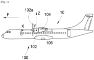
- X the longitudinal direction of the propulsion system which is horizontal when the aircraft is on the ground
- Y the transverse direction which is horizontal when the aircraft is on the ground
- Z the vertical direction which is vertical when the aircraft is on the ground
- the wing structure 104 includes a forward spar 210, an upper surface panel 214 and a lower surface panel 216 which are both attached to the forward spar 210 and extend generally in horizontal planes XY.
- its structure includes other elements such as ribs which are distributed between the extrados panel 214 and the intrados panel 216.
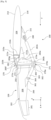
- the front spar 210 here takes the form of a profile in the shape of an inverted Z step on the Figs. 2 And 3 , with an upper wing 210a (also called upper part) and a lower wing 210b (also called lower part) which are generally horizontal and a central part 210c generally perpendicular to the median plane and extending generally vertically parallel to the YZ plane.
- the extrados panel 214 is fixed above the upper wing 210a of the spar 210 and the intrados panel 216 is fixed below the lower wing 210b of the spar 210.
- the attachment of the front spar 210 to the panels 214 and 216 is carried out by any suitable means such as welds, bolts, etc.
- the extrados panel 214 is thus fixed in the upper part of the front spar 210 and the intrados panel 216 is fixed in the lower part of the front spar 210.
- the central part 210c is at the level of the leading edge of the wing 104.
- the front spar 210 carries a first fitting 211a fixed at the level of the vertical median plane XZ and more particularly here to the central part 210c of the front spar 210.
- the lower surface panel 216 carries two second fittings, starboard 211b' and port 211b (only the second port fitting is shown in the drawings). Figs. 2 And 3 , the second starboard fitting is shown on the Fig. 4 ) which are fixed on the external face of the intrados panel 216 and in alignment with the lower part 210b of the front side member 210.
- the intrados panel 216 also carries a third fitting 221 (visible on the Fig.
- the third fitting 221 is positioned at the rear of the second starboard 211b' and port 211b fittings.
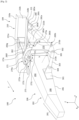
- the assembly 100 further comprises a fixing base 270 secured to the rear part of the primary structure 202.
- the fixing base 270 comprises in this example a body 270a extending vertically in the YZ plane. More precisely, the body 270a has a first body part 272 in the form of an inverted U as well as a second body part 271 also having the shape of an inverted U.
- the first body part 272 and the second body part 271 extend in a vertical plane parallel to the vertical plane YZ and the first body part 272 is arranged inside the second body part 271.
- the first body portion 272 comprises a central upper wall 272a extending horizontally in a plane parallel to the XY plane.
- the first body portion 272 also comprises two starboard 272b' and port 272b side walls (only the port side wall is shown in the Figs. 2 And 3 , the starboard side wall is visible on the Fig. 4 ) which extend perpendicularly from the central upper wall 272a and which extend vertically in planes parallel to the vertical median plane XZ.
- the central upper wall 272a and the starboard 272b' and port 272b side walls are integral and extend around and above the rear portion of the primary structure 202 and form a housing 273 for receiving the base 203 of the primary structure 202.
- the dimensions of the housing 273 are obviously chosen to correspond to the dimensions of the base 203 of the primary structure 202. It is understood that the primary structure 202 is fixed to the housing 273 by any suitable means such as welds, bolts, etc.
- the fixing base 270 comprises at least one reinforcing rib 272c connecting the walls 272a, 272b, 272b' of the first body part 272 to the second body part 271.
- three ribs 272c are implemented (only two ribs are visible on the Fig. 2 ) and extend respectively from the upper central wall 272a and the starboard 272b' and port 272b side walls to the second body part 271.
- These reinforcing ribs 272c allow in particular the fixing base 270 to support and transmit the forces coming from the propulsion system 102 to the wing 104.
- the ribs 272c fix the walls 272a, 272b, 272b' of the first body part 272 to the walls of the second body part 271.
- the second body part 271 of the body 270a of the fixing base 270 also comprises two second starboard and port fixing yokes 273b (only the second port fixing yoke is shown in the Figs. 2 And 3 ) which extend from the second body part 271 of the body 270a towards the rear and which are arranged in the lower part on the sides of the fixing base 270.
- the two second fixing yokes 273b are integral with a shackle 280 which can be triangular, respectively by a first and a second connecting rod 281a, 281b.
Landscapes
- Engineering & Computer Science (AREA)
- Aviation & Aerospace Engineering (AREA)
- Mechanical Engineering (AREA)
- Pivots And Pivotal Connections (AREA)
- Mutual Connection Of Rods And Tubes (AREA)
- Jib Cranes (AREA)
- Connection Of Plates (AREA)
Claims (9)
- Anordnung (100) zur Montage, an einem Flugzeug (10), eines Antriebssystems (102), das eine vertikale Mittelebene (XZ) aufweist, wobei die Anordnung (100) Folgendes umfasst:- eine Tragfläche (104) mit einem Vorderholm (210), einer Oberseitenplatte (214), die am oberen Teil (210a) des Vorderholms (210) befestigt ist, und einer Unterseitenplatte (216), die am unteren Teil (210b) des Vorderholms (210) befestigt ist, wobei der Vorderholm (210) einen ersten Beschlag (211a) im Bereich der vertikalen Mittelebene (XZ) trägt, wobei die Unterseitenplatte (216) zwei zweite Beschläge, einen steuerbordseitigen (211b') und einen backbordseitigen (211b), im Bereich des unteren Teils (210b) des Vorderholms (210) trägt und wobei die Unterseite (216) einen dritten Beschlag (221) trägt, der hinter den zweiten Beschlägen, dem steuerbordseitigen (211b') und dem backbordseitigen (211b), positioniert ist,- einen Triebwerkspylon (106), der eine Primärstruktur (202) umfasst,- einen Bügel (280), der durch eine fünfte Verbindung (283e) an dem dritten Beschlag (221) der Unterseite (216) befestigt ist, wobei die fünfte Verbindung (283e) mindestens einen Drehfreiheitsgrad aufweist,- eine erste und eine zweite Verbindungsstange (281a, 281b), wobei ein erstes Ende jeder ersten und zweiten Verbindungsstange (281a, 281b) durch eine dritte (283c) bzw. eine vierte (283d) Schwenkverbindung an dem Bügel (280) befestigt ist,- eine dritte Verbindungsstange (282), wobei ein erstes Ende durch eine siebte Verbindung (283g) an dem ersten Beschlag (211a) befestigt ist, wobei die siebte Verbindung (283g) mindestens einen Drehfreiheitsgrad aufweist, und- eine Befestigungsbasis (270), die einen Körper (270a) umfasst, der mit einem hinteren Teil der Primärstruktur (202) fest verbunden ist,wobei der Körper (270a) zwei erste Befestigungshalterungen (273a), eine steuerbordseitige und eine backbordseitige, umfasst, die sich hinten und oben an den Seiten der Befestigungsbasis (270) erstrecken, wobei jede der ersten Befestigungshalterungen (273a) durch eine erste Schwenkverbindung (283a) an einem der zweiten Beschläge (211b, 211b') befestigt ist,wobei der Körper (270a) auch zwei zweite Befestigungshalterungen (273b), eine steuerbordseitige und eine backbordseitige, umfasst, die sich hinten und unten an den Seiten der Befestigungsbasis (270) erstrecken, wobei jede der zwei zweiten Befestigungshalterungen (273b) durch eine zweite Verbindung (283b) an einem zweiten Ende der ersten bzw. der zweiten Verbindungsstange (281a, 281b) befestigt ist, wobei die zweite Verbindung (283b) mindestens einen Drehfreiheitsgrad aufweist,wobei der Körper (270a) mindestens eine dritte mittige Befestigungshalterung (273c) umfasst, die sich hinten und im Bereich der vertikalen Mittelebene (XZ) erstreckt, wobei die dritte mittige Befestigungshalterung (273c) durch eine sechste Verbindung (283f) an einem zweiten Ende der dritten Verbindungsstange (282) befestigt ist, wobei die sechste Verbindung (283f) mindestens einen Drehfreiheitsgrad aufweist,wobei die Anordnung (100) einen vierten steuerbordseitigen Beschlag und einen vierten backbordseitigen Beschlag (301) umfasst, wobei jeder der vierten Beschläge (301) an der Primärstruktur (202) des Triebwerkspylons (160) befestigt ist,wobei die Anordnung (100) für jeden vierten Beschlag (301) eine vierte Verbindungsstange (303) umfasst, von der ein erstes Ende durch eine achte Schwenkverbindung (304) an dem vierten Beschlag (301) befestigt ist,wobei der Körper (270a) ferner zwei vierte Befestigungshalterungen (302), eine steuerbordseitige und eine backbordseitige, umfasst, die sich vorne und unten an den Seiten der Befestigungsbasis (270) erstrecken, wobei jede der vierten Befestigungshalterungen (302) durch eine neunte Schwenkverbindung (305) an einem zweiten Ende einer vierten Verbindungsstange (303) befestigt ist.
- Anordnung (100) nach Anspruch 1, wobei die Primärstruktur (202) ferner einen oberen Holm (204), einen unteren Holm (206) und zwei Seitenplatten (208), eine steuerbordseitige und eine backbordseitige, die die zwei Holme (204, 206) verbinden, umfasst, wobei die vierten Beschläge (301) auf beiden Seiten der Primärstruktur (202) unten an den Seitenplatten (208) befestigt sind.
- Anordnung (100) nach Anspruch 1 oder 2, wobei der Körper (270a) einen ersten umgekehrt U-förmigen Körperteil (272) umfasst, der sich innerhalb eines zweiten umgekehrt U-förmigen Körperteils (271) erstreckt, wobei der hintere Teil der Primärstruktur (202) in dem ersten Körperteil (272) befestigt ist und wobei die zwei ersten Befestigungshalterungen (273a), die zwei zweiten Befestigungshalterungen (273b) und die zwei vierten Befestigungshalterungen (302) mit dem zweiten Körperteil (271) fest verbunden sind.
- Anordnung (100) nach Anspruch 3, wobei der Körper (270a) mindestens eine Verstärkungsrippe (272c) umfasst, die den ersten Körperteil (272) und den zweiten Körperteil (271) verbindet.
- Anordnung (100) nach Anspruch 3, wobei der hintere Teil der Primärstruktur (202), der mit der Befestigungsbasis (270) fest verbunden ist, eine Höhe (h), gemessen entlang der vertikalen Richtung (Z) zwischen dem oberen (204) und dem unteren (206) Holm, und eine Breite (1), gemessen entlang der Querrichtung (Y) zwischen den Seitenplatten (208), aufweist und dass die Befestigungsbasis (270) eine Höhe (H), gemessen zwischen der orthogonalen Projektion einer Achse einer zweiten Verbindung (283b) der zweiten Befestigungshalterung (273b) und einer Achse einer sechsten Verbindung (283f) der dritten Befestigungshalterung (273c), und eine Breite (L), gemessen entlang der Querrichtung (Y) zwischen den zwei ersten Befestigungshalterungen (273a), aufweist, wobei die Höhe (h) der Primärstruktur (202) kleiner als die Höhe (H) der Befestigungsbasis (270) ist und die Breite (1) der Primärstruktur (202) kleiner als die Breite (L) der Befestigungsbasis (270) ist.
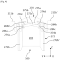
- Anordnung (100) nach einem der Ansprüche 3 bis 5, wobei der erste Körperteil (272) der Befestigungsbasis (270) einen ersten backbordseitigen Vorsprung (274a) und einen ersten steuerbordseitigen Vorsprung (274b) umfasst, die sich in einer zu der vertikalen Mittelebene (XZ) im Wesentlichen senkrechten Ebene vertikal erstrecken, wobei die ersten Vorsprünge (274a, 274b) auf beiden Seiten der Primärstruktur (202) oben an den Seitenplatten (208) angeordnet sind,wobei die Anordnung (100) für den ersten backbordseitigen Vorsprung (274a) eine erste Stange (275a) umfasst, von der ein erstes Ende durch eine zehnte Schwenkverbindung (284a) an dem ersten Vorsprung (274a) befestigt ist,wobei die Anordnung (100) für den ersten steuerbordseitigen Vorsprung (274b) eine zweite Stange (275b) umfasst, von der ein erstes Ende durch eine elfte Schwenkverbindung (284b) an dem ersten steuerbordseitigen Vorsprung (274b) befestigt ist,und dass die zweiten Beschläge, der backbordseitige (211b) und der steuerbordseitige (211b'), einen zweiten backbordseitigen Vorsprung (274c) bzw. einen zweiten steuerbordseitigen Vorsprung (274d) umfassen, die sich in einer zu der vertikalen Mittelebene (XZ) im Wesentlichen senkrechten Ebene vertikal erstrecken, wobei sich die zweiten Vorsprünge (274c, 274d) unten an den zweiten Beschlägen (211b, 211b') erstrecken, wobei der zweite steuerbordseitige Vorsprung (274d) durch eine elfte Schwenkverbindung (284b) an einem zweiten Ende der ersten Stange (275a) befestigt ist und der zweite backbordseitige Vorsprung (274c) durch eine elfte Schwenkverbindung (284b) an einem zweiten Ende der zweiten Stange (275b) befestigt ist.
- Anordnung (100) nach Anspruch 6, wobei die zehnte (284a) und die elfte (284b) Schwenkverbindung eine justierte Verbindungsachse aufweisen und dass mindestens eine der zwölften (284c) und der dreizehnten (284d) Schwenkverbindung ein Spiel aufweist.
- Anordnung (100) nach Anspruch 1, wobei die zweite (283b), vierte (283e), fünfte (283f) und sechste (283g) Verbindung Schwenkverbindungen oder Gelenkverbindungen sind.
- Flugzeug (10), das ein Antriebssystem (102) und eine Anordnung (100) nach einem der Ansprüche 1 bis 8 umfasst, wobei das Antriebssystem (102) an dem Triebwerkspylon (106) befestigt ist.
Applications Claiming Priority (1)
| Application Number | Priority Date | Filing Date | Title |
|---|---|---|---|
| FR2305084A FR3148995A1 (fr) | 2023-05-23 | 2023-05-23 | Ensemble pour un aéronef comportant une aile et un mât réacteur pour coupler un système de propulsion à ladite aile |
Publications (2)
| Publication Number | Publication Date |
|---|---|
| EP4467461A1 EP4467461A1 (de) | 2024-11-27 |
| EP4467461B1 true EP4467461B1 (de) | 2025-07-02 |
Family
ID=87889609
Family Applications (1)
| Application Number | Title | Priority Date | Filing Date |
|---|---|---|---|
| EP24175736.8A Active EP4467461B1 (de) | 2023-05-23 | 2024-05-14 | Anordnung für ein flugzeug mit einem flügel und einem triebwerkmast zur kopplung eines antriebssystems an den flügel |
Country Status (4)
| Country | Link |
|---|---|
| US (1) | US12397899B2 (de) |
| EP (1) | EP4467461B1 (de) |
| CN (1) | CN119018352A (de) |
| FR (1) | FR3148995A1 (de) |
Family Cites Families (5)
| Publication number | Priority date | Publication date | Assignee | Title |
|---|---|---|---|---|
| GB2010969A (en) * | 1977-12-22 | 1979-07-04 | Rolls Royce | Mounting for Gas Turbine Jet Propulsion Engine |
| GB8300748D0 (en) * | 1983-01-12 | 1983-02-16 | British Aerospace | Power plant attachment for aircraft wings |
| US9238511B2 (en) * | 2014-03-04 | 2016-01-19 | Mra Systems, Inc. | Engine pylon structure |
| FR3032180B1 (fr) | 2015-01-30 | 2018-05-18 | Airbus Operations | Ensemble propulsif comportant un turboreacteur et un mat d'accrochage permettant une nouvelle distribution des efforts entre le turboreacteur et la voilure |
| FR3115528A1 (fr) * | 2020-10-27 | 2022-04-29 | Airbus Operations | Architecture de mât haubané pour accrocher un moteur à un aéronef |
-
2023
- 2023-05-23 FR FR2305084A patent/FR3148995A1/fr not_active Ceased
-
2024
- 2024-05-14 EP EP24175736.8A patent/EP4467461B1/de active Active
- 2024-05-21 US US18/670,164 patent/US12397899B2/en active Active
- 2024-05-23 CN CN202410644745.5A patent/CN119018352A/zh active Pending
Also Published As
| Publication number | Publication date |
|---|---|
| US20240391581A1 (en) | 2024-11-28 |
| US12397899B2 (en) | 2025-08-26 |
| CN119018352A (zh) | 2024-11-26 |
| EP4467461A1 (de) | 2024-11-27 |
| FR3148995A1 (fr) | 2024-11-29 |
Similar Documents
| Publication | Publication Date | Title |
|---|---|---|
| EP2137072B1 (de) | Vorrichtung zur befestigung eines flugzeugtriebwerks und flugzeug mit mindestens einer derartigen vorrichtung | |
| EP2038174B1 (de) | Vorrichtung zur triebwerksbefestigung mit zwei schräg zusammenpassenden schubreaktionsverbindungsstangen | |
| FR3068008B1 (fr) | Ensemble de motorisation pour un aeronef | |
| EP3505439B1 (de) | Einheit für ein luftfahrzeug, die eine primärstruktur eines aufhängungsmasts umfasst, die an einem flügelkasten durch befestigungselemente befestigt ist und im vorderkantenbereich ein reduziertes volumen aufweist | |
| EP3505448B1 (de) | Einheit für ein luftfahrzeug, die eine primärstruktur eines aufhängungsmasts umfasst, die an einem flügelkasten mithilfe von anschlüssen reduzierten volumens in der vorderkantenzone befestigt ist | |
| EP3757012B1 (de) | Flugzeugantriebssystem mit verbesserter primärmaststruktur und vorderer triebwerksbefestigung | |
| CA2613194A1 (fr) | Attache moteur pour aeronef destinee a etre interposee entre un moteur et un mat d'accrochage | |
| FR2917713A1 (fr) | Dispositif d'accrochage de moteur d'aeronef et aeronef comportant au moins un tel dispositif. | |
| EP3489147A1 (de) | Einheit für luftfahrzeug, die eine primärstruktur einer aufhängesäule umfasst, die an einem fahrwerkskasten mithilfe von teilweise in der primärstruktur verankerten anschlüssen befestigt ist | |
| FR3041935A1 (fr) | Ensemble moteur pour aeronef comprenant au moins deux attaches moteur arriere decalees axialement l'une de l'autre | |
| EP4368512B1 (de) | Anordnung für ein flugzeug mit einem flügel und einem reaktormast zur kopplung eines antriebssystems an den flügel | |
| EP3521173B1 (de) | Einheit für luftfahrzeug, die eine primärstruktur einer aufhängesäule umfasst, die an einem fahrwerkskasten mithilfe einer verschraubten verbindung befestigt ist | |
| FR3099464A1 (fr) | Mat reacteur pour coupler un turboreacteur a une aile d’un aeronef | |
| WO2006021721A1 (fr) | Ensemble moteur pour aeronef | |
| EP3486174B1 (de) | Hintere motorbefestigung für einen luftfahrzeugmotor | |
| EP4484297B1 (de) | Vordermotorbefestigungssystem für einen flugzeugmotor mit kompakter struktur | |
| EP3992087B1 (de) | Architektur eines abgespannten mastes zum aufhängen eines triebwerks an einem luftfahrzeug | |
| EP3939891B1 (de) | Anordnung für ein luftfahrzeug aus einem flügel und einem triebwerksträger zur ankopplung eines turbotriebwerks an diesen flügel | |
| EP4467461B1 (de) | Anordnung für ein flugzeug mit einem flügel und einem triebwerkmast zur kopplung eines antriebssystems an den flügel | |
| EP3715258A1 (de) | Hintere motorbefestigung eines luftfahrzeugs, die schwingarme aus zwei teilen umfasst, und luftfahrzeug, das mindestens eine solche hintere motorbefestigung umfasst | |
| FR3103788A1 (fr) | Ensemble pour un aeronef, ledit ensemble comportant un mat, une aile et un systeme de fixation entre le mat et l’aile | |
| FR2887522A1 (fr) | Ensemble pour aeronef comprenant un element de voilure ainsi qu'un mat d'accrochage | |
| EP4491518B1 (de) | Flugzeugtriebwerkanordnung mit einer hauptstange zur motorbefestigung, sowie zwei parallel an einer querverstärkung vor einer primärstruktur eines masts | |
| EP3848288B1 (de) | Hintere befestigung zwischen einer aufhängesäule und einer tragfläche eines flugzeugs | |
| EP4516677A1 (de) | Anordnung für ein luftfahrzeug mit einem flügel und einem strahltriebwerk-pylon zur kopplung eines antriebssystems an den flügel |
Legal Events
| Date | Code | Title | Description |
|---|---|---|---|
| PUAI | Public reference made under article 153(3) epc to a published international application that has entered the european phase |
Free format text: ORIGINAL CODE: 0009012 |
|
| STAA | Information on the status of an ep patent application or granted ep patent |
Free format text: STATUS: REQUEST FOR EXAMINATION WAS MADE |
|
| 17P | Request for examination filed |
Effective date: 20240514 |
|
| AK | Designated contracting states |
Kind code of ref document: A1 Designated state(s): AL AT BE BG CH CY CZ DE DK EE ES FI FR GB GR HR HU IE IS IT LI LT LU LV MC ME MK MT NL NO PL PT RO RS SE SI SK SM TR |
|
| GRAP | Despatch of communication of intention to grant a patent |
Free format text: ORIGINAL CODE: EPIDOSNIGR1 |
|
| STAA | Information on the status of an ep patent application or granted ep patent |
Free format text: STATUS: GRANT OF PATENT IS INTENDED |
|
| INTG | Intention to grant announced |
Effective date: 20250326 |
|
| GRAS | Grant fee paid |
Free format text: ORIGINAL CODE: EPIDOSNIGR3 |
|
| GRAA | (expected) grant |
Free format text: ORIGINAL CODE: 0009210 |
|
| STAA | Information on the status of an ep patent application or granted ep patent |
Free format text: STATUS: THE PATENT HAS BEEN GRANTED |
|
| AK | Designated contracting states |
Kind code of ref document: B1 Designated state(s): AL AT BE BG CH CY CZ DE DK EE ES FI FR GB GR HR HU IE IS IT LI LT LU LV MC ME MK MT NL NO PL PT RO RS SE SI SK SM TR |
|
| REG | Reference to a national code |
Ref country code: GB Ref legal event code: FG4D Free format text: NOT ENGLISH |
|
| REG | Reference to a national code |
Ref country code: CH Ref legal event code: EP |
|
| REG | Reference to a national code |
Ref country code: DE Ref legal event code: R096 Ref document number: 602024000267 Country of ref document: DE |
|
| REG | Reference to a national code |
Ref country code: IE Ref legal event code: FG4D Free format text: LANGUAGE OF EP DOCUMENT: FRENCH |
|
| REG | Reference to a national code |
Ref country code: NL Ref legal event code: MP Effective date: 20250702 |
|
| PG25 | Lapsed in a contracting state [announced via postgrant information from national office to epo] |
Ref country code: PT Free format text: LAPSE BECAUSE OF FAILURE TO SUBMIT A TRANSLATION OF THE DESCRIPTION OR TO PAY THE FEE WITHIN THE PRESCRIBED TIME-LIMIT Effective date: 20251103 |
|
| PG25 | Lapsed in a contracting state [announced via postgrant information from national office to epo] |
Ref country code: NL Free format text: LAPSE BECAUSE OF FAILURE TO SUBMIT A TRANSLATION OF THE DESCRIPTION OR TO PAY THE FEE WITHIN THE PRESCRIBED TIME-LIMIT Effective date: 20250702 |
|
| REG | Reference to a national code |
Ref country code: AT Ref legal event code: MK05 Ref document number: 1808992 Country of ref document: AT Kind code of ref document: T Effective date: 20250702 |
|
| PG25 | Lapsed in a contracting state [announced via postgrant information from national office to epo] |
Ref country code: IS Free format text: LAPSE BECAUSE OF FAILURE TO SUBMIT A TRANSLATION OF THE DESCRIPTION OR TO PAY THE FEE WITHIN THE PRESCRIBED TIME-LIMIT Effective date: 20251102 |
|
| PG25 | Lapsed in a contracting state [announced via postgrant information from national office to epo] |
Ref country code: NO Free format text: LAPSE BECAUSE OF FAILURE TO SUBMIT A TRANSLATION OF THE DESCRIPTION OR TO PAY THE FEE WITHIN THE PRESCRIBED TIME-LIMIT Effective date: 20251002 |
|
| REG | Reference to a national code |
Ref country code: LT Ref legal event code: MG9D |
|
| PG25 | Lapsed in a contracting state [announced via postgrant information from national office to epo] |
Ref country code: AT Free format text: LAPSE BECAUSE OF FAILURE TO SUBMIT A TRANSLATION OF THE DESCRIPTION OR TO PAY THE FEE WITHIN THE PRESCRIBED TIME-LIMIT Effective date: 20250702 |
|
| PG25 | Lapsed in a contracting state [announced via postgrant information from national office to epo] |
Ref country code: FI Free format text: LAPSE BECAUSE OF FAILURE TO SUBMIT A TRANSLATION OF THE DESCRIPTION OR TO PAY THE FEE WITHIN THE PRESCRIBED TIME-LIMIT Effective date: 20250702 |
|
| PG25 | Lapsed in a contracting state [announced via postgrant information from national office to epo] |
Ref country code: HR Free format text: LAPSE BECAUSE OF FAILURE TO SUBMIT A TRANSLATION OF THE DESCRIPTION OR TO PAY THE FEE WITHIN THE PRESCRIBED TIME-LIMIT Effective date: 20250702 |
|
| PG25 | Lapsed in a contracting state [announced via postgrant information from national office to epo] |
Ref country code: GR Free format text: LAPSE BECAUSE OF FAILURE TO SUBMIT A TRANSLATION OF THE DESCRIPTION OR TO PAY THE FEE WITHIN THE PRESCRIBED TIME-LIMIT Effective date: 20251003 |
|
| PG25 | Lapsed in a contracting state [announced via postgrant information from national office to epo] |
Ref country code: SE Free format text: LAPSE BECAUSE OF FAILURE TO SUBMIT A TRANSLATION OF THE DESCRIPTION OR TO PAY THE FEE WITHIN THE PRESCRIBED TIME-LIMIT Effective date: 20250702 Ref country code: CZ Free format text: LAPSE BECAUSE OF FAILURE TO SUBMIT A TRANSLATION OF THE DESCRIPTION OR TO PAY THE FEE WITHIN THE PRESCRIBED TIME-LIMIT Effective date: 20250702 |
|
| PG25 | Lapsed in a contracting state [announced via postgrant information from national office to epo] |
Ref country code: LV Free format text: LAPSE BECAUSE OF FAILURE TO SUBMIT A TRANSLATION OF THE DESCRIPTION OR TO PAY THE FEE WITHIN THE PRESCRIBED TIME-LIMIT Effective date: 20250702 |
|
| PG25 | Lapsed in a contracting state [announced via postgrant information from national office to epo] |
Ref country code: PL Free format text: LAPSE BECAUSE OF FAILURE TO SUBMIT A TRANSLATION OF THE DESCRIPTION OR TO PAY THE FEE WITHIN THE PRESCRIBED TIME-LIMIT Effective date: 20250702 Ref country code: BG Free format text: LAPSE BECAUSE OF FAILURE TO SUBMIT A TRANSLATION OF THE DESCRIPTION OR TO PAY THE FEE WITHIN THE PRESCRIBED TIME-LIMIT Effective date: 20250702 |
|
| PG25 | Lapsed in a contracting state [announced via postgrant information from national office to epo] |
Ref country code: RS Free format text: LAPSE BECAUSE OF FAILURE TO SUBMIT A TRANSLATION OF THE DESCRIPTION OR TO PAY THE FEE WITHIN THE PRESCRIBED TIME-LIMIT Effective date: 20251002 |
|
| PG25 | Lapsed in a contracting state [announced via postgrant information from national office to epo] |
Ref country code: ES Free format text: LAPSE BECAUSE OF FAILURE TO SUBMIT A TRANSLATION OF THE DESCRIPTION OR TO PAY THE FEE WITHIN THE PRESCRIBED TIME-LIMIT Effective date: 20250702 |
|
| PG25 | Lapsed in a contracting state [announced via postgrant information from national office to epo] |
Ref country code: SM Free format text: LAPSE BECAUSE OF FAILURE TO SUBMIT A TRANSLATION OF THE DESCRIPTION OR TO PAY THE FEE WITHIN THE PRESCRIBED TIME-LIMIT Effective date: 20250702 |
|
| PG25 | Lapsed in a contracting state [announced via postgrant information from national office to epo] |
Ref country code: DK Free format text: LAPSE BECAUSE OF FAILURE TO SUBMIT A TRANSLATION OF THE DESCRIPTION OR TO PAY THE FEE WITHIN THE PRESCRIBED TIME-LIMIT Effective date: 20250702 |
|
| PG25 | Lapsed in a contracting state [announced via postgrant information from national office to epo] |
Ref country code: IT Free format text: LAPSE BECAUSE OF FAILURE TO SUBMIT A TRANSLATION OF THE DESCRIPTION OR TO PAY THE FEE WITHIN THE PRESCRIBED TIME-LIMIT Effective date: 20250702 |