EP4467461A1 - Anordnung für ein flugzeug mit einem flügel und einem triebwerkmast zur kopplung eines antriebssystems an den flügel - Google Patents
Anordnung für ein flugzeug mit einem flügel und einem triebwerkmast zur kopplung eines antriebssystems an den flügel Download PDFInfo
- Publication number
- EP4467461A1 EP4467461A1 EP24175736.8A EP24175736A EP4467461A1 EP 4467461 A1 EP4467461 A1 EP 4467461A1 EP 24175736 A EP24175736 A EP 24175736A EP 4467461 A1 EP4467461 A1 EP 4467461A1
- Authority
- EP
- European Patent Office
- Prior art keywords
- fixed
- fixing
- starboard
- assembly
- connection
- Prior art date
- Legal status (The legal status is an assumption and is not a legal conclusion. Google has not performed a legal analysis and makes no representation as to the accuracy of the status listed.)
- Granted
Links
Images

Classifications
-
- B—PERFORMING OPERATIONS; TRANSPORTING
- B64—AIRCRAFT; AVIATION; COSMONAUTICS
- B64D—EQUIPMENT FOR FITTING IN OR TO AIRCRAFT; FLIGHT SUITS; PARACHUTES; ARRANGEMENT OR MOUNTING OF POWER PLANTS OR PROPULSION TRANSMISSIONS IN AIRCRAFT
- B64D27/00—Arrangement or mounting of power plants in aircraft; Aircraft characterised by the type or position of power plants
- B64D27/02—Aircraft characterised by the type or position of power plants
- B64D27/10—Aircraft characterised by the type or position of power plants of gas-turbine type
- B64D27/12—Aircraft characterised by the type or position of power plants of gas-turbine type within, or attached to, wings
-
- B—PERFORMING OPERATIONS; TRANSPORTING
- B64—AIRCRAFT; AVIATION; COSMONAUTICS
- B64C—AEROPLANES; HELICOPTERS
- B64C3/00—Wings
- B64C3/32—Wings specially adapted for mounting power plant
-
- B—PERFORMING OPERATIONS; TRANSPORTING
- B64—AIRCRAFT; AVIATION; COSMONAUTICS
- B64D—EQUIPMENT FOR FITTING IN OR TO AIRCRAFT; FLIGHT SUITS; PARACHUTES; ARRANGEMENT OR MOUNTING OF POWER PLANTS OR PROPULSION TRANSMISSIONS IN AIRCRAFT
- B64D27/00—Arrangement or mounting of power plants in aircraft; Aircraft characterised by the type or position of power plants
- B64D27/02—Aircraft characterised by the type or position of power plants
- B64D27/16—Aircraft characterised by the type or position of power plants of jet type
- B64D27/18—Aircraft characterised by the type or position of power plants of jet type within, or attached to, wings
-
- B—PERFORMING OPERATIONS; TRANSPORTING
- B64—AIRCRAFT; AVIATION; COSMONAUTICS
- B64D—EQUIPMENT FOR FITTING IN OR TO AIRCRAFT; FLIGHT SUITS; PARACHUTES; ARRANGEMENT OR MOUNTING OF POWER PLANTS OR PROPULSION TRANSMISSIONS IN AIRCRAFT
- B64D27/00—Arrangement or mounting of power plants in aircraft; Aircraft characterised by the type or position of power plants
- B64D27/40—Arrangements for mounting power plants in aircraft
- B64D27/402—Arrangements for mounting power plants in aircraft comprising box like supporting frames, e.g. pylons or arrangements for embracing the power plant
-
- B—PERFORMING OPERATIONS; TRANSPORTING
- B64—AIRCRAFT; AVIATION; COSMONAUTICS
- B64D—EQUIPMENT FOR FITTING IN OR TO AIRCRAFT; FLIGHT SUITS; PARACHUTES; ARRANGEMENT OR MOUNTING OF POWER PLANTS OR PROPULSION TRANSMISSIONS IN AIRCRAFT
- B64D27/00—Arrangement or mounting of power plants in aircraft; Aircraft characterised by the type or position of power plants
- B64D27/40—Arrangements for mounting power plants in aircraft
- B64D27/404—Suspension arrangements specially adapted for supporting vertical loads
Definitions
- the present invention relates to an assembly for an aircraft comprising a wing and a power plant for coupling a propulsion system to the wing, as well as to an aircraft comprising a propulsion system and such an assembly for coupling the propulsion system to the wing.
- a propulsion system typically includes, for example, a turbojet engine that is attached to a wing of the aircraft using a jet engine pylon.
- the jet engine pylon is typically made up of a primary structure formed by a box consisting of an upper spar, a lower spar, and two side panels connecting the two spars, and internal ribs distributed along the box.
- the turbojet engine is fixed under the engine pylon to the engine attachment means which conventionally comprise, at the front, a front engine attachment, at the rear, a rear engine attachment, and between the front and rear engine attachments, a thrust force recovery assembly comprising recovery rods fixed between the turbojet engine and the primary structure of the pylon, to absorb the thrust forces generated by the turbojet engine.
- the engine pylon is further attached to the wing structure using a mounting base. More specifically, the mounting base has a substantially inverted U shape and is intended to receive the rear end of the box. The base also carries the attachments of the engine pylon to secure the latter to the wing structure using fittings through which the forces from the turbojet are transmitted to the wing structure.
- turbojets Although current installations are satisfactory, the size of turbojets is increasing but it is not preferable to modify the dimensions of the landing gear so as to modify the height of the wing relative to the ground for reasons of weight and size penalties.
- the box has relatively large dimensions which make it difficult to position the turbojet under the wing.
- An object of the present invention is to propose an assembly for an aircraft comprising a wing and a reactor mast for coupling a propulsion system to the wing and which comprises means of attachment to the wing which make it possible to reduce the size of the reactor mast while ensuring an optimized transfer of forces to the structure of the wing.
- Said body comprises two first starboard and port fixing clevises extending to the rear and in the upper part on the sides of said fixing base, each of said first fixing clevises being fixed to one of said second fittings by a first pivot connection.
- Said body also comprises two second starboard and port fixing yokes extending to the rear and in the lower part on the sides of said fixing base, each of said two second fixing yokes being fixed by a second connection to a second end respectively of the first and second connecting rods.
- Said second connection has at least one degree of freedom in rotation.
- Said body further comprises at least a third central fixing yoke extending to the rear and at the level of the vertical median plane, said third central fixing yoke being fixed to a second end of said third connecting rod by a sixth connection, said sixth connection having at least one degree of freedom in rotation.
- the assembly comprises a fourth starboard fitting and a fourth port fitting, each of said fourth fittings being fixed to the primary structure of the engine pylon.
- the assembly comprises a fourth connecting rod, a first end of which is fixed to said fourth fitting by an eighth pivot connection.
- said body comprises two fourth starboard and port fixing clevises extending at the front and in the lower part on the sides of said fixing base, each of said fourth fixing clevises being fixed to a second end of a fourth connecting rod by a ninth pivot connection.
- the engine forces that are transported by the primary structure of the mast are transmitted directly to the extrados and intrados panels via the fixing base.
- the implementation of the fourth connecting rods connecting the primary structure of the reactor mast to the fixing base makes it possible to reduce the dimensions of the primary structure of the reactor mast, thus allowing and facilitating the fixing of turbojets of larger dimensions to the wing of the aircraft.
- said primary structure comprises an upper spar, a lower spar and two starboard and port side panels connecting the two spars, said fourth fittings being fixed on either side of said primary structure in the lower part of said side panels.
- said body comprises a first inverted U-shaped body part extending inside a second inverted U-shaped body part, where the rear part of the primary structure is fixed in the first body part, and where the two first fixing yokes, the two second fixing yokes and the two fourth fixing yokes are integral with the second body part.
- said first body part extends inside said second body part, said first body part and said second body part extending in the same plane, parallel to the vertical plane.
- said body comprises at least one reinforcing rib connecting said first body part and said second body part.
- said rear part of the primary structure integral with said fixing base has a height measured in the vertical direction between said upper and lower side members and a width measured in the transverse direction between said side panels
- said fixing base has a height measured between the orthogonal projection of an axis of a second connection of said second fixing yoke and an axis of a sixth connection of said third fixing yoke and a width measured in the transverse direction between said two first fixing yokes, the height of said primary structure being less than the height of said fixing base and the width of said primary structure being less than the width of said fixing base.
- said first body part of said fixing base comprises a first port protrusion and a first starboard protrusion extending vertically in a plane generally perpendicular to the vertical median plane, said first protrusions being arranged on either side of said primary structure in the upper part of said side panels.
- the assembly comprises a first connecting rod, a first end of which is fixed to said first protrusion by a tenth pivot connection.
- the assembly comprises a second connecting rod, a first end of which is fixed to said first starboard protrusion by an eleventh pivot connection.
- Said second port and starboard fittings respectively comprise a second port protrusion and a second starboard protrusion extending vertically in a plane generally perpendicular to the vertical median plane, said second protrusions extending in the lower part of the second fittings, the second starboard protrusion being fixed to a second end of said first connecting rod by an eleventh pivot connection and said second port protrusion being fixed to a second end of said second connecting rod by an eleventh pivot connection.
- said tenth and eleventh pivot links have an adjusted connection axis and at least one of said twelfth and thirteenth pivot links has a connection axis comprising play.
- said second, fourth, fifth and sixth links are pivot links or ball joints.
- the invention also provides an aircraft comprising a propulsion system and an assembly as described above, where the propulsion system is attached to the engine pylon.
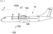
- FIG. 1 shows an aircraft 10 which comprises a propulsion system 102, for example of the turbojet or turboprop type.
- the propulsion system 102 is linked to a wing 104 of the aircraft 10 by means of a reactor mast 106.
- the wing 104 and the reactor mast 106 form an assembly 100 according to the invention and the propulsion system 102 is fixed to the reactor mast 106 by any suitable fixing means known to those skilled in the art such as those disclosed in the document US-A-2016/0221682 .
- X the longitudinal direction of the propulsion system which is horizontal when the aircraft is on the ground
- Y the transverse direction which is horizontal when the aircraft is on the ground
- Z the vertical direction which is vertical when the aircraft is on the ground
- the reactor mast 106 and the propulsion system 102 have a vertical median plane XZ and the propulsion system 102 is here a turboprop with a propeller 102a, but it could be of the double-flow turbojet type with a nacelle.
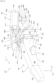
- FIG. 2 shows the assembly 100 according to the invention.
- the reactor mast 106 comprises a rigid structure forming a box and also called primary structure 202.
- the primary structure 202 is formed of an upper spar 204, a lower spar 206 and two side panels 208 (only the port panel is shown in the Figs. 2 And 3 ) starboard and port connecting the two longerons 204 and 206.
- the shape of the primary structure 202 is in this example configured so that the reactor mast 106 has a front pyramid 201, located at the front end of the reactor mast 106 in the direction of advancement F, and a base 203, substantially rectangular, located at the rear end of the reactor mast 106 in the direction of advancement F.
- the base 203 has a height h measured substantially in the vertical direction Z between the upper 204 and lower 206 side members and a width 1 measured substantially in the transverse direction Y between the two side panels 208.
- the wing structure 104 includes a front spar 210, an upper surface panel 214 and a lower surface panel 216 which are both attached to the front spar 210 and extend generally in horizontal planes XY.
- its structure includes other elements such as ribs which are distributed between the extrados panel 214 and the intrados panel 216.
- the front spar 210 here takes the form of a profile in the shape of an inverted Z step on the Figs. 2 And 3 , with an upper wing 210a (also called a top portion) and a lower wing 210b (also called a bottom portion) that are generally horizontal and a central portion 210c generally perpendicular to the median plane and extending generally vertically parallel to the YZ plane.
- the extrados panel 214 is attached above the upper wing 210a of the spar 210 and the intrados panel 216 is attached below the lower wing 210b of the spar 210.
- the attachment of the front spar 210 to the panels 214 and 216 is achieved by any suitable means such as welds, bolts, etc.
- the extrados panel 214 is thus fixed in the upper part of the front spar 210 and the intrados panel 216 is fixed in the lower part of the front spar 210.
- the central part 210c is at the level of the leading edge of the wing 104.
- the front spar 210 carries a first fitting 211a fixed at the level of the vertical median plane XZ and more particularly here at the central part 210c of the front spar 210.
- the intrados panel 216 carries two second fittings, starboard 211b' and port 211b (only the second port fitting is shown in the drawings). Figs. 2 And 3 , the second starboard fitting is shown in the Fig. 4 ) which are fixed on the external face of the intrados panel 216 and in alignment with the lower part 210b of the front spar 210.
- the intrados panel 216 also carries a third fitting 221 (visible in the Fig.
- the third fitting 221 is positioned at the rear of the second starboard 211b' and port 211b fittings.
- the assembly 100 further comprises a fixing base 270 secured to the rear part of the primary structure 202.
- the fixing base 270 comprises in this example a body 270a extending vertically in the YZ plane. More precisely, the body 270a has a first body part 272 in the form of an inverted U as well as a second body part 271 also having the shape of an inverted U.
- the first body part 272 and the second body part 271 extend in a vertical plane parallel to the vertical plane YZ and the first body part 272 is arranged inside the second body part 271.
- the first body portion 272 has a central upper wall 272a extending horizontally in a plane parallel to the XY plane.
- the first body portion 272 also has two starboard 272b' and port 272b side walls (only the port side wall is shown in the Figs. 2 And 3 , the starboard side wall is visible on the Fig. 4 ) which extend perpendicularly from the central upper wall 272a and which extend vertically in planes parallel to the vertical median plane XZ.
- the central upper wall 272a and the starboard 272b' and port 272b side walls are integral and extend around and above the rear portion of the primary structure 202 and form a housing 273 for receiving the base 203 of the primary structure 202.
- the dimensions of the housing 273 are obviously chosen to correspond to the dimensions of the base 203 of the primary structure 202. It is understood that the primary structure 202 is fixed to the housing 273 by any suitable means such as welds, bolts, etc.
- the fixing base 270 comprises at least one reinforcing rib 272c connecting the walls 272a, 272b, 272b' of the first body part 272 to the second body part 271. In this example, three ribs 272c are used (only two ribs are visible on the Fig. 2 ) and extend respectively from the upper central wall 272a and the starboard 272b' and port 272b side walls to the second body part 271.
- These reinforcing ribs 272c in particular allow the fixing base 270 to support and transmit the forces coming from the propulsion system 102 to the wing 104.
- the ribs 272c fix together the walls 272a, 272b, 272b' of the first body part 272 to the walls of the second body part 271.
- the second body part 271 of the body 270a of the attachment base 270 comprises two first starboard and port attachment clevises 273a (only the first port attachment clevis is shown in the drawings).
- Figs. 2 And 3 which extend from the second body part 271 of the body 270a towards the rear and which are arranged in the upper part on the sides of the fixing base 270.
- Each of the first fixing yokes 273a is secured to one of the second fittings 211b, 211b' by a first pivot connection 283a, in particular a sliding pivot connection.
- first fixing clevises 273a and the second fittings 211b, 211b' each comprise a bore into which an axle is threaded to form the first pivot connection 283a.
- This first pivot connection 283a has a substantially horizontal axis of rotation which extends generally parallel to the transverse direction Y.
- the second body part 271 of the body 270a of the fixing base 270 also comprises two second starboard and port fixing yokes 273b (only the second port fixing yoke is shown in the Figs. 2 And 3 ) which extend from the second body part 271 of the body 270a towards the rear and which are arranged in the lower part on the sides of the fixing base 270.
- the two second fixing yokes 273b are integral with a shackle 280 which can be triangular, respectively by a first and a second connecting rod 281a, 281b.
- the second starboard fixing yoke is fixed to a second end of the first connecting rod 281a by means of a second connection 283b, while the second port fixing yoke 273b is fixed to a second end of the second connecting rod 281b by means of another second connection 283b.
- the second connection 283b has at least one degree of freedom in rotation about an axis extending here substantially parallel to the transverse direction Y.
- the second connection 283b is a pivot connection whose axis extends generally parallel to the transverse direction Y.
- the first ends of the first 281a and second 281b connecting rods are respectively fixed to the shackle 280 by a third 283c and a fourth 283d pivot links.
- the axis of the third 283c and fourth 283d pivot links extends generally parallel to the direction perpendicular to the plane passing through the axes of the first and second connecting rods 281a, 281b.
- the first ends of each two second connecting rods 281a, 281b and the shackle 280 comprise bores in which pins are threaded to form said third 283c and fourth 283d pivot links.
- the shackle 280 is fixed by a fifth connection 283e to the third fitting 221 of the intrados 216.
- the fifth connection 283e has at least one degree of freedom in rotation along an axis extending here substantially parallel to the vertical direction Z.
- the fifth connection 283e is a pivot connection whose axis extends generally parallel to the direction perpendicular to the plane passing through the axes of the first and second connecting rods 281a, 281b.
- the shackle 280 and the third fitting 221 each have a bore into which an axis is threaded to form the fifth pivot connection 283e.
- the second body portion 271 of the body 270a of the fixing base 270 also comprises at least one third central fixing yoke 273c (only one in the illustrated example) which extends from the second body portion 271 of the body 270a towards the rear and which is arranged substantially in a centered manner (i.e. at the level of the vertical median plane XZ) in the upper part of the fixing base 270.
- the third central fixing yoke 273c is fixed to the first fitting 211a by a third connecting rod 282. More precisely, a first end of the third connecting rod 282 is fixed to the first fitting 211a by a seventh connection 283g and the second end of the third connecting rod 282 is fixed to the third central fixing yoke 273c by a sixth connection 283f.
- the sixth 283f and seventh 283g connections have at least one degree of freedom in rotation about an axis extending here substantially parallel to the transverse direction Y.
- the sixth 283f and seventh 283g connections are pivot connections whose axis extends generally parallel to the transverse direction Y.
- the third connecting rod 282 has a bore at each of its ends in each of which an axle is threaded and cooperates respectively with a bore made in the third central fixing yoke 273c and in the first fitting 211a to form the sixth 283f and seventh 283g pivot connections.
- the primary structure 202 carries a fourth starboard fitting and a fourth port fitting 301 (only the fourth port fitting is visible in the Figs. 2 And 3 ).
- the fourth fittings 301 are fixed on either side of the primary structure 202.
- the fourth starboard fitting is fixed to the starboard side panel and the fourth port fitting 301 is fixed to the port side panel 208.
- the fourth fittings 301 are fixed in the lower part of the side panels 208 so as to optimize the transmission of forces coming from the propulsion system 102 and passing through the reactor mast 106 towards the wing 104.
- the second body portion 271 of the body 270a of the fixing base 270 further comprises two fourth starboard and port fixing yokes 302 extending at the front and in the upper part on the sides of said fixing base 270.
- Each of the fourth fixing yokes 302 is fixed to a second end of a fourth connecting rod 303 by a ninth pivot connection 305.
- the second end of each fourth connecting rod 303 is fixed to a fourth fitting 201 by an eighth pivot connection 304.
- the axis of the eighth 304 and ninth 305 pivot links is generally parallel to the transverse direction Y.
- the implementation of the fourth fittings 301, the fourth fixing yokes 302 and the fourth connecting rods 303 makes it possible to reduce the dimensions of the primary structure 202 of the engine pylon 106 while ensuring an optimized transfer of the forces coming from the propulsion system 102 to the structure of the wing 104 thanks to these additional force paths. Consequently, the reduction in the dimensions of the primary structure 202 of the engine pylon 106 allows and facilitates the installation and fixing of propulsion systems of dimensions larger than the turbojets currently fixed to the wing of the aircraft.
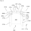
- the assembly 100 further comprises a set of two connecting rods 275a, 275b making it possible to react to the forces coming from the propulsion system 102 essentially in the transverse direction Y.
- the fixing base 270 comprises, at the level of the first body part 272, a first port protrusion 274a and a first starboard protrusion 274b.
- each first protrusion 274a, 274b has an ear shape and extends vertically and perpendicularly to the side walls 272b, 272b', that is to say in a plane perpendicular to the vertical median plane XZ.
- first port protrusion 274a extends substantially in the corner between the central upper wall 272a and the port side panel 208 of the primary structure 202 and the first starboard protrusion 274b extends substantially in the corner between the central upper wall 272a and the starboard side panel 208 of the primary structure 202.
- the first protrusions 274a, 274b are arranged in the upper part and in the rear part of the fixing base 270, that is to say at the rear of the primary structure 202.
- the second port fittings 211b and starboard fittings 211b' respectively carry a second port protrusion 274c and a second starboard protrusion 274d.
- each second protrusion 274c, 274d also has an ear shape and extends vertically in a plane perpendicular to the vertical median plane XZ.
- the second protrusions 274c, 274d extend in the lower part of the second fittings 211b, 211b'.
- first protrusions 274a and 274b face each other.
- second protrusions 274c and 274d also face each other.
- the set of connecting rods 275a, 275b crosswise connects the second fittings 211b, 211b' to the base. fixing 270. More precisely, a first connecting rod 275a connects the first port protrusion 274a to the second starboard protrusion 274d while the second connecting rod 275b connects the first starboard protrusion 274b to the second port protrusion 274c.
- the first 275a and second 275b connecting rods are therefore crossed and extend substantially in two parallel planes perpendicular to the vertical median plane XZ. The two parallel planes are slightly spaced apart to promote the crossing of the first 275a and second 275b connecting rods.
- first connecting rod 275a The ends of the first connecting rod 275a are secured to the first port outgrowth 274a and to the second starboard outgrowth 274d respectively by a tenth 284a and an eleventh 284b pivot connection.
- the ends of the second connecting rod 275b are secured to the first starboard outgrowth 274b and to the second port outgrowth 274c respectively by a twelfth 284c and a thirteenth 284d pivot connection.
- first connecting rod 275a is said to be “engaged” while the second connecting rod 275b is said to be “on standby”.
- first connecting rod 275a represents the so-called “main” force path for the transmission of forces having a component substantially oriented in the transverse direction Y.
- At least one of the twelfth 284c and thirteenth 284d pivot connections has a clearance which allows, in the event of breakage of the first connecting rod 275a, to engage the second connecting rod 275b so that it is the second connecting rod 275b which reacts to the forces having a component substantially oriented in the transverse direction Y.
- the second connecting rod 275b thus represents the so-called “secondary” force path.
- the twelfth 284c and thirteenth 284d pivot connections each have a connecting pin carried respectively by the first starboard protrusion 274b and by the second port protrusion 274c.
- At least one of the bores provided at the ends of the second connecting rod 275b and cooperating with these connecting pins has, for example, an oblong shape such that the second connecting rod 275b is mounted with play at at least one of the twelfth 284c and thirteenth 284d pivot connections.
- the particular implementation of this set of connecting rods 275a, 275b further allows the dimensions of the primary structure 202 of the engine pylon 106 to be reduced while ensuring an optimized transfer of the forces coming from the propulsion system 102 to the structure of the wing 104.
- the fixing base 270 has a height H which is measured between the orthogonal projection of the axis of the second fixing yoke 273b and the axis of the third fixing yoke 273b.
- fixing 273c i.e. vertically in the vertical direction Z
- the width L is measured horizontally (i.e. in the transverse direction Y) between the first two fixing yokes 273a.
- the height h of the primary structure 202 is less than the height H of the fixing base 270 and the width 1 of the primary structure 202 is less than the width L of the fixing base 270.
- the drainage of the forces passing through the primary structure 202 towards the fixing base 270 and the associated connecting rods/shackles is optimized.
- the implementation of a width L of the fixing base 270 greater than the width 1 of the primary structure 202 promotes the recovery of the moment around the vertical axis Z.
- the height H of the fixing base 270 being greater than the height h of the primary structure 202, the points governing the moments around the lateral axis Y are further apart.
- the primary structure 202 has standard dimensions at the level of the front pyramid 201 of the primary structure 202 so as to ensure the compatibility of the assembly 100 with the fixing of propulsion systems currently implemented.
Landscapes
- Engineering & Computer Science (AREA)
- Aviation & Aerospace Engineering (AREA)
- Mechanical Engineering (AREA)
- Pivots And Pivotal Connections (AREA)
- Mutual Connection Of Rods And Tubes (AREA)
- Jib Cranes (AREA)
- Connection Of Plates (AREA)
Applications Claiming Priority (1)
| Application Number | Priority Date | Filing Date | Title |
|---|---|---|---|
| FR2305084A FR3148995A1 (fr) | 2023-05-23 | 2023-05-23 | Ensemble pour un aéronef comportant une aile et un mât réacteur pour coupler un système de propulsion à ladite aile |
Publications (2)
| Publication Number | Publication Date |
|---|---|
| EP4467461A1 true EP4467461A1 (de) | 2024-11-27 |
| EP4467461B1 EP4467461B1 (de) | 2025-07-02 |
Family
ID=87889609
Family Applications (1)
| Application Number | Title | Priority Date | Filing Date |
|---|---|---|---|
| EP24175736.8A Active EP4467461B1 (de) | 2023-05-23 | 2024-05-14 | Anordnung für ein flugzeug mit einem flügel und einem triebwerkmast zur kopplung eines antriebssystems an den flügel |
Country Status (4)
| Country | Link |
|---|---|
| US (1) | US12397899B2 (de) |
| EP (1) | EP4467461B1 (de) |
| CN (1) | CN119018352A (de) |
| FR (1) | FR3148995A1 (de) |
Citations (5)
| Publication number | Priority date | Publication date | Assignee | Title |
|---|---|---|---|---|
| GB2010969A (en) * | 1977-12-22 | 1979-07-04 | Rolls Royce | Mounting for Gas Turbine Jet Propulsion Engine |
| EP0115914B1 (de) * | 1983-01-12 | 1987-01-14 | British Aerospace Public Limited Company | Anordnung der Triebwerksbefestigungen für Flugzeugtragflügel |
| US20150251768A1 (en) * | 2014-03-04 | 2015-09-10 | Mra Systems, Inc. | Engine pylon structure |
| US20160221682A1 (en) | 2015-01-30 | 2016-08-04 | Airbus Operations Sas | Propulsion assembly incorporating a turbojet and a mounting pylon enabling a new distribution of the forces between the turbojet and the wing |
| EP3992087A1 (de) * | 2020-10-27 | 2022-05-04 | Airbus Operations (S.A.S.) | Architektur eines abgespannten mastes zum aufhängen eines triebwerks an einem luftfahrzeug |
-
2023
- 2023-05-23 FR FR2305084A patent/FR3148995A1/fr not_active Ceased
-
2024
- 2024-05-14 EP EP24175736.8A patent/EP4467461B1/de active Active
- 2024-05-21 US US18/670,164 patent/US12397899B2/en active Active
- 2024-05-23 CN CN202410644745.5A patent/CN119018352A/zh active Pending
Patent Citations (5)
| Publication number | Priority date | Publication date | Assignee | Title |
|---|---|---|---|---|
| GB2010969A (en) * | 1977-12-22 | 1979-07-04 | Rolls Royce | Mounting for Gas Turbine Jet Propulsion Engine |
| EP0115914B1 (de) * | 1983-01-12 | 1987-01-14 | British Aerospace Public Limited Company | Anordnung der Triebwerksbefestigungen für Flugzeugtragflügel |
| US20150251768A1 (en) * | 2014-03-04 | 2015-09-10 | Mra Systems, Inc. | Engine pylon structure |
| US20160221682A1 (en) | 2015-01-30 | 2016-08-04 | Airbus Operations Sas | Propulsion assembly incorporating a turbojet and a mounting pylon enabling a new distribution of the forces between the turbojet and the wing |
| EP3992087A1 (de) * | 2020-10-27 | 2022-05-04 | Airbus Operations (S.A.S.) | Architektur eines abgespannten mastes zum aufhängen eines triebwerks an einem luftfahrzeug |
Also Published As
| Publication number | Publication date |
|---|---|
| US20240391581A1 (en) | 2024-11-28 |
| US12397899B2 (en) | 2025-08-26 |
| CN119018352A (zh) | 2024-11-26 |
| EP4467461B1 (de) | 2025-07-02 |
| FR3148995A1 (fr) | 2024-11-29 |
Similar Documents
| Publication | Publication Date | Title |
|---|---|---|
| EP2137072B1 (de) | Vorrichtung zur befestigung eines flugzeugtriebwerks und flugzeug mit mindestens einer derartigen vorrichtung | |
| EP2038174B1 (de) | Vorrichtung zur triebwerksbefestigung mit zwei schräg zusammenpassenden schubreaktionsverbindungsstangen | |
| EP3505439B1 (de) | Einheit für ein luftfahrzeug, die eine primärstruktur eines aufhängungsmasts umfasst, die an einem flügelkasten durch befestigungselemente befestigt ist und im vorderkantenbereich ein reduziertes volumen aufweist | |
| FR3068008B1 (fr) | Ensemble de motorisation pour un aeronef | |
| EP3505448B1 (de) | Einheit für ein luftfahrzeug, die eine primärstruktur eines aufhängungsmasts umfasst, die an einem flügelkasten mithilfe von anschlüssen reduzierten volumens in der vorderkantenzone befestigt ist | |
| WO2008155386A1 (fr) | Dispositif d'accrochage de moteur d'aeronef et procede de montage d'un moteur d'aeronef au moyen d'un tel dispositif | |
| CA2613194A1 (fr) | Attache moteur pour aeronef destinee a etre interposee entre un moteur et un mat d'accrochage | |
| EP1773660B1 (de) | Flugzeugmotoreinheit | |
| EP3489147A1 (de) | Einheit für luftfahrzeug, die eine primärstruktur einer aufhängesäule umfasst, die an einem fahrwerkskasten mithilfe von teilweise in der primärstruktur verankerten anschlüssen befestigt ist | |
| EP4368512B1 (de) | Anordnung für ein flugzeug mit einem flügel und einem reaktormast zur kopplung eines antriebssystems an den flügel | |
| EP4484297B1 (de) | Vordermotorbefestigungssystem für einen flugzeugmotor mit kompakter struktur | |
| EP3521173B1 (de) | Einheit für luftfahrzeug, die eine primärstruktur einer aufhängesäule umfasst, die an einem fahrwerkskasten mithilfe einer verschraubten verbindung befestigt ist | |
| FR3099464A1 (fr) | Mat reacteur pour coupler un turboreacteur a une aile d’un aeronef | |
| FR3096028A1 (fr) | Attache moteur arriere pour un moteur d’aeronef | |
| EP3992087B1 (de) | Architektur eines abgespannten mastes zum aufhängen eines triebwerks an einem luftfahrzeug | |
| EP3939891B1 (de) | Anordnung für ein luftfahrzeug aus einem flügel und einem triebwerksträger zur ankopplung eines turbotriebwerks an diesen flügel | |
| FR3102151A1 (fr) | Aéronef comprenant une attache voilure arrière présentant au moins deux bielles latérales et un pion de cisaillement | |
| EP4467461B1 (de) | Anordnung für ein flugzeug mit einem flügel und einem triebwerkmast zur kopplung eines antriebssystems an den flügel | |
| FR3103788A1 (fr) | Ensemble pour un aeronef, ledit ensemble comportant un mat, une aile et un systeme de fixation entre le mat et l’aile | |
| EP3715258A1 (de) | Hintere motorbefestigung eines luftfahrzeugs, die schwingarme aus zwei teilen umfasst, und luftfahrzeug, das mindestens eine solche hintere motorbefestigung umfasst | |
| EP4491518B1 (de) | Flugzeugtriebwerkanordnung mit einer hauptstange zur motorbefestigung, sowie zwei parallel an einer querverstärkung vor einer primärstruktur eines masts | |
| FR2887522A1 (fr) | Ensemble pour aeronef comprenant un element de voilure ainsi qu'un mat d'accrochage | |
| EP4484298B1 (de) | Vordermotorbefestigungssystem für einen flugzeugmotor mit kompakter struktur | |
| EP4516677A1 (de) | Anordnung für ein luftfahrzeug mit einem flügel und einem strahltriebwerk-pylon zur kopplung eines antriebssystems an den flügel | |
| EP4442577B1 (de) | Reaktormast zur befestigung eines flugzeugmotors |
Legal Events
| Date | Code | Title | Description |
|---|---|---|---|
| PUAI | Public reference made under article 153(3) epc to a published international application that has entered the european phase |
Free format text: ORIGINAL CODE: 0009012 |
|
| STAA | Information on the status of an ep patent application or granted ep patent |
Free format text: STATUS: REQUEST FOR EXAMINATION WAS MADE |
|
| 17P | Request for examination filed |
Effective date: 20240514 |
|
| AK | Designated contracting states |
Kind code of ref document: A1 Designated state(s): AL AT BE BG CH CY CZ DE DK EE ES FI FR GB GR HR HU IE IS IT LI LT LU LV MC ME MK MT NL NO PL PT RO RS SE SI SK SM TR |
|
| GRAP | Despatch of communication of intention to grant a patent |
Free format text: ORIGINAL CODE: EPIDOSNIGR1 |
|
| STAA | Information on the status of an ep patent application or granted ep patent |
Free format text: STATUS: GRANT OF PATENT IS INTENDED |
|
| INTG | Intention to grant announced |
Effective date: 20250326 |
|
| GRAS | Grant fee paid |
Free format text: ORIGINAL CODE: EPIDOSNIGR3 |
|
| GRAA | (expected) grant |
Free format text: ORIGINAL CODE: 0009210 |
|
| STAA | Information on the status of an ep patent application or granted ep patent |
Free format text: STATUS: THE PATENT HAS BEEN GRANTED |
|
| AK | Designated contracting states |
Kind code of ref document: B1 Designated state(s): AL AT BE BG CH CY CZ DE DK EE ES FI FR GB GR HR HU IE IS IT LI LT LU LV MC ME MK MT NL NO PL PT RO RS SE SI SK SM TR |
|
| REG | Reference to a national code |
Ref country code: GB Ref legal event code: FG4D Free format text: NOT ENGLISH |
|
| REG | Reference to a national code |
Ref country code: CH Ref legal event code: EP |
|
| REG | Reference to a national code |
Ref country code: DE Ref legal event code: R096 Ref document number: 602024000267 Country of ref document: DE |
|
| REG | Reference to a national code |
Ref country code: IE Ref legal event code: FG4D Free format text: LANGUAGE OF EP DOCUMENT: FRENCH |
|
| REG | Reference to a national code |
Ref country code: NL Ref legal event code: MP Effective date: 20250702 |
|
| PG25 | Lapsed in a contracting state [announced via postgrant information from national office to epo] |
Ref country code: PT Free format text: LAPSE BECAUSE OF FAILURE TO SUBMIT A TRANSLATION OF THE DESCRIPTION OR TO PAY THE FEE WITHIN THE PRESCRIBED TIME-LIMIT Effective date: 20251103 |
|
| PG25 | Lapsed in a contracting state [announced via postgrant information from national office to epo] |
Ref country code: NL Free format text: LAPSE BECAUSE OF FAILURE TO SUBMIT A TRANSLATION OF THE DESCRIPTION OR TO PAY THE FEE WITHIN THE PRESCRIBED TIME-LIMIT Effective date: 20250702 |
|
| REG | Reference to a national code |
Ref country code: AT Ref legal event code: MK05 Ref document number: 1808992 Country of ref document: AT Kind code of ref document: T Effective date: 20250702 |
|
| PG25 | Lapsed in a contracting state [announced via postgrant information from national office to epo] |
Ref country code: IS Free format text: LAPSE BECAUSE OF FAILURE TO SUBMIT A TRANSLATION OF THE DESCRIPTION OR TO PAY THE FEE WITHIN THE PRESCRIBED TIME-LIMIT Effective date: 20251102 |
|
| PG25 | Lapsed in a contracting state [announced via postgrant information from national office to epo] |
Ref country code: NO Free format text: LAPSE BECAUSE OF FAILURE TO SUBMIT A TRANSLATION OF THE DESCRIPTION OR TO PAY THE FEE WITHIN THE PRESCRIBED TIME-LIMIT Effective date: 20251002 |
|
| REG | Reference to a national code |
Ref country code: LT Ref legal event code: MG9D |
|
| PG25 | Lapsed in a contracting state [announced via postgrant information from national office to epo] |
Ref country code: AT Free format text: LAPSE BECAUSE OF FAILURE TO SUBMIT A TRANSLATION OF THE DESCRIPTION OR TO PAY THE FEE WITHIN THE PRESCRIBED TIME-LIMIT Effective date: 20250702 |
|
| PG25 | Lapsed in a contracting state [announced via postgrant information from national office to epo] |
Ref country code: FI Free format text: LAPSE BECAUSE OF FAILURE TO SUBMIT A TRANSLATION OF THE DESCRIPTION OR TO PAY THE FEE WITHIN THE PRESCRIBED TIME-LIMIT Effective date: 20250702 |
|
| PG25 | Lapsed in a contracting state [announced via postgrant information from national office to epo] |
Ref country code: HR Free format text: LAPSE BECAUSE OF FAILURE TO SUBMIT A TRANSLATION OF THE DESCRIPTION OR TO PAY THE FEE WITHIN THE PRESCRIBED TIME-LIMIT Effective date: 20250702 |
|
| PG25 | Lapsed in a contracting state [announced via postgrant information from national office to epo] |
Ref country code: GR Free format text: LAPSE BECAUSE OF FAILURE TO SUBMIT A TRANSLATION OF THE DESCRIPTION OR TO PAY THE FEE WITHIN THE PRESCRIBED TIME-LIMIT Effective date: 20251003 |
|
| PG25 | Lapsed in a contracting state [announced via postgrant information from national office to epo] |
Ref country code: SE Free format text: LAPSE BECAUSE OF FAILURE TO SUBMIT A TRANSLATION OF THE DESCRIPTION OR TO PAY THE FEE WITHIN THE PRESCRIBED TIME-LIMIT Effective date: 20250702 Ref country code: CZ Free format text: LAPSE BECAUSE OF FAILURE TO SUBMIT A TRANSLATION OF THE DESCRIPTION OR TO PAY THE FEE WITHIN THE PRESCRIBED TIME-LIMIT Effective date: 20250702 |
|
| PG25 | Lapsed in a contracting state [announced via postgrant information from national office to epo] |
Ref country code: LV Free format text: LAPSE BECAUSE OF FAILURE TO SUBMIT A TRANSLATION OF THE DESCRIPTION OR TO PAY THE FEE WITHIN THE PRESCRIBED TIME-LIMIT Effective date: 20250702 |
|
| PG25 | Lapsed in a contracting state [announced via postgrant information from national office to epo] |
Ref country code: PL Free format text: LAPSE BECAUSE OF FAILURE TO SUBMIT A TRANSLATION OF THE DESCRIPTION OR TO PAY THE FEE WITHIN THE PRESCRIBED TIME-LIMIT Effective date: 20250702 Ref country code: BG Free format text: LAPSE BECAUSE OF FAILURE TO SUBMIT A TRANSLATION OF THE DESCRIPTION OR TO PAY THE FEE WITHIN THE PRESCRIBED TIME-LIMIT Effective date: 20250702 |
|
| PG25 | Lapsed in a contracting state [announced via postgrant information from national office to epo] |
Ref country code: RS Free format text: LAPSE BECAUSE OF FAILURE TO SUBMIT A TRANSLATION OF THE DESCRIPTION OR TO PAY THE FEE WITHIN THE PRESCRIBED TIME-LIMIT Effective date: 20251002 |
|
| PG25 | Lapsed in a contracting state [announced via postgrant information from national office to epo] |
Ref country code: ES Free format text: LAPSE BECAUSE OF FAILURE TO SUBMIT A TRANSLATION OF THE DESCRIPTION OR TO PAY THE FEE WITHIN THE PRESCRIBED TIME-LIMIT Effective date: 20250702 |
|
| PG25 | Lapsed in a contracting state [announced via postgrant information from national office to epo] |
Ref country code: SM Free format text: LAPSE BECAUSE OF FAILURE TO SUBMIT A TRANSLATION OF THE DESCRIPTION OR TO PAY THE FEE WITHIN THE PRESCRIBED TIME-LIMIT Effective date: 20250702 |
|
| PG25 | Lapsed in a contracting state [announced via postgrant information from national office to epo] |
Ref country code: DK Free format text: LAPSE BECAUSE OF FAILURE TO SUBMIT A TRANSLATION OF THE DESCRIPTION OR TO PAY THE FEE WITHIN THE PRESCRIBED TIME-LIMIT Effective date: 20250702 |
|
| PG25 | Lapsed in a contracting state [announced via postgrant information from national office to epo] |
Ref country code: IT Free format text: LAPSE BECAUSE OF FAILURE TO SUBMIT A TRANSLATION OF THE DESCRIPTION OR TO PAY THE FEE WITHIN THE PRESCRIBED TIME-LIMIT Effective date: 20250702 |