EP0115914B1 - Anordnung der Triebwerksbefestigungen für Flugzeugtragflügel - Google Patents
Anordnung der Triebwerksbefestigungen für Flugzeugtragflügel Download PDFInfo
- Publication number
- EP0115914B1 EP0115914B1 EP84300173A EP84300173A EP0115914B1 EP 0115914 B1 EP0115914 B1 EP 0115914B1 EP 84300173 A EP84300173 A EP 84300173A EP 84300173 A EP84300173 A EP 84300173A EP 0115914 B1 EP0115914 B1 EP 0115914B1
- Authority
- EP
- European Patent Office
- Prior art keywords
- rearward
- wing
- power plant
- aircraft
- beam member
- Prior art date
- Legal status (The legal status is an assumption and is not a legal conclusion. Google has not performed a legal analysis and makes no representation as to the accuracy of the status listed.)
- Expired
Links
- 230000005484 gravity Effects 0.000 description 2
- 238000006073 displacement reaction Methods 0.000 description 1
Images


Classifications
-
- B—PERFORMING OPERATIONS; TRANSPORTING
- B64—AIRCRAFT; AVIATION; COSMONAUTICS
- B64D—EQUIPMENT FOR FITTING IN OR TO AIRCRAFT; FLIGHT SUITS; PARACHUTES; ARRANGEMENT OR MOUNTING OF POWER PLANTS OR PROPULSION TRANSMISSIONS IN AIRCRAFT
- B64D27/00—Arrangement or mounting of power plants in aircraft; Aircraft characterised by the type or position of power plants
- B64D27/02—Aircraft characterised by the type or position of power plants
- B64D27/16—Aircraft characterised by the type or position of power plants of jet type
- B64D27/18—Aircraft characterised by the type or position of power plants of jet type within, or attached to, wings
-
- B—PERFORMING OPERATIONS; TRANSPORTING
- B64—AIRCRAFT; AVIATION; COSMONAUTICS
- B64D—EQUIPMENT FOR FITTING IN OR TO AIRCRAFT; FLIGHT SUITS; PARACHUTES; ARRANGEMENT OR MOUNTING OF POWER PLANTS OR PROPULSION TRANSMISSIONS IN AIRCRAFT
- B64D27/00—Arrangement or mounting of power plants in aircraft; Aircraft characterised by the type or position of power plants
- B64D27/40—Arrangements for mounting power plants in aircraft
- B64D27/402—Arrangements for mounting power plants in aircraft comprising box like supporting frames, e.g. pylons or arrangements for embracing the power plant
Definitions
- This invention relates to power plant attachment arrangements for aircraft wings for use where an engine is carried generally forward and below the wing.
- the attachment arrangements include a ' fore-and-aft extending beam member, a spanwise extending structural member of the wing and means interconnecting the spanwise structural member with said beam.
- a power plant attachment arrangement for aircraft wings is known in accordance with the prior art portion of Claim 1 (Aviation Week and Space Technology, Volume III, Number 9, 27th August 1979, page 34) which includes a fore-and-aft extending engine carrying beam member, a spanwise extending wing structural member and means interconnecting the two, the interconnecting means including a forward element (upper link), pin means pinning respective ends of the forward element to the wing structural member and to the beam member, the forward element extending downwardly and forwardly with respect to the aircraft wing, a rearward element (diagonal brace), pin means pinning respective ends of the rearward element to the wing structural member and to the beam member such that the rearward element extends downwardly and forwardly with respect to the aircraft wing, and an intermediate element (inboard and outboard mid-spar) lying between the forward and rearward elements comprising pin means pinning laterally spaced regions of the beam member to correspondingly spaced regions of the wing member.
- the stated purpose of this prior art arrangements is to allow the engine carrying beam member (engine pylon) to separate, under an extreme overload condition, from the wing in a controlled sequence designed to protect the wing structural member from damage.
- the invention has for an objective the provision of an attachment arrangement wherein the engine is not only anchored in the vertical, lateral and fore-and-aft senses against bodily displacement with reference to the wing, but is also anchored against angular movement in its pitch, roll and yaw senses in the event of partial or total failure of any one element of the attachment arrangement.
- an objective is to provide a fail safe attachment arrangement.
- a power plant attachment arrangement for an engine lying generally forward and below an aircraft wing including a fore-and-aft extending engine-carrying beam member a spanwise extending wing structural member and means interconnecting the two, the interconnecting means including a forward element pin means pinning respective ends of the forward element to the wing structural member and to the beam member such that the forward element extends downwardly and forwardly with respect to the aircraft wing, a rearward element pin means pinning respective ends of the rearward element to the wing structural member and to the beam member such that the rearward element extends downwardly and forwardly with respect to the aircraft wing, and an intermediate element lying between the forward and rearward elements comprising pin means pinning laterally spaced regions of the beam member to correspondingly spaced regions of the wing member, the axes of the pin means of the forward element the intermediate element and the forward end of the rearward element all lying generally spanwise with respect to the aircraft, characterised in that the beam member is of generally rectangular shape in span
- lug means are provided at an upper region of the forward face of the box to carry the forward element
- spaced lug means are provided on the underside of the box adjacent the forward face to carry the intermediate element
- lug means are provided on the underside of the box remote from the forward face to carry the rearward element.
- the engine-carrying beam member is truncated such that its rearward face lies generally below the forward face of the wing box.
- lug means are provided on the beam member on an upper region remote from the rearward face to carry the forward element
- spaced lug means are provided on the upper region adjacent the rearward face to carry the intermediate element
- spaced lug means are provided on a lower region of the rearward face to carry the base of the rearward element.
- the A-shaped rearward element has its pin axes at both its base and apex ends parallel to one another. In a further embodiment, the axes are approximately normal to one another.
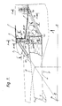
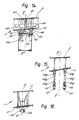
- an aircraft wing 1 includes a spanwise structural member 2 of box-shape in cross-section (a wing box) having a forward face 3 and a lower face or underside 4.
- An aircraft power plant 5 (shown generally) includes an engine whose fore-and-aft centre line is shown by line V-V, and a fore-and-aft extending beam member 6 from which the engine depends.
- the engine is carried at points 7 and 8.
- the beam member is of truncated form with its rearmost edge region 9 lying generally below the forward face 3 of the wing box even though the forward face 3 of the wing box is swept and the rearmost edge region 9 of the beam member is not swept in this example.
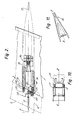
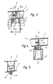
- the beam member is of generally rectangular shape in cross section, as shown in the cross sections of Figure 3 and 4; it has an upper surface region 10.
- Interconnecting means between the fore-and-aft extending beam member 6 and the spanwise structural member 2 (the wing box) of the wing are provided in the form of a forward element 11 which has one end pinned to lugs 12 projecting from an upper region of the forward face 3 of the wing box and the other end pinned to lugs 13 projecting from the upper surface 10 of the beam member 6 such that the element 11 extends obliquely downwards from the wing to the beam member.
- the lugs 12 and 13 are positioned such that the axes of their pins are aligned with the centre of gravity 14 of the engine when viewed from the side, as illustrated in Figure 1.
- a rearward element of the interconnecting means is provided in the form of an A-shaped frame 15 having its apex end pinned to lugs 16 depending from the underside 4 of the wing box and having its base end pivoted to laterally spaced lugs 17 extending rearwards from a lower part of the rearmost edge region 9 of the beam member.
- An intermediate element of the interconnecting means that is to say that element lying between the forward and the rearward elements, is provided in the form of twin laterally spaced co-axial pins 18 pinning spaced lugs 19 depending from the underside 4 of the wing box, forward of those lugs 16, to further spaced lugs 20 protruding upwards from the junction of the upper part of the rearmost edge region 9 and the rear portion of the upper surface 10 of the beam member.
- twin links 21 and 22 are conveniently positioned forward of the pins 18 and of the front face 3 of the wing box but rearwardly of the lugs 13.
- the links 21 and 22 are each pinned at one end to a member 23 protruding upwards from the beam member. That referenced 21, being pivoted about generally upright axes, is pinned to a lug 24 on the forward face 3 of the wing box, whilst that referenced 22, being pivoted about generally fore-and-aft axes, is pinned to a lug 25 formed upon one of the lugs 19.
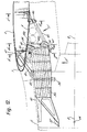
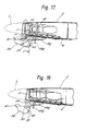
- an aircraft wing 1 includes a spanwise structural member 2 of box-shape in cross-section (a wing box) having a forward face 3 and a lower face or underside 4.
- An aircraft power plant 5 (shown generally) includes an engine whose fore-and-aft centre line is shown by line V-V, and a fore-and-aft extending beam member 36 from which the engine depends. The engine is carried at points 37 and 38.
- the beam member is of truncated form with its rearmost edge region 39 lying generally below the forward face 3 of the wing box even though the forward face 3 of the wing box is swept and the rearmost edge 39 of the beam member is not swept in this example.
- the beam member is of generally rectangular shape in cross section, as shown in the cross section of Figure 14; it has an upper surface region 40.
- Interconnecting means between the fore-and-aft extending beam member 36 and the spanwise structural member 2 (the wing box) of the wing are provided in the form of a forward element 41 which has one end pinned to lugs 42 projecting from an upper region of the forward face 3 of the wing box and the other end pinned to lugs 43 projecting from the upper surface 40 of the beam member 36 such that the element 41 extends obliquely downwards from the wing to the beam member.
- the lugs 42 and 43 are positioned such that the axes of their pins are approximately aligned with the centre of gravity 44 of the engine when viewed from the side as illustrated in Figure 12.
- a rearward element of the interconnecting means is provided in the form of an A-shaped frame 45 having its apex end pinned to a part-spherical portion of a pin 46 depending from the underside 4 of the wing box and having its base end pivoted to laterally spaced lugs 47 extending rearwards from a lower part of the rearmost edge region 39 of the beam member.
- Lugs 45a formed upon the spaced regions of the base end of the A-frame 45 are connected to corresponding lugs 49a depending from the underside 4 of the wing box by means of twin generally upright rods 45b.
- An intermediate element of the interconnecting means that is to say that element lying between the forward and the rearward elements, is provided in the form of twin laterally spaced co-axial pins 48 pinning spaced lugs 49 depending from the underside 4 of the wing box, forward of the pin 46, to further spaced lugs 50 protruding upwards from the junction of the upper part of the rearmost edge region 39 and the rear portion of the upper surface 40 of the beam member.
- a further connecting element is provided by a link 51.
- This is conveniently positioned forward of the pins 48 and of the front face 3 of the wing box but rearwardly of the lugs 43.
- the link 51 is pinned about generally fore-and-aft axes to a member 53 protruding upwards from the beam member and to a lug 55 formed upon one of the lugs 49.
- the power plant attachments are not handed, that is to say they are interchangeable between the right and left wings of the aircraft, all the pinned joints can have plain bearings, and, as previously discussed, the excess loads occasioned by any single failure of an interconnection element can be absorbed by the remaining elements without further failure; in other words, the attachment arrangement described has fully redundant load paths.
- the disposition of the A-frame 45 and the rods 45b on the wing box allows these items to be carried by the wing prior to assembly with the beam member 36.
- the part-spherical region of the pin 46 is eccentrically mounted to provide fine positional adjustment when the beam member 36 is connected during assembly.
Landscapes
- Engineering & Computer Science (AREA)
- Aviation & Aerospace Engineering (AREA)
- Body Structure For Vehicles (AREA)
- Transmission Devices (AREA)
Claims (9)
Applications Claiming Priority (2)
| Application Number | Priority Date | Filing Date | Title |
|---|---|---|---|
| GB8300748 | 1983-01-12 | ||
| GB838300748A GB8300748D0 (en) | 1983-01-12 | 1983-01-12 | Power plant attachment for aircraft wings |
Publications (2)
| Publication Number | Publication Date |
|---|---|
| EP0115914A1 EP0115914A1 (de) | 1984-08-15 |
| EP0115914B1 true EP0115914B1 (de) | 1987-01-14 |
Family
ID=10536230
Family Applications (1)
| Application Number | Title | Priority Date | Filing Date |
|---|---|---|---|
| EP84300173A Expired EP0115914B1 (de) | 1983-01-12 | 1984-01-12 | Anordnung der Triebwerksbefestigungen für Flugzeugtragflügel |
Country Status (4)
| Country | Link |
|---|---|
| US (1) | US4560122A (de) |
| EP (1) | EP0115914B1 (de) |
| DE (1) | DE3462003D1 (de) |
| GB (1) | GB8300748D0 (de) |
Cited By (3)
| Publication number | Priority date | Publication date | Assignee | Title |
|---|---|---|---|---|
| US7165744B2 (en) | 2004-01-21 | 2007-01-23 | Rolls-Royce Plc | Turbine engine arrangements |
| RU2304548C1 (ru) * | 2005-12-23 | 2007-08-20 | Закрытое акционерное общество "Гражданские самолеты Сухого" | Подвес двигателя к стреловидному крылу |
| EP4467461A1 (de) * | 2023-05-23 | 2024-11-27 | Airbus Operations (S.A.S.) | Anordnung für ein flugzeug mit einem flügel und einem triebwerkmast zur kopplung eines antriebssystems an den flügel |
Families Citing this family (41)
| Publication number | Priority date | Publication date | Assignee | Title |
|---|---|---|---|---|
| US5064144A (en) * | 1987-05-19 | 1991-11-12 | The Boeing Company | Engine mounting assembly |
| US4854525A (en) * | 1987-05-19 | 1989-08-08 | The Boeing Company | Engine mounting assembly |
| US4805851A (en) * | 1987-08-10 | 1989-02-21 | Herbst Paul T | Turbine engine mounting bracket assembly |
| US4917331A (en) * | 1988-11-10 | 1990-04-17 | The Boeing Company | Apparatus and methods for reducing aircraft lifting surface flutter |
| DE69012071T2 (de) * | 1989-12-05 | 1995-04-13 | Rolls Royce Plc | Ausfallsichere Haltevorrichtung für Treibwerke. |
| US5174525A (en) * | 1991-09-26 | 1992-12-29 | General Electric Company | Structure for eliminating lift load bending in engine core of turbofan |
| US5239822A (en) * | 1992-01-14 | 1993-08-31 | The Boeing Company | Composite structure for thrust reverser torque box |
| US5467941A (en) * | 1993-12-30 | 1995-11-21 | The Boeing Company | Pylon and engine installation for ultra-high by-pass turbo-fan engines |
| WO1996018538A1 (en) * | 1994-12-12 | 1996-06-20 | United Technologies Corporation | A mounting arrangement for a gas turbine engine |
| WO1996020111A1 (en) * | 1994-12-23 | 1996-07-04 | United Technologies Corporation | A mounting arrangement for a gas turbine engine |
| GB2303884B (en) * | 1995-04-13 | 1999-07-14 | Rolls Royce Plc | A mounting for coupling a turbofan gas turbine engine to an aircraft structure |
| FR2755942B1 (fr) * | 1996-11-21 | 1998-12-24 | Snecma | Suspension avant redondante pour turbomachine |
| FR2755943B1 (fr) * | 1996-11-21 | 1998-12-24 | Snecma | Suspension avant redondante pour turbomachine |
| FR2755944B1 (fr) * | 1996-11-21 | 1998-12-24 | Snecma | Suspension avant redondante pour turbomachine |
| US6095456A (en) * | 1996-12-23 | 2000-08-01 | The Boeing Company | Strut-wing interface having dual upper links |
| US6189830B1 (en) * | 1999-02-26 | 2001-02-20 | The Boeing Company | Tuned engine mounting system for jet aircraft |
| GB2360749A (en) * | 2000-03-28 | 2001-10-03 | Rolls Royce Plc | Aircraft turbofan gas turbine engine upstream core mounting which does not transmit vertical loads |
| FR2836672B1 (fr) * | 2002-03-04 | 2004-06-04 | Airbus France | Mat d'accrochage d'un moteur sous une voilure d'aeronef |
| FR2862611B1 (fr) * | 2003-11-25 | 2007-03-09 | Airbus France | Dispositif d'accrochage d'un moteur sous une voilure d'aeronef |
| EP1690790B1 (de) | 2005-02-11 | 2008-03-05 | ROLLS-ROYCE plc | Triebwerkanordnung |
| FR2889163B1 (fr) * | 2005-07-29 | 2007-09-07 | Airbus France Sas | Ensemble pour aeronef comprenant un element de voilure ainsi qu'un mat d'accrochage |
| FR2891256B1 (fr) * | 2005-09-27 | 2007-10-26 | Airbus France Sas | Dispositif d'accrochage d'un moteur interpose entre une voilure d'aeronef et ledit moteur |
| FI118761B (fi) * | 2006-02-09 | 2008-03-14 | Patria Aerostructures Oy | Ilma-aluksen siipi, kiinnitysjärjestely sekä välituki |
| FR2931133B1 (fr) * | 2008-05-14 | 2010-06-18 | Airbus France | Mat d'accrochage de moteur comprenant des moyens de fixation des longerons et des panneaux agences en dehors de l'espace interieur de caisson |
| FR2964364B1 (fr) * | 2010-09-03 | 2012-09-28 | Airbus Operations Sas | Mat d'accrochage de turboreacteur pour aeronef comprenant des attaches voilure avant alignees |
| FR2965548B1 (fr) * | 2010-10-01 | 2012-10-19 | Airbus Operations Sas | Mat d'accrochage d'un moteur d'aeronef comprenant deux attaches voilure avant a pions de cisaillement orthogonaux |
| US9027875B2 (en) * | 2010-10-28 | 2015-05-12 | Spirit Aerosystems, Inc. | Pylon arrangement for open structure |
| FR2981046B1 (fr) * | 2011-10-06 | 2013-10-25 | Aircelle Sa | Ensemble propulsif d'aeronef |
| FR3012793B1 (fr) * | 2013-11-05 | 2017-05-05 | Airbus Operations Sas | Ensemble pour aeronef comprenant une ferrure fixee sur la partie extrados d'un caisson de voilure, pour le montage d'un mat d'accrochage sur ce caisson de voilure |
| FR3015434B1 (fr) * | 2013-12-23 | 2017-12-08 | Snecma | Suspension de turbomachine |
| US10604265B2 (en) * | 2016-11-15 | 2020-03-31 | The Boeing Company | Integrated strut support fittings with underwing longerons |
| FR3073824B1 (fr) | 2017-11-23 | 2019-12-20 | Airbus Operations | Ensemble pour aeronef comprenant une structure primaire de mat d'accrochage fixee a un caisson de voilure par des attaches partiellement enterrees dans la structure primaire |
| US10597144B2 (en) * | 2017-12-01 | 2020-03-24 | Hadie Fotouhie | Under the wing-mounted jet engine with pivotal swivel joint to produce directional thrust vectoring thru swivel angle |
| FR3078950B1 (fr) * | 2018-03-15 | 2020-12-18 | Airbus Operations Sas | Structure primaire d'un mat de support d'un groupe propulseur d'aeronef dont la partie arriere est formee par un ensemble de bielles |
| FR3106126B1 (fr) * | 2020-01-10 | 2022-01-07 | Safran Aircraft Engines | Assemblage entre un pylône d’aéronef et une turbomachine |
| EP3939891B1 (de) * | 2020-07-17 | 2023-04-26 | Airbus Operations (S.A.S.) | Anordnung für ein luftfahrzeug aus einem flügel und einem triebwerksträger zur ankopplung eines turbotriebwerks an diesen flügel |
| US12337976B2 (en) | 2022-11-02 | 2025-06-24 | The Boeing Company | Systems and methods for coupling a strut to a wing of an aircraft |
| US12030614B2 (en) | 2022-11-04 | 2024-07-09 | The Boeing Company | Systems and methods for coupling a strut to a wing of an aircraft |
| FR3141676A1 (fr) * | 2022-11-08 | 2024-05-10 | Airbus Operations | Ensemble pour un aéronef comportant une aile et un mât réacteur pour coupler un système de propulsion à ladite aile |
| FR3152495A1 (fr) * | 2023-08-31 | 2025-03-07 | Airbus Operations | Ensemble pour un aéronef comportant une aile et un mât réacteur pour coupler un système de propulsion à ladite aile |
| FR3152496A1 (fr) * | 2023-09-04 | 2025-03-07 | Airbus Operations (S.A.S.) | Aéronef comportant au moins un système d’attache moteur présentant des attaches voilures positionnées approximativement dans un plan longitudinal médian |
Family Cites Families (6)
| Publication number | Priority date | Publication date | Assignee | Title |
|---|---|---|---|---|
| FR1471132A (fr) * | 1966-03-15 | 1967-02-24 | Rolls Royce | Structure pour le montage de moteurs applicables, notamment, aux avions |
| US3831888A (en) * | 1972-07-27 | 1974-08-27 | Mc Donnell Douglas Corp | Aircraft engine suspension system |
| US3844115A (en) * | 1973-02-14 | 1974-10-29 | Gen Electric | Load distributing thrust mount |
| GB1516980A (en) * | 1974-12-24 | 1978-07-05 | Rolls Royce | Mounting ducted fan gas turbine engines on aircraft |
| GB2010969A (en) * | 1977-12-22 | 1979-07-04 | Rolls Royce | Mounting for Gas Turbine Jet Propulsion Engine |
| US4266741A (en) * | 1978-05-22 | 1981-05-12 | The Boeing Company | Mounting apparatus for fan jet engine having mixed flow nozzle installation |
-
1983
- 1983-01-12 GB GB838300748A patent/GB8300748D0/en active Pending
-
1984
- 1984-01-11 US US06/569,896 patent/US4560122A/en not_active Expired - Fee Related
- 1984-01-12 EP EP84300173A patent/EP0115914B1/de not_active Expired
- 1984-01-12 DE DE8484300173T patent/DE3462003D1/de not_active Expired
Cited By (5)
| Publication number | Priority date | Publication date | Assignee | Title |
|---|---|---|---|---|
| US7165744B2 (en) | 2004-01-21 | 2007-01-23 | Rolls-Royce Plc | Turbine engine arrangements |
| RU2304548C1 (ru) * | 2005-12-23 | 2007-08-20 | Закрытое акционерное общество "Гражданские самолеты Сухого" | Подвес двигателя к стреловидному крылу |
| EP4467461A1 (de) * | 2023-05-23 | 2024-11-27 | Airbus Operations (S.A.S.) | Anordnung für ein flugzeug mit einem flügel und einem triebwerkmast zur kopplung eines antriebssystems an den flügel |
| FR3148995A1 (fr) * | 2023-05-23 | 2024-11-29 | Airbus Operations | Ensemble pour un aéronef comportant une aile et un mât réacteur pour coupler un système de propulsion à ladite aile |
| US12397899B2 (en) | 2023-05-23 | 2025-08-26 | Airbus Operations Sas | Assembly for an aircraft comprising a wing and an engine pylon for coupling a propulsion system to said wing |
Also Published As
| Publication number | Publication date |
|---|---|
| EP0115914A1 (de) | 1984-08-15 |
| DE3462003D1 (en) | 1987-02-19 |
| GB8300748D0 (en) | 1983-02-16 |
| US4560122A (en) | 1985-12-24 |
Similar Documents
| Publication | Publication Date | Title |
|---|---|---|
| EP0115914B1 (de) | Anordnung der Triebwerksbefestigungen für Flugzeugtragflügel | |
| US8336812B2 (en) | Engine attachment for an assembly system mounted between an attachment strut and an aircraft engine | |
| US8991762B2 (en) | Wing/fuselage connection of an aircraft | |
| EP2018316B1 (de) | Bodenstruktur für rumpf | |
| US4365773A (en) | Joined wing aircraft | |
| US6938855B2 (en) | Hooking strut of an engine under the wing unit of an aircraft | |
| EP0067208B1 (de) | Kombinierte balkenstütze für fahrgestell | |
| JP2010508199A5 (de) | ||
| EP2470426B1 (de) | Flugzeug mit zwei am heck montierten elektrischen antrieben | |
| US6805320B2 (en) | Aircraft landing gear with highly offset strut pivot axis | |
| CN114735193B (zh) | 拦阻墙与机身柔性连接结构以及飞机 | |
| CN113942652A (zh) | 具有机翼和发动机吊挂架的飞行器组件 | |
| US6345787B1 (en) | Aircraft landing gear | |
| US20200017227A1 (en) | Mounting pylon for a jet engine of an aircraft comprising a particular structure | |
| WO1988006551A1 (en) | An improved aircraft | |
| US3565369A (en) | Aircraft having variable sweep-back wings | |
| US20220306271A1 (en) | Aircraft empennage | |
| CN219447326U (zh) | 具有防倾结构的飞行器测试平台 | |
| CN110893905A (zh) | 具有简化结构的飞行器的前段区域 | |
| CN219215361U (zh) | 抗鸟撞的飞机尾翼前缘结构 | |
| US2123665A (en) | Wing attaching hull superstructure | |
| US11208194B2 (en) | Assembly for warping of an aerodynamic structure | |
| WO1980000243A1 (en) | Aircraft | |
| EP4656513A1 (de) | Luftfahrzeug mit mindestens einem flügelbefestigungssystem, das mindestens eine seitenstange aufweist | |
| US1917530A (en) | Aircraft of the rotative-blade type |
Legal Events
| Date | Code | Title | Description |
|---|---|---|---|
| PUAI | Public reference made under article 153(3) epc to a published international application that has entered the european phase |
Free format text: ORIGINAL CODE: 0009012 |
|
| AK | Designated contracting states |
Designated state(s): DE FR GB IT NL |
|
| 17P | Request for examination filed |
Effective date: 19841120 |
|
| GRAA | (expected) grant |
Free format text: ORIGINAL CODE: 0009210 |
|
| AK | Designated contracting states |
Kind code of ref document: B1 Designated state(s): DE FR GB IT NL |
|
| ITF | It: translation for a ep patent filed | ||
| REF | Corresponds to: |
Ref document number: 3462003 Country of ref document: DE Date of ref document: 19870219 |
|
| ET | Fr: translation filed | ||
| PLBE | No opposition filed within time limit |
Free format text: ORIGINAL CODE: 0009261 |
|
| STAA | Information on the status of an ep patent application or granted ep patent |
Free format text: STATUS: NO OPPOSITION FILED WITHIN TIME LIMIT |
|
| 26N | No opposition filed | ||
| PG25 | Lapsed in a contracting state [announced via postgrant information from national office to epo] |
Ref country code: GB Effective date: 19890112 |
|
| PG25 | Lapsed in a contracting state [announced via postgrant information from national office to epo] |
Ref country code: NL Effective date: 19890801 |
|
| NLV4 | Nl: lapsed or anulled due to non-payment of the annual fee | ||
| GBPC | Gb: european patent ceased through non-payment of renewal fee | ||
| PG25 | Lapsed in a contracting state [announced via postgrant information from national office to epo] |
Ref country code: FR Free format text: LAPSE BECAUSE OF NON-PAYMENT OF DUE FEES Effective date: 19890929 |
|
| PG25 | Lapsed in a contracting state [announced via postgrant information from national office to epo] |
Ref country code: DE Effective date: 19891003 |
|
| REG | Reference to a national code |
Ref country code: FR Ref legal event code: ST |