EP4516448A1 - Machine-outil à commande numérique comportant une tourelle multibroches et un dispositif de préhension d'outils - Google Patents
Machine-outil à commande numérique comportant une tourelle multibroches et un dispositif de préhension d'outils Download PDFInfo
- Publication number
- EP4516448A1 EP4516448A1 EP24191576.8A EP24191576A EP4516448A1 EP 4516448 A1 EP4516448 A1 EP 4516448A1 EP 24191576 A EP24191576 A EP 24191576A EP 4516448 A1 EP4516448 A1 EP 4516448A1
- Authority
- EP
- European Patent Office
- Prior art keywords
- tool
- spindle
- magazine
- machine tool
- spindles
- Prior art date
- Legal status (The legal status is an assumption and is not a legal conclusion. Google has not performed a legal analysis and makes no representation as to the accuracy of the status listed.)
- Pending
Links
Images
Classifications
-
- B—PERFORMING OPERATIONS; TRANSPORTING
- B23—MACHINE TOOLS; METAL-WORKING NOT OTHERWISE PROVIDED FOR
- B23Q—DETAILS, COMPONENTS, OR ACCESSORIES FOR MACHINE TOOLS, e.g. ARRANGEMENTS FOR COPYING OR CONTROLLING; MACHINE TOOLS IN GENERAL CHARACTERISED BY THE CONSTRUCTION OF PARTICULAR DETAILS OR COMPONENTS; COMBINATIONS OR ASSOCIATIONS OF METAL-WORKING MACHINES, NOT DIRECTED TO A PARTICULAR RESULT
- B23Q3/00—Devices holding, supporting, or positioning work or tools, of a kind normally removable from the machine
- B23Q3/155—Arrangements for automatic insertion or removal of tools, e.g. combined with manual handling
- B23Q3/157—Arrangements for automatic insertion or removal of tools, e.g. combined with manual handling of rotary tools
- B23Q3/15713—Arrangements for automatic insertion or removal of tools, e.g. combined with manual handling of rotary tools a transfer device taking a single tool from a storage device and inserting it in a spindle
- B23Q3/1572—Arrangements for automatic insertion or removal of tools, e.g. combined with manual handling of rotary tools a transfer device taking a single tool from a storage device and inserting it in a spindle the storage device comprising rotating or circulating storing means
- B23Q3/15722—Rotary discs or drums
-
- B—PERFORMING OPERATIONS; TRANSPORTING
- B23—MACHINE TOOLS; METAL-WORKING NOT OTHERWISE PROVIDED FOR
- B23Q—DETAILS, COMPONENTS, OR ACCESSORIES FOR MACHINE TOOLS, e.g. ARRANGEMENTS FOR COPYING OR CONTROLLING; MACHINE TOOLS IN GENERAL CHARACTERISED BY THE CONSTRUCTION OF PARTICULAR DETAILS OR COMPONENTS; COMBINATIONS OR ASSOCIATIONS OF METAL-WORKING MACHINES, NOT DIRECTED TO A PARTICULAR RESULT
- B23Q3/00—Devices holding, supporting, or positioning work or tools, of a kind normally removable from the machine
- B23Q3/155—Arrangements for automatic insertion or removal of tools, e.g. combined with manual handling
- B23Q3/15506—Arrangements for automatic insertion or removal of tools, e.g. combined with manual handling the tool being inserted in a tool holder directly from a storage device (without transfer device)
-
- B—PERFORMING OPERATIONS; TRANSPORTING
- B23—MACHINE TOOLS; METAL-WORKING NOT OTHERWISE PROVIDED FOR
- B23Q—DETAILS, COMPONENTS, OR ACCESSORIES FOR MACHINE TOOLS, e.g. ARRANGEMENTS FOR COPYING OR CONTROLLING; MACHINE TOOLS IN GENERAL CHARACTERISED BY THE CONSTRUCTION OF PARTICULAR DETAILS OR COMPONENTS; COMBINATIONS OR ASSOCIATIONS OF METAL-WORKING MACHINES, NOT DIRECTED TO A PARTICULAR RESULT
- B23Q3/00—Devices holding, supporting, or positioning work or tools, of a kind normally removable from the machine
- B23Q3/155—Arrangements for automatic insertion or removal of tools, e.g. combined with manual handling
- B23Q3/1552—Arrangements for automatic insertion or removal of tools, e.g. combined with manual handling parts of devices for automatically inserting or removing tools
- B23Q3/15526—Storage devices; Drive mechanisms therefor
- B23Q3/15534—Magazines mounted on the spindle
-
- B—PERFORMING OPERATIONS; TRANSPORTING
- B23—MACHINE TOOLS; METAL-WORKING NOT OTHERWISE PROVIDED FOR
- B23Q—DETAILS, COMPONENTS, OR ACCESSORIES FOR MACHINE TOOLS, e.g. ARRANGEMENTS FOR COPYING OR CONTROLLING; MACHINE TOOLS IN GENERAL CHARACTERISED BY THE CONSTRUCTION OF PARTICULAR DETAILS OR COMPONENTS; COMBINATIONS OR ASSOCIATIONS OF METAL-WORKING MACHINES, NOT DIRECTED TO A PARTICULAR RESULT
- B23Q3/00—Devices holding, supporting, or positioning work or tools, of a kind normally removable from the machine
- B23Q3/155—Arrangements for automatic insertion or removal of tools, e.g. combined with manual handling
- B23Q3/1552—Arrangements for automatic insertion or removal of tools, e.g. combined with manual handling parts of devices for automatically inserting or removing tools
-
- B—PERFORMING OPERATIONS; TRANSPORTING
- B23—MACHINE TOOLS; METAL-WORKING NOT OTHERWISE PROVIDED FOR
- B23B—TURNING; BORING
- B23B29/00—Holders for non-rotary cutting tools; Boring bars or boring heads; Accessories for tool holders
- B23B29/24—Tool holders for a plurality of cutting tools, e.g. turrets
-
- B—PERFORMING OPERATIONS; TRANSPORTING
- B23—MACHINE TOOLS; METAL-WORKING NOT OTHERWISE PROVIDED FOR
- B23Q—DETAILS, COMPONENTS, OR ACCESSORIES FOR MACHINE TOOLS, e.g. ARRANGEMENTS FOR COPYING OR CONTROLLING; MACHINE TOOLS IN GENERAL CHARACTERISED BY THE CONSTRUCTION OF PARTICULAR DETAILS OR COMPONENTS; COMBINATIONS OR ASSOCIATIONS OF METAL-WORKING MACHINES, NOT DIRECTED TO A PARTICULAR RESULT
- B23Q1/00—Members which are comprised in the general build-up of a form of machine, particularly relatively large fixed members
- B23Q1/25—Movable or adjustable work or tool supports
-
- B—PERFORMING OPERATIONS; TRANSPORTING
- B23—MACHINE TOOLS; METAL-WORKING NOT OTHERWISE PROVIDED FOR
- B23Q—DETAILS, COMPONENTS, OR ACCESSORIES FOR MACHINE TOOLS, e.g. ARRANGEMENTS FOR COPYING OR CONTROLLING; MACHINE TOOLS IN GENERAL CHARACTERISED BY THE CONSTRUCTION OF PARTICULAR DETAILS OR COMPONENTS; COMBINATIONS OR ASSOCIATIONS OF METAL-WORKING MACHINES, NOT DIRECTED TO A PARTICULAR RESULT
- B23Q11/00—Accessories fitted to machine tools for keeping tools or parts of the machine in good working condition or for cooling work; Safety devices specially combined with or arranged in, or specially adapted for use in connection with, machine tools
- B23Q11/08—Protective coverings for parts of machine tools; Splash guards
-
- B—PERFORMING OPERATIONS; TRANSPORTING
- B23—MACHINE TOOLS; METAL-WORKING NOT OTHERWISE PROVIDED FOR
- B23Q—DETAILS, COMPONENTS, OR ACCESSORIES FOR MACHINE TOOLS, e.g. ARRANGEMENTS FOR COPYING OR CONTROLLING; MACHINE TOOLS IN GENERAL CHARACTERISED BY THE CONSTRUCTION OF PARTICULAR DETAILS OR COMPONENTS; COMBINATIONS OR ASSOCIATIONS OF METAL-WORKING MACHINES, NOT DIRECTED TO A PARTICULAR RESULT
- B23Q3/00—Devices holding, supporting, or positioning work or tools, of a kind normally removable from the machine
- B23Q3/155—Arrangements for automatic insertion or removal of tools, e.g. combined with manual handling
- B23Q3/1552—Arrangements for automatic insertion or removal of tools, e.g. combined with manual handling parts of devices for automatically inserting or removing tools
- B23Q3/15526—Storage devices; Drive mechanisms therefor
-
- B—PERFORMING OPERATIONS; TRANSPORTING
- B23—MACHINE TOOLS; METAL-WORKING NOT OTHERWISE PROVIDED FOR
- B23Q—DETAILS, COMPONENTS, OR ACCESSORIES FOR MACHINE TOOLS, e.g. ARRANGEMENTS FOR COPYING OR CONTROLLING; MACHINE TOOLS IN GENERAL CHARACTERISED BY THE CONSTRUCTION OF PARTICULAR DETAILS OR COMPONENTS; COMBINATIONS OR ASSOCIATIONS OF METAL-WORKING MACHINES, NOT DIRECTED TO A PARTICULAR RESULT
- B23Q39/00—Metal-working machines incorporating a plurality of sub-assemblies, each capable of performing a metal-working operation
- B23Q39/02—Metal-working machines incorporating a plurality of sub-assemblies, each capable of performing a metal-working operation the sub-assemblies being capable of being brought to act at a single operating station
- B23Q39/021—Metal-working machines incorporating a plurality of sub-assemblies, each capable of performing a metal-working operation the sub-assemblies being capable of being brought to act at a single operating station with a plurality of toolheads per workholder, whereby the toolhead is a main spindle, a multispindle, a revolver or the like
- B23Q39/022—Metal-working machines incorporating a plurality of sub-assemblies, each capable of performing a metal-working operation the sub-assemblies being capable of being brought to act at a single operating station with a plurality of toolheads per workholder, whereby the toolhead is a main spindle, a multispindle, a revolver or the like with same working direction of toolheads on same workholder
- B23Q39/024—Metal-working machines incorporating a plurality of sub-assemblies, each capable of performing a metal-working operation the sub-assemblies being capable of being brought to act at a single operating station with a plurality of toolheads per workholder, whereby the toolhead is a main spindle, a multispindle, a revolver or the like with same working direction of toolheads on same workholder consecutive working of toolheads
-
- B—PERFORMING OPERATIONS; TRANSPORTING
- B23—MACHINE TOOLS; METAL-WORKING NOT OTHERWISE PROVIDED FOR
- B23Q—DETAILS, COMPONENTS, OR ACCESSORIES FOR MACHINE TOOLS, e.g. ARRANGEMENTS FOR COPYING OR CONTROLLING; MACHINE TOOLS IN GENERAL CHARACTERISED BY THE CONSTRUCTION OF PARTICULAR DETAILS OR COMPONENTS; COMBINATIONS OR ASSOCIATIONS OF METAL-WORKING MACHINES, NOT DIRECTED TO A PARTICULAR RESULT
- B23Q3/00—Devices holding, supporting, or positioning work or tools, of a kind normally removable from the machine
- B23Q3/155—Arrangements for automatic insertion or removal of tools, e.g. combined with manual handling
- B23Q3/1552—Arrangements for automatic insertion or removal of tools, e.g. combined with manual handling parts of devices for automatically inserting or removing tools
- B23Q3/15526—Storage devices; Drive mechanisms therefor
- B23Q2003/15537—Linearly moving storage devices
-
- B—PERFORMING OPERATIONS; TRANSPORTING
- B23—MACHINE TOOLS; METAL-WORKING NOT OTHERWISE PROVIDED FOR
- B23Q—DETAILS, COMPONENTS, OR ACCESSORIES FOR MACHINE TOOLS, e.g. ARRANGEMENTS FOR COPYING OR CONTROLLING; MACHINE TOOLS IN GENERAL CHARACTERISED BY THE CONSTRUCTION OF PARTICULAR DETAILS OR COMPONENTS; COMBINATIONS OR ASSOCIATIONS OF METAL-WORKING MACHINES, NOT DIRECTED TO A PARTICULAR RESULT
- B23Q3/00—Devices holding, supporting, or positioning work or tools, of a kind normally removable from the machine
- B23Q3/155—Arrangements for automatic insertion or removal of tools, e.g. combined with manual handling
- B23Q2003/15586—Arrangements for automatic insertion or removal of tools, e.g. combined with manual handling of tools in turrets
-
- B—PERFORMING OPERATIONS; TRANSPORTING
- B23—MACHINE TOOLS; METAL-WORKING NOT OTHERWISE PROVIDED FOR
- B23Q—DETAILS, COMPONENTS, OR ACCESSORIES FOR MACHINE TOOLS, e.g. ARRANGEMENTS FOR COPYING OR CONTROLLING; MACHINE TOOLS IN GENERAL CHARACTERISED BY THE CONSTRUCTION OF PARTICULAR DETAILS OR COMPONENTS; COMBINATIONS OR ASSOCIATIONS OF METAL-WORKING MACHINES, NOT DIRECTED TO A PARTICULAR RESULT
- B23Q39/00—Metal-working machines incorporating a plurality of sub-assemblies, each capable of performing a metal-working operation
- B23Q2039/004—Machines with tool turrets
Definitions
- the invention relates to the field of numerically controlled machine tools intended for the machining of preferably micromechanical parts and to that of the equipment of such machines.
- the invention relates to a numerically controlled machine tool comprising a multi-spindle turret and a tool gripping device.
- Numerical control machine tools are designed to mass produce parts, particularly by machining, following the instructions of a computer program. These machines have a tool mounted in a tool spindle and are generally equipped with a tool changer to exchange the tool held by the tool spindle to adapt it to the machining operations to be carried out on the part held in position in a fixture.
- multi-spindle turrets comprising a head on which are arranged several tool spindles, one of which is active and the others are at rest.
- the spindle active tool holder is engaged with a drive mechanism by means of a coupling system.
- the tool change can be carried out by uncoupling the active tool holder spindle, i.e. the one carrying the tool to be changed, rotating the head so as to present the next tool holder spindle and coupling this tool holder spindle with the drive mechanism.
- the multi-spindle turrets of the state of the art are bulky, which generates significant moments of inertia and increases the risk of collision between the installation and the tools carried by the turret.
- the invention solves the above-mentioned drawbacks by proposing a solution making it possible to completely mask the tool change times and the tool replacement times, in particular by masking the tool acceleration and deceleration phases and by masking the cooperation times between the multi-spindle turret and the tool gripping device.
- the present invention relates to a numerically controlled machine tool
- a numerically controlled machine tool comprising a multi-spindle turret provided with a body extending along an axis A-A between a first end by which it is fixed to a frame of the machine tool and a second end at which it comprises a rotating movable head.
- the head comprises at least two tool-holder spindles, each intended to receive in engagement a cutting tool, the spindles occupying, depending on the angular position of the head, a working position in which they are intended to carry out a machining operation on a part held in position in a rest or a waiting position in which they are set back from said part.
- Each of the spindles is configured to be controlled independently of the other in order to immobilize or rotate the tool that it carries, regardless of the position that it occupies.
- the machine tool further comprises a tool gripping device configured to interact with a spindle in the waiting position so as to extract a tool to be stored carried by said spindle and to insert a replacement tool into said spindle.
- the present invention therefore makes it possible to carry out a tool change with a dead time reduced only to the duration of the rotation of the head until the next tool comes into contact with the workpiece while making it possible to carry out the replacement of a tool in masked time, during a machining operation, on a spindle in the waiting position.
- the gripping device comprises a tool magazine held in a cantilevered position by a supporting structure fixed to the turret body.
- the turret body is rigidly fixed to the frame, i.e. without any degree of freedom, as is the magazine, the latter comprising a storage barrel.
- the gripping device comprises a gripping member in the form of a transfer module movable between a position in which it is intended to interact with the magazine and a position in which it is intended to interact with one of the waiting spindles, the transfer module being provided with a gripping fork capable of gripping a tool.
- the magazine comprises a protective casing provided with a slot comprising an axial portion and a radial portion allowing the introduction, into the magazine, of the tool to be stored and the spindle, and allowing the release of said magazine once the tool has been replaced.
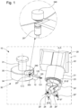
- the present invention relates to a numerically controlled machine tool 10 comprising, as shown in the figure 1 , a 20 multi-spindle turret intended for the machining of preferably micromechanical parts and a 30 tool gripping device.
- the turret 20 comprises a body 21 extending along a longitudinal axis denoted “axis AA”, comprising at one of its ends a base 22 for attachment to a frame 11 of the machine tool 10 and at the other end a head 23 movable in rotation about an axis coinciding with the axis AA in the exemplary embodiment of the invention shown in the figures.
- the head 23 comprises at least two tool-holder spindles 24, 24' or 24", each intended to receive in engagement a tool 25, 25' or 25".
- each spindle 24, 24' and 24" occupies a working position, in which it is intended to carry out a machining operation on a part held in position in a rest, or a waiting position, in which it is set back from the part.
- the turret 20 comprises three spindles 24, 24' and 24", one of which is in the working position and two are in the waiting position. It is understood here that the rotation of the head 23 causes the change of tools, the tool 25 occupying the working position being moved to a waiting position and one of the tools 25' or 25" in the waiting position being moved to the working position.
- the turret 20 is stationary, the base 22 being for example fixed directly to the frame 11 of the machine tool 10.
- the installation is then provided with the aforementioned degrees of freedom, for example three degrees of freedom in translation with reference to a trihedron XYZ, respectively in the directions X, Y and Z and possibly one or two degrees of freedom in rotation according to X and/or Y.
- the spindles 24, 24' and 24" are advantageously configured so as to be driven independently of each other in order to drive in rotation or to immobilize the tool 25, 25' or 25" that they carry. This characteristic is particularly advantageous during a tool change.
- the spindles 24, 24' and 24" are motorized spindles, also called “electro-spindles”, and each comprise a motor of its own for driving in rotation or immobilizing the tool 25, 25' or 25" that they carry.
- the first tool 25 is engaged in the spindle 24 in the working position and the second tool 25' or 25" is engaged in one of the spindles 24' or 24" in the waiting position.
- the head 23 is pivoted so as to drive the spindle 24 which was in the working position into the waiting position, and so as to drive the spindle 24' or 24" which was in the waiting position into the working position.
- the second machining phase then begins immediately, thanks to the fact that the second tool 25' or 25" has reached its machining rotation speed when the spindle 24' or 24" in which it is engaged was in the waiting position.
- the spindle 24 carrying the first tool 25 being now in the waiting position, the latter is then immobilized in rotation.
- the change of tools is carried out with a dead time reduced only to the duration of the rotation of the head 23 along the axis A-A.
- Each spindle 24, 24' and 24" extends respectively along a longitudinal axis denoted “axis BB", “axis B'-B'” and “axis B"-B”", also constituting their axis of rotation, as illustrated in the figure 1 .
- the spindle 24 is preferably oriented so that its axis BB is parallel to a vertical axis.
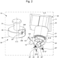
- the present invention makes it possible to replace a 25' or 25" tool to be stored carried by one of the 24' or 24" spindles in the waiting position and immobile in rotation during the performance of a machining operation, as shown in the figure 2 .
- the machine tool 10 comprises a tool gripping device 30 capable of extracting from a spindle 24' or 24" the tool 25' or 25" to be stored and of inserting into said spindle 24' or 24" a new tool, called "replacement tool"25'" in the remainder of the text.
- the gripping device 30 is directly fixed to the frame 11, as shown in the figures.
- the gripping device 30 comprises a tool magazine 34 held in a cantilevered position by a supporting structure 31.
- the magazine 34 comprises a tool storage barrel 340 comprising a plurality of housings intended to receive replacement tools 25'" or replaced tools.
- the housings may each comprise an opening opening radially or axially, through which they are capable of receiving in engagement a replacement tool 25'" or a replaced tool.
- a single replacement tool 25'" is shown in the figures for reasons of clarity.
- the storage barrel 340 can take the form of a disk on the periphery of which the housings are regularly distributed.
- the storage barrel 340 has a degree of freedom in rotation along an axis CC parallel to the axis B'-B' or the axis B"-B" of one of the pins 24' or 24" in the waiting position, in particular the pin 24', with which it interacts, so as to be able to present opposite said pin 24' each of the housings that it comprises.
- the tool gripping device 30 comprises a transfer module 12 movable between a first position, visible on the figure 1 , in which it interacted with store 34 and a second position, visible on the figure 2 , in which it interacts with one of the 24' or 24" pins in the waiting position, in particular the 24' pin.
- the latter In order to replace the tool 25' engaged in the spindle 24' in the waiting position with a replacement tool 25'" arranged in the storage barrel 340, the latter is pivoted so as to present an empty housing opposite the head 23, then the tool 25' to be stored is introduced into the housing by the transfer module 12. Depending on the configuration of the housing, the tool 25' to be stored is inserted into the housing by the transfer module 12. store is introduced axially or radially into the housing. The storage barrel 340 is then pivoted until the replacement tool 25'" is located opposite the head 23, then the replacement tool 25'" is removed from its housing by the transfer module 12, and the replacement tool 25'" is engaged in said spindle 24' by the transfer module 12.
- the housings are arranged so that their opening opens tangentially or orthoradially relative to the storage barrel 340, the engagement in a housing of the tool 25' to be stored, as well as the withdrawal from a housing of a replacement tool 25′′′, is carried out by a rotation of the storage barrel 340 along the axis C-C or by a rotation of the transfer module 12 along an axis parallel to the axis C-C, respectively in two opposite directions.
- the spindle 24' is controlled so as to release the tool 25' to be stored when the storage barrel 340 is moved in translation in a direction opposite to the spindle 24', and is configured so as to lock the replacement tool 25'" when it is introduced into the latter.
- the body 21 of the turret 20 is rigidly fixed to the frame 11, that is to say without any degree of freedom, as is the magazine 34, the latter being able to be fixed directly to the frame 11 or to the body 21 of the turret 20.
- the transfer module 12 is provided with a gripping fork 120 extending from a body 122 and being able to grip a tool 25' to be stored housed in the spindle 24' in the waiting position with which the transfer module 12 interacts when it is in the second position and to release this tool 25' when the latter is arranged in a housing of the storage barrel 340 and when the transfer module 12 is in its first position. position.
- the fork 120 is also able to grip a replacement tool 25'" when the transfer module 12 is in its first position, so as to extract it from its housing and release it when the replacement tool 25'" is engaged in the spindle 24', when the transfer module 12 is in its second position.
- the transfer module 12 is configured to be movable along a radial axis relative to the magazine 34 in order to introduce a tool 25' to be stored in a housing of the storage barrel 340 or to extract a replacement tool 25'" from a housing.
- the transfer module 12 is configured so as to be able to be moved in translation, on the one hand, along an axis parallel to the axis B'-B' of the spindle 24' with which it is intended to interact so as to extract from the latter a tool 25' to be stored or to introduce a replacement tool 25′′′, and on the other hand, along an axis orthogonal to the axis B'-B' to engage the fork 120 in a tool 25' to be stored or to disengage the fork 120 from a replacement tool 25'". Furthermore, the transfer module 12 has a degree of freedom in rotation so that the fork 120 is arranged successively opposite a housing and opposite the spindle 24' in the waiting position.
- the fork 120 may comprise at a free end a notch 121 intended to engage in an annular groove of the tool (not shown in the figures), to fix the latter to the transfer module 12 during its movements between its first and second positions.
- an annular groove is, as such, known to those skilled in the art.
- the notch 121 and/or the annular groove has an elastic deformation capacity in order to ensure that the tool is held by the fork 120.
- the transfer module 12 may comprise at least two forks 120, for example arranged so that one is diametrically opposite the other relative to the body 122. Similarly, if the transfer module 12 comprises more than two forks 120, these can advantageously be distributed regularly around the body 122. This arrangement makes it possible to optimize the movement time of the transfer module 12 insofar as, when it occupies the first position, the transfer module 12 can be driven so that, successively, one of the forks 120 extracts a replacement tool 25'" from a housing and the other places, in the housing, a tool 25" to be stored previously removed from the spindle 24".
- the transfer module 12 when the transfer module 12 occupies the second position, it can be driven so that, successively, one of the forks 120 removes from the spindle 24' a tool 25' to be stored and the other inserts into said spindle 24' a replacement tool 25'".
- the installation has degrees of mobility in translation and rotation adapted to executing a machining program.
- the magazine 34 comprises a protective casing 35 shown in these figures in the form of rigid walls having a shape of revolution. Due to the kinematics described above, the protective casing 35 comprises a slot 350 through which a 25', 25" or 25′′′ tool can pass.
Landscapes
- Engineering & Computer Science (AREA)
- Mechanical Engineering (AREA)
- Automatic Tool Replacement In Machine Tools (AREA)
- Cutting Tools, Boring Holders, And Turrets (AREA)
Abstract
Description
- L'invention relève du domaine des machines-outils à commande numérique destinées à l'usinage de pièces préférentiellement micromécaniques et de celui des équipements de telles machines.
- Plus particulièrement, l'invention concerne une machine-outil à commande numérique comportant une tourelle multibroches et un dispositif de préhension d'outils.
- Les machines-outils à commande numérique sont destinées à produire des pièces en série, notamment par usinage, en suivant les consignes d'un programme informatique. Ces machines comportent un outil monté dans une broche porte-outil et sont généralement équipées d'un changeur d'outils afin d'échanger l'outil maintenu par la broche porte-outil pour l'adapter aux opérations d'usinage à réaliser sur la pièce maintenue en position dans un posage.
- Lors d'un changement d'outils, la machine-outil n'est plus productive dans le sens où les opérations d'usinage sont interrompues. Il est donc recherché de minimiser la durée de changement d'outils. À cet effet, des changeurs d'outils ont été développés pour travailler au maximum en temps masqué et minimiser les temps de pause des machines-outils afin d'augmenter leur productivité.
- Par exemple, on connait les tourelles multibroches comprenant une tête sur laquelle sont agencées plusieurs broches porte-outils parmi lesquelles une est active et les autres sont au repos. En particulier, la broche porte-outil active est en prise avec un mécanisme d'entraînement grâce à un système d'accouplement. Ainsi, entre deux opérations d'usinage, le changement d'outils peut être réalisé par désaccouplement de la broche porte-outil active, c'est-à-dire celle portant l'outil à changer, rotation de la tête de sorte à présenter la broche porte-outil suivante et accouplement de cette broche porte-outil avec le mécanisme d'entraînement.
- Cette solution ne donne toutefois pas entière satisfaction dans la mesure où, bien qu'ils soient réduits, les temps de changement d'outils ne sont pas entièrement masqués. En effet, entre chaque changement d'outils, avec ce type de tourelle multibroches, il est nécessaire de freiner l'outil à changer avant de réaliser le changement d'outils et d'accélérer l'outil suivant une fois qu'il est accouplé au mécanisme d'entraînement, jusqu'à ce qu'il atteigne sa vitesse de rotation d'usinage. Ces tourelles multibroches requièrent également un certain laps de temps pour désaccoupler l'outil à changer, pivoter la tête et indexer l'outil suivant afin de l'aligner avec le système d'accouplement, puis réaliser l'accouplement. Aussi, cette solution est particulièrement complexe et onéreuse du fait du système d'accouplement.
- Il existe des tourelles multibroches répondant à la problématique d'accélération et de freinage de broche porte-outil, dans lesquelles les outils sont tous entraînés en rotation, de façon synchrone. Ainsi, lors du changement d'outils, l'outil suivant est déjà entraîné à sa vitesse de rotation d'usinage et peut débuter l'opération d'usinage de la pièce. Ces tourelles multibroches engendrent cependant une consommation de grandes quantités d'énergie pour entraîner en rotation l'ensemble des outils de façon simultané. Par ailleurs, la vitesse de rotation maximale des outils qu'elles portent est relativement limitée du fait de la chaine cinématique de transmission de mouvement.
- Globalement, qu'elles entraînent en rotation les outils qu'elles portent de façon individuelle ou simultanée, les tourelles multibroches de l'état de la technique sont volumineuses, ce qui engendre des moments d'inertie importants et augmente le risque de collision entre le posage et les outils portés par la tourelle.
- On comprend qu'en plus des inconvénients précités, ces solutions ne sont pas adaptées pour l'usinage de pièces micromécaniques.
- L'invention résout les inconvénients précités en proposant une solution permettant de masquer complètement les temps de changement d'outils et les temps de remplacement d'outils, notamment en masquant les phases d'accélération et de décélération des outils et en masquant les temps de coopération entre la tourelle multibroche et le dispositif de préhension d'outils.
- À cet effet, la présente invention concerne une machine-outil à commande numérique comprenant une tourelle multibroches dotée d'un corps s'étendant selon un axe A-A entre une première extrémité par laquelle il est fixé à un bâti de la machine-outil et une seconde extrémité au niveau de laquelle il comporte une tête mobile en rotation. La tête comprend au moins deux broches porte-outils, chacune étant destinée à recevoir en engagement un outil de coupe, les broches occupant, selon la position angulaire de la tête, une position de travail dans laquelle elles sont destinées à réaliser une opération d'usinage d'une pièce maintenue en position dans un posage ou une position d'attente dans laquelle elles sont en retrait de ladite pièce. Chacune des broches est configurée pour être pilotée indépendamment de l'autre afin d'immobiliser ou d'entraîner en rotation l'outil qu'elle porte, quelle que soit la position qu'elle occupe. La machine-outil comprend en outre un dispositif de préhension d'outils configuré pour interagir avec une broche en position d'attente de sorte à extraire un outil à stocker porté par ladite broche et pour insérer dans ladite broche un outil de remplacement.
- Les broches étant asservies de manière indépendante, il est rendu possible d'accélérer et de décélérer les broches en temps masqué. La présente invention permet donc de réaliser un changement d'outils avec un temps mort réduit uniquement à la durée de la rotation de la tête jusqu'à ce que l'outil suivant entre en contact avec la pièce à usiner tout en permettant de réaliser le remplacement d'un outil en temps masqué, lors d'une opération d'usinage, sur une broche en position d'attente.
- Le dispositif de préhension comporte un magasin d'outils maintenu en porte à faux par une structure porteuse fixée sur le corps de la tourelle. Le corps de la tourelle est fixé rigidement au bâti, c'est-à-dire sans degré de liberté, de même que le magasin, ce dernier comprenant un barillet de stockage. Le dispositif de préhension comporte un organe de préhension sous la forme d'un module de transfert mobile entre une position dans laquelle il est destiné à interagir avec le magasin et une position dans laquelle il est destiné à interagir avec une des broches en attente, le module de transfert étant doté d'une fourche de préhension apte à saisir un outil.
- Dans des modes particuliers de réalisation, l'invention peut comporter en outre l'une ou plusieurs des caractéristiques suivantes, prises isolément ou selon toutes les combinaisons techniquement possibles.
- Dans des modes particuliers de réalisation, le module de transfert comporte au moins deux fourches, et est configuré de sorte que, lorsqu'il occupe la première position, il est apte à être entraîné de sorte que, de façon successive, l'une des fourches soit apte à extraire un outil de remplacement d'un logement et qu'une autre fourches soit apte à disposer, dans le logement, un outil à stocker préalablement retiré d'une broche, et que, lorsqu'il occupe la seconde position, il est apte à être entraîné de sorte que, de façon successive, l'un des fourches soit apte à retirer d'une autre broche un outil à stocker et qu'une autre fourche soit apte à insérer dans ladite broche l'outil de remplacement.
- Dans des modes particuliers de réalisation, le magasin comporte un carter de protection pourvu d'une fente comportant une portion axiale et une portion radiale permettant l'introduction, dans le magasin, de l'outil à stocker et de la broche, et permettant le dégagement dudit magasin une fois l'outil remplacé.
- Dans des modes particuliers de réalisation, la portion radiale de la fente est conformée de sorte à épouser la forme de la broche lors du remplacement de l'outil.
- D'autres caractéristiques et avantages de l'invention apparaîtront à la lecture de la description détaillée suivante donnée à titre d'exemple nullement limitatif, en référence aux dessins annexés dans lesquels :
- les
figures 1 et2 représentent une vue en perspective d'une tourelle multibroches selon un autre exemple de réalisation de l'invention avec un dispositif de préhension agencé dans différentes positions. - On note que les figures ne sont pas nécessairement dessinées à l'échelle pour des raisons de clarté.
- La présente invention concerne une machine-outil 10 à commande numérique comprenant, comme le montre la
figure 1 , une tourelle 20 multibroches destinée à l'usinage de pièces préférentiellement micromécaniques et un dispositif de préhension d'outils 30. - La tourelle 20 comprend un corps 21 s'étendant selon un axe longitudinal noté « axe A-A », comprenant à l'une de ses extrémités une embase 22 de fixation à un bâti 11 de la machine-outil 10 et à l'autre extrémité une tête 23 mobile en rotation autour d'un axe confondu avec l'axe A-A dans l'exemple de réalisation de l'invention représenté sur les figures.
- La tête 23 comporte au moins deux broches 24, 24' ou 24" porte-outils, chacune destinée à recevoir en engagement un outil 25, 25' ou 25". Selon la position angulaire de la tête 23, chaque broche 24, 24' et 24" occupe une position de travail, dans laquelle elle est destinée à réaliser une opération d'usinage d'une pièce maintenue en position dans un posage, ou une position d'attente, dans laquelle elle est en retrait de la pièce. Sur les
figures 1 et2 , la tourelle 20 comporte trois broches 24, 24' et 24", dont une est en position de travail et deux sont en position d'attente. On comprend ici que la rotation de la tête 23 provoque le changement d'outils, l'outil 25 occupant la position de travail étant déplacé dans une position d'attente et un des outils 25' ou 25" en position d'attente étant déplacé en position de travail. - Alternativement, la tourelle 20 est immobile, l'embase 22 étant par exemple fixée directement au bâti 11 de la machine-outil 10. Le posage est alors pourvu de degrés de libertés précités, par exemple trois degrés de liberté en translation en référence à un trièdre XYZ, respectivement selon les directions X, Y et Z et éventuellement un ou deux degrés de liberté en rotation selon X et/ou Y.
- Les broches 24, 24' et 24" sont avantageusement configurées de sorte à être pilotées indépendamment les unes des autres afin d'entraîner en rotation ou afin d'immobiliser l'outil 25, 25' ou 25" qu'elles portent. Cette caractéristique est particulièrement avantageuse lors d'un changement d'outils. Préférentiellement, les broches 24, 24' et 24" sont des broches de type motorisées, aussi appelées « électrobroches », et comprennent chacune un moteur qui lui est propre pour l'entraînement en rotation ou l'immobilisation de l'outil 25, 25' ou 25" qu'elles portent.
- En particulier, afin de changer un premier outil 25 réalisant une première phase d'usinage, par un second outil 25' ou 25" destiné à réaliser une seconde phase d'usinage, ce dernier est entrainé en rotation, avant la fin de la première phase d'usinage, jusqu'à atteindre une vitesse de rotation propre à la seconde phase d'usinage.
- Le premier outil 25 est engagé dans la broche 24 en position de travail et le second outil 25' ou 25" est engagé dans une des broches 24' ou 24" en position d'attente.
- Une fois la première phase d'usinage achevée, la tête 23 est pivotée de sorte à entraîner en position d'attente la broche 24 qui était en position de travail, et de sorte à entraîner en position de travail la broche 24' ou 24" qui était en position d'attente. La seconde phase d'usinage débute alors immédiatement, grâce au fait que le second outil 25' ou 25" ait atteint sa vitesse de rotation d'usinage lorsque que la broche 24' ou 24" dans laquelle il est engagé était en position d'attente. La broche 24 portant le premier outil 25 étant maintenant en position d'attente, ce dernier est alors immobilisé en rotation.
- Ainsi, la mise en rotation du second outil 25' ou 25" et l'arrêt en rotation du premier outil 25 étant réalisés en temps masqué, le changement d'outils est réalisé avec un temps mort réduit uniquement à la durée de la rotation de la tête 23 selon l'axe A-A.
- Chaque broche 24, 24' et 24" s'étend respectivement selon un axe longitudinal noté « axe B-B », « axe B'-B' » et « axe B"-B" », constituant également leur axe de rotation, tel qu'illustré sur la
figure 1 . Comme visible sur lesfigures 1 et2 , dans la position de travail, la broche 24 est préférentiellement orientée de sorte que son axe B-B soit parallèle à un axe vertical. - Avantageusement, la présente invention permet de remplacer un outil 25' ou 25" à stocker porté par l'une des broches 24' ou 24" en position d'attente et immobile en rotation lors de la réalisation d'une opération d'usinage, comme le montre la
figure 2 . En effet, la machine-outil 10 comporte un dispositif de préhension 30 d'outils apte à extraire d'une broche 24' ou 24" l'outil 25' ou 25" à stocker et à insérer dans ladite broche 24' ou 24" un nouvel outil, appelé « outil de remplacement » 25'" dans la suite du texte. - Le dispositif de préhension 30 est directement fixé sur le bâti 11, comme le montrent les figures.
- Comme visible sur les
figures 1 et2 , le dispositif de préhension 30 comporte un magasin 34 d'outils maintenu en porte à faux par une structure porteuse 31. Le magasin 34 comporte un barillet de stockage 340 d'outils comprenant une pluralité de logements destinés à recevoir des outils de remplacement 25'" ou des outils remplacés. En particulier, les logements peuvent comporter chacun une ouverture débouchant radialement ou axialement, par laquelle ils sont aptes à recevoir en engagement un outil de remplacement 25'" ou un outil remplacé. Un seul outil de remplacement 25'" est représenté sur les figures pour des raisons de clarté. - Le barillet de stockage 340 peut prendre dans cet exemple de réalisation la forme d'un disque sur la périphérie duquel les logements sont régulièrement répartis.
- Dans l'exemple de réalisation de l'invention représenté sur les
figures 1 et2 , le barillet de stockage 340 présente un degré de liberté en rotation selon un axe C-C parallèle à l'axe B'-B' ou l'axe B"-B" d'une des broches 24' ou 24" en position d'attente, en particulier la broche 24', avec laquelle il interagit, de sorte à pouvoir présenter en regard de ladite broche 24' chacun des logements qu'il comporte. - Le dispositif de préhension 30 d'outils comporte un module de transfert 12 mobile entre une première position, visible sur la
figure 1 , dans laquelle il interagi avec le magasin 34 et une seconde position, visible sur lafigure 2 , dans laquelle il interagi avec une des broches 24' ou 24" en position d'attente, en particulier la broche 24'. - Afin de remplacer l'outil 25' engagé dans la broche 24' en position d'attente par un outil de remplacement 25'" disposé dans le barillet de stockage 340, ce dernier est pivoté de sorte à présenter un logement vide en regard de la tête 23, puis l'outil 25' à stocker est introduit dans le logement par le module de transfert 12. Selon la configuration du logement, l'outil 25' à stocker est introduit axialement ou radialement dans le logement. Le barillet de stockage 340 est ensuite pivoté jusqu'à ce que l'outil de remplacement 25'" se trouve en regard de la tête 23, puis l'outil de remplacement 25'" est retiré de son logement par le module de transfert 12, et l'outil de remplacement 25'" est engagé dans ladite broche 24' par le module de transfert 12.
- Les interactions du module de transfert 12 avec les outils 25' à stocker et les outils de remplacement 25'" sont décrits plus en détail dans la suite du texte.
- Il y a lieu de noter que, si les logements sont agencés de sorte que leur ouverture débouche de façon tangentielle ou orthoradiale relativement au barillet de stockage 340, l'engagement dans un logement de l'outil 25' à stocker, ainsi que le retrait d'un logement d'un outil de remplacement 25‴, est réalisé par une rotation du barillet de stockage 340 selon l'axe C-C ou par une rotation du module de transfert 12 selon un axe parallèle à l'axe C-C, respectivement dans deux sens opposés.
- De façon connue en soi par l'homme du métier, lors de ces opérations, la broche 24' est pilotée de sorte à libérer l'outil 25' à stocker lorsque le barillet de stockage 340 est déplacé en translation dans un sens opposé à la broche 24', et est configurée de sorte à verrouiller l'outil de remplacement 25'" lors de son introduction dans cette dernière.
- Le corps 21 de la tourelle 20 est fixé rigidement au bâti 11, c'est-à-dire sans degré de liberté, de même que le magasin 34, ce dernier pouvant être fixé directement sur le bâti 11 ou sur le corps 21 de la tourelle 20.
- Plus précisément, le module de transfert 12 est doté d'une fourche 120 de préhension s'étendant depuis un corps 122 et étant apte à saisir un outil 25' à stocker logé dans la broche 24' en position d'attente avec laquelle le module de transfert 12 interagi lorsqu'il est en seconde position et à libérer cet outil 25' lorsque ce dernier est disposé dans un logement du barillet de stockage 340 et lorsque le module de transfert 12 est dans sa première position. La fourche 120 est également apte à saisir un outil de remplacement 25'" lorsque le module de transfert 12 est dans sa première position, de sorte à l'extraire de son logement et à le libérer lorsque l'outil de remplacement 25'" est engagé dans la broche 24', lorsque le module de transfert 12 est dans sa seconde position.
- Il y a lieu de noter que le module de transfert 12 est configuré pour être mobile selon un axe radial relativement au magasin 34 afin d'introduire un outil 25' à stocker dans un logement du barillet de stockage 340 ou d'extraire un outil de remplacement 25'" d'un logement. En outre, le module de transfert 12 est configuré de manière à pouvoir être déplacé en translation, d'une part, selon un axe parallèle à l'axe B'-B' de la broche 24' avec laquelle il est destiné à interagir de sorte à extraire de cette dernière un outil 25' à stocker ou d'y introduire un outil de remplacement 25‴, et d'autre part, selon un axe orthogonal à l'axe B'-B' pour engager la fourche 120 dans un outil 25' à stocker ou pour dégager la fourche 120 d'un outil de remplacement 25'". Par ailleurs, le module de transfert 12 présente un degré de liberté en rotation de sorte que la fourche 120 soit agencée successivement en regard d'un logement et en regard de la broche 24' en position d'attente.
- Par exemple, tel qu'illustré sur les
figures 1 et2 , la fourche 120 peut comprendre à une extrémité libre une encoche 121 destinée à s'engager dans une gorge annulaire de l'outil (non représentée sur les figures), pour fixer ce dernier au module de transfert 12 lors de ses déplacements entre ses première et seconde positions. Une telle gorge annulaire est, en tant que telle, connue de l'homme du métier. Bien entendu, l'encoche 121 et/ou la gorge annulaire présente une capacité de déformation élastique afin d'assurer le maintien de l'outil par la fourche 120. - Comme visible sur les
figures 1 et2 , le module de transfert 12 peut comporter au moins deux fourches 120, par exemple agencées de manière que l'une soit diamétralement opposée à l'autre par rapport au corps 122. De manière analogue, si le module de transfert 12 comporte plus de deux fourches 120, celles-ci peuvent avantageusement être réparties régulièrement autour du corps 122. Cette disposition permet d'optimiser le temps de déplacement du module de transfert 12 dans la mesure où, lorsqu'il occupe la première position, le module de transfert 12 peut être entraîné de sorte que, de façon successive, l'une des fourches 120 extrait un outil de remplacement 25'" d'un logement et que l'autre dispose, dans le logement, un outil 25" à stocker préalablement retiré de la broche 24". De manière analogue et préférentielle, lorsque le module de transfert 12 occupe la seconde position, il peut être entraîné de sorte que, de façon successive, l'un des fourches 120 retire de la broche 24' un outil 25' à stocker et l'autre insère dans ladite broche 24' un outil de remplacement 25'". - Dans l'exemple de réalisation de l'invention dans lequel la tourelle est immobile par rapport au bâti 11, le posage présente des degrés de mobilité en translation et en rotation adaptés à exécuter un programme d'usinage.
- Avantageusement, comme visible sur les
figures 1 et2 , le magasin 34 comporte un carter de protection 35 représenté sur ces figures sous la forme de parois rigides présentant une forme de révolution. En raison des cinématiques décrites ci-dessus, le carter de protection 35 comporte une fente 350 à travers laquelle peut passer un outil 25', 25" ou 25‴. - De manière plus générale, il est à noter que les modes de mise en oeuvre et de réalisation considérés ci-dessus ont été décrits à titre d'exemples non limitatifs, et que d'autres variantes sont par conséquent envisageables.
Claims (4)
- Machine-outil (10) à commande numérique caractérisée en ce qu'elle comprend une tourelle (20) multibroches dotée d'un corps (21) s'étendant selon un axe A-A entre une première extrémité par laquelle il est fixé à un bâti (11) de la machine-outil (10) et une seconde extrémité au niveau de laquelle il comporte une tête (23) mobile en rotation, la tête (23) comprenant au moins deux broches (24, 24', 24") porte-outils, chacune étant destinée à recevoir en engagement un outil (25, 25', 25") de coupe, les broches (24, 24', 24") occupant, selon la position angulaire de la tête (23), une position de travail dans laquelle elles sont destinées à réaliser une opération d'usinage d'une pièce maintenue en position dans un posage ou une position d'attente dans laquelle elles sont en retrait de ladite pièce, chacune desdites broches (24, 24', 24") étant configurée pour être pilotée indépendamment de l'autre afin d'immobiliser ou d'entraîner en rotation l'outil (25, 25', 25") qu'elle porte, quelle que soit la position qu'elle occupe, la machine-outil (10) comprenant en outre un dispositif de préhension (30) d'outils configuré pour interagir avec une broche (24', 24") en position d'attente de sorte à extraire un outil (25', 25") à stocker porté par ladite broche (24', 24") et de sorte à insérer dans ladite broche (24', 24") un outil de remplacement (25"'), le dispositif de préhension (30) comportant un magasin (34) d'outils maintenu en porte à faux par une structure porteuse (31) fixée sur le corps (21) de la tourelle (20), ce dernier étant fixé rigidement au bâti (11), c'est-à-dire sans degré de liberté, de même que le magasin (34), ce dernier comprenant un barillet de stockage (340), le dispositif de préhension (30) comportant un organe de préhension sous la forme d'un module de transfert (12) mobile entre une première position dans laquelle il est destiné à interagir avec le magasin (34) et une seconde position dans laquelle il est destiné à interagir avec une des broches (24', 24") en attente, le module de transfert (12) étant doté d'au moins une fourche (120) de préhension apte à saisir un outil (25, 25', 25", 25'").
- Machine-outil (10) à commande numérique selon la revendication 1, dans laquelle le module de transfert (12) comporte au moins deux fourches (120), ledit module de transfert étant configuré de sorte que, lorsqu'il occupe la première position, il est apte à être entraîné de sorte que, de façon successive, l'une des fourches (120) soit apte à extraire un outil de remplacement (25‴) d'un logement (341) et qu'une autre fourches (120) soit apte à disposer, dans le logement (341), un outil (25") à stocker préalablement retiré d'une broche (24"), et que, lorsqu'il occupe la seconde position, il est apte à être entraîné de sorte que, de façon successive, l'un des fourches (120) soit apte à retirer d'une autre broche (24') un outil (25') à stocker et qu'une autre fourche (120) soit apte à insérer dans ladite broche (24') l'outil de remplacement (25'").
- Machine-outil (10) selon l'une des revendications 1 ou 2, dans laquelle le magasin (34) comporte un carter de protection (35) pourvu d'une fente (350) comportant une portion axiale et une portion radiale permettant l'introduction, dans le magasin (34), de l'outil (25', 25") à stocker et de la broche (24', 24"), et permettant le dégagement dudit magasin (34) une fois l'outil (25', 25") remplacé.
- Machine-outil (10) selon la revendication 3, dans laquelle la portion radiale de la fente (350) est conformée de sorte à épouser la forme de la broche (24', 24") lors du remplacement de l'outil (25', 25").
Applications Claiming Priority (1)
| Application Number | Priority Date | Filing Date | Title |
|---|---|---|---|
| EP23194901.7A EP4516447A1 (fr) | 2023-09-01 | 2023-09-01 | Machine-outil à commande numérique comportant une tourelle multibroches et un dispositif de préhension d outils |
Publications (1)
| Publication Number | Publication Date |
|---|---|
| EP4516448A1 true EP4516448A1 (fr) | 2025-03-05 |
Family
ID=87929385
Family Applications (2)
| Application Number | Title | Priority Date | Filing Date |
|---|---|---|---|
| EP23194901.7A Pending EP4516447A1 (fr) | 2023-09-01 | 2023-09-01 | Machine-outil à commande numérique comportant une tourelle multibroches et un dispositif de préhension d outils |
| EP24191576.8A Pending EP4516448A1 (fr) | 2023-09-01 | 2024-07-29 | Machine-outil à commande numérique comportant une tourelle multibroches et un dispositif de préhension d'outils |
Family Applications Before (1)
| Application Number | Title | Priority Date | Filing Date |
|---|---|---|---|
| EP23194901.7A Pending EP4516447A1 (fr) | 2023-09-01 | 2023-09-01 | Machine-outil à commande numérique comportant une tourelle multibroches et un dispositif de préhension d outils |
Country Status (5)
| Country | Link |
|---|---|
| US (1) | US20250073834A1 (fr) |
| EP (2) | EP4516447A1 (fr) |
| JP (1) | JP7777643B2 (fr) |
| KR (1) | KR20250033955A (fr) |
| CN (2) | CN119550122A (fr) |
Families Citing this family (1)
| Publication number | Priority date | Publication date | Assignee | Title |
|---|---|---|---|---|
| CN121402665B (zh) * | 2025-12-26 | 2026-04-14 | 温岭市文昌数控机床设备有限公司 | 一种数控机床用刀塔 |
Citations (5)
| Publication number | Priority date | Publication date | Assignee | Title |
|---|---|---|---|---|
| EP1027953A2 (fr) * | 1999-02-12 | 2000-08-16 | Mitsubishi Heavy Industries, Ltd. | Dispositif d'usinage avec dispositif de positionnement de broches interchangeables et procédé pour interchanger les broches |
| DE20202786U1 (de) * | 2002-02-22 | 2002-07-11 | Deckel Maho Pfronten GmbH, 87459 Pfronten | Werkzeugmaschine mit zwei Spindeleinheiten |
| JP2012148382A (ja) * | 2011-01-20 | 2012-08-09 | Koyo Mach Ind Co Ltd | 自動工具交換装置 |
| EP3147073A1 (fr) * | 2015-09-22 | 2017-03-29 | DECKEL MAHO Pfronten GmbH | Machine-outil, en particulier fraiseuse multi-broches |
| US20230241732A1 (en) * | 2022-01-28 | 2023-08-03 | Komatsu Ntc, Ltd. | Tool changer for machine tool and machine tool |
Family Cites Families (7)
| Publication number | Priority date | Publication date | Assignee | Title |
|---|---|---|---|---|
| JPS5326864B2 (fr) * | 1974-09-14 | 1978-08-04 | ||
| JPH09529U (ja) * | 1992-03-26 | 1997-10-31 | ホーコス株式会社 | ターレット式マシニングセンター |
| JPH07112341A (ja) * | 1993-10-20 | 1995-05-02 | Hitachi Seiki Co Ltd | 自動工具交換装置 |
| JP3040766B2 (ja) | 1998-05-18 | 2000-05-15 | 三菱重工業株式会社 | 主軸交換手段付き工作機械及び主軸交換方法 |
| JP2005088103A (ja) | 2003-09-12 | 2005-04-07 | Mori Seiki Co Ltd | マシニングセンタの加工制御装置 |
| DE102014100212B4 (de) | 2013-01-11 | 2018-04-05 | Bumotec Sa | Bearbeitungseinheit mit zwei Arbeitsspindeln und Fertigungsstraße |
| CN109759877A (zh) | 2017-11-09 | 2019-05-17 | 镇江洛可工业设计有限公司 | 一种数控铣床的换刀装置 |
-
2023
- 2023-09-01 EP EP23194901.7A patent/EP4516447A1/fr active Pending
-
2024
- 2024-07-29 EP EP24191576.8A patent/EP4516448A1/fr active Pending
- 2024-08-21 US US18/811,006 patent/US20250073834A1/en active Pending
- 2024-08-22 JP JP2024141038A patent/JP7777643B2/ja active Active
- 2024-08-26 KR KR1020240114159A patent/KR20250033955A/ko active Pending
- 2024-08-30 CN CN202411209837.7A patent/CN119550122A/zh active Pending
- 2024-08-30 CN CN202422124870.1U patent/CN222986396U/zh active Active
Patent Citations (5)
| Publication number | Priority date | Publication date | Assignee | Title |
|---|---|---|---|---|
| EP1027953A2 (fr) * | 1999-02-12 | 2000-08-16 | Mitsubishi Heavy Industries, Ltd. | Dispositif d'usinage avec dispositif de positionnement de broches interchangeables et procédé pour interchanger les broches |
| DE20202786U1 (de) * | 2002-02-22 | 2002-07-11 | Deckel Maho Pfronten GmbH, 87459 Pfronten | Werkzeugmaschine mit zwei Spindeleinheiten |
| JP2012148382A (ja) * | 2011-01-20 | 2012-08-09 | Koyo Mach Ind Co Ltd | 自動工具交換装置 |
| EP3147073A1 (fr) * | 2015-09-22 | 2017-03-29 | DECKEL MAHO Pfronten GmbH | Machine-outil, en particulier fraiseuse multi-broches |
| US20230241732A1 (en) * | 2022-01-28 | 2023-08-03 | Komatsu Ntc, Ltd. | Tool changer for machine tool and machine tool |
Also Published As
| Publication number | Publication date |
|---|---|
| CN222986396U (zh) | 2025-06-17 |
| JP2025036229A (ja) | 2025-03-14 |
| KR20250033955A (ko) | 2025-03-10 |
| CN119550122A (zh) | 2025-03-04 |
| US20250073834A1 (en) | 2025-03-06 |
| EP4516447A1 (fr) | 2025-03-05 |
| JP7777643B2 (ja) | 2025-11-28 |
Similar Documents
| Publication | Publication Date | Title |
|---|---|---|
| EP1695792B1 (fr) | Machine multiposte à transfert rotatif pour usinage de pièces | |
| EP0068952B1 (fr) | Perfectionnements aux machines-outils à grande productivité | |
| EP0669185B1 (fr) | Magasin pour le remplacement d'outils ou de pièces à usiner sur les machines-outils | |
| EP4506091A1 (fr) | Tourelle comprenant une pluralité de broches porte-outils et machine-outil à commande numérique comportant une telle tourelle | |
| EP4516447A1 (fr) | Machine-outil à commande numérique comportant une tourelle multibroches et un dispositif de préhension d outils | |
| EP0473747B1 (fr) | Machine d'usinage, notamment de decolletage | |
| EP0214090B1 (fr) | Dispositif d'entraînement de porte-outils dans une machine d'usinage | |
| EP0356389B1 (fr) | Dispositif d'entraînement destiné à une machine d'usinage multibroches | |
| CH721101A2 (fr) | Machine-outil à commande numérique comportant une tourelle multibroches et un dispositif de préhension d'outils | |
| EP0936027B1 (fr) | Dispositif d'usinage en contre-opération pour une machine-outil | |
| EP0023351B1 (fr) | Machine-outil à changement d'outil automatique | |
| EP0295206A1 (fr) | Dispositif pour fixer un outil selon différentes orientations | |
| WO2005044510A2 (fr) | Dispositif d'aspiration associe a l'outil d'une machine-outil d'usinage | |
| EP0179024B1 (fr) | Dispositif de montage d'une pince destinée au serrage d'une pièce dans une machine-outil | |
| EP0638007B1 (fr) | Tour automatique multibroches | |
| CH721023A2 (fr) | Tourelle comprenant une pluralité de broches porte-outils et machine-outil à commande numérique comportant une telle tourelle | |
| FR2467052A1 (fr) | Dispositif de poste d'outils pour machine-outil | |
| EP1632309B1 (fr) | Dispositif d'usinage en contre-opération dans un tour multibroches | |
| FR2622491A1 (fr) | Dispositif de changement d'outil pour une machine-outil | |
| EP4201582B1 (fr) | Système de fixation d'un embout d'outillage à un outil et procédé de fixation correspondant | |
| WO1991004130A1 (fr) | Dispositif changeur d'outils pour machine-outil | |
| FR2533152A1 (fr) | Ensemble d'une machine-outil et d'un outil de coupe, outil de coupe, porte-outil, procede pour adapter une machine-outil a prendre et entrainer un porte-outil sans queue et procede pour changer de porte-outil | |
| FR2527494A3 (fr) | Dispositif de changement d'outil pour centres de travail avec magasin d'outillage de grande capacite | |
| FR2479728A1 (fr) | Dispositif pour le montage de pieces a plusieurs bras sur une machine-outil, en particulier sur une rectifieuse | |
| FR2492292A1 (fr) | Tour a decolleter perfectionne |
Legal Events
| Date | Code | Title | Description |
|---|---|---|---|
| PUAI | Public reference made under article 153(3) epc to a published international application that has entered the european phase |
Free format text: ORIGINAL CODE: 0009012 |
|
| STAA | Information on the status of an ep patent application or granted ep patent |
Free format text: STATUS: THE APPLICATION HAS BEEN PUBLISHED |
|
| AK | Designated contracting states |
Kind code of ref document: A1 Designated state(s): AL AT BE BG CH CY CZ DE DK EE ES FI FR GB GR HR HU IE IS IT LI LT LU LV MC ME MK MT NL NO PL PT RO RS SE SI SK SM TR |
|
| P01 | Opt-out of the competence of the unified patent court (upc) registered |
Free format text: CASE NUMBER: APP_29215/2025 Effective date: 20250618 |
|
| STAA | Information on the status of an ep patent application or granted ep patent |
Free format text: STATUS: REQUEST FOR EXAMINATION WAS MADE |
|
| 17P | Request for examination filed |
Effective date: 20250902 |