EP4516278A2 - Barriere für unterdruckwundtherapie - Google Patents
Barriere für unterdruckwundtherapie Download PDFInfo
- Publication number
- EP4516278A2 EP4516278A2 EP25152724.8A EP25152724A EP4516278A2 EP 4516278 A2 EP4516278 A2 EP 4516278A2 EP 25152724 A EP25152724 A EP 25152724A EP 4516278 A2 EP4516278 A2 EP 4516278A2
- Authority
- EP
- European Patent Office
- Prior art keywords
- barrier
- wound
- irrigation
- pad
- base layer
- Prior art date
- Legal status (The legal status is an assumption and is not a legal conclusion. Google has not performed a legal analysis and makes no representation as to the accuracy of the status listed.)
- Pending
Links
Images


Classifications
-
- A—HUMAN NECESSITIES
- A61—MEDICAL OR VETERINARY SCIENCE; HYGIENE
- A61M—DEVICES FOR INTRODUCING MEDIA INTO, OR ONTO, THE BODY; DEVICES FOR TRANSDUCING BODY MEDIA OR FOR TAKING MEDIA FROM THE BODY; DEVICES FOR PRODUCING OR ENDING SLEEP OR STUPOR
- A61M1/00—Suction or pumping devices for medical purposes; Devices for carrying-off, for treatment of, or for carrying-over, body-liquids; Drainage systems
- A61M1/90—Negative pressure wound therapy devices, i.e. devices for applying suction to a wound to promote healing, e.g. including a vacuum dressing
- A61M1/91—Suction aspects of the dressing
- A61M1/915—Constructional details of the pressure distribution manifold
-
- A—HUMAN NECESSITIES
- A61—MEDICAL OR VETERINARY SCIENCE; HYGIENE
- A61M—DEVICES FOR INTRODUCING MEDIA INTO, OR ONTO, THE BODY; DEVICES FOR TRANSDUCING BODY MEDIA OR FOR TAKING MEDIA FROM THE BODY; DEVICES FOR PRODUCING OR ENDING SLEEP OR STUPOR
- A61M1/00—Suction or pumping devices for medical purposes; Devices for carrying-off, for treatment of, or for carrying-over, body-liquids; Drainage systems
- A61M1/84—Drainage tubes; Aspiration tips
- A61M1/85—Drainage tubes; Aspiration tips with gas or fluid supply means, e.g. for supplying rinsing fluids or anticoagulants
-
- A—HUMAN NECESSITIES
- A61—MEDICAL OR VETERINARY SCIENCE; HYGIENE
- A61F—FILTERS IMPLANTABLE INTO BLOOD VESSELS; PROSTHESES; DEVICES PROVIDING PATENCY TO, OR PREVENTING COLLAPSING OF, TUBULAR STRUCTURES OF THE BODY, e.g. STENTS; ORTHOPAEDIC, NURSING OR CONTRACEPTIVE DEVICES; FOMENTATION; TREATMENT OR PROTECTION OF EYES OR EARS; BANDAGES, DRESSINGS OR ABSORBENT PADS; FIRST-AID KITS
- A61F13/00—Bandages or dressings; Absorbent pads
- A61F13/02—Adhesive bandages or dressings
- A61F13/0203—Adhesive bandages or dressings with fluid retention members
- A61F13/0206—Adhesive bandages or dressings with fluid retention members with absorbent fibrous layers, e.g. woven or non-woven absorbent pads or island dressings
-
- A—HUMAN NECESSITIES
- A61—MEDICAL OR VETERINARY SCIENCE; HYGIENE
- A61F—FILTERS IMPLANTABLE INTO BLOOD VESSELS; PROSTHESES; DEVICES PROVIDING PATENCY TO, OR PREVENTING COLLAPSING OF, TUBULAR STRUCTURES OF THE BODY, e.g. STENTS; ORTHOPAEDIC, NURSING OR CONTRACEPTIVE DEVICES; FOMENTATION; TREATMENT OR PROTECTION OF EYES OR EARS; BANDAGES, DRESSINGS OR ABSORBENT PADS; FIRST-AID KITS
- A61F13/00—Bandages or dressings; Absorbent pads
- A61F13/05—Bandages or dressings; Absorbent pads specially adapted for use with sub-pressure or over-pressure therapy, wound drainage or wound irrigation, e.g. for use with negative-pressure wound therapy [NPWT]
-
- A—HUMAN NECESSITIES
- A61—MEDICAL OR VETERINARY SCIENCE; HYGIENE
- A61M—DEVICES FOR INTRODUCING MEDIA INTO, OR ONTO, THE BODY; DEVICES FOR TRANSDUCING BODY MEDIA OR FOR TAKING MEDIA FROM THE BODY; DEVICES FOR PRODUCING OR ENDING SLEEP OR STUPOR
- A61M1/00—Suction or pumping devices for medical purposes; Devices for carrying-off, for treatment of, or for carrying-over, body-liquids; Drainage systems
- A61M1/90—Negative pressure wound therapy devices, i.e. devices for applying suction to a wound to promote healing, e.g. including a vacuum dressing
- A61M1/91—Suction aspects of the dressing
- A61M1/912—Connectors between dressing and drainage tube
-
- A—HUMAN NECESSITIES
- A61—MEDICAL OR VETERINARY SCIENCE; HYGIENE
- A61M—DEVICES FOR INTRODUCING MEDIA INTO, OR ONTO, THE BODY; DEVICES FOR TRANSDUCING BODY MEDIA OR FOR TAKING MEDIA FROM THE BODY; DEVICES FOR PRODUCING OR ENDING SLEEP OR STUPOR
- A61M1/00—Suction or pumping devices for medical purposes; Devices for carrying-off, for treatment of, or for carrying-over, body-liquids; Drainage systems
- A61M1/90—Negative pressure wound therapy devices, i.e. devices for applying suction to a wound to promote healing, e.g. including a vacuum dressing
- A61M1/91—Suction aspects of the dressing
- A61M1/916—Suction aspects of the dressing specially adapted for deep wounds
-
- A—HUMAN NECESSITIES
- A61—MEDICAL OR VETERINARY SCIENCE; HYGIENE
- A61M—DEVICES FOR INTRODUCING MEDIA INTO, OR ONTO, THE BODY; DEVICES FOR TRANSDUCING BODY MEDIA OR FOR TAKING MEDIA FROM THE BODY; DEVICES FOR PRODUCING OR ENDING SLEEP OR STUPOR
- A61M1/00—Suction or pumping devices for medical purposes; Devices for carrying-off, for treatment of, or for carrying-over, body-liquids; Drainage systems
- A61M1/90—Negative pressure wound therapy devices, i.e. devices for applying suction to a wound to promote healing, e.g. including a vacuum dressing
- A61M1/92—Negative pressure wound therapy devices, i.e. devices for applying suction to a wound to promote healing, e.g. including a vacuum dressing with liquid supply means
-
- A—HUMAN NECESSITIES
- A61—MEDICAL OR VETERINARY SCIENCE; HYGIENE
- A61M—DEVICES FOR INTRODUCING MEDIA INTO, OR ONTO, THE BODY; DEVICES FOR TRANSDUCING BODY MEDIA OR FOR TAKING MEDIA FROM THE BODY; DEVICES FOR PRODUCING OR ENDING SLEEP OR STUPOR
- A61M1/00—Suction or pumping devices for medical purposes; Devices for carrying-off, for treatment of, or for carrying-over, body-liquids; Drainage systems
- A61M1/90—Negative pressure wound therapy devices, i.e. devices for applying suction to a wound to promote healing, e.g. including a vacuum dressing
- A61M1/96—Suction control thereof
-
- A—HUMAN NECESSITIES
- A61—MEDICAL OR VETERINARY SCIENCE; HYGIENE
- A61M—DEVICES FOR INTRODUCING MEDIA INTO, OR ONTO, THE BODY; DEVICES FOR TRANSDUCING BODY MEDIA OR FOR TAKING MEDIA FROM THE BODY; DEVICES FOR PRODUCING OR ENDING SLEEP OR STUPOR
- A61M2205/00—General characteristics of the apparatus
- A61M2205/32—General characteristics of the apparatus with radio-opaque indicia
-
- A—HUMAN NECESSITIES
- A61—MEDICAL OR VETERINARY SCIENCE; HYGIENE
- A61M—DEVICES FOR INTRODUCING MEDIA INTO, OR ONTO, THE BODY; DEVICES FOR TRANSDUCING BODY MEDIA OR FOR TAKING MEDIA FROM THE BODY; DEVICES FOR PRODUCING OR ENDING SLEEP OR STUPOR
- A61M2205/00—General characteristics of the apparatus
- A61M2205/33—Controlling, regulating or measuring
- A61M2205/3331—Pressure; Flow
- A61M2205/3334—Measuring or controlling the flow rate
Definitions
- the present invention relates to patient wound care, and more specifically to systems and methods of wound coverings and dressings.
- Negative-pressure wound therapy is a type of treatment used by physicians to promote the healing of acute or chronic wounds.
- sealed wound dressings connected to a vacuum pump can be placed onto an open wound for applying sub-atmospheric pressure to the wound.
- Such types of negative-pressure applications can be used to draw out fluid from the wound and increase blood flow to a wound area.
- a barrier can be configured to be positioned adjacent to wound tissue and prevent or reduce tissue ingrowth from the wound tissue into a pad positioned above the barrier.
- the barrier can have structures configured to allow for fluid flow yet still inhibit tissue ingrowth.
- the barrier can be provided separately from existing NPWT dressings and/or used with the existing NPWT dressing to improve performance.
- the barrier can include irrigation flow channels to allow for simultaneous irrigation and NPWT.
- the barrier can include one or more other features described herein.
- a method of using a negative pressure wound therapy system includes providing or receiving a wound dressing comprising a pad and a membrane, wherein the pad is porous, wherein the pad and the membrane are configured to be used for negative pressure wound therapy, providing or receiving a barrier, wherein the barrier is provided separately from the wound dressing, wherein the barrier includes a plurality of perforations, wherein the barrier is configured to be positioned in a wound adjacent to wound tissue, and wherein the barrier is configured to prevent or reduce tissue ingrowth from the wound tissue into the pad, and positioning the barrier in the wound adjacent to the wound tissue.
- the pad After positioning the barrier in the wound, the pad can be positioned in the wound on top of the barrier in a location that is spaced from the wound tissue by the barrier, the seal can be positioned on top of the pad and wound to at least partially seal the barrier and the pad in the wound, and negative pressure wound therapy can be applied to the wound while the pad and the barrier are positioned in the wound such that fluid is allowed to flow from the wound tissue, through the perforations of the barrier, through the pores of the pad, and through an outlet of the wound dressing.
- the pad may be an open cell foam sponge
- the barrier is an injection molded polymer barrier having complex geometry that is configured to space the open cell foam sponge material from the wound tissue to reduce or prevent tissue ingrowth.
- the barrier comprises a base layer and a plurality of walls extending from the base layer, wherein a first plurality of the perforations are positioned so as to extend through the base layer at positions between the walls, and wherein a second plurality of perforations are positioned so as to extend through the base layer at positions under the walls.
- the walls form a repeating polygonal shape, wherein the walls meet at wall intersections, and wherein the second plurality of perforations are positioned under the walls at some but not all of the wall intersections.
- the walls have a greater height at locations where the walls connect to the base layer than at locations which have the second plurality of perforations positioned under the walls.
- the barrier comprises a base layer and a plurality of walls extending from the base layer, wherein the walls form a repeating polygonal shape, and wherein posts extend from the base layer at indentations defined between the walls.
- the barrier comprises a base layer and a plurality of walls extending from top and bottom sides of the base layer, wherein the barrier comprises a plurality of tabs extending from the top side of the base layer, wherein the tabs are configured to be grabbed to pull the barrier out of the wound.
- the method can further include sucking liquid and exudate through the perforations of the barrier, removing the wound dressing, including removing the pad and the membrane, from the wound, and after removing the wound dressing, removing the barrier from the wound by grabbing one or more tabs extending from the barrier with a tool or one's fingers and pulling.
- the barrier comprises an injection molded polymer, a radiopaque marker positioned in the injection molded polymer, and a coating positioned on an outer surface of the polymer.
- the pad is an open cell foam sponge, wherein the barrier is a polymer barrier having complex geometry that is configured to space the wound tissue from the perforations of the barrier, wherein the barrier is integrally formed as a single piece.
- the barrier is designed to be used with the wound dressing and wherein the wound dressing is designed to be used without the barrier.
- the barrier has a width that is multiple centimeters long, wherein the barrier has a length that is multiple centimeters long, wherein the barrier has a thickness that is 1 to 5 mm thick, and wherein the perforations extending through the barrier have a 1 to 5 mm diameter.
- the plurality of perforations extend through a base layer of the barrier and wherein the barrier defines structure at least partially blocking the perforations.
- the method can further include cutting the pad to a pad size suitable to be placed in the wound and cutting the barrier to a barrier size suitable to be placed in the wound, wherein the pad and the barrier are cut separately in separate steps.
- a method of using a negative pressure wound therapy system includes positioning a perforated barrier in a wound. After positioning the perforated barrier in the wound, positioning a pad in the wound on top of the perforated barrier, positioning a seal on top of the wound to at least partially seal the perforated barrier and the pad in the wound, and applying negative pressure wound therapy to the wound.
- a barrier for use in negative pressure wound therapy includes a base layer and top surface structures.
- the base layer defines a plurality of perforations through the base layer, wherein the plurality of perforations are positioned, sized, and configured to allow flow therethrough for negative pressure wound therapy, wherein the base layer defines a top surface and a bottom surface.
- the top surface structures are positioned on the top surface of the base layer, wherein the top surface structures are positioned, sized, and configured to space porous foam material away from the perforations of the base layer when porous foam material is positioned on top of the barrier after the barrier is positioned in the wound.
- the barrier has a thickness and a structure configured to create a physical separation between the pad and reduce or prevent tissue ingrowth through the perforations to a porous foam material positioned above the barrier.
- the top surface structures comprise walls forming a repeating geometric shape, and wherein the walls at least partially cover and block at least some of the perforations through the base layer.
- the top surface structure comprises walls forming a repeating geometric shape, posts positioned between the walls, and tabs extending upward from the walls.
- the base layer and the top surface structures comprise a pliable medical grade polymer and further comprising filaments or radiopaque markers embedded in the pliable medical grade polymer.
- the barrier defines a first set of irrigation channels and a second set of irrigation channels, wherein a plurality of irrigation channels from the second set of irrigation channels branch out from each of the irrigation channels in the first set of irrigation channels.
- the barrier defines an inlet along an edge of the barrier, wherein the inlet is fluidly connected to the first set of irrigation channels and the second set of irrigation channels with the first set of irrigation channels positioned between the inlet and the second set of irrigation channels. This inlet can extend normal to the surface of the barrier, to pass through and overlying pad and connect to an irrigation source.
- the barrier defines an inlet at a middle portion of the barrier, wherein the inlet is fluidly connected to the first set of irrigation channels and the second set of irrigation channels with the first set of irrigation channels positioned between the inlet and the second set of irrigation channels.
- a negative pressure wound therapy system includes a wound dressing comprising a membrane, a pad comprising a porous foam sponge configured to be positioned under the membrane, and a barrier configured to be positioned under the pad.
- the barrier includes a plurality of perforations, wherein the pad and the barrier are configured to be positioned together in a wound with the barrier positioned adjacent to wound tissue and the pad positioned between the barrier and the membrane, and wherein the barrier is configured to prevent or reduce tissue ingrowth from the wound tissue into the pad.
- the pad is an open cell foam sponge
- the barrier is an injection molded or otherwise fabricated polymer barrier having complex geometry that is configured to space the open cell foam sponge material from the wound tissue to prevent tissue ingrowth.
- the barrier comprises a base layer and a plurality of walls extending from the base layer, wherein a first plurality of the perforations are positioned so as to extend through the base layer at positions between the walls, and wherein a second plurality of perforations are positioned so as to extend through the base layer at positions under the walls.
- the barrier comprises a base layer and a plurality of walls extending from the base layer, wherein the walls form a repeating polygonal shape, and wherein posts extend from the base layer at indentations defined between the walls.
- the barrier comprises an injection molded polymer, a radiopaque marker positioned in the injection molded polymer, and a coating positioned on an outer surface of the polymer.
- the plurality of perforations extend through a base layer of the barrier and the barrier defines structure at least partially blocking the perforations.
- the barrier is physically attached to the pad so as to be sold and delivered together.
- the barrier is attachable to the pad via one or more fasteners.
- the barrier defines a first set of irrigation channels and a second set of irrigation channels, wherein a plurality of irrigation channels from the second set of irrigation channels branch out from each of the irrigation channels in the first set of irrigation channels.
- a barrier for use in negative pressure wound therapy and wound irrigation includes a base layer defining a plurality of perforations through the base layer, wherein the plurality of perforations are positioned, sized, and configured to allow flow therethrough for negative pressure wound therapy, wherein the base layer defines a top surface and a bottom surface.
- the barrier defines a first set of irrigation channels and a second set of irrigation channels, wherein a plurality of irrigation channels from the second set of irrigation channels branch out from each of the irrigation channels in the first set of irrigation channels.
- the perforations of the barrier are sized, positioned, and configured to allow for suction flow from a wound surface positioned under the bottom surface of the base layer, through the perforations, and to an area above the top surface of the base layer.
- the first and second sets of irrigation channels of the barrier are sized, positioned, and configured to allow for irrigation through the first and second sets of irrigation channels to the wound surface.
- the barrier is configured to allow for the suction and the irrigation simultaneously.
- the barrier defines an inlet along an edge of the barrier, wherein the inlet is fluidly connected to the first set of irrigation channels and the second set of irrigation channels with the first set of irrigation channels positioned between the inlet and the second set of irrigation channels.
- the barrier defines an additional irrigation channel extending from the inlet to the second set of irrigation channels so as to fluidly connect the inlet to the first set of irrigation channels.
- the barrier defines an inlet at a middle portion of the barrier, wherein the inlet is fluidly connected to the first set of irrigation channels and the second set of irrigation channels with the first set of irrigation channels positioned between the inlet and the second set of irrigation channels.
- the inlet tube is of sufficient length to more than traverse the full thickness of the pad overlying the barrier, whether the pad is placed piece-meal as a separate unit during dressing application or is manufactured to be fixedly attached to the barrier as a single unit.
- the inlet tube will also penetrate the sealing membrane after complete application of the dressing and then connect to an irrigation supply tubing which communicates the irrigant from the irrigation source to the dressing.
- the point at which the inlet tube will penetrate or cross the sealing membrane can be further improved, by including an integrated flat manifold, which acts to hold the inlet tubing, generally normal to the dressing in a central location, and further provide a flat surface where the sealing membrane can be adhered at application of the dressing to the body.
- the barrier further comprises top surface structures positioned on the top surface of the base layer, wherein the top surface structures are positioned, sized, and configured to space porous foam material away from the perforations of the base layer when porous foam material is positioned on top of the barrier after the barrier is positioned in the wound.
- the second set of irrigation channels terminate at outlets that are positioned at the bottom surface of the barrier, wherein some of the outlets are positioned proximate a perimeter of the barrier with other outlets positioned closer to a center of the barrier.
- a tubular extension extends from the inlet in a direction that is generally normal to the barrier.
- a system includes the barrier, a wound dressing comprising a pad with the barrier fixedly attached to the pad, and a tubular extension that extends from the irrigation inlet of the barrier through the pad to an end that is configured to be connected to an irrigation source.
- the tubular extension is configured to allow for simultaneous irrigation and negative pressure.
- the tubular extension is configured to allow for alternating irrigation and negative pressure.
- a manifold is fluidically connected to the tubular extension. The manifold is positioned adjacent the pad at a location where the tubular extension extends through the pad.
- the manifold defines a suction inlet configured to connect to suction tubing.
- a system in some implementations, includes a wound dressing comprising a membrane, a pad, and a barrier.
- the pad comprises a porous foam sponge configured to be positioned under the membrane.
- the pad comprises a pad bottom, a pad top, and pad sides.
- the barrier is wrapped around the pad, wherein the barrier is configured to prevent or reduce tissue ingrowth from the wound tissue into the pad.
- Implementations can include any, all, or none of the following features.
- the barrier is wrapped around a pad bottom and at least part of the pad sides.
- the barrier is wrapped around a circumference of the pad.
- the barrier is wrapped completely around a circumference of the pad.
- the barrier and the pad are sized and shaped to be used in fistulous or tunneled wounds that have a long narrow geometry.
- the pad comprises a sponge.
- the barrier comprised medical grade polymer
- the barrier defines perforations.
- the pad and barrier combine to form a shape that is long and narrow at a distal end and wider and flatter at a proximal end.
- the barrier is substantially nail shaped.
- the barrier is substantially funnel shaped.
- the barrier is substantially kettle shaped.
- the pad can be positioned inside the barrier such that the pad is spaced inward from a distal opening of the barrier by a gap.
- a distal opening of the barrier can be closed after the barrier has been cut.
- a distal opening of the barrier can be sutured after the barrier has been cut.
- a dressing for NPWT can include a foam sponge pad or wound filler that is placed in the wound and a sealing membrane that covers the wound and the foam sponge pad.
- a hose can connect the dressing to a vacuum source to apply regulated NPWT to the wound to beneficially facilitate healing of the wound.
- current systems can result in undesirable tissue ingrowth into pores of the foam sponge pad within 2 to 3 days. This ingrowth not only limits the potential safe duration of wear, it also leads to increased pain and wound tissue trauma when the dressing is changed.
- a barrier can be positioned under the foam sponge pad or wound filler to separate the foam sponge pad away from the wound and to prevent or restrict tissue ingrowth during NPWT.
- the barrier can be made of a flexible medical grade polymer material and can have complex geometry that can allow flow of fluid and exudate through the barrier during NPWT yet still prevent or restrict the wound tissue from growing into the foam sponge pad or wound filler.
- the barrier can be used with existing wound dressings that are designed for use without such a barrier, or can be part of a wound dressing where the barrier is attached to the foam sponge pad or other type of wound filler (i.e. gauze).
- a similar barrier construct could be attached to the sponge pad/wound filler in order to substantially prevent ingrowth.
- the barrier could also replace the sponge or wound filler completely. Replacement can be performed at the manufacturing stage by the product manufacturer or at the application stage by the clinician.
- Tissue ingrowth is undesirable because it has several consequences. When a dressing is removed after tissue ingrowth into the dressing has occurred, this can result in the tearing of healthy tissue away from the wound surface. This is particularly problematic when the wound exposes critical or delicate structures, such as blood vessels, nerves or visceral organs. This phenomenon results in significant pain with dressing changes and traumatizes the wound tissues, which can be adverse to the healing process. For this reason, dressing changes are required frequently to prevent too much ingrowth, usually within 2 or 3 days, therefore a barrier that prevents or reduces in-growth could allow for extended duration of wear which is a unique clinical benefit of some aspects of this invention. Tissue ingrowth can also result in tearing of the sponge or wound filler resulting in foreign matter being left behind in the wound. These areas of foreign matter can create inflammatory responses, heterotopic ossification and/or infections.
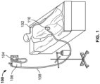
- FIG 1 shows a schematic view of a negative pressure wound therapy (NPWT) system 100 and a patient 102 having a wound (not shown in Figure 1 ).
- the NPWT system 100 includes an electronic vacuum regulator (EVR) 104, a canister 106, a tubing system 108, and a wound dressing 110.
- EMR electronic vacuum regulator
- NPWT can occur in a hospital setting or outside of the hospital with chronic wounds.
- the EVR 104 can include a controller (including one or more processors and memory) and a flow rate meter having one or more valves and sensors to measure and control the flow rate of liquid through the EVR 104 and/or the amount of negative pressure applied.
- the EVR 104 can include a pump or other device configured to produce negative pressure.
- the EVR 104 can be connected to a pump or other device configured to produce negative pressure, such as a wall vacuum source or a dedicated vacuum source.
- the wound dressing 110 can be configured to cover and substantially seal a wound of the patient 102.
- the tubing system 108 can include one or more hoses to connect the wound dressing 110, the canister 106, and the EVR 104 to apply negative pressure (a vacuum) to the wound of the patient 102.
- the canister 106 can collect liquid removed from the wound of the patient 102.
- the NWPT system 100 can be configured differently than as illustrated.
- one or more of the EVR 104, the canister 106, the tubing system 108, and the wound dressing 110 can be shaped and positioned differently than as illustrated.
- one or more components can be added, replaced, or removed from the NWPT system 100.
- the canister 106 can be replaced with a collection bag.
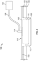
- Figure 2 is a schematic view of the NWPT system 100, including the EVR 104, the tubing system 108, and the wound dressing 110 (the canister 106 is omitted from Figure 2 ).
- the wound 112 is a relatively deep wound into the flesh of the patient 102.
- the wound 112 can be deep enough to extend through skin tissue 122, through fat tissue 124, and into muscle tissue or visceral spaces 126 of the patient 102. In other examples, the wound 112 can be deeper or less deep depending on the injury to the patient 102.
- the wound dressing 110 includes a tubing connector 114, a membrane 116, and a pad 118, such as a foam sponge pad, a gauze pad, or other type of wound filler.
- the pad 118 can be an open cell foam pad (commonly called a sponge) that is cut to size and placed in the wound 112.
- the membrane 116 can be a relatively thin membrane configured to substantially seal the wound 112.
- the tubing connector 114 can connect to the tubing system and extend through the membrane 116 to allow for the EVR 104 to apply negative pressure to the wound 112.
- the pad 118 can be porous to allow flow of liquid and gas between the tubing connector 114 and a surface of the wound 112.
- the membrane 116 can have an adhesive positioned around a perimeter of the membrane 116 that is configured to stick the membrane 116 to the patient 102 and seal the wound 112 well enough that the EVR 104 can suitably apply negative pressure to the wound 112 to promote new tissue growth.
- an additional barrier 120 can be added under the pad 118.
- the barrier 120 can be a separation layer that is positioned between the pad 118 and the surface of the wound 112 to space the pad 118 from the surface of the wound 112 and prevent or reduce tissue in-growth into pores of the pad 118.
- the tubing connector 114, the membrane 116, and the pad 118 can be part of a wound dressing 110 for a negative pressure wound therapy system that is intended to be delivered without the barrier 120 and is configured for use without the barrier 120.
- the wound dressing 110 can be intended to be used with the pad 118 placed into the wound 112 and covered by the membrane 116 without placing the barrier 120 under the pad 118.
- NPWT can be performed without the barrier 120, however, doing so can allow for tissue ingrowth into pores of the pad 118. Therefore, the barrier 120 can be provided separately as an additional structure to improve upon an existing wound dressing 110 where the pad 118 is a porous foam material that is susceptible to tissue ingrowth.
- the barrier can also be placed to provide protection from desiccation or drying out of susceptible structures such as tendons, nerves, blood vessels, and/or bone.
- the barrier can be coated with a lubricant such as Vaseline or even antimicrobials such as antibiotics, silver compounds or other materials such as growth factors or other chemicals or medications to promote tissue healing and/or prevent infection.
- the barrier 120 can be added as an additional structure in order to prevent or reduce in-growth of tissue (e.g. the muscle tissue or visceral organs 126) into pores of the pad 118.
- the barrier 120 can space the pad 118 from one or more tissues in order prevent or reduce contact with those tissues.
- the barrier 120 is positioned under the pad 118 and also wrapped at least partially around sides of the pad 118 to space the pad 118 from tissue.
- the barrier 120 is positioned between the pad 118 and the muscle tissue 126, but not necessarily between the pad 118 and the fat tissue 124 (the barrier 120 is shown adjacent to only part of the fat tissue 124) or the skin tissue 122.
- the barrier 120 can be larger or smaller and placed to cover more (e.g. covering all or part of each of the skin tissue 122, the fat tissue 124, and/or the muscle tissue 126) or fewer tissues as suitable for the application.
- the barrier 120 can be wrapped fully or partially around the pad 118, thereby fully or partially enclosing the pad 118.
- This particular embodiment would be most useful for deep tracts or tunnels in the wound, in which wound filler is often placed to apply NPWT and prevent loculation.
- These specific embodiments can have preferred shapes (i.e. cylindrical or rectangular) and dimensions for commonly treated deep wound tracts or tunnels.
- the advantage of these embodiments over traditional methods, is that the barrier can serve its innovative function of physically separating the wound filler from the wound tissue to prevent or reduce ingrowth in a more circumferential fashion in parts of the wound that have more than just a single planar surface that needs to heal.
- the barrier 120 can be a structure that is entirely separate from the pad 118, and it can be sold and provided separately for use with a version of the wound dressing 110 that was intended to be used without the barrier 120.
- the barrier 120 can be attached to the pad 118 and can be sold and delivered together (see, for example, the dressings 610, 710, and 810 described below with respect to Figures 15-18 ).
- the barrier 120 can be provided separately from the pad 118, yet be configured to be attached to the pad 118 such as by using one or more fasteners at the time of application of the dressing.
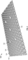
- Figure 3 is a perspective view of the barrier 120.
- Figure 4 is a top plan view of the barrier 120.
- Figure 5 is an enlarged perspective view of a portion of the barrier 120.
- the barrier 120 can include complex geometry configured to space tissue away from a porous pad 118 to reduce or prevent tissue ingrowth. Therefore, the barrier 120 provides a physical separation between the wound and the in-growth inducing surface of the wound filler.
- the barrier 120 can include a base layer 130 and structure extending from the base layer 130, such as walls 132 and posts 134.
- the walls 132 can define a repeating polygonal shape, such as the repeating hexagonal shape illustrated in Figure 3 . In other embodiments, the walls 132 can define a different repeating polygonal shape than as illustrated. In other embodiments, the walls 132 can define a different non-polygonal repeating shape, such as repeating circles. In other embodiments, the walls 132 can define different shapes as suitable for the application.
- the walls 132 and the posts 134 can extend substantially normally from the base layer 130 to impart thickness to the barrier 120.
- the posts 134 can be positioned substantially centrally in one, more than one, or all of spaces (or indentations) defined by the walls 132.
- the posts 134 can provide an offset to help keep tissue (i.e. the muscle tissue 126) or material (i.e. material of the pad 118) out of the spaces defined by the walls 132.
- the posts 134 can be omitted if the barrier is shaped and configured to suitably operate without the posts 134.
- the base layer 130 of the barrier 120 can define a plurality of perforations (or pores) 136 extending through the base layer 130.
- the base layer 130 can define one or more perforations 136 extending through the base layer 130 in each of the spaces defined by the walls 132 and can define perforations 136 extending through the base layer 130 at positions under the walls 132.
- the perforations 136 are the only passages extending entirely through the base layer 130.
- the base layer 130 includes three perforations 136 in each of the hexagonal spaces (or indentations) defined between the walls 132. In other embodiments, more or fewer than three perforations 136 can be positioned in each of the spaces defined between the walls 132.
- the base layer 130 also includes one perforation 136 extending through the base layer 130 at some of the intersections of the walls 132. As shown, the base layer 130 includes perforations 136 under roughly half of the intersections of the walls 132. In other embodiments, the base layer 130 can include more or fewer perforations 136 positioned under the walls 132 than as illustrated.
- the walls 132 can have a smaller height at portions 132A of the walls 132 that are positioned over perforations 136 and can have a taller height at portions 132B of the walls 132 that are connected to the base layer 130. This can allow for increased flow through perforations 136 that are positioned under the walls 132. This different in wall height also forms passages through the walls 132 that can facilitate flow laterally across the barrier 120.
- the barrier 120 can include one or more tabs 138 extending away from the base layer 130.
- the tabs 138 can be sized, shaped, and configured to allow for a user (e.g. a doctor or other medical provider) to pull on the tabs 138 to remove the barrier 120 from the wound 112.
- the tabs 138 can have a strength that is suitable to withstand the force of pulling on the tabs 138 without tearing after the barrier 120 has been left in the wound 112 for an extended period (e.g. several hours or several days). Additional embodiments include suture or wire that can extend outside the barrier 120 to enable or facilitate removal.
- the base layer 130 can be the bottom-most layer of the barrier 120 and be configured for a bottom surface 142 of the base layer 130 to be positioned adjacent the surface of the wound 112.
- the structure extending up from a top surface 140 of the base layer e.g. the walls 132 and the posts 134) can be positioned adjacent the porous material of the pad 118.
- the barrier 120 can space the pad 118 away from the wound 112 so as to prevent or reduce tissue ingrowth into the pad 118 without additional structure extending from a bottom side of the base layer 130.
- the barrier 120 can be manufactured as an integral component of the sponge pad or wound filler 118, such that the two elements are not separate, but one.
- Such a composite improved NPWT dressing could possess most commonly an open-cell foam sponge superficial surface (i.e. facing away from the wound), whose primary purpose would be to facilitate transmission of negative pressure to the wound and evacuation of wound fluids from the wound 112 surface.
- a barrier layer can be fixedly attached on a wound-facing surface of this composite dressing.
- Such a barrier layer can serve the same purpose as the barrier 120 does in other embodiments in which the barrier 120 is an independent and separate piece.
- Such a barrier would be a physical barrier intended to prevent or reduce tissue in-growth into the open-cell foam sponge or other wound filler material. In this way, this embodiment would not be an add on to current NPWT dressings, but rather a uniquely new NPWT dressing with enhanced capability over and above the current art.
- the barrier 120 can have structure extending from both of the top and bottom surfaces 140 and 142 of the base layer 130.
- the barrier 120 can have walls 132 and posts 134 extending from the bottom surface 142 that are substantially a mirror image to the walls 132 and the posts 134 extending from the top surface 140 (except that the tabs 138 can be omitted).
- the barrier 120 can have structure extending from the bottom surface 142 of the base layer 130 that is different than the structure extending from the top surface 140 of the base layer 130. Structure that extends from the top surface 140 can be sized, shaped, and configured to interface with the pad 118.
- Structure that extends from the bottom surface 142 can be sized, shaped, and configured to interface with the muscle tissue 126 or some other tissue of the patient 102 to prevent or resist the muscle tissue 126 from clogging the pores 136 when the muscle tissue 126 grows during the negative pressure wound therapy.
- the walls 132 can at least partially block at least some of the perforations 136 when viewed from the top (see, e.g., Figure 4 ).
- the barrier 120 includes structure (e.g. the walls 132) that at least partially block all of the perforations 136 that extend through the base layer 130. In such embodiments, all (or substantially all) of the perforations 136 are at least partially blocked to prevent or reduce tissue growth from extending through the barrier 120 to pores of the pad 118.
- the barrier 120 can be a one piece structure with complex geometry. Accordingly, the base layer 130, the walls 132, the posts 134, and the tabs 136 can be integrally formed as a single construct. Alternative designs can allow for the barrier 120 to have multiple layers and allow for removal of some layers to decrease the height of the barrier by the treating provider at the time of dressing application.
- the barrier 120 can be integrally formed by injection molding via a pliable medical grade polymer.
- the barrier 120 can be made of silicon or polyurethane. In other embodiments, the barrier 120 can be made of polydioxanone, or another material that is able to dissolve if left implanted in the patient 102 for many days.
- the barrier 120 can be constructed of biodegradable material and left in the wound 112 permanently.
- the barrier 120 can be clear, colored, or tinted to allow for easy identification within the wound 112 in order to prevent it from being left in the wound 112, for versions of the barrier 120 that are not biodegradable.
- a radiographic marker can be included in the barrier 120 to allow for identification by radiograph, as a means of preventing unintended retention of a dressing in a wound.
- the barrier 120 can be made of a transparent or translucent material. This can allow for better visualization of the wound 112 under the barrier 120.
- the barrier 120 can also be tinted (such as tinted purple, green, and/or blue) to increase visibility in the wound 112 so as to avoid or reduce the risk of the barrier 120 being undesirably left in the wound 112.
- the barrier 120 can be both tinted as well as transparent or translucent.
- the tabs 138 (or other removal handles) can be colored and some or all of other portions of the barrier 120 can be clear and not colored.
- the barrier 120 can be formed of a material and can be sized and shaped to be both somewhat pliable and somewhat shape-retaining.
- the barrier 120 can be pliable enough to bend to conform to a shape of a wound and/or to wrap at least partially around a sponge or other pad 118, such as shown schematically in Figure 2 .
- the barrier 120 can be rigid enough such that the structure (e.g. the walls 132 and posts 134) at least partially retain its shape when placed in the wound 112 under the pad 118 and negative pressure is applied to allow for flow through the barrier 120.
- the barrier 120 can be configured to be cut. Doctors or other medical personnel can cut the barrier 120 to shape so as to fit in the wound 112 depending on the shape of the wound 112. In some of such embodiments, the barrier 120 can also be rigid enough to be held in one hand and cut with the other hand without the barrier 120 sagging undesirably limp during the cutting process.
- the barrier 120 can be sized to be relatively long and wide as viewed from the top (see Figure 4 ) and to have a relatively thin thickness (or height) as viewed on-edge.
- the barrier 120 can have a length and width that are each several centimeters long and a thickness that is about 1 to 5 mm thick.
- the barrier 120 can have a thickness of 1 to 5 mm not including the tabs 138 such that the tabs 138 effectively increase the thickness of the barrier 120 to more than 1 to 5 mm.
- the barrier 120 can have a relatively high tensile strength so as to resist ripping when in tension.
- the perforations 136 can be sized large enough to allow for flow through the barrier 120 such that the NPWT system 100 functions effectively to apply negative pressure to the wound 112 below the barrier 120.
- the perforations 136 can each have a diameter of about 1 to 5 mm.
- the perforations 136 of the barrier 120 can be sized and shaped to allow for the sucking of liquid and exudate through the perforations 136 without clogging the perforations 136 (or with reduced clogging of the perforations 136).
- the walls 132 and/or the posts 134 can have a thickness (when viewed from the top as in Figure 4 ) that is small enough to allow the barrier 120 to be flexible and that is large enough to at least partially resist compression when the barrier 120 is placed under the pad 118 and negative pressure is applied.
- the walls 132 and/or the posts 134 can have a thickness (when viewed from the top as in Figure 4 ) of between 1 and 5 mm.
- the barrier 120 can include radiopaque material. Radiopaque material can help ensure that the barrier 120 is visible during x-ray imaging, which, can allow medical professionals to remove the barrier 120 from the patient 102 in the event that the barrier 120 is accidentally left inside the patent after the barrier 120 was supposed to be removed.
- the barrier 120 can include one or more radiopaque markers such as thin diameter wires (not shown) embedded within flexible, medical-grade polymer material that forms the barrier 120.
- a radiopaque thin diameter wire can be positioned in the barrier 120 at the one or more tabs 138 to both reinforce the tabs 138 and to help confirm removal using radiography.
- the wire or suture can also be used as "rebar" to reinforce the tensile strength of the barrier 120 and resist tearing. The wire or suture in this embodiment would typically be manufactured to lay within the walls of the barrier 120.
- the barrier 120 can include a coating.
- the barrier 120 can be coated with a lubricant. Coating with a lubricant can be beneficial in situations, such as, when used in wounds with exposed bone or tendon to help prevent (or resist) the bone or tendon from drying out.
- the barrier 120 can be coated with a bacteriostatic agent that is configured to stop or slow the reproduction of bacteria.
- the barrier 120 can be coated with an antibiotic coating.
- the barrier 120 can be coated with another coating that is deemed suitable for the application.
- the barrier 120 can include irrigation flow channels (e.g. see the irrigation channels of Figures 6 , 7A , and 7B ) extending through the barrier 120.
- irrigation flow channels can extend through the barrier 120 along a main trunk line flowing through a middle portion of the barrier 120 and with branch lines extending out from the trunk line.
- This type of dressing can support either simultaneous or alternating periods of irrigation and suction. If alternating between suction and irrigation, there can be periods of dwell time between periods spent irrigating or suctioning the wound.
- the barrier 120 could be trimmed in areas where there are branch lines while maintaining the inlet to the trunk line untrimmed. In embodiments that do not require irrigation, the barrier 120 need not include flow channels.
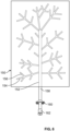
- FIG. 6 is a top view of a barrier 150 having irrigation channels 152, 154, and 156.
- the irrigation channel 152 can be a main trunk line from which the irrigation channels 154 branch off.
- the irrigation channels 156 can, in turn, branch off the irrigation channels 154.
- the irrigation channels 152, 154, and 156 can be oriented similar to the veins in a leaf where a central tube (e.g. the irrigation channel 152) branches into additional tubes (e.g. the irrigation channels 154 and/or 156) to cover the entire surface. This orientation can allow a tube 158 to enter from a side of the barrier 150 to supply irrigant to the barrier 150.
- a central tube e.g. the irrigation channel 152
- additional tubes e.g. the irrigation channels 154 and/or 156
- the tube can be positioned substantially normal and central to the non-wound facing surface of the barrier and the irrigation channels can extend radially from this tube.
- This tube can be long enough to extend through or more than through the common thickness of a wound filler, like foam sponge.
- a clamp 160 can be included on the tube 158 to clamp down and seal or restrict flow through the tube 158.
- the tube 158 can include a connector 162 for connecting to additional tubing (e.g. to the tubing system 108 described above with respect to Figures 1 and 2 ).
- the barrier 150 can be substantially similar to the barrier 120 described above except for the addition of the irrigation channels 152, 154, and 156.
- the barrier 150 can be used to supply irrigant to the wound (via the irrigation channels 152, 154, and 156), and simultaneously allow for negative pressure wound therapy, with liquid and exudate sucked through the perforations 136 (not shown in Figure 6 ). By allowing for negative pressure wound therapy simultaneously with irrigation, this can reduce or eliminate the need for a dwell time between irrigation and negative pressure wound therapy.
- the barrier 150 can have one or more different structures as suitable for the application as a barrier having irrigation channels.
- FIGS 7A and 7B are top and side views of a barrier 170 having irrigation channels 172 and 174.
- the irrigation channels 172 form multiple main trunk lines from which the irrigation channels 174 branch off.
- a tube 176 connects to the barrier 170 at a middle portion 178, and the irrigation channels 172 extend radially outward from the middle portion 178. Accordingly, this alternate orientation of the barrier 170 would allow for the tube 176 to be run outside of the barrier 170 (above it) and allow radial tubes (the irrigation channels 172) to be designed to take the irrigation towards a periphery of the barrier 170.
- the irrigation channels 174 can terminate at outlets 180 that are positioned on a bottom surface of the barrier 170 and/or at the periphery of the barrier 170.
- outlets 180 can be positioned proximate a perimeter of the barrier 170 so as to irrigate tissue near the perimeter of the barrier 170 and some of the outlets 180 can be positioned closer to a center of the barrier 170 so as to irrigate tissue near the center of the barrier 170.
- the barrier 170 can have irrigation channels that are different than those illustrated.
- the barriers 150 and 170 can have features (e.g. walls 132, posts 134, and/or perforations 136) and uses that are the same or similar to those described herein for the barrier 120.
- one of the barriers 150 or 170 can be used in a manner similar to the barrier 120 as described above for Figure 2 , with the barrier 150 or 170 added as an additional structure in order to prevent or reduce in-growth of tissue (e.g. the muscle tissue or visceral organs 126) into pores of the pad 118.
- the barrier 150 or 170 can be a structure that is entirely separate from the pad 118, and it can be sold and provided separately for use with a version of the wound dressing 110 that was intended to be used without the barrier 150 or 170.
- the barrier 150 or 170 can be attached to the pad 118 and can be sold and delivered together (see, for example, the dressings 610, 710, and 810 described below with respect to Figures 15-18 ).
- the barrier 150 and 170 can be provided separately from the pad 118, yet be configured to be attached to the pad 118 such as by using one or more fasteners at the time of application of the dressing.
- the barriers 150 and 170 can be configured to be trimmed (e.g. via scissors) to substantially match the size of the wound 112 and still function to supply irrigant to the surface of the wound 112.
- the tube 158 is attached to the barrier 150 along one edge.
- the barrier 150 can be trimmed down to size by trimming the other three edges while maintaining the structural integrity of the connection between the tube 158 and the barrier 150.
- one or more of the channels 154 and 156 can be cut and yet the barrier 150 can still function to supply irrigant to the surface of the wound 112 through those portions of the channels 154 and 156 that remain.
- the tube 176 is attached to the barrier 160 at the middle portion 178. Accordingly, the barrier 170 can be trimmed down to size by trimming any of the four edges while maintaining the structural integrity of the connection between the tube 176 and the barrier 170 at the middle portion 178. During trimming, one or more of the channels 172 and 174 can be cut and yet the barrier 170 can still function to supply irrigant to the surface of the wound 112 through those portions of the channels 172 and 174 that remain.
- the barrier 120 (as well as the barriers 150 and 170) can include filaments that act to reinforce the integrity of the barrier 120 in a manner that is similar to rebar in concrete.
- Such filaments can be in the form of suture material, a metal, a fabric, and/or a stronger polymer.
- the filaments can be high tensile material that helps resist or prevent portions of the barrier 120 being fragmented and retained in the wound 112.
- the filaments can be in a central portion of the barrier 120 in plane with the barrier 120, such that the filaments are in-line to transect or follow the margins of the perforations 136.
- the filaments can also be in a random pattern to allow for improved tensile strength without being too bulky.
- the filaments can be in the form of a mesh layer that is embedded in the barrier 120 prior to the barrier 120 being perforated.
- a perforating tool can cut a hole in the barrier 120, and also in the mesh filaments imbedded in the barrier 120.
- the mesh filaments can optionally be positioned in order to prevent or reduce overlap across the perforations 136.
- These filaments can optionally traverse the perforations 136. If the filaments do traverse the perforations 136, the filaments can serve as a sieve to prevent tissue in-growth yet permit the evacuation of wound fluids.
- the barrier 120 can be formed as a flat woven mesh layer or a three dimensional mesh structure (such as a pot scrubber or loofah) dipped or coated in silicone or similar material that is bio-compatible/inert.
- a mesh structure could also be similar to a honeycomb type structure.
- the mesh structure can offer tensile strength and compressibility.
- the mesh structure can be constructed of suture, metal, polymer, or fabric material.
- the mesh structure can form a core material that offers tensile strength and that is coated to prevent or reduce tissue ingrowth. Constructing the barrier 120 in this manner can allow for a compressible structure with significant fluid pathways to allow irrigation passage as well as transmit negative pressure.
- the barrier 120 can have a structure that is constructed of transparent coating over thin filaments (such as a PDS, proline, monocryl, or woven polyester such as ethibond, fiberwire, or vycryl).
- the barrier 120 can be made of non-dissolvable or dissolvable material.
- the barrier 120 can include a dissolvable polyglycolate material.
- the barrier 120 can include collagen based materials to create structural support but still allow a fully dissolvable barrier 120.
- the barrier 120 can also be used with any suitable system as a sponge, pad, or wound filler replacement. By removing the pad 118 (or any other wound filler) and using the barrier 120, the clinician can see the wound 112 assuming the barrier 120 is constructed of a clear material. The tabs 138 can be trimmed to allow for easier sealing over the barrier 120.
- the barrier 120 can be used with any suitable system that incorporates a sealing layer102 and suction tubing 108.
- Figure 6 is an example method 200 of using the NPWT system 100.
- the wound 112 of the patient 102 is prepared. This can include cleaning the wound 112, removing necrotic tissue, and/or other procedures deemed necessary or desirable.
- the wound dressing 110 is provided.
- the wound dressing 110 can include the tubing connector 114, the membrane 116, and the pad 118 (such as a sponge or other filling material).
- the wound dressing 110 can be intended to be used, and can be suitable to be used, without an additional barrier (such as the barrier 120). However, adding the wound dressing 110 can be beneficially added as described below in steps 208 and 210.
- the wound dressing 110 is prepared. Components of the wound dressing 110 can be removed from packaging, assembled, and/or trimmed. For example, the pad 118 can be trimmed to a size and shape suitable for being positioned in the wound 112 of the patient 102.
- the wound dressing 110 can now ready to be applied to the wound 112, except when it is deemed desirable to use the barrier 120. If the wound dressing 110 is to be used without the dressing 112, the method 200 can proceed to step 214. If the benefits of the barrier 120 are desired, steps 208, 210, and 212 can be performed.
- the barrier 120 is provided.
- the barrier 120 can be intended for use with the wound dressing 110 and similar wound dressings to improve treatment of the patient 102, yet the barrier 120 is provided separately from the wound dressing 110.
- the barrier 120 is prepared.
- the barrier 120 can be removed from packaging. In embodiments where the barrier 120 is a single, integrally formed barrier, no assembly is needed.
- the barrier can be trimmed to a size and shape suitable for being positioned in the wound 112 under the pad 118 to separate the pores of the pad 118 from some or all of the surface of the wound 112.
- the barrier 120 can be positioned in the wound.
- the barrier 120 can be positioned to substantially cover all (or substantially all) of the surface of wound tissue.
- the barrier 120 can be positioned to cover only a portion of the tissue in the wound, such as the muscle tissue 126. Covering the muscle tissue 126 can be beneficial because the muscle tissue 126 can tend to grow into the pores of spongey material like the pad 118, and consequently, pain and tissue damage can result when the pad 118 is removed from the wound 112 when such tissue ingrowth occurs.
- Other tissue, such as fatty tissue 124 can be less prone to ingrowth, and consequently, it can be less important to cover such fatty tissue 124 in such circumstances. Nonetheless, the fatty tissue 124 and other tissue can also be covered by the barrier 120.
- the wound dressing 110 can be applied.
- the pad 118 can be placed in the wound 112 on top of the barrier 120 and the membrane 116 can be applied to cover the wound 112.
- the tubing connector 114 can be applied so as to connect to tubing for applying NPWT.
- negative pressure wound therapy can be applied to the wound 112.
- the EVR 104 can work in conjunction with a vacuum source to apply negative pressure to the wound 112 in order to aid in healing.
- the wound dressing 110 When the wound dressing 110 is applied without the barrier 120, the wound dressing 110 can be used for a period of 24-72 hours or less. Even when removed within 24-72 hours or less, tissue ingrowth can occur potentially causing pain, tissue damage, and breakage of portions of the spongy material of the pad 118 and remaining in the wound 112 when the pad 118 is pulled out of the wound 112.
- the wound dressing 110 When the wound dressing 110 is applied with the barrier 120 positioned under the pad 118, pain, tissue damage, and/or breakage can be reduced. In some applications, the wound dressing 110 and the barrier 120 can be left in for longer than 24-72 hours because the barrier 120 can inhibit tissue ingrowth. Accordingly, use of the barrier 120 can increase the effective life and duration of each wound dressing 110.
- FIGS 9A-9B show perspective views of a wound dressing 300 for NPWT and a barrier 306 for use in the wound dressing 300.
- the wound dressing 300 can be suitable for use with relatively long (or deep) and narrow wounds, such as gunshot wounds and/or cutaneous fistulas.
- the wound dressing 300 can include a membrane 302, a pad 304, and the barrier 306.
- the barrier 306 can be wrapped substantially or entirely around a circumference of the pad 304.
- An irrigation tube (or lumen) 308 can be used to supply irrigation to the wound dressing 300.
- a suction tube (or lumen) 310 can be used to apply negative pressure to the wound dressing 300.
- components and features of the wound dressing 300 can be similar to those described above (e.g. for wound dressing 110) and also have some differences suitable for use in treating relatively long and narrow wounds.
- the pad 304 can be a foam pad (e.g. a foam sponge) like that described above for the pad 118, except the pad 304 is long and narrow.
- the barrier 306 can have features similar to barriers described above.
- some embodiments of the barrier 306 can be a porous barrier (similar to the barrier 120) that provides physical separation between the wound and an in-growth inducing surface of the pad 304.
- the barrier 306 can include irrigation channels similar to the barrier 150 or the barrier 170.
- the barrier 306 can be substantially nail-shaped, with a relatively broad and flat connection (or head) portion 312 and a relatively long and narrow cylinder (or shaft) portion 314.
- the barrier 306 defines a relatively long and narrow hollow central core 316.
- the cylinder portion 314 can be porous to allow fluid flow through the cylinder portion 314 into the central core 316 during NPWT.
- the cylinder portion 314 can prevent tissue ingrowth into the pad 304 in the central core 316.
- the barrier 306 can be perforated silicone or other suitable material.
- the barrier 306 can have a geometric structure, such as a honeycomb shaped structure similar to what is shown in Figure 3 .
- Figures 10A-10D show a series of steps for trimming the dressing 300.
- the dressing 300 can be trimmed by cutting through the barrier 306, and possibly the pad 304 as well (e.g. trimming with a knife or scissors).
- the dressing 300 can be manufactured to a size that is longer than a depth of the wound to be treated, and then be cut to a length that is deemed appropriate for the depth of the wound.
- the pad 304 can be exposed at a tip of the dressing 300, uncovered by the barrier 306 after being cut. Accordingly, risk of tissue ingrowth can be increased at the tip of the dressing 300 where the pad 304 is uncovered by the barrier 306 due to being cut.
- the dressing 300 can include a gap 318 at the distal end of the dressing 300 where the barrier 306 extends further than the pad 304.
- Figures 11A-11B show steps for closing the dressing 300 after being cut, such as by suturing.
- a distal end of the barrier 306 can have an opening 320 after being cut.
- the dressing 300 can be sized and shaped such that the barrier 306 can prevent or reduce the risk of tissue ingrowth into the pad 304 even without the opening 320 being closed.
- the dressing 300 can benefit from being closed after being cut to size.
- the opening 320 can be closed, such as by suturing.
- the opening 320 can be sutured closed via a vessel loop 322.
- the opening 320 can be closed by a silicone bond or other suitable mechanism.
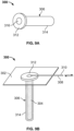
- FIG. 12 is a schematic view of the dressing 300 with the barrier 306 that is substantially shaped like a nail.
- the barrier 306 can have the flat connection (or head) portion 312 and the relatively long and narrow cylinder (or shaft) portion 314.
- Figure 13 shows a schematic view of a dressing 400 with a barrier 406 that is substantially shaped like a funnel.
- the barrier 406 can have a connection portion 412 that is substantially frustoconical and a cylinder portion 414 (similar to the cylinder portion 314) extending from a narrow end of the connection portion 412.
- Figure 14 shows a schematic view of a dressing 500 with a barrier 506 that is substantially shaped like a kettle.
- the barrier 506 can have a connection portion 512 that is relatively wide and flat much like the connection portion 312 of the barrier 306.
- the barrier 506 can have a shaft portion 514 that is rounded or bulging as compared to the cylinder portion 314 and the cylinder portion 414. Accordingly, Figures 12-14 show some of the various shapes suitable for treating relatively deep wounds.
- the barriers 306, 406, and 506 can be used with a pad (e.g. the pad 304 which can be a foam sponge) positioned inside the barriers 306, 406, and 506. In other embodiments, the barriers 306, 406, and 506 can be used without any pad or similar structure positioned inside the barriers 306, 406, and 506.
- a pad e.g. the pad 304 which can be a foam sponge
- the barriers 306, 406, and 506 can be used without any pad or similar structure positioned inside the barriers 306, 406, and 506.
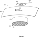
- Figure 15 is a perspective view of a dressing 610 having a combined pad 618 (such as a sponge) and barrier 620.
- the barrier 620 can be attached or attachable to the pad 618.
- the pad 618 can have a thickness of 1-20 mm and the barrier can have a thickness of 1-4 mm.
- the barrier 620 and the pad 618 can have some, all, or none of the features described above with respect to other examples of barriers and pads.
- the barrier 620 can include perforations 136.
- the barrier 620 and the pad 618 can be combined and sold together, with the barrier 620 attached to the pad 618. In such embodiments, the user need not assemble the barrier 620 and the pad 618.
- the barrier 620 and the pad 618 can be sized to fit in a given wound or can be configured to be trimmed together to a size suitable for a given wound (e.g. a user can cut both the barrier 620 and the pad 618 to an appropriate size using scissors while the barrier 620 is attached to the pad 618).
- the dressing 610 can include a tubing system 608, a membrane 616, and an adhesive connection layer 624 (e.g. a "lily pad").
- the membrane 616 can be positioned over the combined pad 618 and the barrier 620 to cover and seal the pad 618 and the barrier 620 in a wound.
- a hole 626 can be cut in the membrane 616 at a location aligned with the pad 618 and the adhesive connection layer 624 can be adhered to the membrane 616 at the hole 626 to connect the tubing system 608 to the hole 626 to provide suction to the dressing 610 and the corresponding wound.
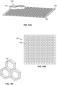
- Figures 16A-16C are views of features of the barrier 620.
- Figure 16A shows the barrier 620 having the base layer 130 with a plurality of perforations 136.
- a plurality of walls 132 can be positioned above (and/or extend from) the base layer 130 to form a honeycomb or other geometric shape. While Figure 16A shows the barrier 620 having only two honeycomb structures, the barrier 620 can include more honeycomb (or other shaped) structures repeating over some, most, or all of the base layer 130 (see, e.g. Figures 3-5 ). In some embodiments, the barrier 620 can have a combined thickness of the base layer 130 and the walls 132 of 1-5 mm.
- Figure 16B shows a view of the base layer 130 and its perforations 136.
- Figure 16C shows a view of the walls 132 forming three honeycomb structures.
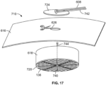
- FIG 17 is a perspective view of a dressing 710 having a combined pad 618 (such as a sponge) and barrier 720 with irrigation tubing 740.
- the dressing 710 can be similar to the dressing 610 (shown in Figure 15 ) except the dressing 710 includes irrigation tubing 740.
- An irrigation supply tube 742 can be connected to an adhesive connection layer 624 (e.g. a "lily pad") that has connections for both the irrigation supply tube 742 and the tubing system 608 (for providing suction).
- An extension irrigation tube 744 can extend through the pad 618, connecting the irrigation supply tube 742 to the irrigation tubing 740 in the barrier 720.
- the irrigation tubing 740 in the barrier 720 can extend radially outward to supply irrigant to a perimeter of the barrier 720. Suction applied via the tubing system 608 can draw irrigant and exudate from the wound up through the perforations 136, through the pad 618, through the adhesive connection layer 724, and out through the tubing system 608.
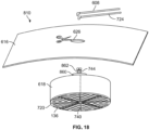
- FIG 18 is a perspective view of a dressing 810 having a combined pad 618 (such as a sponge) and barrier 720 with a suction manifold 860 and irrigation tubing 740.
- the dressing 810 can be similar to the dressing 610 (shown in Figure 17 ) except the dressing 810 includes the suction manifold 860.
- An extension suction tube 862 can connect the suction manifold 860 to the tubing system 608.
- the suction manifold 860 can be positioned on top of the pad 618 to distribute the suction force over an area on top of the pad 618. Fluid can flow into the suction manifold 860 through a bottom surface of the suction manifold 860 that is either open or substantially open. Fluid can flow out of the suction manifold 860 through a hole in the top of the suction manifold 860 where the extension suction tube 862 is connected to the suction manifold 860.
Landscapes
- Health & Medical Sciences (AREA)
- Heart & Thoracic Surgery (AREA)
- Public Health (AREA)
- Biomedical Technology (AREA)
- Vascular Medicine (AREA)
- Life Sciences & Earth Sciences (AREA)
- Animal Behavior & Ethology (AREA)
- General Health & Medical Sciences (AREA)
- Engineering & Computer Science (AREA)
- Veterinary Medicine (AREA)
- Hematology (AREA)
- Anesthesiology (AREA)
- Oral & Maxillofacial Surgery (AREA)
- Pulmonology (AREA)
- Surgery (AREA)
- Media Introduction/Drainage Providing Device (AREA)
- Materials For Medical Uses (AREA)
- Prostheses (AREA)
- Surgical Instruments (AREA)
Applications Claiming Priority (3)
| Application Number | Priority Date | Filing Date | Title |
|---|---|---|---|
| US16/749,511 US11160917B2 (en) | 2020-01-22 | 2020-01-22 | Negative pressure wound therapy barrier |
| EP21743873.8A EP4054496B1 (de) | 2020-01-22 | 2021-01-22 | Barriere für unterdruckwundtherapie |
| PCT/US2021/014608 WO2021150886A1 (en) | 2020-01-22 | 2021-01-22 | Negative pressure wound therapy barrier |
Related Parent Applications (1)
| Application Number | Title | Priority Date | Filing Date |
|---|---|---|---|
| EP21743873.8A Division EP4054496B1 (de) | 2020-01-22 | 2021-01-22 | Barriere für unterdruckwundtherapie |
Publications (2)
| Publication Number | Publication Date |
|---|---|
| EP4516278A2 true EP4516278A2 (de) | 2025-03-05 |
| EP4516278A3 EP4516278A3 (de) | 2025-04-16 |
Family
ID=76856546
Family Applications (2)
| Application Number | Title | Priority Date | Filing Date |
|---|---|---|---|
| EP25152724.8A Pending EP4516278A3 (de) | 2020-01-22 | 2021-01-22 | Barriere für unterdruckwundtherapie |
| EP21743873.8A Active EP4054496B1 (de) | 2020-01-22 | 2021-01-22 | Barriere für unterdruckwundtherapie |
Family Applications After (1)
| Application Number | Title | Priority Date | Filing Date |
|---|---|---|---|
| EP21743873.8A Active EP4054496B1 (de) | 2020-01-22 | 2021-01-22 | Barriere für unterdruckwundtherapie |
Country Status (5)
| Country | Link |
|---|---|
| US (4) | US11160917B2 (de) |
| EP (2) | EP4516278A3 (de) |
| AU (1) | AU2021211708B2 (de) |
| CA (1) | CA3160426A1 (de) |
| WO (1) | WO2021150886A1 (de) |
Families Citing this family (3)
| Publication number | Priority date | Publication date | Assignee | Title |
|---|---|---|---|---|
| US11160917B2 (en) * | 2020-01-22 | 2021-11-02 | J&M Shuler Medical Inc. | Negative pressure wound therapy barrier |
| US20240374434A1 (en) * | 2021-09-07 | 2024-11-14 | Kci Manufacturing Unlimited Company | Negative pressure dressing with differential collapsing force for wound closure |
| EP4338661B1 (de) * | 2022-09-19 | 2025-04-23 | Ivoclar Vivadent AG | Vakuumfolie zum scannen einer mundhöhle |
Family Cites Families (350)
| Publication number | Priority date | Publication date | Assignee | Title |
|---|---|---|---|---|
| US1000001A (en) | 1908-11-09 | 1911-08-08 | Robert A C Holz | Vacuum apparatus for hyperemic treatments. |
| US1385346A (en) | 1919-06-27 | 1921-07-19 | Taylor Walter Herbert | Surgical wound-dam |
| US1355846A (en) | 1920-02-06 | 1920-10-19 | David A Rannells | Medical appliance |
| US1596754A (en) | 1923-10-30 | 1926-08-17 | Judson D Moschelle | Reenforced tubing |
| US1936129A (en) | 1931-12-01 | 1933-11-21 | Andrew J Fisk | Method of treating the skin and device therefor |
| US2221758A (en) | 1937-05-12 | 1940-11-19 | Elmquist Francis | Surgical dressing |
| US2195771A (en) | 1937-11-09 | 1940-04-02 | Estler Louis Edmond | Surgical suction drainage cup |
| US2338339A (en) | 1940-11-08 | 1944-01-04 | Mere | Massaging vibrator |
| US2443481A (en) | 1942-10-19 | 1948-06-15 | Sene Leon Paul | Device for the treatment of wounds and the like lesions |
| US2573791A (en) | 1947-04-19 | 1951-11-06 | John N M Howells | Heat applying bandage |
| US2577945A (en) | 1947-12-06 | 1951-12-11 | Atherton Harold Starr | Plaster or bandage for skin application |
| US2632443A (en) | 1949-04-18 | 1953-03-24 | Eleanor P Lesher | Surgical dressing |
| US2682873A (en) | 1952-07-30 | 1954-07-06 | Johnson & Johnson | General purpose protective dressing |
| US3026874A (en) | 1959-11-06 | 1962-03-27 | Robert C Stevens | Wound shield |
| US3315665A (en) | 1963-10-11 | 1967-04-25 | Norman A Macleod | Method and apparatus for therapy of skin tissue |
| US3292619A (en) * | 1963-12-06 | 1966-12-20 | Kendall & Co | Absorbent dressing |
| US3382867A (en) | 1965-03-22 | 1968-05-14 | Ruby L. Reaves | Body portion developing device with combined vacuum and vibrating means |
| US3367332A (en) | 1965-08-27 | 1968-02-06 | Gen Electric | Product and process for establishing a sterile area of skin |
| US3520300A (en) | 1967-03-15 | 1970-07-14 | Amp Inc | Surgical sponge and suction device |
| US3528416A (en) | 1967-11-06 | 1970-09-15 | Lawrence J Chamberlain | Protective bandage |
| US3568675A (en) | 1968-08-30 | 1971-03-09 | Clyde B Harvey | Fistula and penetrating wound dressing |
| US3599830A (en) | 1969-06-23 | 1971-08-17 | Truly Magic Products Inc | Article dispenser operable without the use of hands |
| US3610238A (en) | 1970-04-28 | 1971-10-05 | Us Health Education & Welfare | Wound infection prevention device |
| BE789293Q (fr) | 1970-12-07 | 1973-01-15 | Parke Davis & Co | Pansement medico-chirugical pour brulures et lesions analogues |
| US3782377A (en) | 1971-09-07 | 1974-01-01 | Illinois Tool Works | Sterile plastic shield |
| US3814095A (en) | 1972-03-24 | 1974-06-04 | H Lubens | Occlusively applied anesthetic patch |
| US3812972A (en) | 1972-05-02 | 1974-05-28 | J Rosenblum | Liquid filter and method for fabricating same |
| US3874387A (en) | 1972-07-05 | 1975-04-01 | Pasquale P Barbieri | Valved hemostatic pressure cap |
| US3831588A (en) | 1972-10-16 | 1974-08-27 | Device Res Inc | Pressure sensing device |
| US3954105A (en) | 1973-10-01 | 1976-05-04 | Hollister Incorporated | Drainage system for incisions or wounds in the body of an animal |
| US3903882A (en) | 1974-04-19 | 1975-09-09 | American Cyanamid Co | Composite dressing |
| US3935863A (en) | 1974-07-19 | 1976-02-03 | Kliger Herbert L | Surgical sponge |
| US4191204A (en) | 1975-04-14 | 1980-03-04 | International Paper Company | Pressure responsive fluid collection system |
| US4058123A (en) | 1975-10-01 | 1977-11-15 | International Paper Company | Combined irrigator and evacuator for closed wounds |
| US4080970A (en) | 1976-11-17 | 1978-03-28 | Miller Thomas J | Post-operative combination dressing and internal drain tube with external shield and tube connector |
| US4139004A (en) | 1977-02-17 | 1979-02-13 | Gonzalez Jr Harry | Bandage apparatus for treating burns |
| US4178974A (en) | 1977-08-29 | 1979-12-18 | Rca Corporation | Flow controller |
| US4149541A (en) | 1977-10-06 | 1979-04-17 | Moore-Perk Corporation | Fluid circulating pad |
| US4224941A (en) | 1978-11-15 | 1980-09-30 | Stivala Oscar G | Hyperbaric treatment apparatus |
| SE414994B (sv) | 1978-11-28 | 1980-09-01 | Landstingens Inkopscentral | Venkateterforband |
| WO1980001139A1 (en) | 1978-12-06 | 1980-06-12 | Svedman Paul | Device for treating tissues,for example skin |
| US4250882A (en) | 1979-01-26 | 1981-02-17 | Medical Dynamics, Inc. | Wound drainage device |
| US4399816A (en) | 1980-03-17 | 1983-08-23 | Spangler George M | Wound protector with transparent cover |
| US5445604A (en) | 1980-05-22 | 1995-08-29 | Smith & Nephew Associated Companies, Ltd. | Wound dressing with conformable elastomeric wound contact layer |
| US4297995A (en) | 1980-06-03 | 1981-11-03 | Key Pharmaceuticals, Inc. | Bandage containing attachment post |
| US4460354A (en) | 1980-07-08 | 1984-07-17 | Snyder Laboratories, Inc. | Closed wound suction evacuator |
| US4341209A (en) | 1981-01-12 | 1982-07-27 | The Kendall Company | Adhesive bandage with foam backing |
| NZ199684A (en) | 1981-02-13 | 1985-03-20 | Smith & Nephew Ass | Wound dressing;wound facing layer a conformable elastomeric integral net |
| US4457755A (en) | 1981-04-02 | 1984-07-03 | Wilson John D | Surgical `in-line` evacuator |
| US4373519A (en) | 1981-06-26 | 1983-02-15 | Minnesota Mining And Manufacturing Company | Composite wound dressing |
| SE429197B (sv) | 1981-10-14 | 1983-08-22 | Frese Nielsen | Anordning for behandling av sar |
| US4460370A (en) | 1981-10-29 | 1984-07-17 | Almedco, Inc. | Trans-dermal medication application cell |
| US4465062A (en) | 1982-05-14 | 1984-08-14 | Gina Versaggi | Noninvasive seal for a sucking chest wound |
| US4469092A (en) | 1982-09-27 | 1984-09-04 | Marshall Walter D | Scalp stimulating system |
| DE3321151C2 (de) | 1983-06-11 | 1986-09-18 | Walter Küsnacht Beck | Vorrichtung zum Absaugen von Sekreten |
| US4778446A (en) | 1983-07-14 | 1988-10-18 | Squibb & Sons Inc | Wound irrigation and/or drainage device |
| US4624656A (en) | 1983-07-25 | 1986-11-25 | Hospitak, Inc. | Hyperbaric gas treatment device |
| US4559035A (en) | 1983-09-26 | 1985-12-17 | Snyder Laboratories, Inc. | Collapsible wound suction evacuator |
| US4897081A (en) | 1984-05-25 | 1990-01-30 | Thermedics Inc. | Percutaneous access device |
| GB8419745D0 (en) | 1984-08-02 | 1984-09-05 | Smith & Nephew Ass | Wound dressing |
| US4872450A (en) | 1984-08-17 | 1989-10-10 | Austad Eric D | Wound dressing and method of forming same |
| US4679590A (en) | 1984-08-31 | 1987-07-14 | Hergenroeder Patrick T | Receptacle for collecting fluids |
| US4740202A (en) | 1984-10-12 | 1988-04-26 | Haemonetics Corporation | Suction collection device |
| US4655754A (en) | 1984-11-09 | 1987-04-07 | Stryker Corporation | Vacuum wound drainage system and lipids baffle therefor |
| US4664652A (en) | 1985-02-07 | 1987-05-12 | Snyder Laboratories, Inc. | Wound evacuator |
| US4717382A (en) | 1985-04-18 | 1988-01-05 | Emergency Management Products, Inc. | Noninvasive apparatus for treating a sucking chest wound |
| US4637819A (en) | 1985-05-31 | 1987-01-20 | The Procter & Gamble Company | Macroscopically expanded three-dimensional polymeric web for transmitting both dynamically deposited and statically contacted fluids from one surface to the other |
| GB2176402B (en) | 1985-06-20 | 1989-04-19 | Craig Med Prod Ltd | Wound management appliance for use on the human skin |
| US4633863A (en) | 1985-09-27 | 1987-01-06 | Filips Chester P | Arterial anchor bandage |
| US4733659A (en) | 1986-01-17 | 1988-03-29 | Seton Company | Foam bandage |
| US4667666A (en) | 1986-04-18 | 1987-05-26 | Alice Fryslie | Protective bandaging device |
| CH670049A5 (de) | 1986-04-24 | 1989-05-12 | Vebo | |
| US4641643A (en) | 1986-04-28 | 1987-02-10 | Greer Leland H | Resealing skin bandage |
| GB8620227D0 (en) | 1986-08-20 | 1986-10-01 | Smith & Nephew Ass | Wound dressing |
| US4743232A (en) | 1986-10-06 | 1988-05-10 | The Clinipad Corporation | Package assembly for plastic film bandage |
| DE3751254D1 (de) | 1986-10-31 | 1995-05-24 | Nippon Zeon Co | Wundverband. |
| US4759354A (en) | 1986-11-26 | 1988-07-26 | The Kendall Company | Wound dressing |
| JPS63135179A (ja) | 1986-11-26 | 1988-06-07 | 立花 俊郎 | 薬物の経皮投与具 |
| US4886502A (en) | 1986-12-09 | 1989-12-12 | Thermedics, Inc. | Peritoneal access catheter |
| US4820265A (en) | 1986-12-16 | 1989-04-11 | Minnesota Mining And Manufacturing Company | Tubing set |
| DE3880129D1 (de) | 1987-01-20 | 1993-05-13 | Medinorm Ag | Vorrichtung zum absaugen von wundfluessigkeiten. |
| US4962761A (en) | 1987-02-24 | 1990-10-16 | Golden Theodore A | Thermal bandage |
| GB8706116D0 (en) | 1987-03-14 | 1987-04-15 | Smith & Nephew Ass | Adhesive dressings |
| US4778456A (en) | 1987-04-03 | 1988-10-18 | Oddvin Lokken | Method of sterilizing an operating field and sterilized cassette therefor |
| US4765316A (en) | 1987-04-20 | 1988-08-23 | Marshall Walter D | Scalp stimulator |
| US4747166A (en) | 1987-05-15 | 1988-05-31 | Kuntz David H | Fluid aspiration system for the management of urinary incontinence |
| ATE59303T1 (de) | 1987-06-22 | 1991-01-15 | Takeda Chemical Industries Ltd | Saugeinrichtung fuer medizinische operation. |
| US5002529A (en) | 1987-07-10 | 1991-03-26 | Solco Basle, Inc. | Postoperative wound drainage |
| FR2618337B1 (fr) | 1987-07-22 | 1989-12-15 | Dow Corning Sa | Pansement chirurgical et procede pour le fabriquer |
| US4930997A (en) | 1987-08-19 | 1990-06-05 | Bennett Alan N | Portable medical suction device |
| US4915694A (en) | 1987-10-02 | 1990-04-10 | Vitaphore Corporation | Antimicrobial wound dressing and skin fixator for percutaneous conduits |
| US5176663A (en) | 1987-12-02 | 1993-01-05 | Pal Svedman | Dressing having pad with compressibility limiting elements |
| US4906240A (en) | 1988-02-01 | 1990-03-06 | Matrix Medica, Inc. | Adhesive-faced porous absorbent sheet and method of making same |
| US4834110A (en) | 1988-02-01 | 1989-05-30 | Richard Patricia A | Suction clamped treatment cup saliva sampler |
| JPH0228713A (ja) | 1988-04-26 | 1990-01-30 | Mitsubishi Electric Corp | 信号取得装置及び方法 |
| US4921492A (en) | 1988-05-31 | 1990-05-01 | Laser Technologies Group, Inc. | End effector for surgical plume evacuator |
| US4917112A (en) | 1988-08-22 | 1990-04-17 | Kalt Medical Corp. | Universal bandage with transparent dressing |
| US5003971A (en) | 1988-09-02 | 1991-04-02 | Buckley John T | Expansion system for a medical and surgical dressing |
| US5215539A (en) | 1988-10-12 | 1993-06-01 | Schoolman Scientific Corporation | Vacuum strip apparatus for surgery |
| FR2639234B1 (fr) | 1988-11-21 | 1994-05-06 | Denance Raymond | Dispositif d'injection a usage medical et veterinaire dont la mire stabilisatrice est a usage unique et actionne un moyen faisant office de clapet au niveau de l'aiguille |
| US4969880A (en) | 1989-04-03 | 1990-11-13 | Zamierowski David S | Wound dressing and treatment method |
| US5261893A (en) | 1989-04-03 | 1993-11-16 | Zamierowski David S | Fastening system and method |
| US5527293A (en) | 1989-04-03 | 1996-06-18 | Kinetic Concepts, Inc. | Fastening system and method |
| US5100396A (en) | 1989-04-03 | 1992-03-31 | Zamierowski David S | Fluidic connection system and method |
| US5086764A (en) | 1989-04-13 | 1992-02-11 | Thomas Gilman | Absorbent dressing |
| US5106362A (en) | 1989-04-13 | 1992-04-21 | The Kendall Company | Vented absorbent dressing |
| US5139023A (en) | 1989-06-02 | 1992-08-18 | Theratech Inc. | Apparatus and method for noninvasive blood glucose monitoring |
| JP2719671B2 (ja) | 1989-07-11 | 1998-02-25 | 日本ゼオン株式会社 | 創傷被覆材 |
| US5358494A (en) | 1989-07-11 | 1994-10-25 | Svedman Paul | Irrigation dressing |
| US5042978A (en) | 1989-08-08 | 1991-08-27 | Eastman Kodak Company | Container using a mass of porous material for liquid retention |
| JPH0336640U (de) | 1989-08-23 | 1991-04-10 | ||
| US4988336A (en) | 1989-09-22 | 1991-01-29 | Allied Healthcare Products, Inc. | Electronic suction regulator |
| US5106629A (en) | 1989-10-20 | 1992-04-21 | Ndm Acquisition Corp. | Transparent hydrogel wound dressing |
| US4969881A (en) | 1989-11-06 | 1990-11-13 | Connecticut Artcraft Corp. | Disposable hyperbaric oxygen dressing |
| US5014389A (en) | 1989-11-15 | 1991-05-14 | Concept Inc. | Foot manipulated suction head and method for employing same |
| US5152757A (en) | 1989-12-14 | 1992-10-06 | Brigham And Women's Hospital | System for diagnosis and treatment of wounds |
| US5002528A (en) | 1989-12-15 | 1991-03-26 | Aubrey Palestrant | Percutaneous irrigation and drainage system |
| IL93045A (en) | 1990-01-12 | 1995-01-24 | Rosenberg Lior | A particularly usable vacuum device for removing wound fluid |
| NL9000356A (nl) | 1990-02-14 | 1991-09-02 | Cordis Europ | Drainage-catheter. |
| US5176502A (en) | 1990-04-25 | 1993-01-05 | Becton, Dickinson And Company | Syringe pump and the like for delivering medication |
| US5228431A (en) | 1990-04-26 | 1993-07-20 | Giarretto Ralph R | Drug-free method for treatment of the scalp for therapeutic purposes |
| SE470347B (sv) | 1990-05-10 | 1994-01-31 | Pharmacia Lkb Biotech | Mikrostruktur för vätskeflödessystem och förfarande för tillverkning av ett sådant system |
| US5060662A (en) | 1990-07-06 | 1991-10-29 | Farnswoth Iii Kenneth F | Open air bandage |
| US5086763A (en) | 1990-08-06 | 1992-02-11 | Hathman Johnnie L | Protective reclosable wound dressing |
| US5135518A (en) | 1990-08-28 | 1992-08-04 | Barbara Vera | Heat-retentive wet compress |
| US5451215A (en) | 1990-09-17 | 1995-09-19 | Wolter; Dietmar | Suction drain for the aspiration of discharges |
| US5374254A (en) | 1990-11-29 | 1994-12-20 | Buma; Shelley J. | Catheters with adjustable external locking bolsters |
| US5697920A (en) | 1991-01-18 | 1997-12-16 | Gibbons; De Lamar | Body vacuum |
| WO1992012741A1 (en) | 1991-01-18 | 1992-08-06 | Delamar Gibbons | Body vacuum |
| US5160322A (en) | 1991-02-28 | 1992-11-03 | Brunswick Biomedical Technologies, Inc. | Occlusive chest sealing valve |
| US5419768A (en) | 1991-03-07 | 1995-05-30 | Aeros Instruments, Inc. | Electrical medical vacuum regulator |
| US5149331A (en) | 1991-05-03 | 1992-09-22 | Ariel Ferdman | Method and device for wound closure |
| US5230350A (en) | 1991-05-29 | 1993-07-27 | Tabex Industries, Inc. | Moisture barrier for indwelling catheters and the like |
| US5263922A (en) | 1991-08-26 | 1993-11-23 | Plasco, Inc. | Valved bandage |
| US7198046B1 (en) | 1991-11-14 | 2007-04-03 | Wake Forest University Health Sciences | Wound treatment employing reduced pressure |
| US5645081A (en) | 1991-11-14 | 1997-07-08 | Wake Forest University | Method of treating tissue damage and apparatus for same |
| US5636643A (en) | 1991-11-14 | 1997-06-10 | Wake Forest University | Wound treatment employing reduced pressure |
| US5170781A (en) | 1991-11-15 | 1992-12-15 | Loomis Dawn L | Protective bandage having improved impact protection |
| CA2070590C (en) | 1991-12-16 | 2002-10-01 | Kimberly-Clark Worldwide, Inc. | Surgical fluid evacuation system |
| US6468237B1 (en) | 1991-12-17 | 2002-10-22 | Kinetic Concepts, Inc. | Pneumatic pump, housing and methods for medical purposes |
| DE69232572T2 (de) | 1991-12-17 | 2009-09-10 | Novamedix Distribution Ltd | Pneumatische Kompressionseinrichtung sowie Verfahren zur Anwendung auf medizinischem Gebiet |
| US6048337A (en) | 1992-01-07 | 2000-04-11 | Principal Ab | Transdermal perfusion of fluids |
| US6436078B1 (en) | 1994-12-06 | 2002-08-20 | Pal Svedman | Transdermal perfusion of fluids |
| AU675772B2 (en) | 1992-01-17 | 1997-02-20 | Dobloug-Talbot, Anette | A heat conserving bandage |
| US5167613A (en) | 1992-03-23 | 1992-12-01 | The Kendall Company | Composite vented wound dressing |
| DE69323619T2 (de) | 1992-03-23 | 1999-07-22 | C.R. Bard, Inc., Murray Hill, N.J. | Flüssigkeitssammelbehälter |
| DK168420B1 (da) | 1992-03-27 | 1994-03-28 | Coloplast As | Varmebandage |
| US5176667A (en) | 1992-04-27 | 1993-01-05 | Debring Donald L | Liquid collection apparatus |
| US5238654A (en) | 1992-06-01 | 1993-08-24 | Spectra-Physics Analytical, Inc. | Syringe drive with lead screw mechanism |
| JPH08501203A (ja) | 1992-06-03 | 1996-02-13 | ケイス・ウエスタン・リザーブ・ユニバーシティー | 生理活性物質を連続的に適用するための包帯 |
| US5954680A (en) | 1992-06-19 | 1999-09-21 | Augustine Medical, Inc. | Near hyperthermic heater wound covering |
| US5947914A (en) | 1995-02-21 | 1999-09-07 | Augustine Medical, Inc. | Wound covering |
| US5964723A (en) | 1992-06-19 | 1999-10-12 | Augustine Medical, Inc. | Normothermic tissue heating wound covering |
| US5986163A (en) | 1992-06-19 | 1999-11-16 | Augustine Medical, Inc. | Normothermic heater wound covering |
| US5484420A (en) | 1992-07-09 | 1996-01-16 | Wilson-Cook Medical Inc. | Retention bolsters for percutaneous catheters |
| AU674692B2 (en) | 1992-07-13 | 1997-01-09 | Haemonetics Puerto Rico, Llc | Automatic processing of biological fluids such as whole bloodpacked red cells, platelet concentrate & plasma |
| US5678564A (en) | 1992-08-07 | 1997-10-21 | Bristol Myers Squibb | Liquid removal system |
| ES2110107T3 (es) | 1992-08-10 | 1998-02-01 | Okanagan House Inc | Vendaje termico. |
| US5354268A (en) | 1992-11-04 | 1994-10-11 | Medical Instrument Development Laboratories, Inc. | Methods and apparatus for control of vacuum and pressure for surgical procedures |
| GB2272645B8 (en) | 1992-11-23 | 2010-02-10 | Johnson & Johnson Medical | Wound dressing |
| US5330452A (en) | 1993-06-01 | 1994-07-19 | Zook Gerald P | Topical medicating device |
| US5478333A (en) | 1994-03-04 | 1995-12-26 | Asherman, Jr.; Richard E. | Medical dressing for treating open chest injuries |
| US5344415A (en) | 1993-06-15 | 1994-09-06 | Deroyal Industries, Inc. | Sterile system for dressing vascular access site |
| US5437651A (en) | 1993-09-01 | 1995-08-01 | Research Medical, Inc. | Medical suction apparatus |
| US5755706A (en) | 1993-09-16 | 1998-05-26 | Xomed Surgical Products, Inc. | Flexible stranded sponge pack |
| JP3618755B2 (ja) | 1993-12-27 | 2005-02-09 | アボツト・ラボラトリーズ | 吸入排液装置の過剰充填防止 |
| US5549584A (en) | 1994-02-14 | 1996-08-27 | The Kendall Company | Apparatus for removing fluid from a wound |
| GB9409281D0 (en) | 1994-05-10 | 1994-06-29 | Svedman Paul | Transdermal device |
| US5556375A (en) | 1994-06-16 | 1996-09-17 | Hercules Incorporated | Wound dressing having a fenestrated base layer |
| US5607388A (en) | 1994-06-16 | 1997-03-04 | Hercules Incorporated | Multi-purpose wound dressing |
| DE4433450A1 (de) | 1994-09-20 | 1996-03-21 | Wim Dr Med Fleischmann | Vorrichtung zum Versiegeln eines Wundgebietes |
| US5533981A (en) | 1994-10-06 | 1996-07-09 | Baxter International Inc. | Syringe infusion pump having a syringe plunger sensor |
| US5817145A (en) | 1994-11-21 | 1998-10-06 | Augustine Medical, Inc. | Wound treatment device |
| US6093160A (en) | 1994-11-21 | 2000-07-25 | Augustine Medical, Inc. | Flexible non-contact wound treatment device |
| US6110197A (en) | 1994-11-21 | 2000-08-29 | Augustine Medical, Inc. | Flexible non-contact wound treatment device with a single joint |
| US6244311B1 (en) | 1994-12-29 | 2001-06-12 | Bemis Manufacturing Company | Method and apparatus for removing and disposing of body fluids |
| US5542918A (en) | 1995-01-06 | 1996-08-06 | Zimmer, Inc. | Vacuum driven fluid pump for an aspiration/irrigation instrument |
| US5776118A (en) | 1995-12-13 | 1998-07-07 | Steris Corporation | Medical and biological fluid collection and disposal system |
| US5741237A (en) | 1995-04-10 | 1998-04-21 | Walker; Kenneth Gordon | System for disposal of fluids |
| US5578022A (en) | 1995-04-12 | 1996-11-26 | Scherson; Daniel A. | Oxygen producing bandage and method |
| GB9508606D0 (en) | 1995-04-27 | 1995-06-14 | Svedman Paul | Suction blister sampling |
| DE19517699C2 (de) | 1995-05-13 | 1999-11-04 | Wilhelm Fleischmann | Vorrichtung zur Vakuumversiegelung einer Wunde |
| JP2636799B2 (ja) | 1995-05-31 | 1997-07-30 | 日本電気株式会社 | 浸出液吸引装置 |
| BR9610856A (pt) | 1995-06-02 | 1999-07-13 | Procter & Gamble | Sem titulo |
| US5656027A (en) | 1995-06-06 | 1997-08-12 | Cobe Laboratories, Inc. | Surgical fluid suction accumulator and volume measurement device |
| SE507476C2 (sv) | 1995-08-04 | 1998-06-08 | Lissmyr Olof | Sårförbandsenhet |
| US5624418A (en) | 1995-10-04 | 1997-04-29 | Shepard; R. David | Collection and separation device |
| GB9523253D0 (en) | 1995-11-14 | 1996-01-17 | Mediscus Prod Ltd | Portable wound treatment apparatus |
| US5672152A (en) | 1995-11-28 | 1997-09-30 | Breg, Inc. | Hinge for an orthopedic brace having an adjustable range of rotation |
| US5628735A (en) | 1996-01-11 | 1997-05-13 | Skow; Joseph I. | Surgical device for wicking and removing fluid |
| JP2964942B2 (ja) | 1996-02-28 | 1999-10-18 | 日本電気株式会社 | 吸引浸出液採取装置 |
| US5827246A (en) | 1996-02-28 | 1998-10-27 | Tecnol Medical Products, Inc. | Vacuum pad for collecting potentially hazardous fluids |
| US5655258A (en) | 1996-03-12 | 1997-08-12 | Heintz; J. Aaron | Device for aspirating fluids from hospital operating room floor |
| US5662625A (en) | 1996-05-06 | 1997-09-02 | Gwr Medical, L.L.P. | Pressure controllable hyperbaric device |
| SE9601853L (sv) | 1996-05-14 | 1997-06-09 | Moelnlycke Ab | Sårförband samt tillverkningsförfarande därför |
| US5662598A (en) | 1996-06-27 | 1997-09-02 | Tobin; Joshua M. | Silicone occlusive dressing for penetrating thoracic trauma |
| IT1288975B1 (it) | 1996-08-16 | 1998-09-25 | Valter Paderni | Sistema per l'estrazione di fluidi |
| US5735833A (en) | 1996-12-11 | 1998-04-07 | Bristol-Myers Squibb Co. | Lavage tip |
| JPH10193646A (ja) | 1997-01-09 | 1998-07-28 | Seiko Epson Corp | 印刷ヘッドユニット、これを備えたインクジェットプリンタおよびインクカートリッジ |
| JP2985816B2 (ja) | 1997-02-04 | 1999-12-06 | 日本電気株式会社 | 液体採取装置 |
| ES2236764T3 (es) | 1997-02-26 | 2005-07-16 | Medela Ag | Dispositivo de aspiracion de liquidos. |
| US5941859A (en) | 1997-03-17 | 1999-08-24 | Lerman; Benjamin S. | Wound irrigation shield with fluid scavenging |
| DE19722075C1 (de) | 1997-05-27 | 1998-10-01 | Wilhelm Dr Med Fleischmann | Vorrichtung zur Applikation von Wirkstoffen an einer Wundoberfläche |
| US6135116A (en) | 1997-07-28 | 2000-10-24 | Kci Licensing, Inc. | Therapeutic method for treating ulcers |
| US6290685B1 (en) | 1998-06-18 | 2001-09-18 | 3M Innovative Properties Company | Microchanneled active fluid transport devices |
| US6080243A (en) | 1998-06-18 | 2000-06-27 | 3M Innovative Properties Company | Fluid guide device having an open structure surface for attachement to a fluid transport source |
| US6017493A (en) | 1997-09-26 | 2000-01-25 | Baxter International Inc. | Vacuum-assisted venous drainage reservoir for CPB systems |
| GB9719520D0 (en) | 1997-09-12 | 1997-11-19 | Kci Medical Ltd | Surgical drape and suction heads for wound treatment |
| US5919476A (en) | 1997-09-29 | 1999-07-06 | Pmt Corporation | Reinforced gel sheeting for scar treatment |
| US5928174A (en) | 1997-11-14 | 1999-07-27 | Acrymed | Wound dressing device |
| US6071267A (en) | 1998-02-06 | 2000-06-06 | Kinetic Concepts, Inc. | Medical patient fluid management interface system and method |
| US6095992A (en) | 1998-04-06 | 2000-08-01 | Augustine Medical, Inc. | Wound treatment apparatus for normothermic treatment of wounds |
| US6080189A (en) | 1998-04-06 | 2000-06-27 | Augustine Medical, Inc. | Wound treatment apparatus including a heater and an IR-Transparent or IR-Transmissive bandage |
| US6071304A (en) | 1998-04-06 | 2000-06-06 | Augustine Medical, Inc. | Wound treatment apparatus with a heater adhesively joined to a bandage |
| US6213965B1 (en) | 1998-04-06 | 2001-04-10 | Augustine Medical, Inc. | Wound treatment apparatus with infrared absorptive wound cover |
| US6235047B1 (en) | 1998-04-06 | 2001-05-22 | Augustine Medical, Inc. | Wound treatment apparatus with a heater, a heat conductive bandage, and heat-spreading means acting between the heater and bandage |
| US6143945A (en) | 1998-04-06 | 2000-11-07 | Augustine Medical, Inc. | Bandage for autolytic wound debridement |
| US6458109B1 (en) | 1998-08-07 | 2002-10-01 | Hill-Rom Services, Inc. | Wound treatment apparatus |
| US6093230A (en) | 1998-10-12 | 2000-07-25 | Allegiance Corporation | Filter assembly comprising two filter elements separated by a hydrophobic foam |
| US6767334B1 (en) | 1998-12-23 | 2004-07-27 | Kci Licensing, Inc. | Method and apparatus for wound treatment |
| US6165994A (en) | 1999-02-08 | 2000-12-26 | Blue Ridge Pharmaceuticals, Inc. | Methods for promoting the healing of cutaneous wounds and ulcers using compositions of α-D-glucans |
| US6284941B1 (en) | 1999-03-09 | 2001-09-04 | Craig M. Cox | Bandage having a scar treatment pad for scar management and scar repair |
| US7799004B2 (en) | 2001-03-05 | 2010-09-21 | Kci Licensing, Inc. | Negative pressure wound treatment apparatus and infection identification system and method |
| US6856821B2 (en) | 2000-05-26 | 2005-02-15 | Kci Licensing, Inc. | System for combined transcutaneous blood gas monitoring and vacuum assisted wound closure |
| US6695823B1 (en) | 1999-04-09 | 2004-02-24 | Kci Licensing, Inc. | Wound therapy device |
| US6203563B1 (en) | 1999-05-26 | 2001-03-20 | Ernesto Ramos Fernandez | Healing device applied to persistent wounds, fistulas, pancreatitis, varicose ulcers, and other medical or veterinary pathologies of a patient |
| US6447491B1 (en) | 1999-06-18 | 2002-09-10 | Genzyme Corporation | Rolling seal suction pressure regulator, apparatus and system for draining a body cavity and methods related thereto |
| US6179804B1 (en) | 1999-08-18 | 2001-01-30 | Oxypatch, Llc | Treatment apparatus for wounds |
| FR2801188B1 (fr) | 1999-11-22 | 2002-11-08 | Didier Detour | Dispositif permettant la fermeture non traumatique, sans suture, des bords ouverts d'une plaie de la peau d'un mammifere |
| US6764462B2 (en) | 2000-11-29 | 2004-07-20 | Hill-Rom Services Inc. | Wound treatment apparatus |
| DE60039451D1 (de) | 1999-11-29 | 2008-08-21 | Hill Rom Services Inc | Vorrichtung zur behandlung einer wunde |
| US6824533B2 (en) | 2000-11-29 | 2004-11-30 | Hill-Rom Services, Inc. | Wound treatment apparatus |
| GB2359755A (en) | 2000-03-03 | 2001-09-05 | Mediplus Ltd | Apparatus for assisting wound healing |
| US6691047B1 (en) | 2000-03-16 | 2004-02-10 | Aksys, Ltd. | Calibration of pumps, such as blood pumps of dialysis machine |
| GB0011202D0 (en) | 2000-05-09 | 2000-06-28 | Kci Licensing Inc | Abdominal wound dressing |
| BR0110651A (pt) | 2000-05-10 | 2003-03-25 | Canica Design Inc | Sistema e método para movimentação e estiramento de tecido plástico |
| US7156862B2 (en) | 2000-05-19 | 2007-01-02 | Coapt Systems, Inc. | Multi-point tension distribution system device and method of tissue approximation using that device to improve wound healing |
| US6645226B1 (en) | 2000-05-19 | 2003-11-11 | Coapt Systems, Inc. | Multi-point tension distribution system device and method of tissue approximation using that device to improve wound healing |
| JP2004509658A (ja) | 2000-05-22 | 2004-04-02 | コフィー,アーサー,シー. | 小腸粘膜下組織と真空包帯の組合せとその使用方法 |
| US6520982B1 (en) | 2000-06-08 | 2003-02-18 | Kci Licensing, Inc. | Localized liquid therapy and thermotherapy device |
| IL137689A0 (en) | 2000-08-03 | 2001-10-31 | L R Res & Dev Ltd | System for enhanced chemical debridement |
| US6685681B2 (en) | 2000-11-29 | 2004-02-03 | Hill-Rom Services, Inc. | Vacuum therapy and cleansing dressing for wounds |
| US6855135B2 (en) * | 2000-11-29 | 2005-02-15 | Hill-Rom Services, Inc. | Vacuum therapy and cleansing dressing for wounds |
| US7763769B2 (en) | 2001-02-16 | 2010-07-27 | Kci Licensing, Inc. | Biocompatible wound dressing |
| US6663349B1 (en) | 2001-03-02 | 2003-12-16 | Reliance Electric Technologies, Llc | System and method for controlling pump cavitation and blockage |
| WO2002083046A1 (en) | 2001-04-16 | 2002-10-24 | Pamela Howard | Wound dressing system |
| US7108683B2 (en) | 2001-04-30 | 2006-09-19 | Kci Licensing, Inc | Wound therapy and tissue management system and method with fluid differentiation |
| US7645269B2 (en) | 2001-04-30 | 2010-01-12 | Kci Licensing, Inc. | Gradient wound treatment system and method |
| ATE465707T1 (de) | 2001-07-12 | 2010-05-15 | Kci Medical Resources | Kontrolle der vakuumänderungsrate |
| IL144463A0 (en) | 2001-07-19 | 2002-05-23 | Lrr & D Ltd | Device and method for treating pathologically affected skin |
| US7004915B2 (en) | 2001-08-24 | 2006-02-28 | Kci Licensing, Inc. | Negative pressure assisted tissue treatment system |
| WO2003030966A1 (en) | 2001-10-11 | 2003-04-17 | Hill-Rom Services, Inc. | Waste container for negative pressure therapy |
| US6648862B2 (en) | 2001-11-20 | 2003-11-18 | Spheric Products, Ltd. | Personally portable vacuum desiccator |
| ATE387919T1 (de) | 2001-12-26 | 2008-03-15 | Hill Rom Services Inc | Vakuumbindenverpackung |
| WO2003057070A2 (en) | 2001-12-26 | 2003-07-17 | Hill-Rom Services Inc. | Vented vacuum bandage and method |
| EP1461113A4 (de) | 2001-12-26 | 2009-05-06 | Hill Rom Services Inc | Verbandsset für die wundvakuumtherapie |
| EP1487389B1 (de) | 2002-02-28 | 2011-10-05 | KCI Medical Resources | Externer katheterzugang zu einem vakuumverband |
| WO2003086232A2 (en) | 2002-04-10 | 2003-10-23 | Hill-Rom Services, Inc. | Access openings in vacuum bandage |
| US7381211B2 (en) | 2002-08-21 | 2008-06-03 | Kci Licensing, Inc. | Medical closure screen device and method |
| US7413571B2 (en) | 2002-08-21 | 2008-08-19 | Kci Licensing, Inc. | Flexible medical closure screen and method |
| US6979324B2 (en) | 2002-09-13 | 2005-12-27 | Neogen Technologies, Inc. | Closed wound drainage system |
| US7520872B2 (en) | 2002-09-13 | 2009-04-21 | Neogen Technologies, Inc. | Closed wound drainage system |
| US7815616B2 (en) | 2002-09-16 | 2010-10-19 | Boehringer Technologies, L.P. | Device for treating a wound |
| GB0224986D0 (en) | 2002-10-28 | 2002-12-04 | Smith & Nephew | Apparatus |
| KR100578411B1 (ko) | 2002-11-27 | 2006-05-11 | 김영훈 | 자동차용 바퀴 록킹장치 |
| US7976519B2 (en) | 2002-12-31 | 2011-07-12 | Kci Licensing, Inc. | Externally-applied patient interface system and method |
| US7361184B2 (en) | 2003-09-08 | 2008-04-22 | Joshi Ashok V | Device and method for wound therapy |
| GB0325129D0 (en) | 2003-10-28 | 2003-12-03 | Smith & Nephew | Apparatus in situ |
| GB0518825D0 (en) | 2005-09-15 | 2005-10-26 | Smith & Nephew | Apparatus with actives from tissue - sai |
| GB0518804D0 (en) | 2005-09-15 | 2005-10-26 | Smith & Nephew | Exudialysis tissue cleanser |
| US6978884B2 (en) | 2004-02-03 | 2005-12-27 | Dirk A. Lockwood | Flexible drive shaft for line shaft conveyor |
| US7998060B2 (en) | 2004-04-19 | 2011-08-16 | The Invention Science Fund I, Llc | Lumen-traveling delivery device |
| US8529548B2 (en) | 2004-04-27 | 2013-09-10 | Smith & Nephew Plc | Wound treatment apparatus and method |
| GB0508529D0 (en) | 2005-04-27 | 2005-06-01 | Smith & Nephew | Sai with microstress |
| GB0424046D0 (en) | 2004-10-29 | 2004-12-01 | Smith & Nephew | Apparatus |
| GB2415382A (en) | 2004-06-21 | 2005-12-28 | Johnson & Johnson Medical Ltd | Wound dressings for vacuum therapy |
| US20060041238A1 (en) | 2004-08-23 | 2006-02-23 | Bowen Michael L | Fluid collection system and method |
| US7455681B2 (en) | 2004-09-13 | 2008-11-25 | Wound Care Technologies, Llc | Wound closure product |
| US7686829B2 (en) | 2004-11-04 | 2010-03-30 | Wound Care Technologies, Inc. | Wound closure product |
| DE202004018245U1 (de) | 2004-11-24 | 2005-07-07 | Riesinger, Birgit | Drainagevorrichtung zur Wundbehandlung unter Einsatz von Unterdruck |
| US6978816B1 (en) | 2004-12-17 | 2005-12-27 | The Procter & Gamble Company | Method and apparatus for splicing a web material |
| DE102005007016A1 (de) | 2005-02-15 | 2006-08-24 | Fleischmann, Wilhelm, Dr.med. | Vorrichtung zur Behandlung von Wunden |
| WO2006135848A2 (en) | 2005-06-10 | 2006-12-21 | Pamela Howard | Wound management system |
| US7438705B2 (en) | 2005-07-14 | 2008-10-21 | Boehringer Technologies, L.P. | System for treating a wound with suction and method detecting loss of suction |
| US7927362B2 (en) | 2005-07-21 | 2011-04-19 | Boston Scientific Scimed, Inc. | Laser ablated elastomer sheath profiles to enables stent securement |
| US7837673B2 (en) | 2005-08-08 | 2010-11-23 | Innovative Therapies, Inc. | Wound irrigation device |
| US7608066B2 (en) | 2005-08-08 | 2009-10-27 | Innovative Therapies, Inc. | Wound irrigation device pressure monitoring and control system |
| US8105353B2 (en) | 2005-08-09 | 2012-01-31 | Clozex Medical, Llc | Wound closure kit and method of using the same |
| BRPI0615715A2 (pt) | 2005-09-06 | 2011-05-24 | Tyco Healthcare | curativo de ferimento independente com microbomba |
| AU2007212480B2 (en) | 2006-02-06 | 2010-04-29 | Solventum Intellectual Properties Company | Systems and methods for improved connection to wound dressings in conjunction with reduced pressure wound treatment systems |
| US7816577B2 (en) | 2006-02-13 | 2010-10-19 | Aalnex, Inc. | Wound shield |
| US20080041401A1 (en) | 2006-08-15 | 2008-02-21 | Casola Robert P | Computer adjusted pressure wound care devices, systems & methods |
| US7967810B2 (en) | 2006-10-20 | 2011-06-28 | Mary Beth Kelley | Sub-atmospheric wound-care system |
| AU2007327300A1 (en) | 2006-11-30 | 2008-06-05 | Medela Holding Ag | Device for treating wounds |
| BRPI0806221A2 (pt) | 2007-02-09 | 2011-09-06 | Kci Licensing Inc | aparelho para gerenciar a pressão reduzida em um sìtio de tecido e método para gerenciar a pressão reduzida em um sìtio do tecido |
| US8100834B2 (en) | 2007-02-27 | 2012-01-24 | J&M Shuler, Inc. | Method and system for monitoring oxygenation levels of a compartment for detecting conditions of a compartment syndrome |
| US8639309B2 (en) | 2007-07-31 | 2014-01-28 | J&M Shuler, Inc. | Method and system for monitoring oxygenation levels of compartments and tissue |
| EP3513820B1 (de) * | 2007-03-14 | 2025-06-18 | The Board of Trustees of the Leland Stanford Junior University | Vorrichtungen zur anwendung einer unterdrucktherapie |
| CN101801311A (zh) | 2007-05-01 | 2010-08-11 | 布赖汉姆妇女医院有限公司 | 创伤愈合装置 |
| US8317774B2 (en) | 2007-05-07 | 2012-11-27 | Carmeli Adahan | Suction system |
| KR101144422B1 (ko) * | 2007-05-10 | 2012-05-10 | 케이씨아이 라이센싱 인코포레이티드 | 원주형 돌출부를 갖는 상처와 접촉하는 표면을 포함하는 감압 상처 드레싱 |
| US9408755B2 (en) | 2007-11-13 | 2016-08-09 | Medela Holding Ag | Wound drainage dressing |
| WO2009089016A1 (en) | 2008-01-08 | 2009-07-16 | Southeastern Medical Technologies, Llc | A methods and apparatuses for the treatment of wounds with pressures altered from atmospheric |
| US20090177051A1 (en) | 2008-01-09 | 2009-07-09 | Heal-Ex, Llc | Systems and methods for providing sub-dressing wound analysis and therapy |
| WO2009093116A1 (en) | 2008-01-25 | 2009-07-30 | The University Of Cape Town | Wound dressing system and method |
| US20100057022A1 (en) | 2008-02-27 | 2010-03-04 | David John Horrigan | Method and Device for the Cleaning and Medical Treatment of Extremities |
| CN104127924B (zh) | 2008-03-05 | 2017-07-21 | 凯希特许有限公司 | 用于将减压施加到组织部位并收集和存储组织部位的流体的敷料和方法 |
| WO2009141820A1 (en) | 2008-05-21 | 2009-11-26 | Morris Topaz | Wound healing device |
| TW201000162A (en) * | 2008-06-25 | 2010-01-01 | Kci Licensing Inc | Absorbable, reduced-pressure manifolds and systems |
| GB0813542D0 (en) | 2008-07-24 | 2008-08-27 | Brightwake Ltd | Material for use as a wound packing element in particulary negative pressure wound therapy (NPWT) |
| CN102143772B (zh) * | 2008-09-18 | 2014-10-22 | 凯希特许有限公司 | 用于控制炎症反应的系统和方法 |
| KR20110056415A (ko) | 2008-09-18 | 2011-05-27 | 케이씨아이 라이센싱 인코포레이티드 | 조직 부위에 감압을 작용하는 방법, 시스템 및 다층 드레싱 |
| JP5345703B2 (ja) | 2008-12-24 | 2013-11-20 | ケーシーアイ ライセンシング インコーポレイテッド | 皮下組織部位へ減圧を適用する膜、システム、及び方法 |
| US8708984B2 (en) * | 2008-12-24 | 2014-04-29 | Kci Licensing, Inc. | Reduced-pressure wound treatment systems and methods employing manifold structures |
| US8529528B2 (en) | 2008-12-24 | 2013-09-10 | Kci Licensing, Inc. | Reduced-pressure wound treatment systems and methods employing microstrain-inducing manifolds |
| US8361043B2 (en) | 2009-01-07 | 2013-01-29 | Spiracur Inc. | Reduced pressure therapy of the sacral region |
| US20100191196A1 (en) | 2009-01-26 | 2010-07-29 | Heagle David G | Fibrous Wound Filler Material for Negative Pressure Wound Therapy |
| US20100191198A1 (en) | 2009-01-26 | 2010-07-29 | Tyco Healthcare Group Lp | Wound Filler Material with Improved Nonadherency Properties |
| US8444614B2 (en) | 2009-04-10 | 2013-05-21 | Spiracur, Inc. | Methods and devices for applying closed incision negative pressure wound therapy |
| US20100280428A1 (en) | 2009-04-25 | 2010-11-04 | Widgerow Alan D | Medical device for shrinking open wounds |
| EP2427104A4 (de) | 2009-05-07 | 2014-03-05 | J & M Shuler Inc | Verfahren und system für die überwachung der sauerstoffzufuhr von kompartimenten und gewebe |
| MX2009007258A (es) * | 2009-07-03 | 2011-01-24 | Monterrey Inst Tecnologico Y De Estudios Superiores De | Compresa de succion. |
| US8444613B2 (en) | 2009-07-14 | 2013-05-21 | Richard Vogel | Pump leak monitor for negative pressure wound therapy |
| US8447375B2 (en) | 2009-08-13 | 2013-05-21 | J&M Shuler Medical, Inc. | Methods and dressing systems for promoting healing of injured tissue |
| US8066243B2 (en) | 2010-01-08 | 2011-11-29 | Richard C. Vogel | Adapter for portable negative pressure wound therapy device |
| JP5818372B2 (ja) | 2010-01-22 | 2015-11-18 | ケーシーアイ ライセンシング インク | 陰圧創傷療法に関する発泡流体灌注デバイス、システムおよび方法 |
| US8882730B2 (en) * | 2010-03-12 | 2014-11-11 | Kci Licensing, Inc. | Radio opaque, reduced-pressure manifolds, systems, and methods |
| EP2417947A1 (de) | 2010-08-12 | 2012-02-15 | John Bennett | Integrierte Konturbandagen mit negativem Druck |
| US9440010B2 (en) * | 2010-12-07 | 2016-09-13 | Kci Licensing, Inc. | Drape having microstrain inducing projections for treating a wound site |
| US9681993B2 (en) | 2011-06-07 | 2017-06-20 | Kci Licensing, Inc. | Solutions for bridging and pressure concentration reduction at wound sites |
| US20120316518A1 (en) | 2011-06-09 | 2012-12-13 | Pierre Croizat | Wound dressing, containing nonwoven fabric and ointment base for negative pressure therapy |
| CA2841817A1 (en) * | 2011-07-19 | 2013-01-24 | Shieldheart Medtech Ab | Stabilizer, barrier disc and wound dressing comprising stabilizer, method for controlling the position of a wound dressing or barrier disc, and method for facilitating drainage from a wound dressing or barrier disc in negative pressure wound treatment |
| CN103813766B (zh) | 2011-09-14 | 2016-01-20 | 3M创新有限公司 | 具有阀门的正压医用敷料和包含所述敷料的套件 |
| US9393354B2 (en) | 2011-11-01 | 2016-07-19 | J&M Shuler Medical, Inc. | Mechanical wound therapy for sub-atmospheric wound care system |
| EP2802266B1 (de) | 2012-01-10 | 2015-11-18 | Sanofi-Aventis Deutschland GmbH | Vorrichtung zur abnahme einer blutprobe |
| CN110448407B (zh) * | 2012-07-16 | 2022-08-09 | 史密夫和内修有限公司 | 负压伤口闭合设备 |
| WO2014014842A1 (en) * | 2012-07-16 | 2014-01-23 | University Of Massachusetts | Negative pressure wound closure device |
| US20160120706A1 (en) | 2013-03-15 | 2016-05-05 | Smith & Nephew Plc | Wound dressing sealant and use thereof |
| EP2815731A1 (de) * | 2013-06-18 | 2014-12-24 | Mölnlycke Health Care AB | Flüssigkeitstransportverband |
| AU2014291873B2 (en) * | 2013-07-16 | 2019-01-24 | Smith & Nephew Plc | Apparatus for wound therapy |
| CN103623496B (zh) | 2013-11-03 | 2015-09-09 | 宁波市鄞州青林医疗器械技术咨询有限公司 | 创缘细胞爬行促进式温控胀缩式引流管 |
| EP3791837B1 (de) * | 2014-05-09 | 2024-07-17 | Solventum Intellectual Properties Company | Ablösungsverband zur verwendung mit unterdruck- und fluidinstillation |
| US10583228B2 (en) * | 2015-07-28 | 2020-03-10 | J&M Shuler Medical, Inc. | Sub-atmospheric wound therapy systems and methods |
| WO2017063036A1 (en) * | 2015-10-12 | 2017-04-20 | Rmit University | Wound filler for negative pressure wound therapy |
| KR20200016929A (ko) * | 2017-06-07 | 2020-02-17 | 케이씨아이 라이센싱 인코포레이티드 | 음압 치료를 이용한 육아 개선 및 침연 감소용 복합 드레싱재 |
| US11432967B2 (en) * | 2017-10-23 | 2022-09-06 | Kci Licensing, Inc. | Fluid bridge for simultaneous application of negative pressure to multiple tissue sites |
| EP3700482B1 (de) * | 2017-10-24 | 2024-07-10 | Solventum Intellectual Properties Company | Debridement-wundverbände und diese verwendende systeme |
| WO2019136164A1 (en) * | 2018-01-04 | 2019-07-11 | Kci Licensing, Inc. | Peel and place dressing for thick exudate and instillation |
| US11452640B2 (en) | 2018-02-23 | 2022-09-27 | Kci Licensing, Inc. | Dressing with bolster for linear tissue sites |
| US11160917B2 (en) * | 2020-01-22 | 2021-11-02 | J&M Shuler Medical Inc. | Negative pressure wound therapy barrier |
-
2020
- 2020-01-22 US US16/749,511 patent/US11160917B2/en active Active
-
2021
- 2021-01-22 EP EP25152724.8A patent/EP4516278A3/de active Pending
- 2021-01-22 AU AU2021211708A patent/AU2021211708B2/en active Active
- 2021-01-22 WO PCT/US2021/014608 patent/WO2021150886A1/en not_active Ceased
- 2021-01-22 EP EP21743873.8A patent/EP4054496B1/de active Active
- 2021-01-22 CA CA3160426A patent/CA3160426A1/en active Pending
- 2021-11-01 US US17/515,896 patent/US11766514B2/en active Active
-
2023
- 2023-08-15 US US18/234,103 patent/US12168090B2/en active Active
-
2024
- 2024-12-10 US US18/975,329 patent/US20250099669A1/en active Pending
Also Published As
| Publication number | Publication date |
|---|---|
| US20220193325A1 (en) | 2022-06-23 |
| CA3160426A1 (en) | 2021-07-29 |
| EP4054496A1 (de) | 2022-09-14 |
| WO2021150886A1 (en) | 2021-07-29 |
| US11766514B2 (en) | 2023-09-26 |
| US12168090B2 (en) | 2024-12-17 |
| AU2021211708B2 (en) | 2024-04-04 |
| US20210220530A1 (en) | 2021-07-22 |
| US20240033413A1 (en) | 2024-02-01 |
| AU2021211708A1 (en) | 2022-06-02 |
| US11160917B2 (en) | 2021-11-02 |
| EP4516278A3 (de) | 2025-04-16 |
| EP4054496A4 (de) | 2023-01-18 |
| EP4054496C0 (de) | 2025-02-19 |
| US20250099669A1 (en) | 2025-03-27 |
| EP4054496B1 (de) | 2025-02-19 |
Similar Documents
| Publication | Publication Date | Title |
|---|---|---|
| US12168090B2 (en) | Barrier to prevent or reduce ingrowth of tissue | |
| US12186476B2 (en) | Systems and methods for using negative pressure wound therapy to manage open abdominal wounds | |
| US20230103651A1 (en) | System for providing wound dressing port and associated wound dressing | |
| JP6633323B2 (ja) | 陰圧閉鎖療法のための装置および方法 | |
| EP2968016B1 (de) | Unterdruck-wundverschlussvorrichtung und systeme und verfahren zur verwendung in der behandlung von wunden | |
| WO2007015964A1 (en) | Laminar construction negative pressure wound dressing including bioabsorbable material | |
| AU2020347175B2 (en) | Apparatuses and methods for improving recovery from minimally invasive surgery | |
| KR20260021735A (ko) | 내강 치료 디바이스 | |
| WO2009142598A1 (en) | Mechanical barrier disc in wound healing |
Legal Events
| Date | Code | Title | Description |
|---|---|---|---|
| PUAI | Public reference made under article 153(3) epc to a published international application that has entered the european phase |
Free format text: ORIGINAL CODE: 0009012 |
|
| STAA | Information on the status of an ep patent application or granted ep patent |
Free format text: STATUS: REQUEST FOR EXAMINATION WAS MADE |
|
| 17P | Request for examination filed |
Effective date: 20250120 |
|
| AC | Divisional application: reference to earlier application |
Ref document number: 4054496 Country of ref document: EP Kind code of ref document: P |
|
| AK | Designated contracting states |
Kind code of ref document: A2 Designated state(s): AL AT BE BG CH CY CZ DE DK EE ES FI FR GB GR HR HU IE IS IT LI LT LU LV MC MK MT NL NO PL PT RO RS SE SI SK SM TR |
|
| PUAL | Search report despatched |
Free format text: ORIGINAL CODE: 0009013 |
|
| AK | Designated contracting states |
Kind code of ref document: A3 Designated state(s): AL AT BE BG CH CY CZ DE DK EE ES FI FR GB GR HR HU IE IS IT LI LT LU LV MC MK MT NL NO PL PT RO RS SE SI SK SM TR |
|
| RIC1 | Information provided on ipc code assigned before grant |
Ipc: A61F 13/00 20240101AFI20250311BHEP |
|
| STAA | Information on the status of an ep patent application or granted ep patent |
Free format text: STATUS: EXAMINATION IS IN PROGRESS |
|
| 17Q | First examination report despatched |
Effective date: 20251112 |