EP4516163A1 - Armlehnenanordnung und stuhl damit - Google Patents
Armlehnenanordnung und stuhl damit Download PDFInfo
- Publication number
- EP4516163A1 EP4516163A1 EP23796698.1A EP23796698A EP4516163A1 EP 4516163 A1 EP4516163 A1 EP 4516163A1 EP 23796698 A EP23796698 A EP 23796698A EP 4516163 A1 EP4516163 A1 EP 4516163A1
- Authority
- EP
- European Patent Office
- Prior art keywords
- support pad
- arm support
- inner body
- user
- ring
- Prior art date
- Legal status (The legal status is an assumption and is not a legal conclusion. Google has not performed a legal analysis and makes no representation as to the accuracy of the status listed.)
- Pending
Links
Images


Classifications
-
- A—HUMAN NECESSITIES
- A47—FURNITURE; DOMESTIC ARTICLES OR APPLIANCES; COFFEE MILLS; SPICE MILLS; SUCTION CLEANERS IN GENERAL
- A47C—CHAIRS; SOFAS; BEDS
- A47C1/00—Chairs adapted for special purposes
- A47C1/02—Reclining or easy chairs
- A47C1/022—Reclining or easy chairs having independently-adjustable supporting parts
- A47C1/03—Reclining or easy chairs having independently-adjustable supporting parts the parts being arm-rests
- A47C1/0307—Reclining or easy chairs having independently-adjustable supporting parts the parts being arm-rests adjustable rectilinearly in horizontal direction
-
- A—HUMAN NECESSITIES
- A47—FURNITURE; DOMESTIC ARTICLES OR APPLIANCES; COFFEE MILLS; SPICE MILLS; SUCTION CLEANERS IN GENERAL
- A47C—CHAIRS; SOFAS; BEDS
- A47C1/00—Chairs adapted for special purposes
- A47C1/02—Reclining or easy chairs
- A47C1/022—Reclining or easy chairs having independently-adjustable supporting parts
- A47C1/03—Reclining or easy chairs having independently-adjustable supporting parts the parts being arm-rests
- A47C1/0308—Reclining or easy chairs having independently-adjustable supporting parts the parts being arm-rests adjustable by rotation
-
- A—HUMAN NECESSITIES
- A47—FURNITURE; DOMESTIC ARTICLES OR APPLIANCES; COFFEE MILLS; SPICE MILLS; SUCTION CLEANERS IN GENERAL
- A47C—CHAIRS; SOFAS; BEDS
- A47C7/00—Parts, details, or accessories of chairs or stools
- A47C7/02—Seat parts
-
- A—HUMAN NECESSITIES
- A47—FURNITURE; DOMESTIC ARTICLES OR APPLIANCES; COFFEE MILLS; SPICE MILLS; SUCTION CLEANERS IN GENERAL
- A47C—CHAIRS; SOFAS; BEDS
- A47C7/00—Parts, details, or accessories of chairs or stools
- A47C7/54—Supports for the arms
- A47C7/541—Supports for the arms of adjustable type
-
- A—HUMAN NECESSITIES
- A47—FURNITURE; DOMESTIC ARTICLES OR APPLIANCES; COFFEE MILLS; SPICE MILLS; SUCTION CLEANERS IN GENERAL
- A47C—CHAIRS; SOFAS; BEDS
- A47C7/00—Parts, details, or accessories of chairs or stools
- A47C7/54—Supports for the arms
- A47C7/546—Supports for the arms of detachable type
Definitions
- the present disclosure relates to an armrest assembly and a chair including the same, and more specifically, to an armrest assembly and a chair including the same, in which an arm support pad is configured to be rotated (rotated) with respect to an inner body, thereby improving user convenience by adjusting a rotational force (frictional force) for each user and preventing random loose of a hinge screw being a rotation center.
- recently released home and office chairs are configured to be provided so that a seat part on which a user sits has an adjustable height and slides in a front-rear direction to be provided to have an adjustable seating position according to the user's type, and also provided so that a backrest part supporting a back portion of a user has an upper end portion provided to tilt at a predetermined angle in the front-rear direction with respect to a lower end portion to enable more comfortable seating life for the user.
- an armrest assembly provided at both end portions of the seat part to rest the user's arms may also be configured so that its height may be adjusted, a portion thereof slides in a front-rear direction, or a front end portion or a rear end portion is rotated (rotated) around any hinge shaft in a left-right direction, thereby maximizing the use convenience of the user.
- a component positioned relatively above a component positioned relatively at a lower portion of the conventional armrest assembly is rotated, and the two components are assembled to rotate using a hinge screw, and an additional component for providing the sense of manipulation (a manipulation force or a rotational force) to a user upon relative rotation between the two components is included.
- a manipulation sense provision part of the armrest assembly is configured to provide only a predetermined sense of manipulation to the user and is not configured to customize the magnitude (manipulation force) of the sense of manipulation for each user, there is inconvenience of having to newly replace the configuration of the manipulation sense provision part to provide user customized sense of manipulation.
- the manipulation sense provision part of the armrest assembly also has a problem that noise greatly occurs when the sense of manipulation occurring through predetermined interference is generated on a rotational path between a rotating component and a fixed component.
- the armrest assembly according to the related art has a movement problem of an element configured to be rotated by random loose of a hinge screw caused by the repeated rotation manipulation of the user when the hinge screw connecting components to be relatively rotated among components of the armrest assembly is fastened using a complete assembly strength.
- the present disclosure has been made in efforts to solve the above technical problems and is directed to providing an armrest assembly and a chair including the same, in which an arm support pad is configured to be rotated (rotated) with respect to an inner body and a rotational force (frictional force) is adjusted for each user, thereby improving use convenience and preventing random loose of a hinge screw being a rotation center.
- An armrest assembly includes an arm frame body in which an inner space with an open upper end portion is formed and which mediates coupling to a seat part on which a user sits, an inner body disposed by being inserted into the inner space of the arm frame body and disposed to be moved vertically by the user's manipulation, an arm support pad which is connected to an upper portion of the inner body, on which the user's arms are supported by being rested, and which is provided to have a front end portion rotated by an external force provided by the user in a horizontal direction, and a frictional ring disposed between the inner body and the arm support pad and providing a frictional force between the inner body and the arm support pad when the arm support pad rotates with respect to the inner body, wherein the frictional force by the frictional ring is determined by an assembly force of a hinge screw connecting the inner body to the arm support pad.
- the inner body may include a height adjustment case inserted into the inner space of the arm frame body to adjust a height and a connection part provided at an upper end of the height adjustment case and mediating the relative rotation connection of the arm support pad, and the frictional ring may be seated in a circular installation groove formed in an upper surface of the connection part.
- the frictional force may be determined as an upper end portion of the frictional ring is compressed by a lower end portion of a ring-shaped compression boss protruding to a lower portion of the arm support pad.
- the frictional ring may be formed with a plurality of locking protrusions protruding downward from a lower surface thereof, and the plurality of locking protrusions may be fixedly inserted into a plurality of locking grooves formed in the circular installation groove.
- the frictional ring may be an elastic body made of a rubber material.
- the inner body may be provided with a screw fastening boss in which a screw fastening hole is formed
- the arm support pad may be provided with a screw through boss in which a screw through hole is formed at a position corresponding to the screw fastening hole, and the frictional ring may be compressed as a ring-shaped compression boss formed to protrude to the lower portion of the arm support pad is moved downward by an assembly force of the hinge screw fastened to the screw fastening hole of the screw fastening boss through the screw through hole of the screw through boss.
- a flat washer may be interposed in the hinge screw to mediate transmission of an assembly force transmitted from the user to the ring-shaped compression boss.
- a plurality of grooves may be repeatedly formed in an outer circumferential surface of the ring-shaped compression boss in the circumferential direction, and an operation sense provision part elastically supported toward the plurality of grooves to provide the sense of operation when the arm support pad rotates may be further provided on the upper surface of the connection part of the inner body.
- the operation sense provision part may include a member case having an installation space that is open toward the plurality of grooves in the upper surface of the connection part of the inner body, an elastic rubber provided inside the installation space in the member case, and an operation pin having an inner end supported by the elastic rubber and a portion of outer surfaces supported to be engaged with the plurality of grooves.
- a chair includes a seat part provided so that a user sits thereon, and an armrest assembly provided on both left and right end portions of the seat part and provided so that the user's arms are rested, wherein the armrest assembly includes an arm frame body in which an inner space with an open upper end portion is formed and which mediates coupling to the seat part, an inner body disposed by being inserted into the inner space of the arm frame body and disposed to be moved vertically by the user's manipulation, an arm support pad which is connected to an upper portion of the inner body, on which the user's arms are supported by being rested, and which is provided to have a front end portion rotated by an external force provided by the user in a horizontal direction, and a frictional ring disposed between the inner body and the arm support pad and providing a frictional force between the inner body and the arm support pad when the arm support pad rotates with respect to the inner body, wherein the frictional force by the frictional ring is determined by an assembly force of a hinge screw connecting the inner
- the armrest assembly and the chair including the same it is possible to customize the rotational force (manipulation force) of the arm support pad for each user by adjusting the fastening strength of the hinge screw and prevent random loose of the hinge screw through the even distribution design of the frictional force through the frictional ring, thereby greatly improving user convenience.
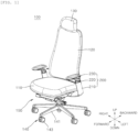
- FIG. 1 is a perspective view showing an armrest assembly and a chair including the same according to one embodiment of the present disclosure.
- a chair 100 includes a seat part 110 which is horizontally disposed at a predetermined height from the ground and on which a user sits, a backrest part 120 disposed to be substantially perpendicular to a rear end portion of the seat part 110 and having an upper end portion disposed to tilt in a front-rear direction with respect to any tilting point of a lower end portion to support the user's back portion, a headrest part 130 disposed in the middle of an upper end portion of the backrest part 120 to support the user's back head portion, and a leg part 140 supporting the seat part 110 at a predetermined height from the ground.
- the chair 100 may further include a manipulation part 150 disposed on a lower surface of the seat part 110 and provided to be connected to respective connecting portions of the seat part 110 and the backrest part 120 to manipulate the seat part 110 to slide in the front-rear direction and the backrest part 120 to tilt and move in the front-rear direction.
- a manipulation part 150 disposed on a lower surface of the seat part 110 and provided to be connected to respective connecting portions of the seat part 110 and the backrest part 120 to manipulate the seat part 110 to slide in the front-rear direction and the backrest part 120 to tilt and move in the front-rear direction.
- the chair 100 may further include an armrest assembly 200 for supporting both arms of a user seated on the seat part 110 at both left and right end portions of the seat part 110.
- an armrest assembly 200 for supporting both arms of a user seated on the seat part 110 at both left and right end portions of the seat part 110. Detailed description of the armrest assembly 200 will be described below.
- the seat part 110 may be provided to slide in the front-rear direction with respect to a seat frame (not shown) so that a seating position may be adjusted according to the user's convenience.
- the seat part 110 may extend in the front-rear direction.
- the seat part 110 may be a part on which the user sits.
- the seat part 110 may support the user's buttocks and a thigh of each of the user's two legs.
- a rear portion that is a portion that supports the user's buttocks may be formed to be slightly recessed downward, and a front portion that is a portion that supports the two thighs of the user may be formed to be inclined to be close to a lower side as it goes forward.
- the backrest part 120 may extend vertically and may extend to be inclined at a predetermined angle so that a lower end portion is positioned in front of an upper end portion.
- the lower end portion of the backrest part 120 may be hinge-coupled to a seat frame (not shown). Therefore, the upper end portion of the backrest part 120 may be adjusted to tilt around a hinge portion of the lower end portion in the front-rear direction.
- the headrest part 130 may extend vertically and may be coupled to the center of the upper end portion of the backrest part 120.
- the headrest part 130 may be formed integrally with the backrest part 120 and may have a lower end portion coupled so that a horizontal shaft formed to extend laterally on a front surface of the upper end portion of the backrest part 120 becomes a rotation center and an upper end portion coupled to tilt in the front-rear direction.
- the leg part 140 may be disposed under the seat part 110 and provided to support the manipulation part 150.
- the leg part 140 may include a plurality of branch frames 141 disposed radially and a moving wheel 143 rotatably coupled to a lower portion of a front end of each of the branch frames 141.
- the branch frames 141 may be formed so that five branch frames are branched at the same angle from the center, but it is sufficient that three or more are formed within the limit that supports the user's seating.
- a cylinder device that is not shown but is installed to be recessed under the seat part 110 may be provided at the center of the branch frame 141, and a height of the seat part 110 may be adjusted by the user's manipulation of the manipulation part 150.
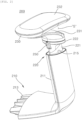
- FIG. 2 is a perspective view showing the armrest assembly according to one embodiment of the present disclosure
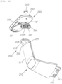
- FIG. 3 is a perspective view showing various rotation states of an armrest pad among components of FIG. 2
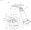
- FIGS. 4A and 4B are downward and upward exploded perspective views of FIG. 2
- FIG. 5 is a side cross-sectional view of a portion of the armrest assembly according to one embodiment of the present disclosure and a partial enlarged view thereof
- FIG. 6 is an exploded perspective view showing another embodiment of a frictional ring of the armrest assembly according to one embodiment of the present disclosure
- FIGS. 7A and 7B are a cut perspective view of a portion of the armrest assembly according to one embodiment of the present disclosure and a partial enlarged view thereof.
- the armrest assembly 200 includes an arm frame body 210 coupled to one side and the other side of a lower portion of both left and right end portions of the seat part 110 and extending upward to a predetermined height, an inner body 220 disposed by being inserted into the arm frame body 210 and disposed to be moved vertically by the user's manipulation, and an arm support pad 230 which is connected to an upper portion of the inner body 220 and on which the user's arms are rested and supported.
- the armrest assembly 200 configured as described above may be provided so that an insertion end 213 formed at a lower end portion of the arm frame body 210 is substantially parallel to the lower surface of the seat part 110 and firmly connected by an assembly screw (not shown) assembled through a fastening member through hole 215 formed to vertically pass through the insertion end 213 after inserted into a coupling end (not shown) of the lower portion of both left and right end portions of the seat part 110.
- the arm frame body 210 may have a portion, which extends to an upper portion excluding a portion parallel to the lower surface of the seat part 110, formed with an inner space in which the inner body 220 may be installed.
- a height adjustment button 250 is provided to be exposed externally on an upper end portion of the inner body 220 installed by being inserted into the inner space of the arm frame body 210, and a rotation lock part (not shown) linked to the height adjustment button 250 is provided inside the inner body 220 so that the user may adjust the arm support pad 230 to a desired height.
- the inner body 220 may include a height adjustment case 221 inserted into the inner space of the arm frame body 210 to adjust the height, and a connection part 222 provided at an upper end of the height adjustment case 221 and mediating the relative rotation connection of the arm support pad 230.
- the arm support pad 230 may be provided to rotate in the left-right direction in a state in which the height is fixed around upper and lower rotation axes of the connection part 222 provided at an upper end of the inner body 220.
- the arm support pad 230 may include a connection pad 231 provided to rotate with respect to the connection part 222 of the inner body 220 and extending forward to be inclined upward, and a support pad 232 integrally connected to an upper side of a front end portion of the connection pad 231 and formed to extend to be parallel backward or inclined upward at a predetermined angle to substantially support the user's arms.
- a safety space S may be formed between respective rear end portions of the connection pad 231 and the support pad 232 to prevent the user's arm from being caught and injured when the tilting of the backrest part 120 is adjusted in the front-rear direction.
- the arm support pad 230 among the components of the armrest assembly 200 according to one embodiment of the present disclosure configured as described above may be provided to rotate around a hinge screw (see reference numeral "240" of FIGS. 4A and 4B ) mediating coupling to the connection part 222 of the inner body 220 in the left-right direction.
- the user's arm may be rested in a state in which the arm support pad 230 is fixed to the center with respect to the hinge screw 240 according to the user's preference as shown in FIG. 3A , and the user's arm may be rested in a state in which a front end portion of the arm support pad 230 is rotated to the left or right at a predetermined angle with respect to the hinge screw 240 according to the user's preference as shown in FIGS. 3B or 3C .
- the arm support pad 230 may be rotatably connected to an upper surface of the connection part 222 of the inner body 220.
- a screw installation hole 235 provided at a portion where the connection pad 231 is formed and provided to install the hinge screw 240 to be described below may be further formed in the safety space S of the arm support pad 230.
- the screw installation hole 235 may be shielded by a hole cover 237 after the hinge screw 240 to be described below is installed.
- An outer surface of the hole cover 237 may be formed in a shape that matches an outer surface forming the safety space S side of the connection pad 231.
- the arm support pad 230 may be rotatably connected to the upper surface of the connection part 222 among the components of the inner body 220 via the hinge screw 240.
- a screw fastening boss in which a screw fastening hole 223h is formed may be provided on an upper surface 223 of the connection part 222 of the inner body 220, and a screw through boss 234 in which a screw through hole 233h is formed at a position corresponding to the screw fastening hole 223h may be provided on a lower surface of the connection pad 231 of the arm support pad 230.
- the arm support pad 230 may be rotatably connected to the connection part 222 of the inner body 220 by allowing the hinge screw 240 to pass through the screw through hole 233h through the screw installation hole 235 of the safety space S side in a state in which the hole cover 237 has been removed and then to be fastened to the screw fastening hole 223h.
- a flat washer 241 may be interposed in the hinge screw 240 as shown in FIG. 5 .
- the flat washer 241 may be supported by a head portion of the hinge screw 240 passing therethrough and at the same time, provided so that an edge end portion supports a peripheral portion of the screw through hole 233h of a bottom surface of the screw installation hole 235 to function to transmit the user's assembly force transmitted to the hinge screw 240 to the arm support pad 230 and support the arm support pad 230 when rotating.
- the flat washer 241 may function to mediate the transmission of the assembly force transmitted from the user to a ring-shaped compression boss 236 formed integrally with a lower end portion of the connection pad 231 to compress a frictional ring 225 to be described below.
- the armrest assembly 200 may further include the frictional ring 225 disposed between the inner body 220 and the arm support pad 230 and providing a frictional force between the inner body 220 and the arm support pad 230 when the arm support pad 230 rotates with respect to the inner body 220.
- the frictional ring 225 may be an elastic body made of a rubber material. Therefore, the frictional ring 225 may be elastically deformed when the assembly force of the hinge screw 240 is transmitted by the ring-shaped compression boss 236 to be described below.
- the frictional force by the frictional ring 225 may be determined by the assembly force of the hinge screw 240 connecting the inner body 220 to the arm support pad 230.
- the frictional ring 225 may be disposed between the inner body 220 and the arm support pad 230 and elastically compressed by the assembly force transmitted through the hinge screw 240 to generate a frictional force on the respective contact surfaces between the two components (the inner body 220 and the arm support pad 230), thereby preventing the arm support pad 230 from rotating arbitrarily when a predetermined assembly force or more is not transmitted.
- a circular installation groove 224 may be formed in the upper surface of the connection part 222, and the frictional ring 225 may be seated in the circular installation groove 224.
- the circular installation groove 224 may be formed in a form in which a non-continuous arc-shaped rib protrudes upward.
- the ring-shaped compression boss 236 may be formed on the lower surface of the connection pad 231 of the arm support pad 230 so as to be formed to have a larger diameter than the screw through boss 234.
- the ring-shaped compression boss 236 functions to uniformly compress an upper surface of the frictional ring 225 when the hinge screw 240 is fastened to the screw fastening hole 223h.
- the uniform compression force of the ring-shaped compression boss 236 on the frictional ring 225 is an operating force adjusted by the user through the hinge screw 240, and at least the frictional ring 225 needs to be formed of an elastic body capable of elastic deformation at a predetermined hardness in order to provide a frictional force corresponding to the above operating force to the ring-shaped compression boss 236.
- a plurality of locking protrusions 225a protruding downward from the lower surface of the frictional ring 225 may be formed on the frictional ring 225. Since the plurality of locking protrusions 225a of the frictional ring 225 formed in this way are respectively fixedly inserted into a plurality of locking grooves 224a formed in the circular installation groove 224 to generate a general uniform frictional force without rotating in conjunction with the ring-shaped compression boss 236, it is possible to solve the problem that the operating force is different for each product.
- the frictional ring 225 may also be applied to the relative rotation structure between the connection pad 231 and the support pad 232, and it goes without saying that a modified embodiment according to the structure of the plurality of locking protrusions 225a and the plurality of locking grooves 224a may also be applied to the frictional ring 225 in this case.
- a plurality of grooves 238 may be repeatedly formed in an outer circumferential surface of the ring-shaped compression boss 236 in a circumferential direction as shown in FIG. 4B , and an operation sense provision part 226 elastically supported toward the plurality of grooves 238 to provide the sense of operation when the arm support pad 230 rotates may be further provided on the upper surface of the connection part 222 of the inner body 220 as shown in FIG. 4A .
- the operation sense provision part 226 may include a member case 227 having an installation space (no reference numeral) that is open toward the plurality of grooves 238 in the upper surface of the connection part 222 of the inner body 220, an elastic rubber 228 provided inside the installation space in the member case 227, and an operation pin 229 having an inner end supported by the elastic rubber 228 and a portion of an outer surface supported to be engaged with the plurality of grooves 238.
- the sense of operation generated as the operation pin 229 elastically supported by the elastic rubber 228 sequentially passes over the plurality of grooves 238 is conversely transmitted to the user so that the user may receive a predetermined sense of operation (sense of manipulation).
- the front end portion of the arm support pad 230 rotates to one side or the other side using the hinge screw 240 as the hinge center.
- the frictional ring 225 provided between the connection part 222 of the arm support pad 230 and the inner body 220 may rotate while forming different frictional forces according to the assembly force according to the preadjustment of the hinge screw 240.
- the rotational force (frictional force) of the arm support pad 230 that is suitable for each user may be adjusted by removing the hole cover 237 and then adjusting the assembly force of the hinge screw 240 using a simple tool.
- the frictional ring 225 may be designed to be uniformly supported by being compressed by the ring-shaped compression boss 236 and can prevent the direct contact assembly of the hinge screw 240 with the arm support pad 230 via the flat washer 241, thereby preventing random loose of the hinge screw 240.
- the armrest assembly 200 and the chair 100 including the same it is possible to minimize manipulation noise by generating the uniform frictional force through the frictional ring 225 between the arm support pad 230 and the inner body 220 when the arm support pad 230 rotates and to simply adjust the rotational force (frictional force) desired by the user for each user.
- the present disclosure provides an armrest assembly and a chair including the same, which are capable of customizing a rotational force (manipulation force) of an arm support pad for each user by adjusting the fastening strength of a hinge screw and prevent random loose of the hinge screw through the even distribution design of the frictional force through a frictional ring.
Landscapes
- Health & Medical Sciences (AREA)
- Dentistry (AREA)
- General Health & Medical Sciences (AREA)
- Seats For Vehicles (AREA)
- Chair Legs, Seat Parts, And Backrests (AREA)
- Special Chairs (AREA)
- Chairs Characterized By Structure (AREA)
Applications Claiming Priority (2)
| Application Number | Priority Date | Filing Date | Title |
|---|---|---|---|
| KR1020220050551A KR102779705B1 (ko) | 2022-04-25 | 2022-04-25 | 암레스트 조립체 및 이를 포함하는 의자 |
| PCT/KR2023/005337 WO2023211051A1 (ko) | 2022-04-25 | 2023-04-20 | 암레스트 조립체 및 이를 포함하는 의자 |
Publications (2)
| Publication Number | Publication Date |
|---|---|
| EP4516163A1 true EP4516163A1 (de) | 2025-03-05 |
| EP4516163A4 EP4516163A4 (de) | 2026-04-01 |
Family
ID=88519373
Family Applications (1)
| Application Number | Title | Priority Date | Filing Date |
|---|---|---|---|
| EP23796698.1A Pending EP4516163A4 (de) | 2022-04-25 | 2023-04-20 | Armlehnenanordnung und stuhl damit |
Country Status (8)
| Country | Link |
|---|---|
| US (1) | US20250031856A1 (de) |
| EP (1) | EP4516163A4 (de) |
| JP (1) | JP2025513421A (de) |
| KR (1) | KR102779705B1 (de) |
| CN (1) | CN119255733A (de) |
| AU (1) | AU2023258871A1 (de) |
| CA (1) | CA3256199A1 (de) |
| WO (1) | WO2023211051A1 (de) |
Family Cites Families (11)
| Publication number | Priority date | Publication date | Assignee | Title |
|---|---|---|---|---|
| US6702386B2 (en) * | 2001-06-15 | 2004-03-09 | Hon Technology Inc. | Height and pivot-adjustable chair arm |
| JP4133287B2 (ja) * | 2002-12-13 | 2008-08-13 | 株式会社内田洋行 | 肘掛け |
| US7234779B2 (en) * | 2005-04-08 | 2007-06-26 | Steelcase Development Corporation | Armrest with height adjustment mechanism |
| JP6045017B2 (ja) * | 2012-05-02 | 2016-12-14 | 株式会社岡村製作所 | 椅子の肘掛け装置 |
| KR101484653B1 (ko) | 2014-04-14 | 2015-01-23 | 주식회사 대하정공 | 의자용 팔걸이 |
| JP7023073B2 (ja) * | 2017-09-01 | 2022-02-21 | 株式会社イトーキ | 肘掛け装置 |
| CN208403806U (zh) * | 2018-02-12 | 2019-01-22 | 开平瑞信家具配件有限公司 | 一种可水平调节的座椅扶手 |
| KR102016648B1 (ko) * | 2018-05-25 | 2019-08-30 | 주식회사 듀오백 | 의자의 암레스트 다단계 회전 및 높낮이 조절 장치 |
| KR20210015185A (ko) * | 2019-08-01 | 2021-02-10 | 조현옥 | 성능을 개선한 인체 공학 사무용 의자 |
| CN116157042A (zh) * | 2020-07-22 | 2023-05-23 | 佛姆维家具有限公司 | 用于椅子的臂组件 |
| CN112167874B (zh) * | 2020-11-06 | 2023-07-07 | 安维车件(厦门)有限公司 | 一种扶手结构和座椅 |
-
2022
- 2022-04-25 KR KR1020220050551A patent/KR102779705B1/ko active Active
-
2023
- 2023-04-20 EP EP23796698.1A patent/EP4516163A4/de active Pending
- 2023-04-20 CA CA3256199A patent/CA3256199A1/en active Pending
- 2023-04-20 CN CN202380034771.XA patent/CN119255733A/zh active Pending
- 2023-04-20 AU AU2023258871A patent/AU2023258871A1/en active Pending
- 2023-04-20 WO PCT/KR2023/005337 patent/WO2023211051A1/ko not_active Ceased
- 2023-04-20 JP JP2024562000A patent/JP2025513421A/ja active Pending
-
2024
- 2024-10-16 US US18/917,461 patent/US20250031856A1/en active Pending
Also Published As
| Publication number | Publication date |
|---|---|
| KR102779705B1 (ko) | 2025-03-12 |
| EP4516163A4 (de) | 2026-04-01 |
| US20250031856A1 (en) | 2025-01-30 |
| AU2023258871A1 (en) | 2024-10-24 |
| WO2023211051A1 (ko) | 2023-11-02 |
| KR20230151191A (ko) | 2023-11-01 |
| JP2025513421A (ja) | 2025-04-24 |
| CN119255733A (zh) | 2025-01-03 |
| CA3256199A1 (en) | 2025-07-03 |
Similar Documents
| Publication | Publication Date | Title |
|---|---|---|
| US5318345A (en) | Tilt back chair and control | |
| KR102206733B1 (ko) | 입체적 위치조절이 가능한 의자용 요추지지장치 | |
| KR101593116B1 (ko) | 의자 등받이 틸팅장치 | |
| US20260041244A1 (en) | Lumbar support assembly and chair including same | |
| US11160377B2 (en) | Synchronous chair mechanism and chair having same | |
| JP2025133119A (ja) | 椅子 | |
| EP4516163A1 (de) | Armlehnenanordnung und stuhl damit | |
| KR101670655B1 (ko) | 의자용 등받이 | |
| KR102668185B1 (ko) | 의자용 팔걸이 및 그가 적용된 의자 | |
| RU2850527C2 (ru) | Подлокотник кресла в сборе и кресло, содержащее такой подлокотник | |
| KR102468097B1 (ko) | 의자 | |
| JP2011092475A (ja) | ロッキング椅子 | |
| KR102115033B1 (ko) | 팔걸이부가 착탈 가능하게 연결되는 의자 | |
| KR101559889B1 (ko) | 높이조절장치 및 그를 구비한 의자 | |
| CN212815352U (zh) | 靠背椅调节结构 | |
| JP2011115570A (ja) | ロッキング椅子 | |
| JP6141634B2 (ja) | 椅子 | |
| CN219460699U (zh) | 一种灵活调整的扶手 | |
| CN223787356U (zh) | 座椅连接结构及座椅 | |
| KR102640132B1 (ko) | 등받이의 틸팅장치 및 그가 적용된 의자 | |
| KR200425075Y1 (ko) | 자동고정되는 의자용 바퀴 | |
| KR102320665B1 (ko) | 요추 지지 성능 개선 의자 | |
| KR102849550B1 (ko) | 셀프 틸팅에 의한 싱크로나이즈 텐션구조의 등받이 일체형 의자본체 | |
| JP6777281B2 (ja) | 椅子 | |
| RU2850523C2 (ru) | Кресло |
Legal Events
| Date | Code | Title | Description |
|---|---|---|---|
| STAA | Information on the status of an ep patent application or granted ep patent |
Free format text: STATUS: THE INTERNATIONAL PUBLICATION HAS BEEN MADE |
|
| PUAI | Public reference made under article 153(3) epc to a published international application that has entered the european phase |
Free format text: ORIGINAL CODE: 0009012 |
|
| STAA | Information on the status of an ep patent application or granted ep patent |
Free format text: STATUS: REQUEST FOR EXAMINATION WAS MADE |
|
| 17P | Request for examination filed |
Effective date: 20241118 |
|
| AK | Designated contracting states |
Kind code of ref document: A1 Designated state(s): AL AT BE BG CH CY CZ DE DK EE ES FI FR GB GR HR HU IE IS IT LI LT LU LV MC ME MK MT NL NO PL PT RO RS SE SI SK SM TR |
|
| DAV | Request for validation of the european patent (deleted) | ||
| DAX | Request for extension of the european patent (deleted) |