EP4512967A1 - Plattenstruktur für einen verborgenen wassertank - Google Patents
Plattenstruktur für einen verborgenen wassertank Download PDFInfo
- Publication number
- EP4512967A1 EP4512967A1 EP24196167.1A EP24196167A EP4512967A1 EP 4512967 A1 EP4512967 A1 EP 4512967A1 EP 24196167 A EP24196167 A EP 24196167A EP 4512967 A1 EP4512967 A1 EP 4512967A1
- Authority
- EP
- European Patent Office
- Prior art keywords
- hinge
- panel
- mounting frame
- water tank
- panel body
- Prior art date
- Legal status (The legal status is an assumption and is not a legal conclusion. Google has not performed a legal analysis and makes no representation as to the accuracy of the status listed.)
- Pending
Links
Images



Classifications
-
- E—FIXED CONSTRUCTIONS
- E03—WATER SUPPLY; SEWERAGE
- E03D—WATER-CLOSETS OR URINALS WITH FLUSHING DEVICES; FLUSHING VALVES THEREFOR
- E03D5/00—Special constructions of flushing devices, e.g. closed flushing system
- E03D5/02—Special constructions of flushing devices, e.g. closed flushing system operated mechanically or hydraulically (or pneumatically) also details such as push buttons, levers and pull-card therefor
- E03D5/028—Pusher plates and actuating mechanisms for built-in cisterns
-
- E—FIXED CONSTRUCTIONS
- E05—LOCKS; KEYS; WINDOW OR DOOR FITTINGS; SAFES
- E05D—HINGES OR SUSPENSION DEVICES FOR DOORS, WINDOWS OR WINGS
- E05D3/00—Hinges with pins
- E05D3/02—Hinges with pins with one pin
-
- E—FIXED CONSTRUCTIONS
- E05—LOCKS; KEYS; WINDOW OR DOOR FITTINGS; SAFES
- E05Y—INDEXING SCHEME ASSOCIATED WITH SUBCLASSES E05D AND E05F, RELATING TO CONSTRUCTION ELEMENTS, ELECTRIC CONTROL, POWER SUPPLY, POWER SIGNAL OR TRANSMISSION, USER INTERFACES, MOUNTING OR COUPLING, DETAILS, ACCESSORIES, AUXILIARY OPERATIONS NOT OTHERWISE PROVIDED FOR, APPLICATION THEREOF
- E05Y2900/00—Application of doors, windows, wings or fittings thereof
- E05Y2900/10—Application of doors, windows, wings or fittings thereof for buildings or parts thereof
- E05Y2900/13—Type of wing
- E05Y2900/132—Doors
Definitions
- the present disclosure relates to the technical field of a panel for a hidden water tank and particularly relates to a panel structure for a hidden water tank.
- the existing panels are fixed to the water tanks by means of buckles, screws, or the like.
- the entire panel needs to be detached for maintenance, which is inconvenient.
- the present disclosure aims to overcome the shortcomings in the prior art and provide a panel structure for a hidden water tank.
- the panel body and the panel mounting frame are connected in a hinged manner and fixed at the end portions in a snap-fit connection.
- the panel body is opened and flipped to a certain angle, so that the user may access the water tank in the wall for maintenance.
- the panel body may be closed directly. This is convenient for operation.
- a technical solution of the present disclosure provides a panel structure for a hidden water tank.
- the panel structure includes a panel mounting frame configured to be connected to a water tank body.
- the panel structure also includes a panel body located on an outer side of the panel mounting frame and configured to be flipped to be opened and closed relative to the panel mounting frame.
- One end of the panel body is connected to the panel mounting frame by means of a hinge, and the other end of the panel body is clamped with the panel mounting frame.
- the panel body is connected to the panel mounting frame by means of two hinges, and the two hinges are arranged at an interval in an up-and-down direction.
- an inner side of the panel body is provided with a hinge mounting arm.
- the hinge mounting arm is provided with an assembly shaft.
- One end of the second hinge connected to the hinge mounting arm has a first connecting hole, and the assembly shaft is in clearance fit with the first connecting hole.
- the hinge mounting arm is located at a periphery of the operation mechanism.
- an edge of the panel mounting frame is provided with a hinge mounting hole, and one end of the first hinge connected to the panel mounting frame has a first pivot shaft.
- the first pivot shaft is in clearance fit with the hinge mounting hole.
- the first hinge includes a first hinge plate, which is provided with a weight reducing hole.
- the second hinge includes two second hinge plates provided in parallel, with a connecting plate connected between the two second hinge plates.
- the other end of the panel body is provided with a buckle/a slot
- the panel mounting frame is correspondingly provided with a slot/a buckle. The buckle is clamped with the slot.
- the present disclosure brings the following beneficial effects.
- the panel structure for a hidden water tank includes a panel mounting frame and a panel body.
- the panel mounting frame is configured to connect and fix a water tank body.
- the panel body is connected to an operation mechanism, and the operation mechanism is configured to operate a valve for opening and closing the water tank.
- One end of the panel body is connected to the panel mounting frame by means of a hinge, so that the panel body may be flipped to be opened and closed relative to the panel mounting frame.
- the other end of the panel body is clamped with the panel mounting frame to fix the closed panel body and prevent it from opening automatically.
- the panel body When maintenance is needed, the panel body is opened and flipped to a certain angle, so that the user may access the water tank in the wall for maintenance. After the maintenance is completed, the panel body may be closed directly. This is convenient for operation.
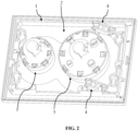
- a panel structure for a hidden water tank comprises a panel mounting frame 1 configured to be connected to a water tank body 8.
- the panel structure for the hidden water tank also comprises a panel body 2 located on an outer side of the panel mounting frame 1 and configured to be flipped for being opened and closed relative to the panel mounting frame 1.
- the "hidden water tank” may be a tank having at least a portion mounted in a wall, a closet, or the like of a bathroom.
- the panel body 2 is connected to an operation mechanism 3.
- One end of the panel body 2 is connected to the panel mounting frame 1 by means of a hinge 4, and the other end of the panel body 2 is clamped with the panel mounting frame 1.
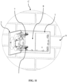
- the panel structure according to the present disclosure is used for a hidden water tank, and the panel structure is configured to be connected to a water tank body 8 mounted in a wall 9.
- the panel structure comprises a panel mounting frame 1 and a panel body 2.
- the panel mounting frame 1 is configured to be connected to and fixed with the water tank body 8.
- the panel mounting frame 1 is connected to the water tank body 8 by means of a number of the connecting members 7, which may be bolts, screws, connecting pipes, or the like.
- the panel body 2 is mounted with an operation mechanism 3, which comprises a button 31.
- a user may press the button 31 to trigger a valve in the water tank body 8 via the operation mechanisms 3.
- two operation mechanisms 3 may be configured, with one operation mechanism 3 configured to trigger the valve to become fully opened, and the other operation mechanism 3 configured to trigger the valve to become half opened.
- the panel body 2 may be flipped to be opened and closed relative to the panel mounting frame 1. Specifically, one end of the panel body 2 is connected to the panel mounting frame 1 by means of the hinges 4, and the other end of the panel body 2 is clamped with the panel mounting frame 1.
- the one end or the other end of the panel body 2 is not limited to an edge of the panel body 2.
- the one end or the other end of the panel body 2 may also refer to a portion of the panel mounting frame 1 or a portion of the panel body 2 that is slightly close to the edge.
- the one end or the other end of the panel body 2 may also refer to one half or the other half of the panel body 2.
- One end of the panel body 2 is connected to one end of the panel mounting frame 1 by means of the hinges 4, which may cause the panel body 2 to be flipped to be opened and closed relative to the panel mounting frame 1.
- the other end of the panel body 2 is clamped with the other end of the panel mounting frame 1 through a snap-fit structure to hold the closed panel body 2 in place, so as to prevent the panel body 2 from being opened automatically.
- the snap-fit structure may adopt a buckle, a clamp plate, a slot, or the like.
- the user When the maintenance is needed, the user merely needs to slightly pull the clamped end of the panel body 2.
- the panel body 2 is flipped to be opened to a preset angle (e.g., 90° - 110°) and then is stopped. At this point, the user may access the parts in the water tank for the maintenance.
- the user rotates the panel body 2 in an opposite direction.
- the panel body 2 is closed and clamped with the panel mounting frame 1.
- the panel body 2 is mounted on the panel mounting frame 1 like a door. This facilitates the operations of opening and closing. There is no need to detach the panel mounting frame 1 and the panel body 2 for the maintenance. This facilitates the maintenance.
- a hinge refers to an element whose two ends are capable of rotating or swinging.
- the hinge adopts a structure, such as a connecting plate and a connecting arm.
- the hinging involved in the present disclosure refers to a connection structure whose two components may rotate or swing relative to each other.
- the two components may be connected by means of a pivot shaft to realize the rotating or swinging relative to each other.
- the panel body 2 is connected to the panel mounting frame 1 by means of two hinges 4.
- the two hinges 4 are arranged at an interval (e.g., spaced apart from each other) in an up-and-down direction. This improves the connection stability between the panel body 2 and the panel mounting frame 1.
- each hinge 4 comprises a first hinge 41 and a second hinge 42 hinged with each other.
- One end of each first hinge 41 is hinged with the panel mounting frame 1, and one end of each second hinge 42 is hinged with the panel body 2.
- each hinge 4 comprises a first hinge 41 and a second hinge 42, which may cause the panel body 2 to be opened at a larger angle.
- the panel body 2 may also be moved toward the outer side of the wall 9 to increase the space for the maintenance and may facilitate the maintenance for the user.
- each first hinge 41 is hinged with the panel mounting frame 1, and the other end of each first hinge 41 is hinged with one end of its corresponding second hinge 42, and one end of each second hinge 42 away from its corresponding first hinge 41 is hinged with the panel body 2.
- each first hinge 41 connected to the panel mounting frame 1 is rotated to be opened at a certain angle
- the panel body 2 is pulled toward the outer side of the wall 9.
- the second hinges 42 and the first hinges 41 may be opened around the points at which the second hinges 42 and the first hinges 41 are hinged.
- the panel body 2 moves outwardly by a certain distance. This increases the space available for the user to operate and facilitates the maintenance.
- the panel body 2 When the panel body 2 is closed, the panel body 2 merely needs to be rotated in an opposite direction.
- the second hinges 42 and the first hinges 41 may be automatically folded. After the clamped end of the panel body 2 contacts the panel mounting frame 1, it may be clamped by being pressed.
- each second hinge 42 connected to its corresponding hinge mounting arm 21 has first connecting holes 422, and each assembly shaft 22 is in clearance fit with (e.g., engaged with or received in) its corresponding first connecting hole 422.
- an inner side of the panel body 2 is provided with the hinge mounting arms 21 configured to mount the second hinges 42, so that each second hinge 42 is spaced apart from the panel body 2 by a certain distance without interference.
- each second hinge 42 is provided with first connecting holes 422, and the other end of each second hinge 42 is provided with second connecting holes 423.
- the assembly shafts 22 pass through their corresponding first connecting holes 422, and the assembly shafts 22 and their corresponding first connecting holes 422 are in clearance fit (e.g., engaged with each other).
- the second connecting holes 423 are in clearance fit with (e.g., engaged with) their corresponding second pivot shafts 413 on one end of each first hinge 41.
- the hinge mounting arm 21 is located at the periphery of its corresponding operation mechanism 3.
- its fulcrum is located in the vicinity of its corresponding operation mechanism 3, so that the operation mechanism 3 is in a position where sufficient space is available. Thus, no interference will occur among the adjacent components.
- the operation mechanism 3 configured to trigger the valve to become fully opened is long, and the hinge mounting arm 21 are desirably arranged in the vicinity of the operation mechanism 3 configured to trigger the valve to become fully opened.
- an edge of the panel mounting frame 1 is provided with the hinge mounting holes 12.
- One end of each first hinge 41 connected to the panel mounting frame 1 has a first pivot shaft 412.
- the first pivot shafts 412 are in clearance fit with (e.g., engaged with or received in) their corresponding hinge mounting holes 12.
- each first hinge 41 is provided with one first pivot shaft 412, and the other end of each first hinge 41 is provided with one second pivot shaft 413.
- the upper and lower ends of each first pivot shaft 412 and each second pivot shaft 413 protrude out of (e.g., extend from) the upper and lower sides of the corresponding first hinge 41, respectively.
- Recesses 11 are provided at an edge of the panel mounting frame 1. Each of the upper and lower recess walls of each recess 11 is provided with a hinge mounting holes 12. One end of each first hinge 41 having the first pivot shaft 412 is in clearance fit with (e.g., engaged with or received in) its corresponding recess 11. Each first pivot shaft 412 is inserted into its corresponding hinge mounting hole 12, and the first pivot shaft 412 and the hinge mounting hole 12 are in clearance fit (e.g., engaged with each other).
- each first hinge 41 comprises a first hinge plate 411, which is provided with a weight reducing hole 414 for reducing the weight.
- each second hinge 42 comprises two second hinge plates 421 provided in parallel, and a connecting plate 424 is connected between the two second hinge plates 421.
- each second hinge 42 comprises two second hinge plates 421 and a connecting plate 424.
- the two second hinge plates 421 are arranged in parallel, and the connecting plate 424 is connected therebetween.
- the connecting plate 424 is shorter than the second hinge plates 421, so that a recess is formed at each end of the two second hinge plates 421 and configured to respectively accommodate one end, having the second pivot shaft 413, of the first hinge 41 and one end, having the assembly shaft 22, of the hinge mounting arm 21.
- each of the two second hinge plates 421 is provided with a first connecting hole 422, and the other end of each of the two second hinge plates 421 is provided with a second connecting hole 423.
- the two ends of the assembly shaft 22 are in clearance fit with (e.g., engaged with or received in) the first connecting holes 422 of the two second hinge plates 421, respectively.
- the two ends of the second pivot shaft 413 are in clearance fit with (e.g., engaged with or received in) the second connecting holes 423 of the two second hinge plates 421, respectively.
- each connecting plate 424 comprises a first connecting plate 4241 and a second connecting plate 4242 arranged in a crosswise manner.
- the first connecting plate 4241 and the second connecting plate 4242 are connected to the two second hinge plates 421, respectively.
- each connecting plate 424 comprises a first connecting plate 4241 and a second connecting plate 4242.
- the two are arranged in a crosswise manner to reinforce the two second hinge plates 421 from different directions. This is beneficial for improving the structure stability of the second hinges 42.
- first connecting plate 4241 and the second connecting plate 4242 are arranged perpendicularly to each other.
- the first connecting plate 4241 extends along the length direction of the second hinge plates 421, and the second connecting plate 4242 extends along the height direction of the second hinge plates 421.
- the other end of the panel body 2 is provided with a buckle 5 or a slot 6.
- the panel mounting frame 1 is correspondingly provided with a slot 6 or a buckle 5, and the buckle 5 is clamped with the slot 6.
- the other end of the panel body 2 and the other end of the panel mounting frame 1 are clamped by means of the slot 6 and the buckle 5.
- the buckle 5 and the slot 6 are configured in two ways as below.
- a buckle 5 is provided at the end of the panel body 2, and a slot 6 is provided at the end of the panel mounting frame 1.
- a slot 6 is provided at the end of the panel body 2, and a buckle 5 is provided at the end of the panel mounting frame 1.
- the user When the panel body 2 is opened, the user only needs to pull outwardly the end of the panel body 2 having the buckle 5 or the slot 6 to detach the buckle 5 from the slot 6, so as to flip the panel body 2.
- the user After the panel body 2 is closed, the user only needs to press the end of the panel body 2 having the buckle 5 or the slot 6 toward the side of the wall 9. Then, a snap sound is heard, indicating that the buckle 5 is clamped in place with the slot 6.
- a toilet may include a base (e.g., a pedestal, a bowl, etc.) and a tank (e.g., the hidden water tank).
- the base is configured to be attached to another object such as a drainpipe, floor, or another suitable object.
- the base includes a bowl, a sump (e.g., a receptacle) disposed below the bowl, and a trapway fluidly connecting the bowl to a drainpipe or sewage line.
- the tank may be supported by the base, such as an upper surface of a rim.
- the tank may be integrally formed with the base as a single unitary body.
- the tank may be formed separately from the base and coupled (e.g., attached, secured, fastened, connected, etc.) to the base.
- the toilet may further include a tank lid covering an opening and inner cavity in the tank.
- the toilet may include a seat assembly including a seat and a seat cover rotatably coupled to the base.
- the toilet arrangement may further include a hinge assembly.
- the toilet arrangement may be a tankless toilet.
- the toilet arrangement includes a base and a seat assembly coupled to the base.
- the base includes a bowl, a sump disposed below the bowl, and a trapway fluidly connecting the bowl to a drainpipe or sewage line.
- the toilet arrangement includes a waterline that supplies the toilet with water.
- the toilet may further include a seat assembly including a seat and a seat cover rotatably coupled to the base.
- a bidet may be included in a seat or pedestal of a toilet. In other examples, the bidet may be manufactured separately from and attached or coupled to a seat or pedestal of a toilet.
- the bidet includes a housing.
- the housing is configured to receive a flow of water through a housing inlet and dispense the flow of water from a housing outlet.
- the housing inlet and housing outlet may be located on opposite ends of the housing from one another, such that water may flow through the housing from the housing inlet to the housing outlet.
- the housing further includes a chamber. As the housing receives the flow of water, the chamber may fill with water and provide a flow of water between the housing inlet and the housing outlet.
- the chamber may be configured to contain the flow of water and direct the flow of water from the housing inlet to the housing outlet. After the chamber has filled with water, the flow of water may travel along a substantially linear path between the housing inlet and the housing outlet.
- one or more walls within the housing may be included to help direct a flow of water between the housing inlet and the housing outlet.
- the bidet may further include a housing inlet conduit configured to direct a flow of water to the housing inlet.
- the housing inlet conduit may be coupled to a water supply such as tank or waterline.
- the housing may further include a gear assembly or a portion of the gear assembly.
- the bidet may be a front wash bidet for female users and may use, generate, and/perform the functions related to nanobubbles, ozonated water, eWater, hydrogen peroxide generation, pH Control, template assisted crystallization, application of polyphosphates, filtration (ultrafiltration, nanofiltration, microfiltration, carbon/GAC), fluidic oscillating sprays, and adding other consumables in the water stream.
- nanobubbles air, ozone, oxygen, hydrogen, and carbon dioxide may be used.
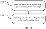
- FIG. 12 is a flow chart of a method for manufacturing a panel structure according to an embodiment of the present disclosure.
- the panel structure in the method may be the panel structure according to any of the embodiments, and the descriptions regarding the panel structure are incorporated herein.
- the panel structure is configured to perform an operation, function, or the like as described in the present disclosure.
- the first end of the panel body 2 is connected to the panel mounting frame 1 via the hinge 4.
- the first hinge 41 of the hinge 4 is connected to the panel mounting frame 1.
- the first pivot shaft 412 of the first hinge 41 is inserted into the hinge mounting hole 12 of the panel mounting frame 1.
- first hinge 41 connected to the panel mounting frame 1 has a first pivot shaft 412.
- the first pivot shafts 412 are in clearance fit with (e.g., engaged with or received in) their corresponding hinge mounting holes 12.
- each first hinge 41 is provided with one first pivot shaft 412, and the other end of each first hinge 41 is provided with one second pivot shaft 413.
- the upper and lower ends of each first pivot shaft 412 and each second pivot shaft 413 protrude out of (e.g., extend from) the upper and lower sides of the corresponding first hinge 41, respectively.
- Recesses 11 are provided at an edge of the panel mounting frame 1. Each of the upper and lower recess walls of each recess 11 is provided with a hinge mounting holes 12. One end of each first hinge 41 having the first pivot shaft 412 is in clearance fit with (e.g., engaged with or received in) its corresponding recess 11. Each first pivot shaft 412 is inserted into its corresponding hinge mounting hole 12, and the first pivot shaft 412 and the hinge mounting hole 12 are in clearance fit (e.g., engaged with each other).
- the second hinge 42 of the hinge 4 is connected to the panel body 2.
- the assembly shaft 22 disposed on the hinge mounting arm 21 of the panel body 2 is inserted into the first connecting hole 422 of the second hinge 42.
- each second hinge 42 connected to its corresponding hinge mounting arm 21 has first connecting holes 422, and each assembly shaft 22 is in clearance fit with (e.g., engaged with or received in) its corresponding first connecting hole 422.
- an inner side of the panel body 2 is provided with the hinge mounting arms 21 configured to mount the second hinges 42, so that each second hinge 42 is spaced apart from the panel body 2 by a certain distance without interference.
- first hinge 41 is connected to the second hinge 42.
- the second pivot shaft 413 of the first hinge 41 is inserted into the second connecting hole 423 of the second hinge 42.
- the second connecting holes 423 are in clearance fit with (e.g., engaged with) their corresponding second pivot shafts 413 on one end of each first hinge 41.
- each first hinge 41 is provided with one first pivot shaft 412, and the other end of each first hinge 41 is provided with one second pivot shaft 413.
- the upper and lower ends of each first pivot shaft 412 and each second pivot shaft 413 protrude out of (e.g., extend from) the upper and lower sides of the corresponding first hinge 41, respectively.
- the buckle 5 and the slot 6 are configured in two ways as below.
- a buckle 5 is provided at the end of the panel body 2, and a slot 6 is provided at the end of the panel mounting frame 1.
- a slot 6 is provided at the end of the panel body 2, and a buckle 5 is provided at the end of the panel mounting frame 1.
- the user When the panel body 2 is opened, the user only needs to pull outwardly the end of the panel body 2 having the buckle 5 or the slot 6 to detach the buckle 5 from the slot 6, so as to flip the panel body 2.
- the user After the panel body 2 is closed, the user only needs to press the end of the panel body 2 having the buckle 5 or the slot 6 toward the side of the wall 9. Then, a snap sound is heard, indicating that the buckle 5 is clamped in place with the slot 6.
- An aspect provides a panel structure for a hidden water tank, comprising a panel mounting frame for being connected with a water tank body and a panel body located on an outer side of the panel mounting frame and capable of being flipped to be opened and closed relative to the panel mounting frame;
- the panel body may be connected with the panel mounting frame by means of two hinges.
- the two hinges may be arranged at an interval in an up-and-down direction.
- the hinge may comprise a first hinge and a second hinge hinged with each other, one end of the first hinge being hinged with the panel mounting frame, and one end of the second hinge being hinged with the panel body.
- an inner side of the panel body is provided with a hinge mounting arm
- the hinge mounting arm is provided with an assembly shaft
- one end of the second hinge connected with the hinge mounting arm has a first connecting hole
- the assembly shaft is in clearance fit with the first connecting hole
- the hinge mounting arm may be located at a periphery of the operation mechanism.
- an edge of the panel mounting frame is provided with a hinge mounting hole, and one end of the first hinge connected with the panel mounting frame has a first pivot shaft; and the first pivot shaft is in clearance fit with the hinge mounting hole.
- the first hinge may comprise a first hinge plate.
- the first hinge plate may be provided with a weight reducing hole.
- the second hinge may comprise two second hinge plates provided in parallel.
- a connecting plate may be connected between the two second hinge plates.
- the connecting plate may comprise a first connecting plate and a second connecting plate arranged in a crosswise manner, the first connecting plate and the second connecting plate being connected with the two second hinge plates, respectively.
- the other end of the panel body may be provided with a buckle/a slot
- the panel mounting frame may be correspondingly provided with a slot/a buckle
- the buckle may be clamped with the slot.
Landscapes
- Engineering & Computer Science (AREA)
- Mechanical Engineering (AREA)
- Aviation & Aerospace Engineering (AREA)
- Health & Medical Sciences (AREA)
- Life Sciences & Earth Sciences (AREA)
- Hydrology & Water Resources (AREA)
- Public Health (AREA)
- Water Supply & Treatment (AREA)
- Hinges (AREA)
Applications Claiming Priority (1)
| Application Number | Priority Date | Filing Date | Title |
|---|---|---|---|
| CN202322307012.6U CN220908576U (zh) | 2023-08-25 | 2023-08-25 | 一种用于隐藏式水箱的面板结构 |
Publications (1)
| Publication Number | Publication Date |
|---|---|
| EP4512967A1 true EP4512967A1 (de) | 2025-02-26 |
Family
ID=90920774
Family Applications (1)
| Application Number | Title | Priority Date | Filing Date |
|---|---|---|---|
| EP24196167.1A Pending EP4512967A1 (de) | 2023-08-25 | 2024-08-23 | Plattenstruktur für einen verborgenen wassertank |
Country Status (3)
| Country | Link |
|---|---|
| US (1) | US20250067097A1 (de) |
| EP (1) | EP4512967A1 (de) |
| CN (1) | CN220908576U (de) |
Families Citing this family (1)
| Publication number | Priority date | Publication date | Assignee | Title |
|---|---|---|---|---|
| CA3198697A1 (en) * | 2022-05-04 | 2023-11-04 | Console Vault Llc | Secure door hinge assembly for security compartment |
Citations (3)
| Publication number | Priority date | Publication date | Assignee | Title |
|---|---|---|---|---|
| KR20110010882U (ko) * | 2010-05-17 | 2011-11-23 | 유병하 | 조립식 물탱크용 맨홀 |
| EP2128350B1 (de) * | 2008-05-29 | 2021-08-04 | GROHEDAL Sanitärsysteme GmbH | Spülkasten mit Revisionsöffnung |
| EP3587681B1 (de) * | 2018-06-26 | 2021-12-15 | Geberit International AG | Lagerplatte für spülkästen |
Family Cites Families (5)
| Publication number | Priority date | Publication date | Assignee | Title |
|---|---|---|---|---|
| US1424550A (en) * | 1920-06-21 | 1922-08-01 | William H Aschburner | Balancing cover support |
| US2903149A (en) * | 1958-01-30 | 1959-09-08 | Counter Balance Inc | Counterbalanced cover lift |
| US3093258A (en) * | 1960-06-09 | 1963-06-11 | Oswald W Turner | Cover lift |
| IT1304909B1 (it) * | 1998-10-13 | 2001-04-05 | Tgn S P A | Cerniera a scatto per il sostegno di elementi piastriformi dichiusura. |
| DE20207036U1 (de) * | 2002-05-03 | 2003-09-18 | Mepla-Werke Lautenschläger GmbH & Co. KG, 64354 Reinheim | Kreuzgelenkscharnier |
-
2023
- 2023-08-25 CN CN202322307012.6U patent/CN220908576U/zh active Active
-
2024
- 2024-08-22 US US18/812,444 patent/US20250067097A1/en active Pending
- 2024-08-23 EP EP24196167.1A patent/EP4512967A1/de active Pending
Patent Citations (3)
| Publication number | Priority date | Publication date | Assignee | Title |
|---|---|---|---|---|
| EP2128350B1 (de) * | 2008-05-29 | 2021-08-04 | GROHEDAL Sanitärsysteme GmbH | Spülkasten mit Revisionsöffnung |
| KR20110010882U (ko) * | 2010-05-17 | 2011-11-23 | 유병하 | 조립식 물탱크용 맨홀 |
| EP3587681B1 (de) * | 2018-06-26 | 2021-12-15 | Geberit International AG | Lagerplatte für spülkästen |
Also Published As
| Publication number | Publication date |
|---|---|
| CN220908576U (zh) | 2024-05-07 |
| US20250067097A1 (en) | 2025-02-27 |
Similar Documents
| Publication | Publication Date | Title |
|---|---|---|
| US20250067097A1 (en) | Panel structure for a hidden water tank | |
| JP6143062B2 (ja) | トイレ装置 | |
| US12123185B2 (en) | Toilet bidet device and toilet | |
| JP2021055320A (ja) | 水洗大便器 | |
| US20240011271A1 (en) | Toilet cover base, toilet cover assembly, and toilet | |
| RU2449090C2 (ru) | Защитно-маскировочный кожух для унитаза и унитаз с таким кожухом | |
| JP5626870B2 (ja) | 収納一体型便器及びその施工方法 | |
| US20250179850A1 (en) | Panel assembly | |
| US12070166B2 (en) | Toilet seat ring | |
| JP2005120639A (ja) | トイレユニット | |
| EP4520883A1 (de) | Verborgene wassertankvorrichtung | |
| JP2001152530A (ja) | タンクレス便器 | |
| JP4451043B2 (ja) | 配管隠蔽用のカバー構造 | |
| CN215127840U (zh) | 一种具有给皂功能的浴室柜 | |
| JPH10195955A (ja) | 便器ロータンク及び便器システム | |
| CN113774633A (zh) | 一种洗衣机 | |
| JP7467141B2 (ja) | トイレ装置 | |
| CN213606040U (zh) | 一种新型浴室柜 | |
| EP4201281B1 (de) | Toilettensitzring | |
| JP7501240B2 (ja) | 衛生洗浄装置およびトイレ装置 | |
| EP4512970A2 (de) | Spülrohr und toilettenspülsystem | |
| JP5013947B2 (ja) | 便器固定装置 | |
| JP2001090164A (ja) | タンクレス便器 | |
| JP2003230447A (ja) | キャビネット取付構造 | |
| JP2003301503A (ja) | トイレの排水構造 |
Legal Events
| Date | Code | Title | Description |
|---|---|---|---|
| PUAI | Public reference made under article 153(3) epc to a published international application that has entered the european phase |
Free format text: ORIGINAL CODE: 0009012 |
|
| STAA | Information on the status of an ep patent application or granted ep patent |
Free format text: STATUS: THE APPLICATION HAS BEEN PUBLISHED |
|
| AK | Designated contracting states |
Kind code of ref document: A1 Designated state(s): AL AT BE BG CH CY CZ DE DK EE ES FI FR GB GR HR HU IE IS IT LI LT LU LV MC ME MK MT NL NO PL PT RO RS SE SI SK SM TR |
|
| STAA | Information on the status of an ep patent application or granted ep patent |
Free format text: STATUS: REQUEST FOR EXAMINATION WAS MADE |
|
| 17P | Request for examination filed |
Effective date: 20250728 |