EP4512657A1 - Heizverfahren und -vorrichtung für traktionsbatterie und elektronische vorrichtung, system und speichermedium - Google Patents
Heizverfahren und -vorrichtung für traktionsbatterie und elektronische vorrichtung, system und speichermedium Download PDFInfo
- Publication number
- EP4512657A1 EP4512657A1 EP23794864.1A EP23794864A EP4512657A1 EP 4512657 A1 EP4512657 A1 EP 4512657A1 EP 23794864 A EP23794864 A EP 23794864A EP 4512657 A1 EP4512657 A1 EP 4512657A1
- Authority
- EP
- European Patent Office
- Prior art keywords
- heating
- power battery
- self
- preset
- current state
- Prior art date
- Legal status (The legal status is an assumption and is not a legal conclusion. Google has not performed a legal analysis and makes no representation as to the accuracy of the status listed.)
- Pending
Links
Images


Classifications
-
- B—PERFORMING OPERATIONS; TRANSPORTING
- B60—VEHICLES IN GENERAL
- B60L—PROPULSION OF ELECTRICALLY-PROPELLED VEHICLES; SUPPLYING ELECTRIC POWER FOR AUXILIARY EQUIPMENT OF ELECTRICALLY-PROPELLED VEHICLES; ELECTRODYNAMIC BRAKE SYSTEMS FOR VEHICLES IN GENERAL; MAGNETIC SUSPENSION OR LEVITATION FOR VEHICLES; MONITORING OPERATING VARIABLES OF ELECTRICALLY-PROPELLED VEHICLES; ELECTRIC SAFETY DEVICES FOR ELECTRICALLY-PROPELLED VEHICLES
- B60L58/00—Methods or circuit arrangements for monitoring or controlling batteries or fuel cells, specially adapted for electric vehicles
- B60L58/10—Methods or circuit arrangements for monitoring or controlling batteries or fuel cells, specially adapted for electric vehicles for monitoring or controlling batteries
- B60L58/24—Methods or circuit arrangements for monitoring or controlling batteries or fuel cells, specially adapted for electric vehicles for monitoring or controlling batteries for controlling the temperature of batteries
- B60L58/27—Methods or circuit arrangements for monitoring or controlling batteries or fuel cells, specially adapted for electric vehicles for monitoring or controlling batteries for controlling the temperature of batteries by heating
-
- B—PERFORMING OPERATIONS; TRANSPORTING
- B60—VEHICLES IN GENERAL
- B60L—PROPULSION OF ELECTRICALLY-PROPELLED VEHICLES; SUPPLYING ELECTRIC POWER FOR AUXILIARY EQUIPMENT OF ELECTRICALLY-PROPELLED VEHICLES; ELECTRODYNAMIC BRAKE SYSTEMS FOR VEHICLES IN GENERAL; MAGNETIC SUSPENSION OR LEVITATION FOR VEHICLES; MONITORING OPERATING VARIABLES OF ELECTRICALLY-PROPELLED VEHICLES; ELECTRIC SAFETY DEVICES FOR ELECTRICALLY-PROPELLED VEHICLES
- B60L3/00—Electric devices on electrically-propelled vehicles for safety purposes; Monitoring operating variables, e.g. speed, deceleration or energy consumption
- B60L3/0023—Detecting, eliminating, remedying or compensating for drive train abnormalities, e.g. failures within the drive train
- B60L3/0061—Detecting, eliminating, remedying or compensating for drive train abnormalities, e.g. failures within the drive train relating to electrical machines
-
- B—PERFORMING OPERATIONS; TRANSPORTING
- B60—VEHICLES IN GENERAL
- B60L—PROPULSION OF ELECTRICALLY-PROPELLED VEHICLES; SUPPLYING ELECTRIC POWER FOR AUXILIARY EQUIPMENT OF ELECTRICALLY-PROPELLED VEHICLES; ELECTRODYNAMIC BRAKE SYSTEMS FOR VEHICLES IN GENERAL; MAGNETIC SUSPENSION OR LEVITATION FOR VEHICLES; MONITORING OPERATING VARIABLES OF ELECTRICALLY-PROPELLED VEHICLES; ELECTRIC SAFETY DEVICES FOR ELECTRICALLY-PROPELLED VEHICLES
- B60L3/00—Electric devices on electrically-propelled vehicles for safety purposes; Monitoring operating variables, e.g. speed, deceleration or energy consumption
- B60L3/12—Recording operating variables ; Monitoring of operating variables
-
- B—PERFORMING OPERATIONS; TRANSPORTING
- B60—VEHICLES IN GENERAL
- B60L—PROPULSION OF ELECTRICALLY-PROPELLED VEHICLES; SUPPLYING ELECTRIC POWER FOR AUXILIARY EQUIPMENT OF ELECTRICALLY-PROPELLED VEHICLES; ELECTRODYNAMIC BRAKE SYSTEMS FOR VEHICLES IN GENERAL; MAGNETIC SUSPENSION OR LEVITATION FOR VEHICLES; MONITORING OPERATING VARIABLES OF ELECTRICALLY-PROPELLED VEHICLES; ELECTRIC SAFETY DEVICES FOR ELECTRICALLY-PROPELLED VEHICLES
- B60L58/00—Methods or circuit arrangements for monitoring or controlling batteries or fuel cells, specially adapted for electric vehicles
- B60L58/10—Methods or circuit arrangements for monitoring or controlling batteries or fuel cells, specially adapted for electric vehicles for monitoring or controlling batteries
- B60L58/12—Methods or circuit arrangements for monitoring or controlling batteries or fuel cells, specially adapted for electric vehicles for monitoring or controlling batteries responding to state of charge [SoC]
-
- B—PERFORMING OPERATIONS; TRANSPORTING
- B60—VEHICLES IN GENERAL
- B60L—PROPULSION OF ELECTRICALLY-PROPELLED VEHICLES; SUPPLYING ELECTRIC POWER FOR AUXILIARY EQUIPMENT OF ELECTRICALLY-PROPELLED VEHICLES; ELECTRODYNAMIC BRAKE SYSTEMS FOR VEHICLES IN GENERAL; MAGNETIC SUSPENSION OR LEVITATION FOR VEHICLES; MONITORING OPERATING VARIABLES OF ELECTRICALLY-PROPELLED VEHICLES; ELECTRIC SAFETY DEVICES FOR ELECTRICALLY-PROPELLED VEHICLES
- B60L58/00—Methods or circuit arrangements for monitoring or controlling batteries or fuel cells, specially adapted for electric vehicles
- B60L58/10—Methods or circuit arrangements for monitoring or controlling batteries or fuel cells, specially adapted for electric vehicles for monitoring or controlling batteries
- B60L58/24—Methods or circuit arrangements for monitoring or controlling batteries or fuel cells, specially adapted for electric vehicles for monitoring or controlling batteries for controlling the temperature of batteries
- B60L58/26—Methods or circuit arrangements for monitoring or controlling batteries or fuel cells, specially adapted for electric vehicles for monitoring or controlling batteries for controlling the temperature of batteries by cooling
-
- H—ELECTRICITY
- H01—ELECTRIC ELEMENTS
- H01M—PROCESSES OR MEANS, e.g. BATTERIES, FOR THE DIRECT CONVERSION OF CHEMICAL ENERGY INTO ELECTRICAL ENERGY
- H01M10/00—Secondary cells; Manufacture thereof
- H01M10/42—Methods or arrangements for servicing or maintenance of secondary cells or secondary half-cells
- H01M10/44—Methods for charging or discharging
- H01M10/443—Methods for charging or discharging in response to temperature
-
- H—ELECTRICITY
- H01—ELECTRIC ELEMENTS
- H01M—PROCESSES OR MEANS, e.g. BATTERIES, FOR THE DIRECT CONVERSION OF CHEMICAL ENERGY INTO ELECTRICAL ENERGY
- H01M10/00—Secondary cells; Manufacture thereof
- H01M10/60—Heating or cooling; Temperature control
- H01M10/61—Types of temperature control
- H01M10/615—Heating or keeping warm
-
- H—ELECTRICITY
- H01—ELECTRIC ELEMENTS
- H01M—PROCESSES OR MEANS, e.g. BATTERIES, FOR THE DIRECT CONVERSION OF CHEMICAL ENERGY INTO ELECTRICAL ENERGY
- H01M10/00—Secondary cells; Manufacture thereof
- H01M10/60—Heating or cooling; Temperature control
- H01M10/61—Types of temperature control
- H01M10/617—Types of temperature control for achieving uniformity or desired distribution of temperature
-
- H—ELECTRICITY
- H01—ELECTRIC ELEMENTS
- H01M—PROCESSES OR MEANS, e.g. BATTERIES, FOR THE DIRECT CONVERSION OF CHEMICAL ENERGY INTO ELECTRICAL ENERGY
- H01M10/00—Secondary cells; Manufacture thereof
- H01M10/60—Heating or cooling; Temperature control
- H01M10/62—Heating or cooling; Temperature control specially adapted for specific applications
- H01M10/625—Vehicles
-
- H—ELECTRICITY
- H01—ELECTRIC ELEMENTS
- H01M—PROCESSES OR MEANS, e.g. BATTERIES, FOR THE DIRECT CONVERSION OF CHEMICAL ENERGY INTO ELECTRICAL ENERGY
- H01M10/00—Secondary cells; Manufacture thereof
- H01M10/60—Heating or cooling; Temperature control
- H01M10/63—Control systems
- H01M10/633—Control systems characterised by algorithms, flow charts, software details or the like
-
- H—ELECTRICITY
- H01—ELECTRIC ELEMENTS
- H01M—PROCESSES OR MEANS, e.g. BATTERIES, FOR THE DIRECT CONVERSION OF CHEMICAL ENERGY INTO ELECTRICAL ENERGY
- H01M10/00—Secondary cells; Manufacture thereof
- H01M10/60—Heating or cooling; Temperature control
- H01M10/63—Control systems
- H01M10/637—Control systems characterised by the use of reversible temperature-sensitive devices, e.g. NTC, PTC or bimetal devices; characterised by control of the internal current flowing through the cells, e.g. by switching
-
- H—ELECTRICITY
- H01—ELECTRIC ELEMENTS
- H01M—PROCESSES OR MEANS, e.g. BATTERIES, FOR THE DIRECT CONVERSION OF CHEMICAL ENERGY INTO ELECTRICAL ENERGY
- H01M10/00—Secondary cells; Manufacture thereof
- H01M10/60—Heating or cooling; Temperature control
- H01M10/65—Means for temperature control structurally associated with the cells
- H01M10/656—Means for temperature control structurally associated with the cells characterised by the type of heat-exchange fluid
- H01M10/6567—Liquids
- H01M10/6568—Liquids characterised by flow circuits, e.g. loops, located externally to the cells or cell casings
-
- H—ELECTRICITY
- H01—ELECTRIC ELEMENTS
- H01M—PROCESSES OR MEANS, e.g. BATTERIES, FOR THE DIRECT CONVERSION OF CHEMICAL ENERGY INTO ELECTRICAL ENERGY
- H01M10/00—Secondary cells; Manufacture thereof
- H01M10/60—Heating or cooling; Temperature control
- H01M10/65—Means for temperature control structurally associated with the cells
- H01M10/657—Means for temperature control structurally associated with the cells by electric or electromagnetic means
- H01M10/6571—Resistive heaters
-
- H—ELECTRICITY
- H01—ELECTRIC ELEMENTS
- H01M—PROCESSES OR MEANS, e.g. BATTERIES, FOR THE DIRECT CONVERSION OF CHEMICAL ENERGY INTO ELECTRICAL ENERGY
- H01M10/00—Secondary cells; Manufacture thereof
- H01M10/60—Heating or cooling; Temperature control
- H01M10/66—Heat-exchange relationships between the cells and other systems, e.g. central heating systems or fuel cells
-
- B—PERFORMING OPERATIONS; TRANSPORTING
- B60—VEHICLES IN GENERAL
- B60L—PROPULSION OF ELECTRICALLY-PROPELLED VEHICLES; SUPPLYING ELECTRIC POWER FOR AUXILIARY EQUIPMENT OF ELECTRICALLY-PROPELLED VEHICLES; ELECTRODYNAMIC BRAKE SYSTEMS FOR VEHICLES IN GENERAL; MAGNETIC SUSPENSION OR LEVITATION FOR VEHICLES; MONITORING OPERATING VARIABLES OF ELECTRICALLY-PROPELLED VEHICLES; ELECTRIC SAFETY DEVICES FOR ELECTRICALLY-PROPELLED VEHICLES
- B60L2240/00—Control parameters of input or output; Target parameters
- B60L2240/10—Vehicle control parameters
- B60L2240/36—Temperature of vehicle components or parts
-
- B—PERFORMING OPERATIONS; TRANSPORTING
- B60—VEHICLES IN GENERAL
- B60L—PROPULSION OF ELECTRICALLY-PROPELLED VEHICLES; SUPPLYING ELECTRIC POWER FOR AUXILIARY EQUIPMENT OF ELECTRICALLY-PROPELLED VEHICLES; ELECTRODYNAMIC BRAKE SYSTEMS FOR VEHICLES IN GENERAL; MAGNETIC SUSPENSION OR LEVITATION FOR VEHICLES; MONITORING OPERATING VARIABLES OF ELECTRICALLY-PROPELLED VEHICLES; ELECTRIC SAFETY DEVICES FOR ELECTRICALLY-PROPELLED VEHICLES
- B60L2240/00—Control parameters of input or output; Target parameters
- B60L2240/40—Drive Train control parameters
- B60L2240/54—Drive Train control parameters related to batteries
- B60L2240/545—Temperature
-
- H—ELECTRICITY
- H01—ELECTRIC ELEMENTS
- H01M—PROCESSES OR MEANS, e.g. BATTERIES, FOR THE DIRECT CONVERSION OF CHEMICAL ENERGY INTO ELECTRICAL ENERGY
- H01M2220/00—Batteries for particular applications
- H01M2220/20—Batteries in motive systems, e.g. vehicle, ship, plane
-
- Y—GENERAL TAGGING OF NEW TECHNOLOGICAL DEVELOPMENTS; GENERAL TAGGING OF CROSS-SECTIONAL TECHNOLOGIES SPANNING OVER SEVERAL SECTIONS OF THE IPC; TECHNICAL SUBJECTS COVERED BY FORMER USPC CROSS-REFERENCE ART COLLECTIONS [XRACs] AND DIGESTS
- Y02—TECHNOLOGIES OR APPLICATIONS FOR MITIGATION OR ADAPTATION AGAINST CLIMATE CHANGE
- Y02E—REDUCTION OF GREENHOUSE GAS [GHG] EMISSIONS, RELATED TO ENERGY GENERATION, TRANSMISSION OR DISTRIBUTION
- Y02E60/00—Enabling technologies; Technologies with a potential or indirect contribution to GHG emissions mitigation
- Y02E60/10—Energy storage using batteries
Definitions
- the present application relates to the technical field of batteries, and specifically relates to a method for heating a power battery, an apparatus for heating a power battery, an electronic device, a system for heating a power battery, and a storage medium.
- power batteries are widely used in the fields of new energy vehicles, consumer electronics, energy storage systems and the like.
- use of the power batteries in a low-temperature environment will be restricted to a certain extent. Specifically, discharge capacity of the power batteries will severely decline in the low-temperature environment, and the power batteries fail to be charged in the low-temperature environment.
- the present application provides a method for heating a power battery, an apparatus for heating a power battery, an electronic device, a system for heating a power battery, and a storage medium, which can solve the problems in the prior art of severe decline of the discharge capacity of the power battery in a low-temperature environment, and failure to charge the power battery in a low-temperature environment.
- simple summary is provided below. The summary is neither intended to provide extensive review, nor intended to identify key/important elements or depict the scope of protection of these embodiments. Its sole purpose is to present some concepts in simple forms as a prelude to detailed description bellow.
- the present application provides a method for heating a power battery, including:
- the current state parameter value of the power battery is acquired, and the power battery is heated using the corresponding heating mode based on the current state parameter value. After temperature rise, the discharge capacity of the power battery increases, and charging can be achieved, thereby solving the technical problems in the prior art of severe decline of the discharge capacity of the power battery in a low-temperature environment and failure to charge the power battery in a low-temperature environment.
- the heating the power battery using the corresponding heating mode based on the current state parameter value includes: heating the power battery using a self-heating mode and/or an external heating mode based on the current state parameter value.
- the heating mode includes self-heating and/or external heating, which facilitates the selection of an appropriate heating mode based on the current state parameter value, can perform external heating on the power battery when self-heating is not suitable, overcomes the defect in the prior art of a single heating mode of the power battery, and solves the technical problem of failure to satisfy the actual application requirements only by self-heating.
- the current state parameter value comprises a current temperature value and a current state of charge value
- the heating the power battery using the corresponding heating mode based on the current state parameter value includes: heating the power battery using the self-heating mode, in response to the current temperature value of the power battery being smaller than a first preset temperature and a state of charge of the power battery being greater than a preset charge threshold.
- Reasonable arrangement of a preset self-heating condition can ensure that the self-heating mode is selected when the current state parameter value is most suitable for self-heating.
- the heating the power battery using the self-heating mode includes: controlling a charging and discharging circuit where the power battery is located to alternately form a charging loop and a discharging loop, to heat the power battery.
- the charging loop and the discharging loop are alternately formed, and an AC current is used to generate heat to heat the power battery, thus achieving high heating efficiency.
- the method further includes:
- the assisted heating of the power battery using the motor coolant can make full use of the heat of the coolant, avoid energy waste, and improve the heating efficiency and heating effects.
- the performing motor coolant-assisted heating includes: controlling the motor coolant to flow through an external pipeline of the power battery, and performing assisted heating on the power battery using the motor coolant.
- the assisted heating of the power battery using the motor coolant can make full use of the heat of the coolant, avoid energy waste, and improve the heating efficiency and heating effects.
- the method further includes:
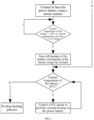
- the current state parameter value comprises the current temperature value of the power battery; and the determining whether the current state parameter value of the power battery satisfies the preset self-heating stop condition includes: determining that the current state parameter value satisfies the preset self-heating stop condition, in response to the current temperature value being larger than a second preset temperature. Since the self-heating efficiency is low when the preset self-heating stop condition is satisfied, self-heating is stopped when the preset self-heating stop condition is satisfied, which can avoid inefficient self-heating, and avoid energy loss generated in the motor windings during self-heating.
- the current state parameter value comprises a current temperature rise rate of the power battery; and the determining whether the current state parameter value of the power battery satisfies the preset self-heating stop condition includes: determining that the current state parameter value satisfies the preset self-heating stop condition, in response to the current temperature rise rate being smaller than a preset rate. The determining whether self-heating should be stopped based on the temperature rise rate can ensure that self-heating is stopped at a low temperature rise rate, thereby avoiding energy loss caused by inefficient self-heating.
- the method further includes: further controlling, in response to determining that the power battery is being heated using a motor coolant when the preset self-heating stop condition is satisfied, to stop heating the power battery using the motor coolant. Stopping the coolant-assisted heating can further avoid energy loss caused by controlling the coolant flow.
- the current state parameter value comprises a current temperature value and a current state of charge value; and the heating the power battery using the corresponding heating mode based on the current state parameter value includes:
- the heating the power battery using the external heating mode includes: controlling an external heat source to heat the power battery.
- the external heat source is controlled to perform external heating on the power battery, thus achieving high heating efficiency.
- the present application provides an apparatus for heating a power battery, including:
- the technical solutions provided in the second aspect can be used for implementing the method provided in the first aspect, can acquire the current state parameter value of the power battery, and heat the power battery using the corresponding heating mode based on the current state parameter value. After temperature rise, the discharge capacity of the power battery increases, and charging can be achieved, thereby solving the technical problems in the prior art of severe decline of the discharge capacity of the power battery in a low-temperature environment and failure to charge the power battery in a low-temperature environment.
- the present application provides an electronic device, comprising a memory, a processor, and a computer program stored on the memory and executable on the processor.
- the processor executes the program to implement the heating method in any one of the above embodiments.
- the technical solutions provided in the third aspect can implement the heating method in the first aspect, thereby achieving the same beneficial technical effects as the first aspect.
- the present application provides a system for heating a power battery, comprising a controller, a charging and discharging circuit connected to the controller, and an external heat source, wherein the controller is configured to implement the heating method in any one of the above embodiments.
- the technical solutions provided in the fourth aspect can implement the heating method in the first aspect, thereby achieving the same beneficial technical effects as the first aspect.
- the charging and discharging circuit comprises a switch module, an energy storage module, and a charge and discharge switching module;
- the switch module and the charge and discharge switching module form the charging and discharging loop under the control of the controller, to charge and discharge the power battery to achieve self-heating of the power battery.
- the external heat source comprises a PTC heating apparatus.
- the PTC heating apparatus is adapted to external heating on the power battery with high heating efficiency.
- the present application provides a computer-readable storage medium storing a computer program thereon.
- the program is executed by a processor to implement the heating method in any one of the above embodiments.
- the technical solutions provided in the fifth aspect can implement the heating method in the first aspect, thereby achieving the same beneficial technical effects as the first aspect.
- the present application provides a battery power plant, comprising a power battery and the heating system in the fourth aspect, wherein the power battery is configured to provide power, and the heating system is configured to heat the power battery.
- the technical solutions provided in the sixth aspect can implement the heating method in the first aspect, thereby achieving the same beneficial technical effects as the first aspect.
- an embodiment means that a particular feature, structure, or characteristic described in connection with the embodiment can be included in at least one embodiment of the present application.
- the appearance of this phrase in various places in the specification does not necessarily refer to the same embodiment, nor is it a separate or alternative embodiment that is mutually exclusive with other embodiments. It is explicitly and implicitly understood by those skilled in the art that the embodiments described herein may be combined with other embodiments.
- a plurality of refers to two or more (including two).
- multiple groups refers to two or more groups (including two groups), and “multiple pieces” refers to two or more pieces (including two pieces).
- the technical terms “mounting”, “connection”, “connection” and “fixation” should be understood in a broad sense, for example, they can be fixed connection, detachable connection, or integration; or they can be mechanical connection or electrical connection; or they can be direct connection, indirect connection through an intermediate medium, or communication of the interiors of two elements or the relationship of interaction between two elements.
- the specific meanings of the above terms in the embodiments of the present application can be understood based on specific situations.
- New energy vehicles powered by power batteries have the advantages of good environmental protection effects, low noise, and low costs, can effectively promote energy conservation and emission reduction, have huge market prospects, and are conducive to sustainable economic development. Due to the electrochemical characteristics of power batteries, the performance of power batteries is greatly limited in a low-temperature environment, thereby seriously affecting user experience in winter driving. Therefore, in order to use a power battery normally, it is necessary to heat the power battery in a low-temperature environment.
- the inventors discovered that when the power battery is in a low-temperature state, the lower the temperature is, the higher the internal resistance of the battery is, and the better the heating effects are. With the temperature rise, the internal resistance of the battery gradually decreases, and the heating effects of the battery decrease, which is manifested as the increasingly smaller temperature rise rate (temperature rise value per minute °C/min) of the battery.
- the electric vehicle can be equipped with a self-heating apparatus for the power battery (such as a lithium-ion battery) to heat the power battery.
- the basic principle of self-heating of the power battery is to discharge current from the power battery and then charge the current back using the increased internal resistance of the power battery at a low temperature. In this way, the current flows through the internal resistance of the power battery, heat is generated inside the power battery, and the temperature rises, thereby achieving the purpose of heating the power battery.
- the defect of the self-heating mode of the power battery is that its effects are limited by a state of charge parameter value and its own temperature: self-heating can be performed only when the power battery has certain state of charge. If the state of charge is too low, self-heating cannot be performed.
- the power battery is greatly limited by its own temperature. After the temperature rise of the power battery, the internal resistance of the power battery becomes smaller, and the self-heating efficiency decreases. Therefore, if the power battery is only equipped with the self-heating mode, the heating mode is too single, and fails to satisfy the actual application requirements.
- Self-heating of the power battery is a kind of self-excitation, which uses a motor drive system to first discharge the battery energy and then charge the energy back.
- the power battery is first required to have certain state of charge (SOC), so that a large current can be excited on positive and negative electrode busbars of the battery for heating; and if the battery has insufficient state of charge, it fails to generate sufficient heating current, thus failing to guarantee the heating effects.
- SOC state of charge
- the power battery and the motor drive system are required for self-heating of the power battery. In this case, the power battery and the motor are in a special working mode, so that charging or driving cannot be performed during self-heating.
- the power battery involved in the embodiments of the present application may be a lithium-ion battery, a lithium metal battery, a lead-acid battery, a nickel-cadmium battery, a nickel-metal hydride battery, a lithium-sulfur battery, a lithium-air battery, or a sodium-ion battery, etc., which is not limited here.
- the power battery in the embodiments of the present application may be a battery cell, or may be a battery module or a battery pack, which is not limited here.
- the power battery may be used in a power plant, such as a vehicle or a ship. For example, it may be used in a power vehicle, to power a motor of the power vehicle, and serve as a power source of the electric vehicle.
- the power battery may also power other electrical devices in the electric vehicle, such as a vehicle air conditioner or a vehicle player.
- a first embodiment of the present application provides a method for heating a power battery.
- the method includes:
- the heating the power battery using the corresponding heating mode based on the current state parameter value includes: heating the power battery using a self-heating mode and/or an external heating mode based on the current state parameter value.
- a preset heating condition satisfied by the current state parameter value is determined, and the power battery is heated using a heating mode corresponding to the satisfied preset heating condition.
- the heating mode includes self-heating and/or external heating.
- the preset heating condition may include, for example, a preset self-heating condition and a preset external heating condition.
- the current state parameter value comprises a current temperature value and a current state of charge value
- the step S20 includes: heating the power battery using the self-heating mode if the current temperature value of the power battery is smaller than a first preset temperature and the state of charge of the power battery is greater than a preset charge threshold.
- the power battery is heated using the self-heating mode.
- Reasonable arrangement of the preset self-heating condition can ensure that a most appropriate heating mode is selected when a heating mode is selected based on the current state parameter value.
- the first preset temperature may specifically be set based on actual requirements, for example, may be set to 0°C, 3°C, or 5°C, etc.
- the preset charge threshold may specifically be set based on actual requirements, for example, may be set to 20%, 25%, or 30%, etc.
- the heating the power battery using the self-heating mode includes: controlling a charging and discharging circuit where the power battery is located to alternately form a charging loop and a discharging loop, to heat the power battery.
- the charging loop and the discharging loop are alternately formed, and an AC current is used to generate heat to heat the power battery, thus achieving high efficiency.
- the method for heating a power battery in an embodiment of the present application acquires the current state parameter value of the power battery, and heats the power battery using the corresponding heating mode based on the current state parameter value. After temperature rise, the discharge capacity of the power battery increases, and charging can be achieved, thereby solving the technical problems in the prior art of severe decline of the discharge capacity of the power battery in a low-temperature environment and failure to charge the power battery in a low-temperature environment.
- the method further includes:
- the preset temperature difference may specifically be set based on actual requirements, for example, may be set to 5°C, 6°C, or 8°C, etc.
- the performing motor coolant-assisted heating includes: controlling the motor coolant to flow through an external pipeline of the power battery, and performing assisted heating on the power battery using the motor coolant.
- the assisted heating of the power battery using the motor coolant can make full use of the heat of the coolant, avoid energy waste, and improve the heating efficiency and heating effects.
- the step S20 includes: determining whether the current state parameter value satisfies the preset self-heating condition or the preset external heating condition; and controlling the charging and discharging circuit to charge and discharge the power battery to achieve self-heating, in response to the current state parameter value satisfying the preset self-heating condition. Whether the preset self-heating condition or the preset external heating condition is satisfied is determined based on the current state parameter value, to select the corresponding heating mode based on the determination result, which can ensure that a most appropriate heating mode is selected, and can ensure that self-heating is performed when self-heating is most suitable.
- said step may further include: controlling an external heat source to perform external heating on the power battery, in response to the preset external heating condition being satisfied. Whether the preset self-heating condition or the preset external heating condition is satisfied is determined based on the current state parameter value, to select the corresponding heating mode based on the determination result, which can ensure that a most appropriate heating mode is selected, and can ensure that external heating of the power battery is performed when external heating is most suitable.
- the current state parameter value may be compared with the preset self-heating condition and the preset external heating condition to determine whether the current state parameter value satisfies the preset self-heating condition or satisfies the preset external heating condition.
- the current state parameter value comprises a current temperature value and a current state of charge value
- the preset self-heating condition includes the current temperature of the power battery being within a first preset interval and the state of charge of the power battery being within a second preset interval
- the preset external heating condition includes the current temperature of the power battery being within a third preset interval or the state of charge of the power battery being within a fourth preset interval.
- a right end of the first preset interval is the aforementioned first preset temperature, and a left end of the first preset interval may be - ⁇ .
- a left end of the second preset interval is the aforementioned preset charge threshold, and a right end of the second preset interval is 100%.
- a left end of the third preset interval is the aforementioned first preset temperature, and a right end of the third preset interval is the aforementioned third preset temperature.
- a left end of the fourth preset interval is 0, and a right end of the fourth preset interval is the aforementioned preset charge threshold.
- An intersection of the first preset interval and the third preset interval is an empty set, and an intersection of the second preset interval and the fourth preset interval is an empty set.
- An opening/closing state on a right side of the first preset interval can be set based on actual application requirements.
- An opening/closing state of the second preset interval can be set based on actual application requirements.
- An opening/closing state of the third preset interval can be set based on actual application requirements.
- An opening/closing state of the fourth preset interval can be set based on actual application requirements.
- the power battery When the state of charge of the power battery is within the second preset interval, the power battery can be ensured to have sufficient state of charge for discharging and charging.
- the current temperature of the power battery When the current temperature of the power battery is within the first preset interval, due to the low temperature in the first preset interval, the power battery has large internal resistance and high self-heating efficiency, which can achieve quick temperature rise of the power battery. In this case, the self-heating mode has highest heating efficiency and best heating effects.
- the external heating mode can be used to make up for the defect of the decrease of the self-heating efficiency. For example, heating by the external heat source, such as a PTC heater, can achieve high heating efficiency.
- the external heating mode can be used to improve the heating efficiency, and enable the power battery to quickly reach a high temperature.
- heating by the external heat source such as the PTC heater, can achieve high heating efficiency.
- the settings may be as follows: the first preset interval is (- ⁇ , 0), the second preset interval is [20%, 100%], the third preset interval is [0, 20), and the fourth preset interval is [0, 20%). That is, the preset self-heating condition includes the current temperature of the power battery being lower than 0°C and the state of charge of the power battery being greater than or equal to 20%, and the preset external heating condition includes: the current temperature of the power battery being higher than or equal to 0°C and lower than 20°C, or the state of charge of the power battery being greater than or equal to 0 and less than 20%.
- the settings may also be as follows: the first preset interval is (- ⁇ , 5), the second preset interval is [30%, 100%], the third preset interval is [5, 18), and the fourth preset interval is [0, 30%).
- the settings may also be as follows: the first preset interval is (- ⁇ , 3), the second preset interval is [25%, 100%], the third preset interval is [3, 22), and the fourth preset interval is [0, 25%).
- Other intervals may also be set based on actual application requirements.
- the heating method provided in the embodiment of the present application determines the preset heating condition satisfied by the current state parameter value of the power battery, and heats the power battery using the heating mode corresponding to the satisfied preset heating condition.
- the heating mode includes self-heating and external heating, thereby selecting an appropriate heating mode, performing external heating on the power battery when self-heating is not suitable, overcoming the defect in the prior art of a single heating mode of the power battery, and solving the technical problem of failure to satisfy the actual application requirements only by self-heating.
- the method further includes:
- the charging and discharging process of the power battery is stopped, thereby stopping self-heating. Since the self-heating efficiency is low when the preset self-heating stop condition is satisfied, self-heating is stopped when the preset self-heating stop condition is satisfied, which can avoid inefficient self-heating, and avoid energy loss generated in the motor windings during self-heating.
- the current state parameter value comprises the current temperature value of the power battery; and the determining whether the current state parameter value of the power battery satisfies the preset self-heating stop condition includes: determining that the current state parameter value satisfies the preset self-heating stop condition, in response to the current temperature value being larger than a second preset temperature. Since the self-heating efficiency is low when the preset self-heating stop condition is satisfied, self-heating is stopped when the preset self-heating stop condition is satisfied, which can avoid inefficient self-heating, and avoid energy loss generated in the motor windings during self-heating.
- the second preset temperature may be set based on actual requirements, for example, may be set to 10°C, 11°C, or 12°C, etc.
- the second preset temperature is higher than the first preset temperature.
- the preset rate may be set based on actual requirements, for example, may be set to 0.2°C/min, 0.3°C/min, or 0.4°C/min.
- the method further includes: S50: further controlling, in response to determining that the power battery is being heated using a motor coolant when the preset self-heating stop condition is satisfied, to stop heating the power battery using the motor coolant.
- Stopping the coolant-assisted heating can further avoid energy loss caused by controlling the coolant flow.
- the current state parameter value comprises a current temperature value and a current state of charge value
- the third preset temperature may be set based on actual requirements, for example, may be set to 18°C, 20°C, or 22°C, etc.
- the third preset temperature is higher than the second preset temperature.
- the heating the power battery using the external heating mode includes: controlling an external heat source to heat the power battery.
- Whether the preset self-heating condition or the preset external heating condition is satisfied is determined based on the current state parameter value, to select the corresponding heating mode based on the determination result, which can ensure that a most appropriate heating mode is selected, and can ensure that external heating of the power battery is performed when external heating is most suitable.
- the current state parameter value of the power battery satisfies the preset self-heating stop condition during self-heating is determined.
- the current state parameter value of the power battery is acquired in real time, and whether the current state parameter value satisfies the preset self-heating stop condition is determined.
- the preset self-heating stop condition may include, for example, at least one of two conditions: the current temperature of the power battery is within a seventh preset interval and the current temperature rise rate of the power battery is within an eighth preset interval.
- the current state parameter value of the power battery comprises the current temperature of the power battery; and the preset self-heating stop condition includes the current temperature of the power battery being within the seventh preset interval.
- Reasonable arrangement of the preset self-heating stop condition can ensure that self-heating is stopped in a most appropriate situation, thereby avoiding energy loss caused by inefficient self-heating.
- a left end of the seventh preset interval is the aforementioned second preset temperature.
- a right end of the seventh preset interval may be + ⁇ .
- An opening/closing state on a left side of the seventh preset interval may be set based on actual requirements, for example, may be set to (10, + ⁇ ), [11, + ⁇ ), or (12, + ⁇ ), etc.
- the current state parameter value of the power battery comprises the current temperature rise rate of the power battery; and the preset self-heating stop condition includes the current temperature rise rate of the power battery being within the eighth preset interval.
- the method before the determining whether the current state parameter value of the power battery satisfies the preset self-heating stop condition, the method further includes: acquiring the temperature rise rate of the power battery in real time when the charging and discharging circuit is controlled to charge and discharge the power battery to achieve self-heating.
- the determining whether self-heating should be stopped based on the temperature rise rate can ensure that self-heating is stopped at a low temperature rise rate, thereby avoiding energy loss caused by inefficient self-heating. Since the preset self-heating stop condition used in this example involves the temperature rise rate of the power battery, it is necessary to acquire the temperature rise rate of the power battery in real time when the charging and discharging circuit is controlled to charge and discharge the power battery to achieve self-heating, to determine whether the current temperature rise rate of the power battery satisfies the preset self-heating stop condition.
- the temperature rise rate may be computed by a battery management system (BMS). To acquire the temperature rise rate of the power battery, the temperature rise rate may be read directly from the battery management system (BMS).
- BMS battery management system
- a right endpoint of the eighth preset interval is the aforementioned preset rate.
- An opening/closing state of the seventh preset interval may be set based on actual requirements, for example, may be set to [0, 0.2), [0, 0.3], or [0, 0.4), etc.
- the unit of the temperature rise rate is °C/min. Taking the eighth preset interval being [0, 0.2) as an example, when the temperature rise rate is smaller than 0.2°C/min, the preset self-heating stop condition is reached.
- the charging and discharging circuit is controlled to stop charging and discharging the power battery, to stop self-heating.
- the controlling to stop charging and discharging the power battery can be implemented by controlling the disconnection of the charging and discharging loop.
- step S40 is skipped to, that is, maintaining self-heating, acquiring the current state parameter value of the power battery in real time, and determining whether the preset self-heating stop condition is satisfied.
- a right end of the sixth preset interval is the aforementioned third preset temperature.
- a left end of the sixth preset interval may be - ⁇ .
- An opening/closing state on a right side of the sixth preset interval may be set based on actual requirements, for example, may be set to (- ⁇ , 20), (- ⁇ , 21], or (- ⁇ , 22), etc.
- the external heat source is controlled to perform external heating on the power battery. After self-heating is stopped, external heating is started, so that external heating can be performed in a state most suitable for external heating, to most efficiently enhance the temperature of the power battery.
- the electric vehicle When the power battery is heated by the external heat source, such as the PTC heating apparatus, the electric vehicle is allowed to travel or the power battery is allowed to be charged.
- the external heat source such as the PTC heating apparatus
- the temperature of the power battery is acquired in real time.
- the temperature of the power battery exceeds the sixth preset interval, external heating of the power battery is stopped.
- the sixth preset interval being (- ⁇ , 20) as an example, if the current temperature of the power battery reaches 20°C or above, the external heat source is controlled to stop heating the power battery.
- the temperature of the power battery exceeds the sixth preset interval, the temperature of the power battery can satisfy the actual application requirements, so that it is not necessary to further continue heating. Therefore, heating of the power battery is stopped.
- the motor During self-heating of the power battery, the motor generates heat due to the current flowing through the windings.
- An effluent temperature of the motor coolant (the coolant is usually water, but of course, may also be other liquids for cooling the motor) may be detected.
- the outputted coolant may be introduced into an external liquid flow channel of the power battery, for assisted heating of the power battery.
- a second embodiment of the present application provides a method for heating a power battery.
- the method further includes:
- the power battery is controlled to be heated using the motor coolant.
- the assisted heating of the power battery using the motor coolant can make full use of the heat of the coolant, avoid energy waste, and improve the heating efficiency and heating effects.
- the motor windings will generate heat due to the current flowing therethrough.
- a coolant in a motor cooling system absorbs the heat emitted from the motor windings and its temperature rises.
- An effluent temperature of the motor cooling system can be detected.
- the coolant can be introduced into an external liquid flow channel of the power battery to heat the power battery, thereby making full use of the heat of the coolant, avoiding energy waste, and improving the heating efficiency and heating effects.
- the method further includes:
- the method in this embodiment further includes the steps S60 to S80 in the last embodiment. That is, the method in this embodiment includes: sequentially executed steps S10 to S30, steps S40' to S80', as well as determining whether the current temperature of the power battery is within the sixth preset interval, controlling the external heat source to perform external heating on the power battery in response to the current temperature of the power battery being within the sixth preset interval, determining in real time whether the temperature of the power battery exceeds the sixth preset interval, and stopping external heating of the power battery in response to the temperature of the power battery exceeding the sixth preset interval.
- a method for heating a power battery including the following steps:
- a controller controls a coolant to circulate between a liquid flow channel of a motor drive system and an external liquid flow channel of the battery, thereby achieving assisted heating of the power battery using the heat of the coolant.
- a controller controls the PTC heater to input its own water into an external liquid flow channel of the power battery, and then the water flows back to the PTC heater from the external liquid flow channel of the power battery, thereby performing external heating on the power battery through circulation flow.
- the internal resistance of the battery will gradually decrease, so that the self-heating effects of the battery will gradually become worse.
- the electric drive system is still excited for self-heating, so that the energy consumption will still be very large, but the heating effects of the battery are poor.
- self-heating of the battery is switched off to avoid high energy consumption under self-heating, and the external heating mode is switched to for heating the power battery, that is, the PTC heater is switched on for heating.
- the battery After the PTC heater is switched on for heating, the battery has spent an inefficient heating interval of the PTC heater due to rapid temperature rise of self-heating (the lower the temperature is, the worse the PTC heating effects are). Heating by the PTC heater from the current temperature achieves high heating efficiency and small energy consumption, and is energy-saving. In addition, switching on the PTC heater for heating does not affect the vehicle charging or driving, and is time-saving.
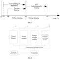
- a third embodiment of the present application provides a system for heating a power battery, comprising a controller, a charging and discharging circuit connected to the controller, and an external heat source.
- the controller can be configured to implement the method for heating a power battery in any one of the above embodiments.
- the charging and discharging circuit comprises a switch module 2, an energy storage module 3, and a charge and discharge switching module 4; the switch module 2, the charge and discharge switching module 4, and a power battery 1 are connected in parallel; a first terminal of the energy storage module 3 is connected to the switch module, and a second terminal of the energy storage module 3 is connected to the charge and discharge switching module 4; the switch module 2 and the charge and discharge switching module 4 are configured to form a charging and discharging loop under the control of the controller, to charge and discharge the power battery 1 to achieve self-heating; and the external heat source is configured to perform external heating on the power battery 1 under the control of the controller.
- the switch module and the charge and discharge switching module form the charging and discharging loop under the control of the controller, to charge and discharge the power battery to achieve self-heating of the power battery.
- the energy storage module 3 may comprise a motor winding
- the switch module 2 may comprise a motor inverter
- the external heat source comprises a PTC heating apparatus.
- An external heating apparatus in other forms may also serve as the external heat source.
- the PTC heating apparatus is adapted to external heating on the power battery with high heating efficiency.
- the PTC heating apparatus is, for example, a PTC heater.
- the PTC heater can hydrothermally heat the power battery, that is, PTC resistance wire generates heat to heat the coolant, and then the heated coolant is introduced into an external liquid flow channel of the power battery.
- the power battery absorbs heat in the external liquid flow channel, and is gradually heated up.
- the heating method using the PTC heater is adapted to many working conditions, and is also adapted even during charging or driving.
- the charge and discharge switching module comprises a first switching circuit and a second switching circuit connected in series; a connection point of the first switching circuit and the second switching circuit is connected to the second terminal of the energy storage module; and the first switching circuit and the second switching circuit are configured to be switched on or off when triggered by a charge/discharge enable signal.
- an energy storage module 3 comprises three-phase windings of the motor.
- the three-phase windings are winding 311, winding 312, and winding 313 respectively.
- a switch module 2 comprises a bridge arm 21, a bridge arm 22, and a bridge arm 23 of a motor inverter. Internal resistance of a power battery 1 is R.
- a charge and discharge switching module 4 comprises a first switching circuit and a second switching circuit connected in series.
- the first switching circuit comprises a first upper bridge arm
- the second switching circuit comprises a first lower bridge arm; and a connection point of the first upper bridge arm and the first lower bridge arm is connected to a neutral point of the three-phase windings.
- the first upper bridge arm comprises a first switch and a first diode connected in parallel
- the first lower bridge arm comprises a second switch and a second diode connected in parallel
- a negative electrode of the first diode is connected to a positive electrode of a power supply module
- a positive electrode of the first diode is connected to a negative electrode of the second diode
- a positive electrode of the second diode is connected to a negative electrode of a first battery pack.
- the upper bridge arm 41 is the first upper bridge arm
- the lower bridge arm 42 is the first lower bridge arm.
- the upper bridge arm 41 comprises a first switch V7 and a first diode D7 connected in parallel
- the lower bridge arm 42 comprises a second switch V8 and a second diode D8 connected in parallel
- a negative electrode of the first diode D7 is connected to a positive electrode of the power battery
- a positive electrode of the first diode D7 is connected to a negative electrode of the second diode D8
- a positive electrode of the second diode D8 is connected to a negative electrode of the power battery.
- the first upper bridge arm may only comprise the first switch, but does not comprise the first diode
- the first lower bridge arm may only comprise the second switch, but does not comprise the second diode.
- connection point of the upper bridge arm 211 and the lower bridge arm 212 of the bridge arm 21 is connected to one terminal of the winding 311, and a connection point of the upper bridge arm 221 and the lower bridge arm 222 of the bridge arm 22 is connected to one terminal of the winding 312.
- a connection point of the upper bridge arm 231 and the lower bridge arm 232 of the arm 23 is connected to one terminal of the winding 313, and a connection point of the upper bridge arm 41 and the lower bridge arm 42 of the charge and discharge switching module 4 is connected to the neutral point of the three-phase windings.
- the upper bridge arm 211 comprises a switch V1 and a diode D1 connected in parallel
- the lower bridge arm 212 comprises a switch V4 and a diode D4 connected in parallel
- the upper bridge arm 221 comprises a switch V2 and a diode D2 connected in parallel
- the lower bridge arm 222 comprises a switch V5 and a diode D5 connected in parallel
- the upper bridge arm 231 comprises a switch V3 and a diode D3 connected in parallel
- the lower bridge arm 232 comprises a switch V6 and a diode D6 connected in parallel.
- Negative electrodes of D1, D2, and D3 are all connected to the positive electrode of the power battery 1
- positive electrodes of D4, D5, and D6 are all connected to the negative electrode of the power battery 1.
- the power battery 1, the upper bridge arms 211-231, the windings 311-313, and the lower bridge arm 42 jointly form a discharging loop; and the power battery 1, the lower bridge arms 212-232, the windings 311-313, and the upper bridge arm 41 jointly form a charging loop.
- the charging loop and the discharging loop are periodically switched on alternately.
- this charging and discharging circuit will not cause the three-phase motor to operate, thereby solving the problem of heat generation by the rotor in the motor, and extending the self-heating service time of the power battery.
- the discharging loop and the charging loop can be implemented simply by ensuring that an upper bridge arm of three-phase bridge arms of the windings 311-313 and a lower bridge arm 42 of the charge and discharge switching module 4 connected to the neutral point of the three-phase windings simultaneously keep ON or OFF of switches, and a lower bridge arm of three-phase bridge arms of the windings 311-313 and an upper bridge arm 41 of the charge and discharge switching module 4 connected to the neutral point of the three-phase windings simultaneously keep ON or OFF of the switches.
- the system for heating a power battery provided in this embodiment can be configured to implement the heating method in any one of the above embodiments, and can achieve the same beneficial effects as the heating method.
- a fourth embodiment of the present application provides an apparatus for heating a power battery.
- the heating apparatus comprises:
- the heating module is configured to heat the power battery using a heating mode corresponding to a preset heating condition satisfied by the current state parameter value.
- the heating mode includes self-heating and/or external heating.
- the apparatus for heating a power battery in the present application is configured to implement the heating method in any one of the above embodiments, acquire the current state parameter value of the power battery, and heat the power battery using the corresponding heating mode based on the current state parameter value. After temperature rise, the discharge capacity of the power battery increases, and charging can be achieved, thereby solving the technical problems in the prior art of severe decline of the discharge capacity of the power battery in a low-temperature environment and failure to charge the power battery in a low-temperature environment.
- the current state parameter value comprises a current temperature value and a current state of charge value
- the heating module is further specifically configured to: heat the power battery using the self-heating mode, in response to the current temperature value of the power battery being smaller than a first preset temperature and a state of charge of the power battery being greater than a preset charge threshold.
- the heating the power battery using the self-heating mode performed by the heating module includes: controlling a charging and discharging circuit where the power battery is located to alternately form a charging loop and a discharging loop, to heat the power battery.
- the heating apparatus further comprises:
- the performing motor coolant-assisted heating performed by the determination unit includes: controlling the motor coolant to flow through an external pipeline of the power battery, and performing assisted heating on the power battery using the motor coolant.
- the apparatus further comprises:
- the current state parameter value comprises the current temperature value of the power battery; and the preset self-heating stop condition determination module is specifically further configured to: determine that the current state parameter value satisfies the preset self-heating stop condition, in response to the current temperature value being larger than a second preset temperature.
- the current state parameter value comprises a current temperature rise rate of the power battery; and the preset self-heating stop condition determination module is specifically further configured to: determine that the current state parameter value satisfies the preset self-heating stop condition, in response to the current temperature rise rate being smaller than a preset rate.
- the apparatus further comprises: a coolant heating stop module configured to further control, in response to determining that the power battery is being heated using a motor coolant when the preset self-heating stop condition is satisfied, to stop heating the power battery using the motor coolant.
- a coolant heating stop module configured to further control, in response to determining that the power battery is being heated using a motor coolant when the preset self-heating stop condition is satisfied, to stop heating the power battery using the motor coolant.
- the current state parameter value comprises a current temperature value and a current state of charge value; and the heating module is further specifically configured to:
- the heating the power battery using the external heating mode performed by the heating module includes: controlling an external heat source to heat the power battery.
- the heating apparatus determines the preset heating condition satisfied by the current state parameter value of the power battery, and heats the power battery using the heating mode corresponding to the satisfied preset heating condition.
- the heating mode includes self-heating and external heating, thereby selecting an appropriate heating mode, performing external heating on the power battery when self-heating is not suitable, overcoming the defect in the prior art of a single heating mode of the power battery, and solving the technical problem of failure to satisfy actual application requirements only by self-heating.
- a fifth embodiment of the present application provides an electronic device, comprising a memory, a processor, and a computer program stored on the memory and executable on the processor.
- the processor executes the computer program to implement the heating method in any one of the above embodiments.
- the electronic device 10 may comprise: a processor 100, a memory 101, a bus 102, and a communication interface 103.
- the processor 100, the communication interface 103, and the memory 101 are connected through the bus 102; the memory 101 stores a computer program executable on the processor 100, and the processor 100 executes, when running the computer program, the method provided in any one of the above embodiments of the present application.
- the memory 101 may include a high-speed random access memory (RAM), and may further include a non-volatile memory, e.g., at least one disk memory.
- RAM random access memory
- a communication connection between the system network element and at least one other network element may be implemented through at least one communication interface 103 (either wired or wireless) using the Internet, a wide area network, a local network, a metropolitan area network, or the like.
- the bus 102 may be an ISA bus, a PCI bus, an EISA bus, or the like.
- the bus may be classified into an address bus, a data bus, or a control bus, etc.
- the memory 101 is configured to store a program, the processor 100 executes the program after receiving an execution instruction, and the method disclosed in any one embodiment among the above embodiments of the present application may be applied to the processor 100 or implemented by the processor 100.
- the processor 100 may be an integrated circuit chip with a signal processing capability. In an implementation process, steps of the above method may be completed by an integrated logic circuit of hardware in the processor 100 or instructions in the form of software.
- the above processor 100 may be a general-purpose processor, including a Central Processing Unit (abbreviated as CPU), and a network processor (abbreviated as NP), etc., or may be a digital signal processor (DSP), an application specific integrated circuit (ASIC), a field programmable gate array (FPGA) or other programmable logic devices, a discrete gate or transistor logic device, or a discrete hardware component, and can implement or execute the methods, steps, and logical block diagrams disclosed in the embodiments of the present application.
- CPU Central Processing Unit
- NP network processor
- DSP digital signal processor
- ASIC application specific integrated circuit
- FPGA field programmable gate array
- the general-purpose processor may be a microprocessor or the processor may also be any conventional processor or the like.
- the steps of the method disclosed in the embodiments of the present application may be directly embodied as being executed and completed by a hardware decoding processor, or being executed and completed by a combination of hardware and software modules in the decoding processor.
- the software module may be located in a mature storage medium in the art, such as a random access memory, a flash memory, a read-only memory, a programmable read-only memory or an electrically erasable programmable memory, or a register.
- the storage medium is located in the memory 101.
- the processor 100 reads information from the memory 101, and completes the steps of the above method in combination with its hardware.
- the electronic device provided in the embodiments of the present application is derived from a same inventive concept as the method provided in the embodiments of the present application, and has same beneficial effects as the method adopted, operated, or implemented thereof.
- a sixth embodiment of the present application provides a computer-readable storage medium storing a computer program thereon.
- the program is executed by a processor to implement the heating method in any one of the above embodiments.
- examples of the computer-readable storage medium may further include, but are not limited to, a phase-change random-access memory (PRAM), a static random-access memory (SRAM), a dynamic random-access memory (DRAM), a random-access memory (RAM) of other type, a read-only memory (ROM), an electrically erasable programmable read-only memory (EEPROM), a flash RAM or other optical or magnetic storage mediums, which will not be detailed one by one here.
- PRAM phase-change random-access memory
- SRAM static random-access memory
- DRAM dynamic random-access memory
- RAM random-access memory
- ROM read-only memory
- EEPROM electrically erasable programmable read-only memory
- flash RAM or other optical or magnetic storage mediums
- the computer-readable storage medium provided in the above embodiments of the present application is derived from a same inventive concept as the method provided in the embodiments of the present application, and has same beneficial effects as the method adopted, operated, or implemented in an application program stored therein.
- a seventh embodiment of the present application provides a battery power plant, comprising a power battery and the heating system in any one of the above embodiments, wherein the power battery is configured to provide power, and the heating system is configured to heat the power battery.
- the battery power plant may be, for example, an apparatus powered by a battery, such as an electric vehicle.
- module is not intended to be limited to a particular physical form. Depending on a specific application, the module may be implemented as hardware, firmware, software, and/or a combination thereof. In addition, different modules may share a common component or even be implemented by a same component. There may or may not be clear boundaries between different modules.
- steps in the flow charts of the drawings are shown in a sequence as indicated by the arrows, these steps are not necessarily executed in the sequence indicated by the arrows. Unless explicitly stated herein, the execution of these steps is not strictly limited in sequence, and may also be executed in other sequences. Further, at least some of the steps in the flow charts of the drawings may include a plurality of sub-steps or a plurality of stages. These sub-steps or stages are not necessarily executed at a same moment, but may be executed at different moments, may not necessarily be performed sequentially in an execution sequence, but may be performed in turn or alternately with other steps or sub-steps of other steps or at least some of the stages.
Landscapes
- Engineering & Computer Science (AREA)
- Manufacturing & Machinery (AREA)
- Chemical & Material Sciences (AREA)
- Chemical Kinetics & Catalysis (AREA)
- Electrochemistry (AREA)
- General Chemical & Material Sciences (AREA)
- Power Engineering (AREA)
- Life Sciences & Earth Sciences (AREA)
- Sustainable Development (AREA)
- Sustainable Energy (AREA)
- Transportation (AREA)
- Mechanical Engineering (AREA)
- Automation & Control Theory (AREA)
- Electromagnetism (AREA)
- Physics & Mathematics (AREA)
- Secondary Cells (AREA)
- Charge And Discharge Circuits For Batteries Or The Like (AREA)
Applications Claiming Priority (2)
| Application Number | Priority Date | Filing Date | Title |
|---|---|---|---|
| CN202210434648.4A CN115366743B (zh) | 2022-04-24 | 2022-04-24 | 动力电池的加热方法、装置、电子设备、系统及存储介质 |
| PCT/CN2023/082739 WO2023207429A1 (zh) | 2022-04-24 | 2023-03-21 | 动力电池的加热方法、装置、电子设备、系统及存储介质 |
Publications (2)
| Publication Number | Publication Date |
|---|---|
| EP4512657A1 true EP4512657A1 (de) | 2025-02-26 |
| EP4512657A4 EP4512657A4 (de) | 2025-09-10 |
Family
ID=84060508
Family Applications (1)
| Application Number | Title | Priority Date | Filing Date |
|---|---|---|---|
| EP23794864.1A Pending EP4512657A4 (de) | 2022-04-24 | 2023-03-21 | Heizverfahren und -vorrichtung für traktionsbatterie und elektronische vorrichtung, system und speichermedium |
Country Status (4)
| Country | Link |
|---|---|
| US (1) | US20250055056A1 (de) |
| EP (1) | EP4512657A4 (de) |
| CN (1) | CN115366743B (de) |
| WO (1) | WO2023207429A1 (de) |
Families Citing this family (5)
| Publication number | Priority date | Publication date | Assignee | Title |
|---|---|---|---|---|
| CN115366743B (zh) * | 2022-04-24 | 2024-02-02 | 宁德时代新能源科技股份有限公司 | 动力电池的加热方法、装置、电子设备、系统及存储介质 |
| CN115966812A (zh) * | 2022-12-12 | 2023-04-14 | 浙江极氪智能科技有限公司 | 电池加热系统的控制方法及电池加热系统、电动车辆 |
| CN117728075B (zh) * | 2023-12-19 | 2024-06-28 | 佛山科学技术学院 | 一种低温环境下的锂离子电池自加热方法及其加热装置 |
| CN119840482A (zh) * | 2024-09-30 | 2025-04-18 | 比亚迪股份有限公司 | 电池加热控制方法及装置、电子装置、车辆和存储介质 |
| CN121601879A (zh) * | 2026-01-28 | 2026-03-03 | 宁波兆科新能源科技有限公司 | 极端低温启动电池系统 |
Family Cites Families (15)
| Publication number | Priority date | Publication date | Assignee | Title |
|---|---|---|---|---|
| JP2012096590A (ja) * | 2010-10-29 | 2012-05-24 | Toyota Motor Corp | 車両の充電蓄熱装置 |
| CN102479982A (zh) * | 2010-11-26 | 2012-05-30 | 上海鼎研智能科技有限公司 | 二次电池组低温充电方法 |
| CN104064836B (zh) * | 2014-06-17 | 2016-07-06 | 北京交通大学 | 一种锂离子电池的低温自加热方法 |
| US9509152B2 (en) * | 2014-08-07 | 2016-11-29 | Motorola Solutions, Inc. | Method and apparatus for self-heating of a battery from below an operating temperature |
| CN106450586B (zh) * | 2016-07-25 | 2018-12-07 | 北京理工大学 | 一种基于lc谐振和ptc电阻带进行加热的电源系统及车辆 |
| CN106785233B (zh) * | 2016-12-27 | 2019-04-02 | 宁德时代新能源科技股份有限公司 | 电池结构的加热控制方法、加热控制装置以及电池系统 |
| CN108539329A (zh) * | 2018-03-14 | 2018-09-14 | 北汽福田汽车股份有限公司 | 电池热管理方法、装置、系统及电动汽车 |
| KR102554926B1 (ko) * | 2018-12-05 | 2023-07-11 | 현대자동차주식회사 | 저온 시 배터리 충전 방법 |
| CN109921147B (zh) * | 2019-03-27 | 2022-03-18 | 哈尔滨理工大学 | 一种基于太阳能电池的锂离子动力电池加热管理装置及方法 |
| CN112319310B (zh) * | 2019-08-05 | 2022-03-25 | 宁德时代新能源科技股份有限公司 | 电池组的热管理方法 |
| CN113745702B (zh) * | 2020-05-29 | 2023-05-09 | 比亚迪股份有限公司 | 电动汽车及其动力电池的加热方法、装置和存储介质 |
| CN113206325B (zh) * | 2021-04-30 | 2022-05-03 | 重庆长安新能源汽车科技有限公司 | 一种动力电池内外部联合加热方法 |
| CN113002366B (zh) * | 2021-04-30 | 2022-05-03 | 重庆长安新能源汽车科技有限公司 | 一种电动汽车及其动力电池加热系统和加热方法 |
| CN113043915A (zh) * | 2021-05-11 | 2021-06-29 | 南京市欣旺达新能源有限公司 | 电池的加热方法、加热系统及含有该加热系统的电动汽车 |
| CN115366743B (zh) * | 2022-04-24 | 2024-02-02 | 宁德时代新能源科技股份有限公司 | 动力电池的加热方法、装置、电子设备、系统及存储介质 |
-
2022
- 2022-04-24 CN CN202210434648.4A patent/CN115366743B/zh active Active
-
2023
- 2023-03-21 WO PCT/CN2023/082739 patent/WO2023207429A1/zh not_active Ceased
- 2023-03-21 EP EP23794864.1A patent/EP4512657A4/de active Pending
-
2024
- 2024-10-24 US US18/925,085 patent/US20250055056A1/en active Pending
Also Published As
| Publication number | Publication date |
|---|---|
| CN115366743A (zh) | 2022-11-22 |
| CN115366743B (zh) | 2024-02-02 |
| EP4512657A4 (de) | 2025-09-10 |
| US20250055056A1 (en) | 2025-02-13 |
| WO2023207429A1 (zh) | 2023-11-02 |
Similar Documents
| Publication | Publication Date | Title |
|---|---|---|
| EP4512657A1 (de) | Heizverfahren und -vorrichtung für traktionsbatterie und elektronische vorrichtung, system und speichermedium | |
| CN115378063B (zh) | 充放电电路的控制方法、装置、设备、系统及存储介质 | |
| CN115377555B (zh) | 电池加热控制方法、装置、设备及存储介质 | |
| US20240079984A1 (en) | Charge/discharge circuit, charge/discharge system, and charge/discharge control method | |
| CN111409502B (zh) | 氢燃料电池汽车及其在低温环境下的电机能量管理方法 | |
| EA035682B1 (ru) | Гибридный блок питания | |
| US12485800B2 (en) | Traction battery heating circuit, system, and control method, and electric device | |
| CN116325286B (zh) | 充放电装置、电池充电的方法和充放电系统 | |
| CN115366705B (zh) | 充放电电路的控制方法、装置、设备、系统及存储介质 | |
| CN112234696B (zh) | 一种锂电池辅热系统的控制方法及设备 | |
| CN120792615B (zh) | 动力系统及电池均衡方法、电动汽车、存储介质 | |
| CN118099571A (zh) | 低温充放电方法、低温充放电装置、电池模组和存储介质 | |
| US12315902B2 (en) | Battery heating control method and apparatus, and electronic device | |
| CN121077032A (zh) | 电池能量效率的控制方法、装置、设备、介质及产品 | |
| CN114374024A (zh) | 动力电池的加热控制方法、控制装置以及电动汽车 | |
| CN210430931U (zh) | 储能空调系统 | |
| US20210078421A1 (en) | Motor vehicle having an electric machine as a drive machine and method for operating a dc-dc converter in a motor vehicle | |
| JP7570590B2 (ja) | 電池加熱装置及びその制御方法、制御回路と動力装置 | |
| US20230204672A1 (en) | Method and system for determining remaining charging time of battery | |
| US20260074527A1 (en) | Charge and discharge control method and apparatus, and device, storage medium and program product | |
| WO2023226432A1 (zh) | 一种温度控制装置、温度控制方法和车辆 | |
| JP7590860B2 (ja) | 充電制御装置 | |
| CN119833793B (zh) | 电池加热控制方法、电池管理系统及计算机可读存储介质 | |
| CN121964960A (zh) | 热管理方法、热管理系统、储能系统、电子设备及存储介质 | |
| JP2025075351A (ja) | 車両の充電制御装置 |
Legal Events
| Date | Code | Title | Description |
|---|---|---|---|
| STAA | Information on the status of an ep patent application or granted ep patent |
Free format text: STATUS: THE INTERNATIONAL PUBLICATION HAS BEEN MADE |
|
| PUAI | Public reference made under article 153(3) epc to a published international application that has entered the european phase |
Free format text: ORIGINAL CODE: 0009012 |
|
| STAA | Information on the status of an ep patent application or granted ep patent |
Free format text: STATUS: REQUEST FOR EXAMINATION WAS MADE |
|
| 17P | Request for examination filed |
Effective date: 20241112 |
|
| AK | Designated contracting states |
Kind code of ref document: A1 Designated state(s): AL AT BE BG CH CY CZ DE DK EE ES FI FR GB GR HR HU IE IS IT LI LT LU LV MC ME MK MT NL NO PL PT RO RS SE SI SK SM TR |
|
| DAV | Request for validation of the european patent (deleted) | ||
| DAX | Request for extension of the european patent (deleted) | ||
| A4 | Supplementary search report drawn up and despatched |
Effective date: 20250812 |
|
| RIC1 | Information provided on ipc code assigned before grant |
Ipc: B60L 58/12 20190101AFI20250806BHEP Ipc: B60L 58/27 20190101ALI20250806BHEP Ipc: H01M 10/615 20140101ALI20250806BHEP Ipc: H01M 10/625 20140101ALI20250806BHEP |