EP4502219A1 - Continuous cast slab - Google Patents
Continuous cast slab Download PDFInfo
- Publication number
- EP4502219A1 EP4502219A1 EP23803267.6A EP23803267A EP4502219A1 EP 4502219 A1 EP4502219 A1 EP 4502219A1 EP 23803267 A EP23803267 A EP 23803267A EP 4502219 A1 EP4502219 A1 EP 4502219A1
- Authority
- EP
- European Patent Office
- Prior art keywords
- slab
- less
- content
- continuously cast
- range
- Prior art date
- Legal status (The legal status is an assumption and is not a legal conclusion. Google has not performed a legal analysis and makes no representation as to the accuracy of the status listed.)
- Pending
Links
Images
Classifications
-
- C—CHEMISTRY; METALLURGY
- C22—METALLURGY; FERROUS OR NON-FERROUS ALLOYS; TREATMENT OF ALLOYS OR NON-FERROUS METALS
- C22C—ALLOYS
- C22C38/00—Ferrous alloys, e.g. steel alloys
- C22C38/04—Ferrous alloys, e.g. steel alloys containing manganese
-
- B—PERFORMING OPERATIONS; TRANSPORTING
- B22—CASTING; POWDER METALLURGY
- B22D—CASTING OF METALS; CASTING OF OTHER SUBSTANCES BY THE SAME PROCESSES OR DEVICES
- B22D11/00—Continuous casting of metals, i.e. casting in indefinite lengths
- B22D11/001—Continuous casting of metals, i.e. casting in indefinite lengths of specific alloys
-
- B—PERFORMING OPERATIONS; TRANSPORTING
- B22—CASTING; POWDER METALLURGY
- B22D—CASTING OF METALS; CASTING OF OTHER SUBSTANCES BY THE SAME PROCESSES OR DEVICES
- B22D11/00—Continuous casting of metals, i.e. casting in indefinite lengths
- B22D11/16—Controlling or regulating processes or operations
- B22D11/22—Controlling or regulating processes or operations for cooling cast stock or mould
-
- B—PERFORMING OPERATIONS; TRANSPORTING
- B22—CASTING; POWDER METALLURGY
- B22D—CASTING OF METALS; CASTING OF OTHER SUBSTANCES BY THE SAME PROCESSES OR DEVICES
- B22D11/00—Continuous casting of metals, i.e. casting in indefinite lengths
- B22D11/16—Controlling or regulating processes or operations
- B22D11/22—Controlling or regulating processes or operations for cooling cast stock or mould
- B22D11/225—Controlling or regulating processes or operations for cooling cast stock or mould for secondary cooling
-
- C—CHEMISTRY; METALLURGY
- C21—METALLURGY OF IRON
- C21D—MODIFYING THE PHYSICAL STRUCTURE OF FERROUS METALS; GENERAL DEVICES FOR HEAT TREATMENT OF FERROUS OR NON-FERROUS METALS OR ALLOYS; MAKING METAL MALLEABLE, e.g. BY DECARBURISATION OR TEMPERING
- C21D6/00—Heat treatment of ferrous alloys
- C21D6/005—Heat treatment of ferrous alloys containing Mn
-
- C—CHEMISTRY; METALLURGY
- C21—METALLURGY OF IRON
- C21D—MODIFYING THE PHYSICAL STRUCTURE OF FERROUS METALS; GENERAL DEVICES FOR HEAT TREATMENT OF FERROUS OR NON-FERROUS METALS OR ALLOYS; MAKING METAL MALLEABLE, e.g. BY DECARBURISATION OR TEMPERING
- C21D8/00—Modifying the physical properties of ferrous metals or ferrous alloys by deformation combined with, or followed by, heat treatment
-
- C—CHEMISTRY; METALLURGY
- C21—METALLURGY OF IRON
- C21D—MODIFYING THE PHYSICAL STRUCTURE OF FERROUS METALS; GENERAL DEVICES FOR HEAT TREATMENT OF FERROUS OR NON-FERROUS METALS OR ALLOYS; MAKING METAL MALLEABLE, e.g. BY DECARBURISATION OR TEMPERING
- C21D8/00—Modifying the physical properties of ferrous metals or ferrous alloys by deformation combined with, or followed by, heat treatment
- C21D8/02—Modifying the physical properties of ferrous metals or ferrous alloys by deformation combined with, or followed by, heat treatment during manufacturing of plates or strips
- C21D8/021—Modifying the physical properties of ferrous metals or ferrous alloys by deformation combined with, or followed by, heat treatment during manufacturing of plates or strips involving particular fabrication steps or treatments of ingots or slabs
-
- C—CHEMISTRY; METALLURGY
- C21—METALLURGY OF IRON
- C21D—MODIFYING THE PHYSICAL STRUCTURE OF FERROUS METALS; GENERAL DEVICES FOR HEAT TREATMENT OF FERROUS OR NON-FERROUS METALS OR ALLOYS; MAKING METAL MALLEABLE, e.g. BY DECARBURISATION OR TEMPERING
- C21D9/00—Heat treatment, e.g. annealing, hardening, quenching or tempering, adapted for particular articles; Furnaces therefor
- C21D9/0081—Heat treatment, e.g. annealing, hardening, quenching or tempering, adapted for particular articles; Furnaces therefor for slabs; for billets
-
- C—CHEMISTRY; METALLURGY
- C22—METALLURGY; FERROUS OR NON-FERROUS ALLOYS; TREATMENT OF ALLOYS OR NON-FERROUS METALS
- C22C—ALLOYS
- C22C38/00—Ferrous alloys, e.g. steel alloys
- C22C38/001—Ferrous alloys, e.g. steel alloys containing N
-
- C—CHEMISTRY; METALLURGY
- C22—METALLURGY; FERROUS OR NON-FERROUS ALLOYS; TREATMENT OF ALLOYS OR NON-FERROUS METALS
- C22C—ALLOYS
- C22C38/00—Ferrous alloys, e.g. steel alloys
- C22C38/002—Ferrous alloys, e.g. steel alloys containing In, Mg, or other elements not provided for in one single group C22C38/001 - C22C38/60
-
- C—CHEMISTRY; METALLURGY
- C22—METALLURGY; FERROUS OR NON-FERROUS ALLOYS; TREATMENT OF ALLOYS OR NON-FERROUS METALS
- C22C—ALLOYS
- C22C38/00—Ferrous alloys, e.g. steel alloys
- C22C38/02—Ferrous alloys, e.g. steel alloys containing silicon
-
- C—CHEMISTRY; METALLURGY
- C22—METALLURGY; FERROUS OR NON-FERROUS ALLOYS; TREATMENT OF ALLOYS OR NON-FERROUS METALS
- C22C—ALLOYS
- C22C38/00—Ferrous alloys, e.g. steel alloys
- C22C38/06—Ferrous alloys, e.g. steel alloys containing aluminium
-
- C—CHEMISTRY; METALLURGY
- C22—METALLURGY; FERROUS OR NON-FERROUS ALLOYS; TREATMENT OF ALLOYS OR NON-FERROUS METALS
- C22C—ALLOYS
- C22C38/00—Ferrous alloys, e.g. steel alloys
- C22C38/14—Ferrous alloys, e.g. steel alloys containing titanium or zirconium
-
- C—CHEMISTRY; METALLURGY
- C21—METALLURGY OF IRON
- C21D—MODIFYING THE PHYSICAL STRUCTURE OF FERROUS METALS; GENERAL DEVICES FOR HEAT TREATMENT OF FERROUS OR NON-FERROUS METALS OR ALLOYS; MAKING METAL MALLEABLE, e.g. BY DECARBURISATION OR TEMPERING
- C21D2211/00—Microstructure comprising significant phases
- C21D2211/001—Austenite
-
- C—CHEMISTRY; METALLURGY
- C21—METALLURGY OF IRON
- C21D—MODIFYING THE PHYSICAL STRUCTURE OF FERROUS METALS; GENERAL DEVICES FOR HEAT TREATMENT OF FERROUS OR NON-FERROUS METALS OR ALLOYS; MAKING METAL MALLEABLE, e.g. BY DECARBURISATION OR TEMPERING
- C21D2211/00—Microstructure comprising significant phases
- C21D2211/002—Bainite
-
- C—CHEMISTRY; METALLURGY
- C21—METALLURGY OF IRON
- C21D—MODIFYING THE PHYSICAL STRUCTURE OF FERROUS METALS; GENERAL DEVICES FOR HEAT TREATMENT OF FERROUS OR NON-FERROUS METALS OR ALLOYS; MAKING METAL MALLEABLE, e.g. BY DECARBURISATION OR TEMPERING
- C21D2211/00—Microstructure comprising significant phases
- C21D2211/005—Ferrite
-
- C—CHEMISTRY; METALLURGY
- C21—METALLURGY OF IRON
- C21D—MODIFYING THE PHYSICAL STRUCTURE OF FERROUS METALS; GENERAL DEVICES FOR HEAT TREATMENT OF FERROUS OR NON-FERROUS METALS OR ALLOYS; MAKING METAL MALLEABLE, e.g. BY DECARBURISATION OR TEMPERING
- C21D2211/00—Microstructure comprising significant phases
- C21D2211/009—Pearlite
Definitions
- the present invention relates to a continuously cast slab that prevents cracking during a cooling process.
- thermal cracking in other words, “season cracking”
- thermal cracking causes the slab to fracture while being conveyed, preventing the slab from being hot rolled. Even if the slab does not fracture, the cracks may open during hot rolling, causing the resulting hot-rolled steel sheet to fracture.
- small cracks in a slab appear as surface defects, such as scabs or slivers, on the resulting steel sheet after hot rolling, cold rolling, annealing, or plating.
- Typically, cracks in the surface of a slab are removed with a grinder.
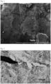
- Fig. 1 is an enlarged photograph of a fracture surface of a cracked portion in a continuously cast slab shot with a scanning electron microscope (SEM).
- SEM scanning electron microscope
- the fracture surface exhibits an intergranular fracture surface along a prior austenite grain boundary.
- Fig. 2 shows a micrograph of a cross-section of the cracked portion, in which the depth of the crack from the surface layer of the slab is mostly about 20 mm.
- the crack has propagated around the prior austenite grain boundary, and grain-boundary ferrite is present at the tip end of the cracked portion. Further, pearlite or pearlite and bainite is/are observed in prior austenite grains.
- An intergranular fracture occurs when prior austenite grains are coarse and their grain boundary is embrittled. Precipitates and ferrite are more likely to be formed at grain boundaries than within grains. Precipitates at grain boundaries are a factor that reduces the grain boundary strength and also reduces the toughness. When the prior austenite grains are coarse, the ratio of their grain boundaries is low, and the density of precipitates at the grain boundaries is correspondingly high, so that the grain boundaries are further embrittled. When grain-boundary ferrite is formed, there is a difference in strength between the grain-boundary ferrite and the pearlite and bainite in the grains, causing stress concentration at the grain-boundary ferrite portion with lower strength. This can lead to cracks even with lower stress.
- Patent Literature 1 discloses a method for suppressing bainite/martensitic transformation by slowly cooling from 700 to 500°C, the temperature range in which the transformation of austenite to ferrite occurs, thereby reducing stress generated due to the transformation expansion.
- Patent Literature 2 discloses a method for reducing a temperature difference and reducing stress due to transformation by starting the slow cooling immediately after casting, then slowly cooling at a temperature of 700°C or higher for 10 hours or longer and further from 700 to 500°C.
- Patent Literature 1 and Patent Literature 2 have the following problems.
- the method described in each of Patent Literature 1 and Patent Literature 2 of cooling a slab for high tensile strength steel after casting the slab involves controlling the cooling rate so as to reduce the internal stress to be generated in the slab.
- the toughness of a slab for high-strength steel with a higher amount of alloy added produced in recent years is low, the condition of prior austenite grain boundaries around which thermal cracking propagates is also quite important.
- Each of the methods described in Patent Literature 1 and Patent Literature 2 does not include controlling the grain size of prior austenite or the grain-boundary ferrite nor does it limit the microstructure of the slab.
- the present inventors have found that the toughness of a slab with high C, Si, and Mn contents produced with the conventional technologies is significantly low and that it is therefore impossible to sufficiently suppress the occurrence of thermal cracking in such a slab.
- the present invention has been made in view of the above circumstances, and it is an object of the present invention to provide a continuously cast slab that prevents cracking during cooling of the slab, even when the slab is a high-alloy slab with low toughness.
- the inventors have conducted extensive studies in order to achieve the above object. As a result, by analyzing the fracture morphology of slab cracking, the inventors found that its fracture surface includes at least one type selected from an intergranular fracture surface along a prior austenite grain boundary and an intragranular fracture surface (a cleavage fracture surface) across a prior austenite grain boundary. Through various detailed studies, the inventors further found that it is impossible to suppress the occurrence of thermal cracking in a slab only by reducing the stress achieved by controlling the cooling rate and reducing the temperature variation, and that the morphology of the microstructure of the slab has a great influence on the occurrence of thermal cracking.
- the inventors found that it is possible to suppress the occurrence of thermal cracking in a continuously cast slab during cooling, by controlling the average prior austenite grain size and microstructure of the continuously cast slab to increase the toughness of the slab, and thus arrived at the present invention.
- the gist and the features of the present invention are as follows.
- the present invention can provide a continuously cast slab that prevents the occurrence of cracking during a cooling process even when the slab has an ingredient composition of a high-alloy, high-strength steel sheet.
- the average prior austenite grain size is a factor that determines the unit of a fracture.
- the average prior austenite grain size is as large as several millimeters. This significantly reduces the toughness of the continuously cast slab.
- the average prior austenite grain size is not a concern. Meanwhile, for high-alloy, high-strength steel, the average prior austenite grain size can be a major concern.
- the average prior austenite grain size at a position 10 mm from the surface layer of the continuously cast slab is set in the range of 100 ⁇ m to 0.5 mm.
- a factor determining the austenite grain size is the cooling temperature, and for example, it is possible to refine the average prior austenite grain size at a position 10 mm from the surface layer of the continuously cast slab by rapidly cooling the slab surface to the Bs point or lower while the surface temperature of the center of the wide face of the slab is in the range of 1200°C to 900°C, followed by stopping the cooling, and then reheating the slab to the Ac3 point or higher. Furthermore, it is preferable to perform cooling such that the slab is retained in the temperature range of 1450 to 1200°C for 40 seconds to 130 seconds.
- a temperature history at a position 10 mm below the surface layer of the continuously cast slab was calculated by heat-transfer analysis.
- the position for heat-transfer analysis was set at the center of the wide face of the slab. Note that the average prior austenite grain size is preferably 0.4 mm or less.
- the ratio of internal components such as ferrite, pearlite, and bainite are also factors determining the unit of a fracture, and it is known that controlling these ratios to be within appropriate ranges can increase the toughness.
- the microstructure of the slab is greatly influenced by the cooling rate at the temperature (Ar 3 temperature) at which transformation from austenite to ferrite occurs or below.
- the inventors have found that it is possible to increase the toughness of a steel slab by controlling the cooling rate so as to obtain a microstructure in which the area ratio of ferrite is 10% or more, the area ratio of pearlite is 10% or more, and the area ratio of bainite is in the range of 1% to 30%.
- the area ratio of bainite is in the range of 5% to 30%.
- the cooling rate for controlling the microstructure in the above manner largely varies depending on the steel component. Therefore, a continuous cooling transformation diagram (CCT diagram) for steel with the components was prepared to determine the cooling rate for obtaining the preferred microstructure.
- CCT diagram continuous cooling transformation diagram
- the cooling conditions can be controlled by changing conditions such as the temperature of the slab on the exit side of the continuous casting machine, the time taken to stack slabs, the number of slabs to be stacked, and a water-toughening process, for example.
- the cooling rate was measured with a thermocouple. Specifically, the thermocouple was disposed at the central portion (the center in the longitudinal direction and the center in the width direction) of the upper surface of a wide face (the longer side ⁇ width) of the slab removed from the continuous casting machine.
- the toughness of a continuously cast slab with high C, Si, and Mn contents is significantly low.
- the C content is an important element in increasing the strength of a steel sheet. If the C content is less than 0.10%, it is difficult to achieve the tensile strength required for a steel sheet. Meanwhile, if the C content is over 0.40%, it is impossible to obtain a microstructure containing ferrite, pearlite, and bainite in a mixed manner as described above. Thus, the C content is set in the range of 0.10 to 0.40%. It is preferably 0.12 or more. It is preferably 0.35% or less. It is more preferably 0.15% or more. It is more preferably 0.30% or less.
- Si is required to be added to secure the residual austenite in an annealing step.
- Si is an essential additional element as it contributes to increasing the strength through solid-solution strengthening.
- Si is required to be added in an amount of 0.10% or more.
- the Si content is set in the range of 0.10 to 2.50%.
- the Si content is 0.50% or more. It is preferably 2.0% or less. It is more preferably 1.00% or more. It is more preferably 1.80% or less.
- Mn is an element added to increase the strength of a steel sheet. Specifically, Mn is an element added to control the strength of a steel sheet by controlling transformation during hot rolling. If the Mn content is less than 1.00%, it is impossible to sufficiently reinforce the steel sheet. Thus, Mn needs to be added by 1.00% or more. Meanwhile, if Mn is added by more than 5.00%, the above effect is saturated, lowering cost efficiency. Therefore, the Mn content is set in the range of 1.00 to 5.00%. It is preferably 1.50% or more. It is preferably 4.50% or less. It is more preferably 1.80% or more. It is more preferably 4.00% or less.
- the continuously cast slab of this embodiment has the above ingredient composition with the balance being Fe and unavoidable impurities.
- the continuously cast slab has the average prior austenite grain size in an appropriate range and a microstructure in an appropriate range.
- the continuously cast slab may also contain, with other properties taken into consideration, 0.100% or less P, 0.0200% or less S, 0.0100% or less N, 0.100% or less sol. Al, and 0.0100% or less O.
- the impurities herein include Zn, Pb, and As. The total content of such unavoidable impurities is allowed to be 0.100% or less.
- the P content is preferably set to 0.100% or less. Note that the lower limit of the P content is not specified. However, since P is a solid-solution strengthening element and increases the strength of the steel sheet, the P content is preferably set to 0.001% or more. Thus, the P content is preferably set to 0.100% or less. It is preferably 0.001% or more. It is further preferably 0.070% or less.
- the S content is present as sulfide and causes the embrittlement of the slab.
- the S content is preferably set to 0.0200% or less. Note that the lower limit of the S content is not specified. However, the S content is preferably set to 0.0001% or more due to the restrictions of the production technology. Thus, the S content is preferably set to 0.0200% or less. It is preferably 0.0001% or more. It is more preferably 0.0050% or less.
- Al affects the fraction of the residual austenite in the slab by suppressing the generation of carbide and promoting the formation of the residual austenite while the slab is cooled.
- Al is preferably added by 0.005% or more for deoxidation. If the Al content exceeds 0.100%, the slab may become brittle. Thus, the Al content is preferably set to 0.100% or less. It is more preferably 0.010% or more. It is more preferably 0.080% or less.
- the N content is present as nitride and causes the embrittlement of the slab. Therefore, the N content is preferably set to 0.0100% or less. Note that the lower limit of the N content is not specified. However, the N content is preferably set to 0.0001% or more due to the restrictions of the production technology. Thus, the N content is preferably set to 0.0100% or less. It is preferably 0.0001% or more. It is more preferably 0.0050% or less.
- the O content is present as oxide and causes the embrittlement of the slab. Therefore, the O content is preferably set to 0.0100% or less. Note that the lower limit of the O content is not specified. However, the O content is preferably set to 0.0001% or more due to the restrictions of the production technology. Thus, the O content is preferably set to 0.0100% or less. It is preferably 0.0001% or more. It is more preferably 0.0050% or less.
- the continuously cast slab of this embodiment may further contain, for high-strength steel, at least one element selected from the group consisting of Ti: 0.200% or less, Nb: 0.200% or less, V: 0.200% or less, Ta: 0.10% or less, W: 0.10% or less, B: 0.0100% or less, Cr: 1.00% or less, Mo: 1.00% or less, Ni: 1.00% or less, Co: 1.00% or less, Cu: 1.00% or less, Sn: 0.200% or less, Sb: 0.200% or less, Ca: 0.0100% or less, Mg: 0.0100% or less, REM: 0.0100% or less, Zr: 0.020% or less, Te: 0.020% or less, Hf: 0.10% or less, and Bi: 0.200% or less, either alone or in combination in addition to the above ingredient composition.
- Ti, Nb, and V each do not produce coarse precipitates or inclusions in large amounts and thus do not reduce the toughness of the slab, when the content of each element is 0.200% or less. Therefore, the content of each of Ti, Nb, and V is preferably set to 0.200% or less. Note that the lower limit of the content of each of Ti, Nb, and V is not specified. However, since Ti, Nb, and V form fine carbide, nitride, or carbonitride during hot rolling or continuous annealing to thus increase the strength of the steel sheet, the content of each element is preferably set to 0.001% or more. When Ti, Nb, and V are contained, the content of each element is set to 0.200% or less. It is more preferably 0.001% or more. It is further preferably 0.100% or less.
- Ta and W each do not produce coarse precipitates or inclusions in large amounts and thus do not reduce the toughness of the slab, when the content of each element is 0.10% or less. Therefore, the content of each of Ta and W is preferably set to 0.10% or less. Note that the lower limit of the content of each of Ta and W is not specified. However, since each of Ta and W forms fine carbide, nitride, or carbonitride during hot rolling or continuous annealing to thus increase the strength of the steel sheet, the content of each element is preferably 0.01% or more. Thus, when Ta and W are contained, the content of each element is preferably 0.10% or less. It is more preferably 0.01% or more. It is further preferably 0.08% or less.
- the B content does not affect the toughness of the slab, when the B content is 0.0100% or less. Therefore, it is preferable to set the B content to 0.0100% or less.
- the lower limit of the B content is not specified.
- the B content is preferably set to 0.0003% or more because B is segregated at austenite grain boundaries during hot rolling and annealing and thus increases hardenability.
- the B content is set to 0.0100% or less. It is more preferably 0.0003% or more. It is further preferably 0.0080% or less.
- Cr, Mo, and Ni each do not increase coarse precipitates or inclusions and thus do not reduce the toughness of the slab, when the content of each element is 1.00% or less. Therefore, the content of each of Cr, Mo, and Ni is preferably set to 1.00% or less. Note that the lower limit of the content of each of Cr, Mo, and Ni is not specified. However, since Cr, Mo, and Ni increase hardenability, the content of each element is preferably set to 0.01% or more. Thus, when Cr, Mo, and Ni are contained, the content of each element is set to 1.00% or less. It is more preferably 0.01% or more. It is further preferably 0.80% or less.
- Co does not increase coarse precipitates or inclusions and thus does not reduce the toughness of the slab, when the content of Co is 1.00% or less. Therefore, the Co content is preferably set to 1.00% or less. Note that the lower limit of the Co content is not specified. However, the Co content is preferably set to 0.001% or more because Co increases hardenability. Thus, when Co is contained, the Co content is set to 1.00% or less. It is more preferably 0.001% or more. It is further preferably 0.80% or less.
- the Cu content is preferably set to 1.00% or less.
- the lower limit of the Cu content is not specified.
- the Cu content is preferably set to 0.01% or more because Cu is an element that increases hardenability.
- the Cu content is set to 1.00% or less. It is more preferably 0.01% or more. It is further preferably 0.80% or less.
- the Sn content is preferably set to 0.200% or less.
- the lower limit of the Sn content is not specified.
- the Sn content is preferably set to 0.001% or more because Sn increases hardenability (an element that typically increases corrosion resistance).
- the Sn content is set to 0.200% or less. It is more preferably 0.001% or more. It is further preferably 0.100% or less.
- the Sb content is preferably set to 0.200% or less.
- the lower limit of the Sb content is not specified.
- the Sb content is preferably set to 0.001% or more because Sb suppresses decarburization and allow the strength of the steel sheet to be adjusted.
- the Sb content is set to 0.200% or less. It is more preferably 0.001% or more. It is further preferably 0.100% or less.
- Ca, Mg, and REM each do not increase coarse precipitates or inclusions and thus do not reduce the toughness of the slab, when the content of each element is 0.0100% or less. Therefore, the content of each of Ca, Mg, and REM is preferably set to 0.0100% or less. Note that the lower limit of the content of each of Ca, Mg, and REM is not specified. However, the content of each of Ca, Mg, and REM is preferably set to 0.0005% or more because these elements make the forms of nitride and sulfide spherical and increase the toughness of the slab. Thus, when Ca, Mg, and REM are contained, the content of each element is set to 0.0100% or less. It is more preferably 0.0005% or more. It is further preferably 0.0050% or less.
- Zr and Te each do not increase coarse precipitates or inclusions and thus do not reduce the toughness of the slab, when the content of each element is 0.100% or less. Therefore, the content of each of Zr and Te is preferably set to 0.100% or less. Note that the lower limit of the content of each of Zr and Te is not specified. However, the content of each of Zr and Te is preferably set to 0.001% or more because these elements make the forms of nitride and sulfide spherical and increase the toughness of the slab. Thus, when Zr and Te are contained, the content of each element is set to 0.100% or less. It is more preferably 0.001% or more. It is further preferably 0.080% or less.
- the Hf content is preferably set to 0.10% or less.
- the lower limit of the Hf content is not specified.
- the Hf content is preferably set to 0.01% or more because Hf makes the forms of nitride and sulfide spherical, and improves the ultimate deformability of the steel sheet.
- the Hf content is set to 0.10% or less. It is more preferably 0.01% or more. It is further preferably 0.08% or less.
- the Bi content is preferably set to 0.200% or less.
- the lower limit of the Bi content is not specified.
- the Bi content is preferably set to 0.001% or more because Bi reduces segregation.
- the Bi content is set to 0.200% or less. It is more preferably 0.001% or more. It is further preferably 0.100% or less.
- each element may be included as unavoidable impurities, because each element does not impair the advantageous effects of the present invention, when the content of each element is less than its preferred lower limit.
- the average prior austenite grain size was measured as follows. A sample was cut out of the position of the center of the wide face of the slab subjected to cooling such that a slab thickness cross section parallel to the width direction of the slab was used as observed face. The observation face was then subjected to mirror polishing with diamond paste, followed by finish polishing with colloidal silica, and was further etched with 3 vol.% Nital to expose the structure on the observation face. The sample was then observed at a position 10 mm from the surface layer of the slab at 10x magnification for five visual fields, using an optical microscope to obtain structure images of the continuously cast slab. The average value of the prior austenite grain sizes was obtained from the obtained structure images by a cutting method according to JIS G 0551:2020.
- an observation face of each slab was prepared as in the above method of measuring the average prior austenite grain size.
- the observation face was then subjected to mirror polishing with diamond paste, followed by finish polishing with colloidal silica, and was further etched with 3 vol.% Nital to expose the structure.
- the sample was observed at a position 10 mm from the surface layer of the slab at 50x magnification for 10 visual fields, using a SEM (Scanning Electron Microscope) under an accelerating voltage condition of 15 kV.
- SEM Sccanning Electron Microscope
- ferrite has a larger grain size, a smoother surface, and lower contrast than other structures (i.e., pearlite, bainite, tempered martensite, quenched martensite, and residual austenite), and thus can be easily distinguished at 50x magnification.
- a method of measuring the area ratios of these structures involves exposing the structure on the observation face of each slab as in the above method of measuring the area ratio of ferrite. Then, the slab was observed at a position 10 mm from the surface layer of the slab at 10000x magnification for 10 visual fields using the SEM under an accelerating voltage condition of 15 kV while ferrite was excluded from the visual fields. From the obtained structure images, the area ratios of pearlite and the area ratios of bainite were calculated for the 10 visual fields using PHOTOSHOP (registered trademark) of Adobe Inc. Then, the average of the obtained values was determined as the area ratio of each structure through calculation such that the total area ratio including the area ratio of each structure and the area ratio of ferrite measured with the above method reached 100%. Bainite is a structure of a recessed portion, and pearlite is a structure of a recessed portion that contains lamellar carbide.
- Table 1 shows the chemical compositions of steel used for the studies.
- Table 2 shows the cooling conditions for each slab, the microstructure of the slab, and the aspect of cracking in the slab.
- Symbols F, P, and B in the field of the microstructure represent ferrite, pearlite, and bainite, respectively.
- Test Nos. 1 to 4 correspond to the condition in which the average prior austenite grain size at a position 10 mm below the surface layer of the continuously cast slab exceeded 0.5 mm. In such cases, it was impossible to suppress the occurrence of cracking in the slab even if the conditions for cooling the slab after removal from the continuous casting machine were varied.
- Test Nos. 5 to 9 correspond to the examples in which the average prior austenite grain size at a position 10 mm below the surface layer of the continuously cast slab is 0.5 mm or less while the type of the microstructure or the ratio thereof does not match the condition of the present invention, and it was thus impossible to suppress the occurrence of cracking in the slab.
- Test Nos. 10 to 23 correspond to Invention Examples in which the average prior austenite grain size at a position 10 mm below the surface layer of the continuously cast slab is 0.5 mm or less and the area ratio of ferrite is 10% or more, the area ratio of pearlite is 10% or more, and the area ratio of bainite is in the range of 1% to 30% in the microstructure of the slab. No cracking occurred in these cases after a cooling process.
- the continuously cast slab according to the present invention may require re-stacking depending on various conditions.
- the cooling rate for the continuously cast slab may temporarily exceed a predetermined cooling rate.
- the average cooling rate is defined as a cooling condition instead of the maximum cooling rate.
- Such a slab structure can be obtained, for example, by rapidly cooling the slab surface to the Bs point or lower when the surface temperature of the center of the wide face of the slab is in the range of 900°C to 1200°C, followed by stopping the cooling, so that the temperature reaches to the Ac 3 point or higher, and further setting each of the average cooling rates when the surface temperature of the center of the wide face of the slab is in the range of 850°C to 700°C and in the range of 700°C to 500°C to a predetermined range.
- the production method is not limited thereto.
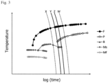
- Fig. 3 illustrates a method for determining the cooling rate for obtaining the preferred microstructure.
- Fig. 3 is a continuous cooling transformation diagram (i.e., a CCT diagram) of steel C in Table 1.
- a transformation start line of ferrite, a transformation start line of pearlite, a transformation start line of bainite, a transformation start line of martensite, and a transformation end line of martensite are indicated by reference signs F, P, B, Ms, and Mf, respectively.
- cooling rate lines are indicated by reference signs X, Y, Z, and W in descending order of the cooling rate.
- the present invention is industrially advantageous.
Landscapes
- Chemical & Material Sciences (AREA)
- Engineering & Computer Science (AREA)
- Mechanical Engineering (AREA)
- Materials Engineering (AREA)
- Metallurgy (AREA)
- Organic Chemistry (AREA)
- Physics & Mathematics (AREA)
- Thermal Sciences (AREA)
- Crystallography & Structural Chemistry (AREA)
- Continuous Casting (AREA)
- Heat Treatment Of Steel (AREA)
Abstract
Description
- The present invention relates to a continuously cast slab that prevents cracking during a cooling process.
- In recent years, the automotive industry has been developing high-strength steels with higher strength and higher alloying levels therefor in order to further reduce the thickness of car bodies and improve crash safety. Increasing the level of alloying has resulted in a significant reduction in the toughness of a slab.
- As the toughness of a slab decreases with an increase in the alloying level, cracking in the slab during cooling, known as "thermal cracking", in other words, "season cracking", has occurred more frequently. Such thermal cracking causes the slab to fracture while being conveyed, preventing the slab from being hot rolled. Even if the slab does not fracture, the cracks may open during hot rolling, causing the resulting hot-rolled steel sheet to fracture. Meanwhile, small cracks in a slab appear as surface defects, such as scabs or slivers, on the resulting steel sheet after hot rolling, cold rolling, annealing, or plating. Typically, cracks in the surface of a slab are removed with a grinder. However, in a case where the toughness of the slab has decreased with an increase in the amount of alloy added and the cracks in the slab develop due to the stress applied by the grinder, it may be impossible to remove the cracks in the slab completely. Furthermore, small cracks in the slab may be overlooked and appear as surface defects on the resulting steel sheet after hot rolling, cold rolling, annealing, or plating. For the above reasons, it is necessary to suppress cracking in slabs.
-
Fig. 1 is an enlarged photograph of a fracture surface of a cracked portion in a continuously cast slab shot with a scanning electron microscope (SEM). The fracture surface exhibits an intergranular fracture surface along a prior austenite grain boundary.Fig. 2 shows a micrograph of a cross-section of the cracked portion, in which the depth of the crack from the surface layer of the slab is mostly about 20 mm. The crack has propagated around the prior austenite grain boundary, and grain-boundary ferrite is present at the tip end of the cracked portion. Further, pearlite or pearlite and bainite is/are observed in prior austenite grains. - An intergranular fracture occurs when prior austenite grains are coarse and their grain boundary is embrittled. Precipitates and ferrite are more likely to be formed at grain boundaries than within grains. Precipitates at grain boundaries are a factor that reduces the grain boundary strength and also reduces the toughness. When the prior austenite grains are coarse, the ratio of their grain boundaries is low, and the density of precipitates at the grain boundaries is correspondingly high, so that the grain boundaries are further embrittled. When grain-boundary ferrite is formed, there is a difference in strength between the grain-boundary ferrite and the pearlite and bainite in the grains, causing stress concentration at the grain-boundary ferrite portion with lower strength. This can lead to cracks even with lower stress. In such a case, when the prior austenite grains are coarse, grain-boundary ferrite that is linearly thin and elongated is precipitated, making it difficult to avoid the propagation of the cracks, resulting in an increased damage. Meanwhile, when the slab is cooled, stress is caused due to the difference in thermal shrinkage or in transformation expansion between the surface and the inside of the slab. When the stress is high, cracks are caused in the slab while the slab is cooled to room temperature. Since the toughness of a slab for high-alloy, high-strength steel produced in recent years is low, it has been difficult to remove deep cracks that have occurred in the slab in the above manner by using some measures such as a grinder. This has been a problem that greatly reduced the yield of the slab.
- In this regard, countermeasures against cracking in a slab have been studied as disclosed in Patent Literature 1 and Patent Literature 2, for example. Patent Literature 1 discloses a method for suppressing bainite/martensitic transformation by slowly cooling from 700 to 500°C, the temperature range in which the transformation of austenite to ferrite occurs, thereby reducing stress generated due to the transformation expansion. Patent Literature 2 discloses a method for reducing a temperature difference and reducing stress due to transformation by starting the slow cooling immediately after casting, then slowly cooling at a temperature of 700°C or higher for 10 hours or longer and further from 700 to 500°C.
-
- Patent Literature 1:
JP-2020-139209A - Patent Literature 2:
JP-2019-167560A - However, the conventional technologies have the following problems. The method described in each of Patent Literature 1 and Patent Literature 2 of cooling a slab for high tensile strength steel after casting the slab involves controlling the cooling rate so as to reduce the internal stress to be generated in the slab. However, since the toughness of a slab for high-strength steel with a higher amount of alloy added produced in recent years is low, the condition of prior austenite grain boundaries around which thermal cracking propagates is also quite important. Each of the methods described in Patent Literature 1 and Patent Literature 2, however, does not include controlling the grain size of prior austenite or the grain-boundary ferrite nor does it limit the microstructure of the slab. As a result of conducting intensive studies, the present inventors have found that the toughness of a slab with high C, Si, and Mn contents produced with the conventional technologies is significantly low and that it is therefore impossible to sufficiently suppress the occurrence of thermal cracking in such a slab.
- The present invention has been made in view of the above circumstances, and it is an object of the present invention to provide a continuously cast slab that prevents cracking during cooling of the slab, even when the slab is a high-alloy slab with low toughness.
- The inventors have conducted extensive studies in order to achieve the above object. As a result, by analyzing the fracture morphology of slab cracking, the inventors found that its fracture surface includes at least one type selected from an intergranular fracture surface along a prior austenite grain boundary and an intragranular fracture surface (a cleavage fracture surface) across a prior austenite grain boundary. Through various detailed studies, the inventors further found that it is impossible to suppress the occurrence of thermal cracking in a slab only by reducing the stress achieved by controlling the cooling rate and reducing the temperature variation, and that the morphology of the microstructure of the slab has a great influence on the occurrence of thermal cracking. Specifically, the inventors found that it is possible to suppress the occurrence of thermal cracking in a continuously cast slab during cooling, by controlling the average prior austenite grain size and microstructure of the continuously cast slab to increase the toughness of the slab, and thus arrived at the present invention.
- The present invention has been completed based on the above findings with further studies conducted thereon.
- That is, the gist and the features of the present invention are as follows.
- 1. A continuously cast slab for high-strength steel, characterized in that an average prior austenite grain size at a position 10 mm from a surface layer of the continuously cast slab is in a range of 100 µm to 0.5 mm, and that in a microstructure, an area ratio of ferrite is 10% or more, an area ratio of pearlite is 10% or more, and an area ratio of bainite is in a range of 1% to 30%.
- 2. The continuously cast slab according to 1, including, in mass%, C: in a range of 0.10 to 0.40%, Si: in a range of 0.10 to 2.50%, and Mn: in a range of 1.00 to 5.00%.
- The present invention can provide a continuously cast slab that prevents the occurrence of cracking during a cooling process even when the slab has an ingredient composition of a high-alloy, high-strength steel sheet.
-
- [
Fig. 1] Fig. 1 is an image of a fracture surface of a cracked portion in a continuously cast slab observed with a scanning electron microscope. - [
Fig. 2] Fig. 2 is a micrograph of a cross-sectional structure of the above cracked portion. - [
Fig. 3] Fig. 3 is a graph representing the cooling rate for a continuously cast slab and the microstructure of the slab on a continuous cooling transformation diagram (CCT diagram). - Hereinafter, embodiments of the present invention will be specifically described. The following embodiments only illustrate examples of the composition and the structure of steel to embody the technical idea of the present invention. Thus, the configuration of the present invention is not limited thereto. That is, the technical idea of the present invention can be modified in various ways within the technical scope recited in the claims.
- First, an appropriate range of the microstructure of the continuously cast slab, and reasons for limiting such a range will be described. In the following description, the symbol "%" representing a constitutional ratio in the microstructure means "area %" unless otherwise stated. The structure has been observed at room temperature.
- The average prior austenite grain size is a factor that determines the unit of a fracture. The larger the average prior austenite grain size, the lower the toughness of a slab, causing cracking in the slab such that it exhibits an intergranular fracture surface. In the conventional continuously cast slab, the average prior austenite grain size is as large as several millimeters. This significantly reduces the toughness of the continuously cast slab. For the conventional low-alloy steel, which originally has high toughness, the average prior austenite grain size is not a concern. Meanwhile, for high-alloy, high-strength steel, the average prior austenite grain size can be a major concern. In this embodiment, therefore, the average prior austenite grain size at a position 10 mm from the surface layer of the continuously cast slab is set in the range of 100 µm to 0.5 mm. A factor determining the austenite grain size is the cooling temperature, and for example, it is possible to refine the average prior austenite grain size at a position 10 mm from the surface layer of the continuously cast slab by rapidly cooling the slab surface to the Bs point or lower while the surface temperature of the center of the wide face of the slab is in the range of 1200°C to 900°C, followed by stopping the cooling, and then reheating the slab to the Ac3 point or higher. Furthermore, it is preferable to perform cooling such that the slab is retained in the temperature range of 1450 to 1200°C for 40 seconds to 130 seconds. The above temperatures are difficult to directly measure. Therefore, a temperature history at a position 10 mm below the surface layer of the continuously cast slab was calculated by heat-transfer analysis. To maximize the retention time within the temperature range in the interior of the slab, the position for heat-transfer analysis was set at the center of the wide face of the slab. Note that the average prior austenite grain size is preferably 0.4 mm or less.
- Other than the austenite grains, the ratio of internal components such as ferrite, pearlite, and bainite are also factors determining the unit of a fracture, and it is known that controlling these ratios to be within appropriate ranges can increase the toughness. The microstructure of the slab is greatly influenced by the cooling rate at the temperature (Ar3 temperature) at which transformation from austenite to ferrite occurs or below. The inventors have found that it is possible to increase the toughness of a steel slab by controlling the cooling rate so as to obtain a microstructure in which the area ratio of ferrite is 10% or more, the area ratio of pearlite is 10% or more, and the area ratio of bainite is in the range of 1% to 30%. Preferably, the area ratio of bainite is in the range of 5% to 30%.
- The cooling rate for controlling the microstructure in the above manner largely varies depending on the steel component. Therefore, a continuous cooling transformation diagram (CCT diagram) for steel with the components was prepared to determine the cooling rate for obtaining the preferred microstructure.
- The cooling conditions can be controlled by changing conditions such as the temperature of the slab on the exit side of the continuous casting machine, the time taken to stack slabs, the number of slabs to be stacked, and a water-toughening process, for example. The cooling rate was measured with a thermocouple. Specifically, the thermocouple was disposed at the central portion (the center in the longitudinal direction and the center in the width direction) of the upper surface of a wide face (the longer side × width) of the slab removed from the continuous casting machine.
- The toughness of a continuously cast slab with high C, Si, and Mn contents is significantly low. Thus, it is impossible to secure the toughness of the slab that is sufficiently high to prevent the occurrence of thermal cracking therein by performing control to satisfy only the requirement of the average prior austenite grain size or only the requirement of the type of the microstructure, resulting in the occurrence of thermal cracking in the slab. Therefore, it is important that the continuously cast slab for high-strength steel according to this embodiment satisfies the requirements of both the average prior austenite grain size and the microstructure.
- Next, an appropriate range of the ingredient composition, and reasons for limiting the range will be described. In the following description, the symbol "%" representing the content of a constituent element of steel means "mass%" unless otherwise stated.
- C is an important element in increasing the strength of a steel sheet. If the C content is less than 0.10%, it is difficult to achieve the tensile strength required for a steel sheet. Meanwhile, if the C content is over 0.40%, it is impossible to obtain a microstructure containing ferrite, pearlite, and bainite in a mixed manner as described above. Thus, the C content is set in the range of 0.10 to 0.40%. It is preferably 0.12 or more. It is preferably 0.35% or less. It is more preferably 0.15% or more. It is more preferably 0.30% or less.
- Si is required to be added to secure the residual austenite in an annealing step. Besides, Si is an essential additional element as it contributes to increasing the strength through solid-solution strengthening. Thus, Si is required to be added in an amount of 0.10% or more. Meanwhile, if Si is added by more than 2.50%, the above effect is saturated, and also, rigid scale is formed on a hot-rolled sheet. This results in poor appearance and pickling properties of the sheet. Thus, the upper limit of the Si content is set to 2.50%. Therefore, the Si content is set in the range of 0.10 to 2.50%. Preferably, the Si content is 0.50% or more. It is preferably 2.0% or less. It is more preferably 1.00% or more. It is more preferably 1.80% or less.
- Mn is an element added to increase the strength of a steel sheet. Specifically, Mn is an element added to control the strength of a steel sheet by controlling transformation during hot rolling. If the Mn content is less than 1.00%, it is impossible to sufficiently reinforce the steel sheet. Thus, Mn needs to be added by 1.00% or more. Meanwhile, if Mn is added by more than 5.00%, the above effect is saturated, lowering cost efficiency. Therefore, the Mn content is set in the range of 1.00 to 5.00%. It is preferably 1.50% or more. It is preferably 4.50% or less. It is more preferably 1.80% or more. It is more preferably 4.00% or less.
- The continuously cast slab of this embodiment has the above ingredient composition with the balance being Fe and unavoidable impurities. In addition, the continuously cast slab has the average prior austenite grain size in an appropriate range and a microstructure in an appropriate range. Under such conditions, the continuously cast slab may also contain, with other properties taken into consideration, 0.100% or less P, 0.0200% or less S, 0.0100% or less N, 0.100% or less sol. Al, and 0.0100% or less O. Examples of the impurities herein include Zn, Pb, and As. The total content of such unavoidable impurities is allowed to be 0.100% or less.
- P is segregated on prior austenite grain boundaries and therefore may cause the embrittlement of the grain boundaries, resulting in thermal cracking in the slab in some cases. Therefore, the P content is preferably set to 0.100% or less. Note that the lower limit of the P content is not specified. However, since P is a solid-solution strengthening element and increases the strength of the steel sheet, the P content is preferably set to 0.001% or more. Thus, the P content is preferably set to 0.100% or less. It is preferably 0.001% or more. It is further preferably 0.070% or less.
- S is present as sulfide and causes the embrittlement of the slab. Thus, the S content is preferably set to 0.0200% or less. Note that the lower limit of the S content is not specified. However, the S content is preferably set to 0.0001% or more due to the restrictions of the production technology. Thus, the S content is preferably set to 0.0200% or less. It is preferably 0.0001% or more. It is more preferably 0.0050% or less.
- Al affects the fraction of the residual austenite in the slab by suppressing the generation of carbide and promoting the formation of the residual austenite while the slab is cooled. Al is preferably added by 0.005% or more for deoxidation. If the Al content exceeds 0.100%, the slab may become brittle. Thus, the Al content is preferably set to 0.100% or less. It is more preferably 0.010% or more. It is more preferably 0.080% or less.
- N is present as nitride and causes the embrittlement of the slab. Therefore, the N content is preferably set to 0.0100% or less. Note that the lower limit of the N content is not specified. However, the N content is preferably set to 0.0001% or more due to the restrictions of the production technology. Thus, the N content is preferably set to 0.0100% or less. It is preferably 0.0001% or more. It is more preferably 0.0050% or less.
- O is present as oxide and causes the embrittlement of the slab. Therefore, the O content is preferably set to 0.0100% or less. Note that the lower limit of the O content is not specified. However, the O content is preferably set to 0.0001% or more due to the restrictions of the production technology. Thus, the O content is preferably set to 0.0100% or less. It is preferably 0.0001% or more. It is more preferably 0.0050% or less.
- The continuously cast slab of this embodiment may further contain, for high-strength steel, at least one element selected from the group consisting of Ti: 0.200% or less, Nb: 0.200% or less, V: 0.200% or less, Ta: 0.10% or less, W: 0.10% or less, B: 0.0100% or less, Cr: 1.00% or less, Mo: 1.00% or less, Ni: 1.00% or less, Co: 1.00% or less, Cu: 1.00% or less, Sn: 0.200% or less, Sb: 0.200% or less, Ca: 0.0100% or less, Mg: 0.0100% or less, REM: 0.0100% or less, Zr: 0.020% or less, Te: 0.020% or less, Hf: 0.10% or less, and Bi: 0.200% or less, either alone or in combination in addition to the above ingredient composition.
- Ti, Nb, and V each do not produce coarse precipitates or inclusions in large amounts and thus do not reduce the toughness of the slab, when the content of each element is 0.200% or less. Therefore, the content of each of Ti, Nb, and V is preferably set to 0.200% or less. Note that the lower limit of the content of each of Ti, Nb, and V is not specified. However, since Ti, Nb, and V form fine carbide, nitride, or carbonitride during hot rolling or continuous annealing to thus increase the strength of the steel sheet, the content of each element is preferably set to 0.001% or more. When Ti, Nb, and V are contained, the content of each element is set to 0.200% or less. It is more preferably 0.001% or more. It is further preferably 0.100% or less.
- Ta and W each do not produce coarse precipitates or inclusions in large amounts and thus do not reduce the toughness of the slab, when the content of each element is 0.10% or less. Therefore, the content of each of Ta and W is preferably set to 0.10% or less. Note that the lower limit of the content of each of Ta and W is not specified. However, since each of Ta and W forms fine carbide, nitride, or carbonitride during hot rolling or continuous annealing to thus increase the strength of the steel sheet, the content of each element is preferably 0.01% or more. Thus, when Ta and W are contained, the content of each element is preferably 0.10% or less. It is more preferably 0.01% or more. It is further preferably 0.08% or less.
- B does not affect the toughness of the slab, when the B content is 0.0100% or less. Therefore, it is preferable to set the B content to 0.0100% or less. Note that the lower limit of the B content is not specified. However, the B content is preferably set to 0.0003% or more because B is segregated at austenite grain boundaries during hot rolling and annealing and thus increases hardenability. Thus, when B is contained, the B content is set to 0.0100% or less. It is more preferably 0.0003% or more. It is further preferably 0.0080% or less.
- Cr, Mo, and Ni each do not increase coarse precipitates or inclusions and thus do not reduce the toughness of the slab, when the content of each element is 1.00% or less. Therefore, the content of each of Cr, Mo, and Ni is preferably set to 1.00% or less. Note that the lower limit of the content of each of Cr, Mo, and Ni is not specified. However, since Cr, Mo, and Ni increase hardenability, the content of each element is preferably set to 0.01% or more. Thus, when Cr, Mo, and Ni are contained, the content of each element is set to 1.00% or less. It is more preferably 0.01% or more. It is further preferably 0.80% or less.
- Co does not increase coarse precipitates or inclusions and thus does not reduce the toughness of the slab, when the content of Co is 1.00% or less. Therefore, the Co content is preferably set to 1.00% or less. Note that the lower limit of the Co content is not specified. However, the Co content is preferably set to 0.001% or more because Co increases hardenability. Thus, when Co is contained, the Co content is set to 1.00% or less. It is more preferably 0.001% or more. It is further preferably 0.80% or less.
- Cu does not increase coarse precipitates or inclusions and thus does not reduce the toughness of the slab, when the content of Cu is 1.00% or less. Therefore, the Cu content is preferably set to 1.00% or less. Note that the lower limit of the Cu content is not specified. However, the Cu content is preferably set to 0.01% or more because Cu is an element that increases hardenability. Thus, when Cu is contained, the Cu content is set to 1.00% or less. It is more preferably 0.01% or more. It is further preferably 0.80% or less.
- Sn does not affect the toughness of the slab when the Sn content is 0.200% or less. Therefore, the Sn content is preferably set to 0.200% or less. Note that the lower limit of the Sn content is not specified. However, the Sn content is preferably set to 0.001% or more because Sn increases hardenability (an element that typically increases corrosion resistance). Thus, when Sn is contained, the Sn content is set to 0.200% or less. It is more preferably 0.001% or more. It is further preferably 0.100% or less.
- Sb does not increase coarse precipitates or inclusions and thus does not reduce the toughness of the slab, when the content of Sb is 0.200% or less. Therefore, the Sb content is preferably set to 0.200% or less. Note that the lower limit of the Sb content is not specified. However, the Sb content is preferably set to 0.001% or more because Sb suppresses decarburization and allow the strength of the steel sheet to be adjusted. Thus, when Sb is contained, the Sb content is set to 0.200% or less. It is more preferably 0.001% or more. It is further preferably 0.100% or less.
- Ca, Mg, and REM each do not increase coarse precipitates or inclusions and thus do not reduce the toughness of the slab, when the content of each element is 0.0100% or less. Therefore, the content of each of Ca, Mg, and REM is preferably set to 0.0100% or less. Note that the lower limit of the content of each of Ca, Mg, and REM is not specified. However, the content of each of Ca, Mg, and REM is preferably set to 0.0005% or more because these elements make the forms of nitride and sulfide spherical and increase the toughness of the slab. Thus, when Ca, Mg, and REM are contained, the content of each element is set to 0.0100% or less. It is more preferably 0.0005% or more. It is further preferably 0.0050% or less.
- Zr and Te each do not increase coarse precipitates or inclusions and thus do not reduce the toughness of the slab, when the content of each element is 0.100% or less. Therefore, the content of each of Zr and Te is preferably set to 0.100% or less. Note that the lower limit of the content of each of Zr and Te is not specified. However, the content of each of Zr and Te is preferably set to 0.001% or more because these elements make the forms of nitride and sulfide spherical and increase the toughness of the slab. Thus, when Zr and Te are contained, the content of each element is set to 0.100% or less. It is more preferably 0.001% or more. It is further preferably 0.080% or less.
- Hf does not increase coarse precipitates or inclusions and thus does not reduce the toughness of the slab, when the Hf content is 0.10% or less. Therefore, the Hf content is preferably set to 0.10% or less. Note that the lower limit of the Hf content is not specified. However, the Hf content is preferably set to 0.01% or more because Hf makes the forms of nitride and sulfide spherical, and improves the ultimate deformability of the steel sheet. Thus, when Hf is contained, the Hf content is set to 0.10% or less. It is more preferably 0.01% or more. It is further preferably 0.08% or less.
- Bi does not increase coarse precipitates or inclusions and thus does not reduce the toughness of the slab, when the Bi content is 0.200% or less. Therefore, the Bi content is preferably set to 0.200% or less. Note that the lower limit of the Bi content is not specified. However, the Bi content is preferably set to 0.001% or more because Bi reduces segregation. Thus, when Bi is contained, the Bi content is set to 0.200% or less. It is more preferably 0.001% or more. It is further preferably 0.100% or less.
- It should be noted that the elements Ti, Nb, V, Ta, W, B, Cr, Mo, Ni, Co, Cu, Sn, Sb, Ca, Mg, REM, Zr, Te, Hf, and Bi described above may be included as unavoidable impurities, because each element does not impair the advantageous effects of the present invention, when the content of each element is less than its preferred lower limit.
- The average prior austenite grain size was measured as follows. A sample was cut out of the position of the center of the wide face of the slab subjected to cooling such that a slab thickness cross section parallel to the width direction of the slab was used as observed face. The observation face was then subjected to mirror polishing with diamond paste, followed by finish polishing with colloidal silica, and was further etched with 3 vol.% Nital to expose the structure on the observation face. The sample was then observed at a position 10 mm from the surface layer of the slab at 10x magnification for five visual fields, using an optical microscope to obtain structure images of the continuously cast slab. The average value of the prior austenite grain sizes was obtained from the obtained structure images by a cutting method according to JIS G 0551:2020.
- For a method of measuring the area ratio of ferrite, an observation face of each slab was prepared as in the above method of measuring the average prior austenite grain size. The observation face was then subjected to mirror polishing with diamond paste, followed by finish polishing with colloidal silica, and was further etched with 3 vol.% Nital to expose the structure. Then, the sample was observed at a position 10 mm from the surface layer of the slab at 50x magnification for 10 visual fields, using a SEM (Scanning Electron Microscope) under an accelerating voltage condition of 15 kV. From the obtained structure images of the continuously cast slab, the area ratios of ferrite were calculated for the 10 visual fields using PHOTOSHOP (registered trademark) of Adobe Inc. Then, the average of the obtained values was determined as the area ratio of ferrite. Note that ferrite has a larger grain size, a smoother surface, and lower contrast than other structures (i.e., pearlite, bainite, tempered martensite, quenched martensite, and residual austenite), and thus can be easily distinguished at 50x magnification.
- A method of measuring the area ratios of these structures involves exposing the structure on the observation face of each slab as in the above method of measuring the area ratio of ferrite. Then, the slab was observed at a position 10 mm from the surface layer of the slab at 10000x magnification for 10 visual fields using the SEM under an accelerating voltage condition of 15 kV while ferrite was excluded from the visual fields. From the obtained structure images, the area ratios of pearlite and the area ratios of bainite were calculated for the 10 visual fields using PHOTOSHOP (registered trademark) of Adobe Inc. Then, the average of the obtained values was determined as the area ratio of each structure through calculation such that the total area ratio including the area ratio of each structure and the area ratio of ferrite measured with the above method reached 100%. Bainite is a structure of a recessed portion, and pearlite is a structure of a recessed portion that contains lamellar carbide.
- As a method for evaluating cracks in each slab, a test based on the penetrant test defined in JIS Z 2343:2017 was conducted to evaluate the presence or absence of a crack in the wide faces (longer side × width) and narrow faces (longer side × thickness) of the slab. After a developing solution was applied to each slab, an ooze of a penetrant was visually observed to visually check cracks in the surface of the slab.
- Table 1 shows the chemical compositions of steel used for the studies. Table 2 shows the cooling conditions for each slab, the microstructure of the slab, and the aspect of cracking in the slab. Symbols F, P, and B in the field of the microstructure represent ferrite, pearlite, and bainite, respectively.
- Test Nos. 1 to 4 correspond to the condition in which the average prior austenite grain size at a position 10 mm below the surface layer of the continuously cast slab exceeded 0.5 mm. In such cases, it was impossible to suppress the occurrence of cracking in the slab even if the conditions for cooling the slab after removal from the continuous casting machine were varied.
- Test Nos. 5 to 9 correspond to the examples in which the average prior austenite grain size at a position 10 mm below the surface layer of the continuously cast slab is 0.5 mm or less while the type of the microstructure or the ratio thereof does not match the condition of the present invention, and it was thus impossible to suppress the occurrence of cracking in the slab.
- Test Nos. 10 to 23 correspond to Invention Examples in which the average prior austenite grain size at a position 10 mm below the surface layer of the continuously cast slab is 0.5 mm or less and the area ratio of ferrite is 10% or more, the area ratio of pearlite is 10% or more, and the area ratio of bainite is in the range of 1% to 30% in the microstructure of the slab. No cracking occurred in these cases after a cooling process.
- Note that the continuously cast slab according to the present invention may require re-stacking depending on various conditions. When re-stacking is performed, the cooling rate for the continuously cast slab may temporarily exceed a predetermined cooling rate. However, since the time for transformation is as long as 10 hours or more, thermal cracking is not caused by such a handling time of the degree (1 to 2 hours at the longest) required for re-stacking. Therefore, in the present invention, the average cooling rate is defined as a cooling condition instead of the maximum cooling rate.
[Table 1] Steel Symbol Chemical Composition [mass%] c Si Mn P S sol.Al N Ti A 0.11 1.87 2.92 0.011 0.0011 0.052 0.0043 B 0.15 0.47 4.98 0.009 0.0015 0.048 0.0039 C 0.16 0.70 1.53 0.008 0.0015 0.047 0.0032 D 0.18 1.36 2.68 0.007 0.0021 0.048 0.0034 0.02 E 0.25 1.12 3.22 0.007 0.0013 0.050 0.0036 F 0.40 0.42 1.57 0.010 0.0008 0.043 0.0030 [Table 2] No. Steel Symbol Average Prior Austenite Grain Size Microstructure Cooling Rate Crack Remarks Type Area Ratio [%] 850 to 700°C 700 to 500°C mm F P B °C/hr °C/hr Present/ Absent 1 D 1.2 Grain boundary F+P+B 8 7 85 50 23 Present Comparative Example 2 D 1.3 F+P+B 21 71 8 20 15 Present Comparative Example 3 D 0.9 Grain boundary F+P+B 4 33 63 28 5 Present Comparative Example 4 D 0.8 F+P 21 79 0 13 7 Present Comparative Example 5 D 0.5 P+B 0 5 95 50 24 Present Comparative Example 6 D 0.4 Grain boundary F+P+B 7 26 67 46 13 Present Comparative Example 7 D 0.5 F+P+B 12 27 61 32 7 Present Comparative Example 8 D 0.4 F+P 22 78 0 9 7 Present Comparative Example 9 D 0.5 F+P 24 76 0 6 3 Present Comparative Example 10 D 0.4 F+P+B 15 68 17 23 16 Absent Invention Example 11 D 0.5 F+P+B 13 62 25 25 14 Absent Invention Example 12 D 0.5 F+P+B 16 76 8 19 5 Absent Invention Example 13 A 0.5 F+P+B 19 63 18 20 13 Absent Invention Example 14 A 0.4 F+P+B 17 59 24 24 12 Absent Invention Example 15 B 0.5 F+P+B 15 72 13 7 6 Absent Invention Example 16 B 0.5 F+P+B 12 63 25 8 4 Absent Invention Example 17 B 0.4 F+P+B 12 72 16 6 2 Absent Invention Example 18 C 0.5 F+P+B 61 22 17 107 58 Absent Invention Example 19 C 0.4 F+P+B 56 23 21 82 47 Absent Invention Example 20 E 0.5 F+P+B 13 75 12 31 21 Absent Invention Example 21 E 0.5 F+P+B 19 74 7 27 20 Absent Invention Example 22 F 0.5 F+P+B 21 71 8 51 29 Absent Invention Example 23 F 0.4 F+P+B 27 69 4 41 22 Absent Invention Example - In summary, it is possible to suppress the occurrence of cracking in each continuously cast slab during a cooling process by setting the average prior austenite grain size at a position 10 mm below the surface layer of the continuously cast slab to the range of 100 µm to 0.5 mm, and forming a three-phase composite structure of ferrite, pearlite, and bainite as the microstructure at the position.
- Such a slab structure can be obtained, for example, by rapidly cooling the slab surface to the Bs point or lower when the surface temperature of the center of the wide face of the slab is in the range of 900°C to 1200°C, followed by stopping the cooling, so that the temperature reaches to the Ac3 point or higher, and further setting each of the average cooling rates when the surface temperature of the center of the wide face of the slab is in the range of 850°C to 700°C and in the range of 700°C to 500°C to a predetermined range. However, the production method is not limited thereto.
-
Fig. 3 illustrates a method for determining the cooling rate for obtaining the preferred microstructure.Fig. 3 is a continuous cooling transformation diagram (i.e., a CCT diagram) of steel C in Table 1. InFig. 3 , a transformation start line of ferrite, a transformation start line of pearlite, a transformation start line of bainite, a transformation start line of martensite, and a transformation end line of martensite are indicated by reference signs F, P, B, Ms, and Mf, respectively. Further, inFig. 3 , cooling rate lines are indicated by reference signs X, Y, Z, and W in descending order of the cooling rate. It is found that three phases of ferrite, pearlite, and bainite precipitate in the range of the cooling rate lines Y to Z and that the cooling rate in such a range is preferred. However, such a diagram is preferably used just as a rough standard because it is difficult to predict the fraction of a structure that has undergone transformation from the continuous cooling transformation diagram, and also because the cooling rate for a cast slab is typically not always constant. Note that a method for creating the continuous cooling transformation diagram used herein is not limited to a particular method. Thus, such a diagram may be created either through computation with common commercially available software or through experiments. - With a continuously cast slab having a microstructure that matches the present invention, it is possible to provide a continuously cast slab for a high-alloy, high-strength steel sheet that prevents cracking after a casting process and avoids the occurrence of problems such as the formation of holes, during a rolling process. Thus, the present invention is industrially advantageous.
Claims (2)
- A continuously cast slab for high-strength steel, characterized in thatan average prior austenite grain size at a position 10 mm from a surface layer of the continuously cast slab is in a range of 100 µm to 0.5 mm, andin a microstructure, an area ratio of ferrite is 10% or more, an area ratio of pearlite is 10% or more, and an area ratio of bainite is in a range of 1% to 30%.
- The continuously cast slab according to claim 1, comprising, in mass%:C: in a range of 0.10 to 0.40%;Si: in a range of 0.10 to 2.50%; andMn: in a range of 1.00 to 5.00%.
Applications Claiming Priority (2)
| Application Number | Priority Date | Filing Date | Title |
|---|---|---|---|
| JP2022077134 | 2022-05-09 | ||
| PCT/JP2023/012738 WO2023218784A1 (en) | 2022-05-09 | 2023-03-29 | Continuous cast slab |
Publications (2)
| Publication Number | Publication Date |
|---|---|
| EP4502219A1 true EP4502219A1 (en) | 2025-02-05 |
| EP4502219A4 EP4502219A4 (en) | 2026-03-25 |
Family
ID=88730085
Family Applications (1)
| Application Number | Title | Priority Date | Filing Date |
|---|---|---|---|
| EP23803267.6A Pending EP4502219A4 (en) | 2022-05-09 | 2023-03-29 | Continuous cast plate |
Country Status (7)
| Country | Link |
|---|---|
| US (1) | US20250290181A1 (en) |
| EP (1) | EP4502219A4 (en) |
| JP (2) | JPWO2023218784A1 (en) |
| KR (1) | KR20250003817A (en) |
| CN (1) | CN119053722A (en) |
| TW (1) | TWI867495B (en) |
| WO (1) | WO2023218784A1 (en) |
Families Citing this family (1)
| Publication number | Priority date | Publication date | Assignee | Title |
|---|---|---|---|---|
| CN120769927A (en) * | 2023-04-07 | 2025-10-10 | 杰富意钢铁株式会社 | Continuous casting slab and manufacturing method thereof |
Family Cites Families (11)
| Publication number | Priority date | Publication date | Assignee | Title |
|---|---|---|---|---|
| JP3008825B2 (en) * | 1995-08-08 | 2000-02-14 | 住友金属工業株式会社 | Slab surface crack suppression method |
| JP4966547B2 (en) * | 2006-01-06 | 2012-07-04 | 住友金属工業株式会社 | Continuous casting method |
| JP4445561B2 (en) * | 2008-07-15 | 2010-04-07 | 新日本製鐵株式会社 | Continuous casting slab of steel and method for producing the same |
| CN105296846B (en) * | 2014-07-02 | 2019-11-26 | 新报国制铁株式会社 | Low thermal expansion cast steel product and its manufacturing method |
| JP7047517B2 (en) * | 2018-03-22 | 2022-04-05 | 日本製鉄株式会社 | Cooling method for slabs for high-strength steel sheets, manufacturing method for high-strength hot-rolled steel sheets, manufacturing method for high-strength hot-dip galvanized steel sheets, and manufacturing method for high-strength alloyed hot-dip galvanized steel sheets. |
| JP7047516B2 (en) * | 2018-03-22 | 2022-04-05 | 日本製鉄株式会社 | Cooling method for slabs for high-strength steel sheets, manufacturing method for high-strength hot-rolled steel sheets, manufacturing method for high-strength hot-dip galvanized steel sheets, and manufacturing method for high-strength alloyed hot-dip galvanized steel sheets. |
| JP7260335B2 (en) | 2019-02-28 | 2023-04-18 | 株式会社神戸製鋼所 | Cooling method for slabs of high-strength steel |
| JP7260336B2 (en) * | 2019-02-28 | 2023-04-18 | 株式会社神戸製鋼所 | Cooling method for slabs of high-strength steel |
| CN113825846B (en) * | 2019-05-07 | 2024-08-23 | 美国钢铁公司 | Method for producing continuous casting hot rolled high strength steel sheet products |
| CN110257723A (en) * | 2019-07-25 | 2019-09-20 | 马鞍山钢铁股份有限公司 | A kind of high silicon hot forming steel continuous casting producing method |
| CN110592497B (en) * | 2019-09-18 | 2020-05-22 | 宁波市鄞州富春精密铸造有限公司 | High-strength cast steel and preparation method thereof |
-
2023
- 2023-03-29 EP EP23803267.6A patent/EP4502219A4/en active Pending
- 2023-03-29 US US18/862,000 patent/US20250290181A1/en active Pending
- 2023-03-29 CN CN202380035314.2A patent/CN119053722A/en active Pending
- 2023-03-29 WO PCT/JP2023/012738 patent/WO2023218784A1/en not_active Ceased
- 2023-03-29 JP JP2023541323A patent/JPWO2023218784A1/ja active Pending
- 2023-03-29 KR KR1020247037782A patent/KR20250003817A/en active Pending
- 2023-04-13 TW TW112113750A patent/TWI867495B/en active
-
2024
- 2024-03-11 JP JP2024037206A patent/JP7673850B2/en active Active
Also Published As
| Publication number | Publication date |
|---|---|
| JP7673850B2 (en) | 2025-05-09 |
| KR20250003817A (en) | 2025-01-07 |
| EP4502219A4 (en) | 2026-03-25 |
| CN119053722A (en) | 2024-11-29 |
| JP2024069381A (en) | 2024-05-21 |
| TWI867495B (en) | 2024-12-21 |
| JPWO2023218784A1 (en) | 2023-11-16 |
| TW202345994A (en) | 2023-12-01 |
| WO2023218784A1 (en) | 2023-11-16 |
| US20250290181A1 (en) | 2025-09-18 |
Similar Documents
| Publication | Publication Date | Title |
|---|---|---|
| EP3922740B1 (en) | Hot dip galvanized steel sheet and method for producing same | |
| US12435384B2 (en) | High-strength steel sheet and method for manufacturing same | |
| EP4026922B1 (en) | Steel sheet | |
| EP3309273B1 (en) | Galvannealed steel sheet and method for manufacturing same | |
| EP3922745A1 (en) | Hot-dip zinc-coated steel sheet and method for manufacturing same | |
| EP3282030B1 (en) | Heat-treated steel sheet member, and production method therefor | |
| EP3940094A1 (en) | High-strength steel sheet and method for producing same | |
| EP2388352A1 (en) | Pearlitic steel rail excellent in wear resistance and ductility and method for producing the same | |
| EP3543367B1 (en) | High-strength cold-rolled steel sheet and method for producing the same | |
| EP2468911A1 (en) | Hot pressed member, steel sheet for hot pressed member, and method for producing hot pressed member | |
| EP4123041A1 (en) | High-strength steel sheet and method for manufacturing same | |
| EP4671398A1 (en) | STEEL SHEET AND MANUFACTURING PROCESSES FOR IT | |
| EP4186987A1 (en) | Steel sheet and method for manufacturing same | |
| EP4242336A1 (en) | Steel sheet, member, method for producing said steel sheet, and method for producing said member | |
| EP3904554B1 (en) | High-strength hot-dip galvanized steel sheet and method for manufacturing the same | |
| KR20250107865A (en) | Sheet metal and its components, and their manufacturing methods | |
| EP4509627A1 (en) | Continuous casting slab and method for manufacturing same | |
| EP4509626A1 (en) | Continuous casting slab and method for manufacturing same | |
| EP4029962A1 (en) | Hot rolled steel sheet for electroseamed steel pipe and method for producing same, electroseamed steel pipe and method for producing same, line pipe, and building structure | |
| US20250290181A1 (en) | Continuously cast slab | |
| EP4692399A1 (en) | Continuously cast slab and manufacturing method therefor | |
| EP4242337A1 (en) | Steel sheet, member, method for producing said steel sheet, and method for producing said member | |
| WO2023218785A1 (en) | Slab for high-strength steel sheet and cooling method thereof, method for producing high-strength hot-rolled steel sheet, method for producing high-strength cold-rolled steel sheet, and method for producing high-strength plated steel sheet | |
| EP4400621A1 (en) | Hot-rolled steel sheet | |
| EP4467671A1 (en) | Steel sheet |
Legal Events
| Date | Code | Title | Description |
|---|---|---|---|
| STAA | Information on the status of an ep patent application or granted ep patent |
Free format text: STATUS: THE INTERNATIONAL PUBLICATION HAS BEEN MADE |
|
| PUAI | Public reference made under article 153(3) epc to a published international application that has entered the european phase |
Free format text: ORIGINAL CODE: 0009012 |
|
| STAA | Information on the status of an ep patent application or granted ep patent |
Free format text: STATUS: REQUEST FOR EXAMINATION WAS MADE |
|
| 17P | Request for examination filed |
Effective date: 20241028 |
|
| AK | Designated contracting states |
Kind code of ref document: A1 Designated state(s): AL AT BE BG CH CY CZ DE DK EE ES FI FR GB GR HR HU IE IS IT LI LT LU LV MC ME MK MT NL NO PL PT RO RS SE SI SK SM TR |
|
| DAV | Request for validation of the european patent (deleted) | ||
| DAX | Request for extension of the european patent (deleted) | ||
| REG | Reference to a national code |
Ref country code: DE Ref legal event code: R079 Free format text: PREVIOUS MAIN CLASS: C22C0038000000 Ipc: C21D0006000000 |
|
| A4 | Supplementary search report drawn up and despatched |
Effective date: 20260220 |
|
| RIC1 | Information provided on ipc code assigned before grant |
Ipc: C21D 6/00 20060101AFI20260216BHEP Ipc: C21D 8/00 20060101ALI20260216BHEP Ipc: C21D 9/00 20060101ALI20260216BHEP Ipc: C22C 38/02 20060101ALI20260216BHEP Ipc: C22C 38/04 20060101ALI20260216BHEP Ipc: C22C 38/14 20060101ALI20260216BHEP Ipc: C21D 8/021 20260101ALI20260216BHEP Ipc: B22D 11/22 20060101ALI20260216BHEP |