EP4501274A2 - Heilungselement für eine zahnrestauration - Google Patents
Heilungselement für eine zahnrestauration Download PDFInfo
- Publication number
- EP4501274A2 EP4501274A2 EP24220977.3A EP24220977A EP4501274A2 EP 4501274 A2 EP4501274 A2 EP 4501274A2 EP 24220977 A EP24220977 A EP 24220977A EP 4501274 A2 EP4501274 A2 EP 4501274A2
- Authority
- EP
- European Patent Office
- Prior art keywords
- healing
- healing element
- informative
- implant
- emerging
- Prior art date
- Legal status (The legal status is an assumption and is not a legal conclusion. Google has not performed a legal analysis and makes no representation as to the accuracy of the status listed.)
- Pending
Links
Images


Classifications
-
- A—HUMAN NECESSITIES
- A61—MEDICAL OR VETERINARY SCIENCE; HYGIENE
- A61C—DENTISTRY; APPARATUS OR METHODS FOR ORAL OR DENTAL HYGIENE
- A61C8/00—Means to be fixed to the jaw-bone for consolidating natural teeth or for fixing dental prostheses thereon; Dental implants; Implanting tools
- A61C8/008—Healing caps or the like
-
- A—HUMAN NECESSITIES
- A61—MEDICAL OR VETERINARY SCIENCE; HYGIENE
- A61C—DENTISTRY; APPARATUS OR METHODS FOR ORAL OR DENTAL HYGIENE
- A61C8/00—Means to be fixed to the jaw-bone for consolidating natural teeth or for fixing dental prostheses thereon; Dental implants; Implanting tools
- A61C8/0001—Impression means for implants, e.g. impression coping
-
- A—HUMAN NECESSITIES
- A61—MEDICAL OR VETERINARY SCIENCE; HYGIENE
- A61C—DENTISTRY; APPARATUS OR METHODS FOR ORAL OR DENTAL HYGIENE
- A61C8/00—Means to be fixed to the jaw-bone for consolidating natural teeth or for fixing dental prostheses thereon; Dental implants; Implanting tools
- A61C8/0048—Connecting the upper structure to the implant, e.g. bridging bars
- A61C8/005—Connecting devices for joining an upper structure with an implant member, e.g. spacers
- A61C8/0054—Connecting devices for joining an upper structure with an implant member, e.g. spacers having a cylindrical implant connecting part
-
- A—HUMAN NECESSITIES
- A61—MEDICAL OR VETERINARY SCIENCE; HYGIENE
- A61C—DENTISTRY; APPARATUS OR METHODS FOR ORAL OR DENTAL HYGIENE
- A61C9/00—Impression cups, i.e. impression trays; Impression methods
- A61C9/004—Means or methods for taking digitized impressions
-
- A—HUMAN NECESSITIES
- A61—MEDICAL OR VETERINARY SCIENCE; HYGIENE
- A61C—DENTISTRY; APPARATUS OR METHODS FOR ORAL OR DENTAL HYGIENE
- A61C9/00—Impression cups, i.e. impression trays; Impression methods
- A61C9/004—Means or methods for taking digitized impressions
- A61C9/0046—Data acquisition means or methods
-
- A—HUMAN NECESSITIES
- A61—MEDICAL OR VETERINARY SCIENCE; HYGIENE
- A61L—METHODS OR APPARATUS FOR STERILISING MATERIALS OR OBJECTS IN GENERAL; DISINFECTION, STERILISATION OR DEODORISATION OF AIR; CHEMICAL ASPECTS OF BANDAGES, DRESSINGS, ABSORBENT PADS OR SURGICAL ARTICLES; MATERIALS FOR BANDAGES, DRESSINGS, ABSORBENT PADS OR SURGICAL ARTICLES
- A61L27/00—Materials for grafts or prostheses or for coating grafts or prostheses
- A61L27/14—Macromolecular materials
-
- A—HUMAN NECESSITIES
- A61—MEDICAL OR VETERINARY SCIENCE; HYGIENE
- A61C—DENTISTRY; APPARATUS OR METHODS FOR ORAL OR DENTAL HYGIENE
- A61C2204/00—Features not otherwise provided for
- A61C2204/005—Features not otherwise provided for using chip tag or any electronic identification mean, e.g. RFID
Definitions
- the present invention relates to a healing element for a dental restoration and to a healing assembly comprising such a healing element. It also relates to a method of manufacturing a dental restoration abutment and/or a prosthesis based on such a healing element.
- a first object of the invention is a dental restoration solution that minimizes patient trauma during the restoration process.
- a third object of the invention is a dental restoration solution that is as universal as possible, suitable for any implant and any restoration.
- a fourth object of the invention is the simplest possible dental restoration solution.
- Said at least two informative markers may comprise a first type of informative marking of a first characteristic of the healing element and a second type of informative marking of a second distinct characteristic of the healing element.
- the invention also relates to a series of healing elements, characterized in that it comprises at least two healing elements as described above having different shapes, or in that it comprises at least three healing elements of different shapes.
- Said at least two or at least three healing elements may have different heights between them and/or have cross-sections of their lateral surfaces or projections on a parallel plane of their terminal surfaces which are different between them.
- the invention also relates to a healing assembly capable of connection with a dental implant during a healing phase of a dental restoration method, characterized in that it comprises a healing element as described above intended to be surrounded at least partially by a gum and an abutment base intended for fixing in an implant, the abutment base comprising a longitudinal axis over its entire length capable of alignment with the axis of said implant.
- the pillar base may be symmetrical or quasi-symmetrical about its longitudinal axis.
- the healing element may include an anti-rotational element, such as a groove, for engaging an anti-rotational element, such as a lug, of the abutment base, and providing single-orientation fixation of the healing element without rotation about the abutment base.
- an anti-rotational element such as a groove
- an anti-rotational element such as a lug
- the at least two informative markers of the healing element may comprise a first informative marking of a first characteristic of the abutment base and a second informative marking of a second characteristic of the abutment base.
- the restoration method according to the embodiment of the invention therefore comprises two phases, as explained above: a first phase called healing during which one or more implant(s) are integrated into the patient's bone structure by osseointegration, and during which a particular healing cap associated with an abutment base are used, as will be detailed later, then a second restoration phase as such, during which a definitive prosthesis is put in place on the implant(s) by means of a restoration abutment.
- a dental restoration uses, in the first healing phase, an intermediate component which we will call abutment base 1, which is sometimes simply called abutment or T-base or Esthetibase.
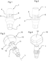
- the abutment base 1 particularly shown on the Figures 1 to 8 , comprises two main parts, separated by a collar 2.
- a first part comprises a connection device 3 with an implant.
- a second coronal part is intended to receive a healing cap 10.
- it comprises a connection device 4 with such a cap.
- this connection device 4 comprises a clipping element 5 and an anti-rotational element 6, to prevent the cap from rotating around the longitudinal axis L of the abutment base 1, this longitudinal axis L being moreover intended for alignment with the axis of a implant.
- the anti-rotational element 6 is a lug. This anti-rotational element 6 is further aligned with a particular surface of the connection device 3 with an implant.
- the clipping element 5 is formed by several grooves arranged on the circumference of the abutment base 1 in the vicinity of the collar 2.
- the clipping element 5 is such that it makes it possible to obtain an audible click when fixing by clipping a healing cap 10.
- the abutment base 1 used is non-definitive, participates in the first healing phase only, is preferably removed when finalizing the restoration and replaced by a definitive restorative abutment (which may be in the form of another base).
- a definitive restorative abutment which may be in the form of another base.
- the same abutment base 1 is optionally removed, cleaned and reused in the definitive restoration, thus fulfilling the second function of restorative abutment.
- the abutment base 1 is preferably universal, and has a symmetrical or more precisely quasi-symmetrical shape (the anti-rotational element forms for example an exception to the symmetry) around a longitudinal axis L which forms an axis of revolution.
- This axis L therefore forms in particular a central axis of symmetry of the connection device 3 with an implant.
- this same axis L also forms an axis of symmetry of the connection device 4 with a cap.
- the abutment base 1 therefore extends globally in a single direction, identified by a single longitudinal axis L.
- the abutment base comprises a longitudinal axis L which extends over its entire length, in a manner capable of alignment with the axis of an implant 60.
- the two connection devices 3, 4 of the abutment base 1 are arranged at different levels around this same longitudinal axis L.
- an abutment base 1 is fixed on the implant 60 by its connection device 3, and by means of a screw 61, then a cap 10 is fixed on the second coronal part of the abutment base.
- This assembly is illustrated by the figures 23 And 24 .
- the cap 10 comprises an opening 11 for forming a connecting part and a hollow interior volume, intended for the insertion of the second coronal part of the abutment base.
- the periphery of this opening 11 comprises a surface 12 intended to come to bear on a corresponding flat surface of the collar 2 of the abutment base, after clipping the cap 10 onto the abutment base, to reach the assembled assembly represented by the Figures 5 to 8 And 19a has 19d .
- connection devices of the existing implants there are as many different abutment bases as there are different connection devices of the existing implants, in order to be able to have, for each existing implant, an abutment base equipped with a connection device 3 adapted to it.
- the advantage of this approach is that it allows the entire second coronal part of the abutment bases, from the collar 2, to be kept unchanged, regardless of the implant corresponding to the abutment base.
- the cap 10 has the function of being housed within the incised gum, after fixing an implant, by fixing, preferably removable, on an abutment base connected to the implant.
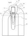
- the final configuration is shown in the figure 24 .
- the implant 60 is secured to the bone part 62
- the pillar base 1 is fixed on the implant 60, so that its collar 2 is positioned at the border between the bony part 62 and the gum 63.
- the cap 10 covers the abutment base 1 up to the collar 2, so that the gum 63 is almost exclusively in contact with the cap 10.
- the assembly formed by the assembly of a cap on a abutment base thus corresponds to a healing assembly, which temporarily participates in the restoration process, allowing healing and the smooth manufacture of the definitive prosthesis, as will be detailed later.
- the gum 63 therefore heals around the lateral surface 13 of the cap 10.
- this lateral surface 13 is chosen to correspond as closely as possible to the patient's oral environment.
- the terminal surface 14 opposite the opening 11 of the cap is intended to remain visible above the gingival surface 64 of the gum 63, or at least partially visible, since the gum remains mainly in contact with the lateral surface 13 of the cap.
- at least a part of the terminal surface 14 and possibly an upper part of the lateral surface 13 therefore form an emerging surface of the cap.
- This emerging surface is illustrated in particular by the Figures 25 and 26 .
- caps of different heights can be provided to adapt to different configurations of the oral geometry. As examples of embodiments, three different standard heights allow good adaptation to all situations. This height is advantageously between 3 and 7 mm. Due to the use of an abutment base which acts as an interface, the same cap 10 is thus universally adapted to all existing implants.
- the shape of the cap is specifically chosen to promote the healing of the gum, according to an anatomical shape corresponding as best as possible to the tooth to be replaced and consequently also to the future prosthesis intended to occupy this oral space.
- This shape is notably characterized by the flat section of its lateral surface 13, this section being a transverse section through a plane P perpendicular to the lateral surface 13, shown in the figure 23 , and substantially parallel to the terminal surface 14.
- this section is substantially reproduced by the shape of the terminal surface 14, or more precisely by the projection of this terminal surface 14 on such a perpendicular plane, that is to say substantially parallel to the gingival surface 64.
- the figure 9 illustrates a top view of the upper and lower teeth and the figure 10 illustrates a sectional view at the level of the justogingival plane PJ of a dentition, represented on the figure 24 , at the level of the root of the emergence of the teeth.
- These figures show that the teeth have sections of different shapes, which can be simplified by rectangular and/or square and/or triangular shapes, but more precisely trapezoidal.
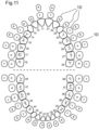
- figure 11 thus represents a top view of the sections of all the teeth and a top view of caps 10 associated with each tooth.
- the shapes of the different series of teeth numbered from 11 to 18, from 21 to 28, from 31 to 38 and from 41 to 48 in this figure, these numbers not to be confused with the numerical references used elsewhere in the other figures to designate the characteristics of the invention, are all approached by means of four different caps 10, referenced A to D. For certain teeth, or even all the teeth, several caps, among the caps A to D, appear suitable.
- a healing element which is the subject of the invention may indifferently correspond either to the assembly formed by a pillar base and by one of the caps of the series fixed on the base abutment opposite its connection to the dental implant, or to a unitary healing element directly fixed on the dental implant 60 without use of the abutment base.
- a series of healing elements will be such that the healing elements which compose it have different heights between them and/or have transverse sections of their lateral surfaces 13 or projections on a parallel plane of their emerging or terminal surfaces which are different between them.
- the transverse sections of the lateral surfaces 13 or the projections on a parallel plane of their emerging or terminal surfaces 14 are each among: a substantially trapezoidal shape or a substantially polygonal shape, or triangular, or square, or rectangular, or ovoid, or a substantially polygonal shape with rounded corners, or cylindrical.
- caps A are suitable for treating the restoration of the upper lateral incisors and all lower incisors.
- Caps B are suitable for the restoration of canines and premolars
- caps C are suitable for the restoration of intermediate molars
- caps D are suitable for the restoration of the larger molars.
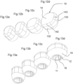
- the terminal surfaces 14 of these caps 10 (A to D), intended for positioning above the gingival emergence, are substantially flat and intended for positioning parallel to a horizontal plane (parallel to the justa-gingival plane PJ, between 1 and 2 mm inclusive above this plane) corresponding to the cutting plane of the figure 9 . They are however slightly curved, presenting a central part 145, more particularly visible on the Figures 14a to 14d , intended to rise further beyond the gum than its peripheral parts 146.
- the transverse section of the cap by a plane P perpendicular to its lateral surface 13, as explained previously, which gives the final shape to the gum after healing, is substantially reproduced by the terminal surface 14 of the cap, which comes in its extension.
- the sections of all the caps all have a substantially trapezoidal shape. They comprise a large side 141, which will be arranged on the outside of the mouth (vestibular side), a small side 142 opposite parallel, which will be arranged on the inside of the mouth (lingual side), connected by two sides 143, 144. The intersection of the diagonals of the trapezium makes it possible to define a center 15.
- the center 17 of the substantially circular opening 11 of the opposite surface of the cap 10 it is possible to define a central axis 18 of the cap, passing through the two central points 15, 17.
- This axis 18 of the cap 10 is perpendicular to the terminal surface 14.
- the entire architecture of the abutment base and an associated cap 10 is designed so that the axis 18 of the cap corresponds to the longitudinal axis L of the abutment base, and to the axis of the implant.
- the four types of caps 10, A, B, C and D therefore differ in particular by the trapezoidal shape of the cross-section of their lateral surfaces 13.
- the trapezoid of the smallest cap A is close to a triangle, because its short side 142 is very small.
- the trapezium of the cap B is close to a rectangle, the long side of which goes from the outside of the mouth to the inside, and corresponds to the sides 143, 144.
- the trapeziums of the caps C and D are close to a rectangle, or even a square, the long side of which is in the opposite direction, and corresponds to the sides 141, 142, which are of similar but slightly different lengths.
- the Figures 16a to 16d give orders of magnitude of the dimensions of these caps, in millimeters.
- the terminal surface 14 of each cap ignoring the markers arranged on this surface and which will be described later, has a continuous surface, without reliefs, and/or without a hollow part, and/or without a groove, and/or without a ridge, and/or without roughness.
- This surface is convex. In particular, it does not have a hollow shape, and naturally no through opening (through), as would be necessary if it were chosen to fix the cap by a fixing screw.
- This geometry without roughness is favorable to oral hygiene, for example preventing the accumulation of food and the deposit of dental plaque.
- the series of caps could comprise a different number of different geometries, for example at least three, or even at least two.
- a single cap shape could be suitable for all teeth.
- the cross-section of a cap at its lateral surface 13 could approach any polygon, such as a three-, five- or six-sided polygon.
- the corners of these polygons could be so rounded that the overall shape would approach an oblong shape, or even an ovoid section, or even any other shape. further from a polygon.
- this shape comprises at least one center or point perfectly defined geometrically to define a center 15, or even a possible axis 18 of the cap, this center being advantageously, but not necessarily, in alignment with the longitudinal axis L of the pillar base.
- the geometry of the visible emerging surface of the cap on the inside of the mouth differs from the geometry on the outside, to take into account the curvature of the gum.
- This shape of the emerging surface of the cap is therefore asymmetrical with respect to a median plane containing the tangent T of the gum and passing through the center of the cap, called the median tangent plane; this tangent T (and therefore the projection of the median tangent plane) is shown on the Figures 15a to 15d and more precisely on the figure 9 considering a tooth 50 to be restored.
- This median plane, called tangent plane T is parallel to the tangent T to the gum, perpendicular to the justogingival plane PJ, passes through the middle 15 of a cap.
- a circular section shape for the cap section is unsuitable. More generally, any planar section exhibiting symmetry around a point or an axis is poorly or not at all suitable for the aforementioned cap section, because it would not be adapted to the anatomy of the mouth.
- the emerging and visible surface of the cap, in particular the terminal surface 14 is therefore generally not symmetrical with respect to at least one, or even several planes comprising its axis 18. It is not symmetrical with respect to at least one, or several planes perpendicular to the terminal surface 14 and passing through its center 15.
- a perpendicular median plane a plane corresponding to a definition given above.
- Such a plane is substantially perpendicular to the terminal surface 14 of the healing element, and therefore also substantially perpendicular to the justogingival plane forming the final surface of the gingiva, from which the teeth emerge. It passes through the center of the terminal surface 14.
- a perpendicular median plane can be defined as any plane containing the axis 18 of the cap. In the example shown, particularly visible on the Figures 15a to 15d , only the median plane perpendicular to the tangent plane T mentioned, passing through the middle of the two sides 141, 142, forms a plane of symmetry.
- the end surfaces 14 of the caps are extended from their periphery 146 by the lateral surface 13 around which the gum mainly heals, and which thus gives the gum shape adapted to the future prosthesis.
- This lateral surface 13 has several surfaces 131, 132, 133, 134, substantially flat, possibly slightly curved, extending in a direction substantially parallel to the axis 18 of the cap and/or parallel to the longitudinal axis L of the abutment base, respectively extending the different sides 141, 142, 143, 144 of the end surface 14 of the cap.
- the interfaces between the end surface 14 and these different parts of the lateral surface 13 are produced by rounded surfaces, without asperity, in particular convex.
- the lateral surface 13 of the caps ends with a substantially truncated surface 19, up to the substantially circular opening 11, mentioned above.
- This opening 11 opens onto a hollow part internal to the cap 10, which allows the housing of the second coronal part of the pillar base.
- This hollow part is provided with a fixing device complementary to that 4 of the pillar base. In the embodiment, these are beads provided to clip onto the grooves 5 of the pillar base.
- a substantially longitudinal groove 16 is arranged in this hollow part of the cap, to cooperate with the lug, thus forming a connection blocked in rotation, and perfectly indexed, the orientation of the cap being unique and perfectly imposed.
- Figures 3 to 8 And 17a has 17d, 18a to 18d And 19a to 19d , particularly show a healing assembly according to the invention, formed by the assembly of a cap 10 with a pillar base 1.
- the cap may be formed of a plastic material, compatible with medical use, and of a pink, white or cream color. Alternatively, it may be made of metal, for example titanium, or may be zirconia.
- the use of healing caps therefore makes it possible to promote ideal healing of the gum in a dental restoration process, as discussed, due to its geometry designed in line with oral anatomy.
- the solution has been described with a removable healing cap separate from a base in the previous embodiment.
- this healing element may alternatively be completely subgingival and invisible, then made visible by intervention on the gum to implement the remainder of the recognition process which is described below. In this case, the end portion of the cap will always be incorrectly called the emerging portion.
- the cap 10 will also be more generally called a "healing element" 10 hereinafter.
- the emerging surface formed by the end surface 14 and possibly the upper part of the lateral surface 13, advantageously comprises at least two informative markers allowing the identification of at least two characteristics of the healing cap 10 and/or indirectly of the abutment base 1 and/or of the dental implant 60.
- the arrangement of such informative markers on the healing cap 10 makes it possible to avoid having to resort to a traditional impression-taking technique on the implant and to reduce the time required and the complexity for subsequently developing the dental restoration abutment which will be placed in place to replace the healing cap 10 and the abutment base 1, and on which the final prosthesis will be arranged.
- said at least two informative markers comprise a first type of informative marking of a first characteristic of the healing cap 10 and a second type of informative marking of a second characteristic of the healing cap 10.
- first and second characteristics linked to the healing cap 10 are in particular the height of the healing element 10 and/or the shape of the healing cap 10, in particular the shape and dimensions of the transverse section of its lateral surface 13 or of the projection on a parallel plane of the emerging surface.
- a marker can make it possible to deduce information on the abutment base and possibly on the implant, such as their orientation, which can be linked to the orientation of the cap.
- the characterization of the negative informative marker which is for example a simple hole, is for example its position relative to the rest of the cap 10 in which it is formed, its size, its shape or the number of such negative informative markers.
- These characteristics of each negative informative marker make it possible to characterize the characteristic of the healing cap 10 and/or of the pillar base 1 characterized by the negative informative marker(s), such as for example the height of the healing element. For example, the height position of the pillar base 1 can then be deduced therefrom.
- these same characteristics can be deduced from the characterization of the positive informative marker, which is for example its position relative to the rest of the cap 10 in which it is formed, its size, its shape or the number of such positive informative markers.
- These characteristics of each positive informative marker make it possible precisely to characterize the characteristic of the healing cap 10 and/or of the abutment base 1 and therefore of the dental implant 60 characterized by the positive informative marker(s).
- Another example of such informative markers of particular and identifiable shapes is a notch formed directly in the healing cap 10 itself.
- the joint presence of two such notches and the distance separating them can serve to indicate for example the position and the type of abutment base and by relation the dental implant 60.
- a third example of such informative markers of particular and identifiable shapes is a line, such as an engraving or a relief, integral with the healing cap 10. The dimension, the position of this line and/or the number of such lines can serve to characterize an additional characteristic of the healing cap 10 and/or of the abutment base 1 and therefore of the dental implant 60.
- a practitioner can take a digital impression of the patient's mouth, without removing the healing element (the cap).
- the digital data obtained by any device such as a mouth scanner for example, are automatically transmitted to a computer equipped with dental restoration software.
- This software has a human-machine interface, through which an operator can indicate the model of cap he used, or more generally the reference of the healing element, and possibly of the implant and/or the abutment base used.
- the informative markers can be indicated to the software by the operator himself or identified automatically by the software by any means of detection, recognition and identification adapted according to the nature of the marker and its characterization.
- the healing element From the scanning data and the informative markers, software automatically determines the axis of the healing element, by geometric construction, for example from the identification of the center 15 of the cap and the direction perpendicular to the terminal surface 14 passing through this center 15, then its orientation and the space it occupies, using the markers. It can thus in particular automatically determine the axis of the implant, without having to visualize it directly. Indeed, the healing element is advantageously aligned with the implant, its axis thus being merged with that of the implant.
- connection device 3 of the abutment base with the implant it is possible to deduce from the informative markers the orientation of the axis of the connection device with the implant, for example the connection device 3 of the abutment base with the implant: this makes it possible to automatically deduce the positioning of the connection device of the implant, without having to visualize it directly, from the knowledge of the abutment base.
- a first approach may consist in forming healing elements of different colors for different heights.
- a second approach consists in providing and identifying at least one informative marker on the healing element to indicate this height.
- an operator enters the reference of the healing element via a human-machine interface, which allows the software to find certain characteristics of this healing element, in confirmation or in addition to those obtained by the markers, such as its height, its center and/or axis, in a library present in the form of a database stored in a memory. electronic that he can consult.
- the figure 20 illustrates as an example a virtual cap 10' stored in the library associated with the restoration software.
- a reference in space 51' is associated with the cap, allowing its positioning in space.
- the software can automatically recognize the healing element from its informative markers, or even from its other geometric characteristics, without manual entry of its reference.
- An operator can assist a software in the correct positioning of the reference 51 of the real cap, that is to say in the recognition of its real positioning, by entering on an image obtained by the digitization step mentioned above and presented to the operator on a screen of a human-machine interface one or more points of the emerging surface.
- the software can therefore associate the virtual healing element from its library with the digitized oral environment, replacing the real healing element, to obtain a more perfect digital reproduction.
- the actual reference mark 51 of the actual cap 10 is thus automatically determined by the software. It is possible to perfectly position the virtual healing element on the digital impression, automatically or possibly via an operator intervention on a human-machine interface allowing the oral impression and the healing element to be viewed.
- This perfect positioning of the virtual healing element makes it possible to deduce all the neighboring geometries, from the known references stored in the database associated with the precise healing element considered, including the position of the implant 60 and the geometry of the healed gum without the presence of the cap 10 or the abutment base, as represented by the figure 22 .
- the markers used are sufficient to provide the data necessary for the correct positioning of the cap without resorting to a library.
- the restoration software when the restoration software has accurately repositioned the positioning of the hidden implant, it deduces from this knowledge the final geometry of the restoration abutment to be manufactured, which must be fixed to the implant and occupy the entire gingival volume defined by the healing element, then the geometry of the dental prosthesis intended to be fixed on this abutment, in a known manner.
- this restoration process can be done completely digitally, therefore virtually, in a totally or partially automated manner, or include phases of construction of a plastic or plaster model.
- a physical impression for example in silicone, can be made, a plaster can be poured into the impression to create the master model, that is to say a replica of the dental arch to be restored, which is then scanned in the laboratory to reconstruct a digital image.
- a restoration device which comprises a central processing and control unit, here comprising at least one microprocessor, linked to an electronic memory, on which software is executed allowing the implementation of all or part of the steps of the restoration method described above.
- This central unit is linked by a communication device to a module for obtaining digital data representing all or part of a patient's dentition, which may consist of a device such as a mouth scanner. It is also linked to a human-machine interface, comprising for example a screen and/or a keyboard, to allow exchanges with an operator, as explained above.
- the central unit then performs all the necessary processing, calculations and others, by software means. It is finally able to generate and transmit manufacturing commands to a device for manufacturing a restoration and/or prosthesis abutment. It can also be linked by a second communication device to a manufacturing device such as a machine tool.
- the healing element may be unitary, suitable for direct attachment to a dental implant 60 without the use of an abutment base.
- Said at least two informative markers 70 may comprise a first type of informative marking of a first characteristic of the healing element 10 and a second type of informative marking of a second distinct characteristic of the healing element 10.
- the invention also relates to a series of healing elements, characterized in that it comprises at least two healing elements as described above having different shapes, or in that it comprises at least three healing elements as described above having different shapes.
- Said at least two or at least three healing elements may have different heights between them and/or have cross sections of their lateral surfaces 13 or projections on a parallel plane of their terminal surfaces 14 which are different between them.
- the method may comprise a step of automatically determining the axis of the healing element, from the identification of the center 15 of the healing element and the direction perpendicular to the terminal surface 14 passing through this center 15, a step of automatically determining the axis of the implant, merged with the axis of the healing element, and a step of determining the orientation of the healing element from the markers.
- the method may comprise a step of determining the height of the healing element, from healing elements of different colors for different heights or by identifying at least one informative marker which indicates this height on the healing element.
- the method may comprise a step of entering the reference of the healing element by a human-machine interface, then a step consisting of finding characteristics of this healing element, in confirmation or in addition to those obtained by the markers, among its height, its center and/or axis, in a library present in the form of a database stored in an electronic memory.
- the method may comprise a step of capturing one or more points of the emerging surface by a human-machine interface on an image obtained by the step of producing a digital impression of the oral space.
- the method may comprise a step of deducing the final geometry of the restoration abutment to be manufactured, which must be fixed to the dental implant so as to occupy the entire gingival volume defined by the healing element, and of determining the geometry of the dental prosthesis intended to be fixed on this restoration abutment.
Landscapes
- Health & Medical Sciences (AREA)
- Animal Behavior & Ethology (AREA)
- Veterinary Medicine (AREA)
- Life Sciences & Earth Sciences (AREA)
- Oral & Maxillofacial Surgery (AREA)
- General Health & Medical Sciences (AREA)
- Epidemiology (AREA)
- Public Health (AREA)
- Dentistry (AREA)
- Orthopedic Medicine & Surgery (AREA)
- Dermatology (AREA)
- Transplantation (AREA)
- Chemical & Material Sciences (AREA)
- Medicinal Chemistry (AREA)
- Dental Prosthetics (AREA)
- Dental Preparations (AREA)
- Prostheses (AREA)
Applications Claiming Priority (4)
| Application Number | Priority Date | Filing Date | Title |
|---|---|---|---|
| FR1560235A FR3042699B1 (fr) | 2015-10-27 | 2015-10-27 | Element de cicatrisation pour une restauration dentaire |
| EP22192558.9A EP4119090B1 (de) | 2015-10-27 | 2016-10-24 | Heilendes element für eine zahntechnische restauration |
| EP16788060.8A EP3367961B1 (de) | 2015-10-27 | 2016-10-24 | Vernarbungselement für restaurative zahnmedizin |
| PCT/EP2016/075507 WO2017072066A1 (fr) | 2015-10-27 | 2016-10-24 | Element de cicatrisation pour une restauration dentaire |
Related Parent Applications (2)
| Application Number | Title | Priority Date | Filing Date |
|---|---|---|---|
| EP16788060.8A Division EP3367961B1 (de) | 2015-10-27 | 2016-10-24 | Vernarbungselement für restaurative zahnmedizin |
| EP22192558.9A Division EP4119090B1 (de) | 2015-10-27 | 2016-10-24 | Heilendes element für eine zahntechnische restauration |
Publications (2)
| Publication Number | Publication Date |
|---|---|
| EP4501274A2 true EP4501274A2 (de) | 2025-02-05 |
| EP4501274A3 EP4501274A3 (de) | 2025-04-09 |
Family
ID=56555411
Family Applications (3)
| Application Number | Title | Priority Date | Filing Date |
|---|---|---|---|
| EP24220977.3A Pending EP4501274A3 (de) | 2015-10-27 | 2016-10-24 | Heilungselement für eine zahnrestauration |
| EP16788060.8A Active EP3367961B1 (de) | 2015-10-27 | 2016-10-24 | Vernarbungselement für restaurative zahnmedizin |
| EP22192558.9A Active EP4119090B1 (de) | 2015-10-27 | 2016-10-24 | Heilendes element für eine zahntechnische restauration |
Family Applications After (2)
| Application Number | Title | Priority Date | Filing Date |
|---|---|---|---|
| EP16788060.8A Active EP3367961B1 (de) | 2015-10-27 | 2016-10-24 | Vernarbungselement für restaurative zahnmedizin |
| EP22192558.9A Active EP4119090B1 (de) | 2015-10-27 | 2016-10-24 | Heilendes element für eine zahntechnische restauration |
Country Status (10)
| Country | Link |
|---|---|
| US (1) | US20180325630A1 (de) |
| EP (3) | EP4501274A3 (de) |
| KR (1) | KR102768867B1 (de) |
| CN (1) | CN108366845A (de) |
| BR (1) | BR112018008691B1 (de) |
| ES (2) | ES3014442T3 (de) |
| FR (1) | FR3042699B1 (de) |
| IL (1) | IL258961B2 (de) |
| MA (2) | MA58979B1 (de) |
| WO (1) | WO2017072066A1 (de) |
Families Citing this family (17)
| Publication number | Priority date | Publication date | Assignee | Title |
|---|---|---|---|---|
| WO2015189647A1 (en) | 2014-06-13 | 2015-12-17 | Vergoullis Loannis | Molds for custom dental implant abutments and impression posts |
| EP3231391B1 (de) | 2016-04-14 | 2018-12-26 | Neoss Limited | Schraubendreher und schraube für medizinische anwendungen, insbesondere für zahnärztliche anwendungen |
| EP3528740B1 (de) | 2016-12-16 | 2022-12-07 | Neoss Limited | Dentaler abutmentrohling und verfahren zur herstellung einer zahnprothese aus solch einem rohling |
| FR3067587B1 (fr) | 2017-07-07 | 2021-06-25 | Euroteknika | Ensemble de prise d'empreinte dentaire |
| GB201712780D0 (en) * | 2017-08-09 | 2017-09-20 | Neoss Ltd | Dental implant assembly |
| GR20170100383A (el) | 2017-08-21 | 2019-04-22 | Vp Innovato Holdings Ltd | Πυρηνας οδοντικου κολοβωματος και μεθοδος για την κατασκευη ενος οδοντικου κολοβωματος |
| DE102018102568A1 (de) * | 2018-02-06 | 2019-08-08 | Karl Leibinger Medizintechnik Gmbh & Co. Kg | Implantat mit radial erweitertem Pfosten an Trägerstruktur, Weichgewebeverdrängungssystem, Fertigungsverfahren und Planungsverfahren zum Fertigen eines Implantats |
| GR1009730B (el) * | 2018-08-31 | 2020-05-15 | Vp Innovato Holdings Ltd | Αξονες ψηφιακης αποτυπωσης με σαρωση και μεθοδολογια |
| US11737858B2 (en) * | 2018-11-14 | 2023-08-29 | Terry B. Philibin | Healing abutment system for configuring crown abutments at an implant site |
| USD982375S1 (en) | 2019-06-06 | 2023-04-04 | Sharkninja Operating Llc | Food preparation device |
| WO2021067736A1 (en) * | 2019-10-02 | 2021-04-08 | Full Arch World Wide, Llc | Tissue former for dental implants |
| FR3102354B1 (fr) * | 2019-10-23 | 2022-10-21 | Creadent Montauban | Pilier de cicatrisation de la gencive autour d’un implant pour la pose d’une dent prothétique. |
| LU101581B1 (fr) * | 2019-12-24 | 2021-06-28 | Baptista Augusto Andre | Pilier de cicatrisation anatomique implantaire provisoire |
| GR20200100312A (el) | 2020-06-04 | 2022-01-13 | Ιωαννης Αντωνιου Βεργουλλης | Συστημα αξονων σαρωσης και μεθοδος |
| KR102242487B1 (ko) * | 2021-01-22 | 2021-04-19 | 김정규 | 밴드타입 크라운 |
| CN113888460A (zh) * | 2021-07-14 | 2022-01-04 | 深圳市菲森科技有限公司 | 口内扫描中特征匹配种植体的方法及相关设备 |
| US20250262032A1 (en) * | 2024-02-16 | 2025-08-21 | Dan Rosen | Dental implant screw with variable profile head |
Family Cites Families (17)
| Publication number | Priority date | Publication date | Assignee | Title |
|---|---|---|---|---|
| KR19990082264A (ko) | 1996-02-02 | 1999-11-25 | 키이스 디 | 치료 접합부와 의치본 코핑이 조합된 융기 프로파일 시스템 |
| US5759036A (en) * | 1996-07-29 | 1998-06-02 | Hinds; Kenneth F. | Complete dental implant system and method |
| JP3414757B2 (ja) * | 1997-05-24 | 2003-06-09 | シュトラウマン・ホールデイング・アー・ゲー | 義歯を形成するための装置 |
| US6790040B2 (en) | 1999-11-10 | 2004-09-14 | Implant Innovations, Inc. | Healing components for use in taking impressions and methods for making the same |
| IT1317364B1 (it) * | 2000-09-12 | 2003-06-16 | Vincenzo Crudo | Impianto perfezionato per il fissaggio di protesi dentarie. |
| JP5021660B2 (ja) * | 2005-10-24 | 2012-09-12 | バイオメット・3アイ・エルエルシー | 歯科用インプラント構成要素を製造するための方法 |
| US20090155744A1 (en) * | 2007-12-13 | 2009-06-18 | Global Implant Solutions, Llc | Dental Implant Identification System |
| DE202009004008U1 (de) * | 2009-03-25 | 2010-08-12 | Kühnel, Wolfgang, Dr. | Gingivaformer |
| EP3388022B1 (de) * | 2011-02-23 | 2020-01-29 | 3Shape A/S | Verfahren zur modifizierung des gingivateils eines virtuellen modells eines gebisses |
| KR101108280B1 (ko) * | 2011-04-20 | 2012-01-31 | 김용상 | 임플란트 |
| US20130196290A1 (en) * | 2011-05-16 | 2013-08-01 | Biomet 3I, Llc | Healing Abutment Assembly With Combination Of Scanning Features |
| US11020204B2 (en) * | 2011-12-21 | 2021-06-01 | 3Shape A/S | Virtually designing a customized healing abutment |
| KR101375154B1 (ko) * | 2012-07-16 | 2014-04-21 | 라파바이오 주식회사 | 치아 형상에 대응하는 힐링 어버트먼트 |
| KR20140120032A (ko) * | 2013-04-02 | 2014-10-13 | (주) 코웰메디 | 스프링 결합식 임플란트 지대체 시스템 |
| KR101419519B1 (ko) * | 2013-10-10 | 2014-08-13 | (주)교보테크 | 임플란트 어셈블리 |
| KR101535294B1 (ko) * | 2014-05-14 | 2015-07-10 | 최종훈 | 디지털 힐링 어버트먼트 |
| CN203873904U (zh) * | 2014-06-04 | 2014-10-15 | 重庆润泽医药有限公司 | 一种嵌合式种植牙 |
-
2015
- 2015-10-27 FR FR1560235A patent/FR3042699B1/fr active Active
-
2016
- 2016-10-24 MA MA58979A patent/MA58979B1/fr unknown
- 2016-10-24 KR KR1020187014342A patent/KR102768867B1/ko active Active
- 2016-10-24 ES ES22192558T patent/ES3014442T3/es active Active
- 2016-10-24 US US15/770,962 patent/US20180325630A1/en not_active Abandoned
- 2016-10-24 EP EP24220977.3A patent/EP4501274A3/de active Pending
- 2016-10-24 ES ES16788060T patent/ES2929618T3/es active Active
- 2016-10-24 WO PCT/EP2016/075507 patent/WO2017072066A1/fr not_active Ceased
- 2016-10-24 CN CN201680071870.5A patent/CN108366845A/zh active Pending
- 2016-10-24 EP EP16788060.8A patent/EP3367961B1/de active Active
- 2016-10-24 MA MA43105A patent/MA43105B1/fr unknown
- 2016-10-24 EP EP22192558.9A patent/EP4119090B1/de active Active
- 2016-10-24 BR BR112018008691-6A patent/BR112018008691B1/pt active IP Right Grant
-
2018
- 2018-04-26 IL IL258961A patent/IL258961B2/en unknown
Also Published As
| Publication number | Publication date |
|---|---|
| CN108366845A (zh) | 2018-08-03 |
| FR3042699A1 (fr) | 2017-04-28 |
| IL258961A (en) | 2018-06-28 |
| MA43105A (fr) | 2021-03-17 |
| EP3367961A1 (de) | 2018-09-05 |
| WO2017072066A1 (fr) | 2017-05-04 |
| MA58979B1 (fr) | 2025-04-30 |
| EP4501274A3 (de) | 2025-04-09 |
| ES3014442T3 (en) | 2025-04-22 |
| BR112018008691B1 (pt) | 2021-03-02 |
| EP4119090A1 (de) | 2023-01-18 |
| IL258961B1 (en) | 2023-01-01 |
| BR112018008691A2 (pt) | 2018-10-30 |
| KR20180071343A (ko) | 2018-06-27 |
| IL258961B2 (en) | 2023-05-01 |
| FR3042699B1 (fr) | 2021-02-19 |
| ES2929618T3 (es) | 2022-11-30 |
| EP4119090C0 (de) | 2024-12-25 |
| EP3367961B1 (de) | 2022-08-31 |
| KR102768867B1 (ko) | 2025-02-14 |
| US20180325630A1 (en) | 2018-11-15 |
| EP4119090B1 (de) | 2024-12-25 |
| MA43105B1 (fr) | 2023-01-31 |
Similar Documents
| Publication | Publication Date | Title |
|---|---|---|
| EP4119090B1 (de) | Heilendes element für eine zahntechnische restauration | |
| EP3212118B1 (de) | Wundheilende einheit für einen zahnersatz | |
| FR3057457A1 (fr) | Pilier de cicatrisation pour une restauration dentaire | |
| EP3445270B1 (de) | System zur herstellung einer orthodontischen vorrichtung | |
| EP3641692B1 (de) | Anordnung zur zahnrestauration | |
| EP3600134B1 (de) | Einheilkappe, zahnrestaurationsverfahren und verfahren zur herstellung eines pfeilers für eine zahnrestauration | |
| EP4161434B1 (de) | Verfahren zur verfolgung einer zahnbewegung | |
| EP3641693B1 (de) | Zahnwundheilelement | |
| WO2018234247A1 (fr) | Ensemble de restauration dentaire | |
| EP3648700B1 (de) | Satz zum zahnabformen | |
| FR3074030B1 (fr) | Procede de fabrication d'un ensemble de restauration dentaire | |
| EP3849462B1 (de) | Einstückiges zahnärztliches wundheilelement | |
| EP3629994B1 (de) | Kieferorthopädische vorrichtung und verfahren zur herstellung einer solchen vorrichtung | |
| FR3046050A1 (fr) | Prothese dentaire | |
| FR3154595A1 (fr) | Tenon radiculaire dentaire d’empreinte optique et procédés s’y rapportant | |
| FR3047165A1 (fr) | Dispositif de parure dentaire amovible |
Legal Events
| Date | Code | Title | Description |
|---|---|---|---|
| PUAI | Public reference made under article 153(3) epc to a published international application that has entered the european phase |
Free format text: ORIGINAL CODE: 0009012 |
|
| STAA | Information on the status of an ep patent application or granted ep patent |
Free format text: STATUS: THE APPLICATION HAS BEEN PUBLISHED |
|
| AC | Divisional application: reference to earlier application |
Ref document number: 3367961 Country of ref document: EP Kind code of ref document: P Ref document number: 4119090 Country of ref document: EP Kind code of ref document: P |
|
| AK | Designated contracting states |
Kind code of ref document: A2 Designated state(s): AL AT BE BG CH CY CZ DE DK EE ES FI FR GB GR HR HU IE IS IT LI LT LU LV MC MK MT NL NO PL PT RO RS SE SI SK SM TR |
|
| REG | Reference to a national code |
Ref country code: DE Ref legal event code: R079 Free format text: PREVIOUS MAIN CLASS: A61C0009000000 Ipc: A61C0008000000 |
|
| PUAL | Search report despatched |
Free format text: ORIGINAL CODE: 0009013 |
|
| AK | Designated contracting states |
Kind code of ref document: A3 Designated state(s): AL AT BE BG CH CY CZ DE DK EE ES FI FR GB GR HR HU IE IS IT LI LT LU LV MC MK MT NL NO PL PT RO RS SE SI SK SM TR |
|
| RIC1 | Information provided on ipc code assigned before grant |
Ipc: A61C 9/00 20060101ALI20250303BHEP Ipc: A61C 8/00 20060101AFI20250303BHEP |
|
| STAA | Information on the status of an ep patent application or granted ep patent |
Free format text: STATUS: REQUEST FOR EXAMINATION WAS MADE |
|
| 17P | Request for examination filed |
Effective date: 20251007 |