EP4501257A2 - Vorrichtung zur gewebeentfernung - Google Patents
Vorrichtung zur gewebeentfernung Download PDFInfo
- Publication number
- EP4501257A2 EP4501257A2 EP24218339.0A EP24218339A EP4501257A2 EP 4501257 A2 EP4501257 A2 EP 4501257A2 EP 24218339 A EP24218339 A EP 24218339A EP 4501257 A2 EP4501257 A2 EP 4501257A2
- Authority
- EP
- European Patent Office
- Prior art keywords
- housing
- cutting tool
- probe device
- cover
- probe
- Prior art date
- Legal status (The legal status is an assumption and is not a legal conclusion. Google has not performed a legal analysis and makes no representation as to the accuracy of the status listed.)
- Pending
Links
Images


Classifications
-
- A—HUMAN NECESSITIES
- A61—MEDICAL OR VETERINARY SCIENCE; HYGIENE
- A61F—FILTERS IMPLANTABLE INTO BLOOD VESSELS; PROSTHESES; DEVICES PROVIDING PATENCY TO, OR PREVENTING COLLAPSING OF, TUBULAR STRUCTURES OF THE BODY, e.g. STENTS; ORTHOPAEDIC, NURSING OR CONTRACEPTIVE DEVICES; FOMENTATION; TREATMENT OR PROTECTION OF EYES OR EARS; BANDAGES, DRESSINGS OR ABSORBENT PADS; FIRST-AID KITS
- A61F9/00—Methods or devices for treatment of the eyes; Devices for putting in contact-lenses; Devices to correct squinting; Apparatus to guide the blind; Protective devices for the eyes, carried on the body or in the hand
- A61F9/007—Methods or devices for eye surgery
-
- A—HUMAN NECESSITIES
- A61—MEDICAL OR VETERINARY SCIENCE; HYGIENE
- A61B—DIAGNOSIS; SURGERY; IDENTIFICATION
- A61B17/00—Surgical instruments, devices or methods
- A61B17/32—Surgical cutting instruments
- A61B17/320016—Endoscopic cutting instruments, e.g. arthroscopes, resectoscopes
- A61B17/32002—Endoscopic cutting instruments, e.g. arthroscopes, resectoscopes with continuously rotating, oscillating or reciprocating cutting instruments
-
- A—HUMAN NECESSITIES
- A61—MEDICAL OR VETERINARY SCIENCE; HYGIENE
- A61B—DIAGNOSIS; SURGERY; IDENTIFICATION
- A61B17/00—Surgical instruments, devices or methods
- A61B17/00234—Surgical instruments, devices or methods for minimally invasive surgery
-
- A—HUMAN NECESSITIES
- A61—MEDICAL OR VETERINARY SCIENCE; HYGIENE
- A61F—FILTERS IMPLANTABLE INTO BLOOD VESSELS; PROSTHESES; DEVICES PROVIDING PATENCY TO, OR PREVENTING COLLAPSING OF, TUBULAR STRUCTURES OF THE BODY, e.g. STENTS; ORTHOPAEDIC, NURSING OR CONTRACEPTIVE DEVICES; FOMENTATION; TREATMENT OR PROTECTION OF EYES OR EARS; BANDAGES, DRESSINGS OR ABSORBENT PADS; FIRST-AID KITS
- A61F9/00—Methods or devices for treatment of the eyes; Devices for putting in contact-lenses; Devices to correct squinting; Apparatus to guide the blind; Protective devices for the eyes, carried on the body or in the hand
- A61F9/007—Methods or devices for eye surgery
- A61F9/00736—Instruments for removal of intra-ocular material or intra-ocular injection, e.g. cataract instruments
- A61F9/00763—Instruments for removal of intra-ocular material or intra-ocular injection, e.g. cataract instruments with rotating or reciprocating cutting elements, e.g. concentric cutting needles
-
- A—HUMAN NECESSITIES
- A61—MEDICAL OR VETERINARY SCIENCE; HYGIENE
- A61F—FILTERS IMPLANTABLE INTO BLOOD VESSELS; PROSTHESES; DEVICES PROVIDING PATENCY TO, OR PREVENTING COLLAPSING OF, TUBULAR STRUCTURES OF THE BODY, e.g. STENTS; ORTHOPAEDIC, NURSING OR CONTRACEPTIVE DEVICES; FOMENTATION; TREATMENT OR PROTECTION OF EYES OR EARS; BANDAGES, DRESSINGS OR ABSORBENT PADS; FIRST-AID KITS
- A61F9/00—Methods or devices for treatment of the eyes; Devices for putting in contact-lenses; Devices to correct squinting; Apparatus to guide the blind; Protective devices for the eyes, carried on the body or in the hand
- A61F9/007—Methods or devices for eye surgery
- A61F9/00781—Apparatus for modifying intraocular pressure, e.g. for glaucoma treatment
-
- A—HUMAN NECESSITIES
- A61—MEDICAL OR VETERINARY SCIENCE; HYGIENE
- A61M—DEVICES FOR INTRODUCING MEDIA INTO, OR ONTO, THE BODY; DEVICES FOR TRANSDUCING BODY MEDIA OR FOR TAKING MEDIA FROM THE BODY; DEVICES FOR PRODUCING OR ENDING SLEEP OR STUPOR
- A61M5/00—Devices for bringing media into the body in a subcutaneous, intra-vascular or intramuscular way; Accessories therefor, e.g. filling or cleaning devices, arm-rests
- A61M5/178—Syringes
- A61M5/31—Details
- A61M5/32—Needles; Details of needles pertaining to their connection with syringe or hub; Accessories for bringing the needle into, or holding the needle on, the body; Devices for protection of needles
- A61M5/3205—Apparatus for removing or disposing of used needles or syringes, e.g. containers; Means for protection against accidental injuries from used needles
- A61M5/321—Means for protection against accidental injuries by used needles
- A61M5/3243—Means for protection against accidental injuries by used needles being axially-extensible, e.g. protective sleeves coaxially slidable on the syringe barrel
- A61M5/3275—Means for protection against accidental injuries by used needles being axially-extensible, e.g. protective sleeves coaxially slidable on the syringe barrel being connected to the needle hub or syringe by radially deflectable members, e.g. longitudinal slats, cords or bands
-
- A—HUMAN NECESSITIES
- A61—MEDICAL OR VETERINARY SCIENCE; HYGIENE
- A61B—DIAGNOSIS; SURGERY; IDENTIFICATION
- A61B17/00—Surgical instruments, devices or methods
- A61B2017/00017—Electrical control of surgical instruments
- A61B2017/00132—Setting operation time of a device
-
- A—HUMAN NECESSITIES
- A61—MEDICAL OR VETERINARY SCIENCE; HYGIENE
- A61B—DIAGNOSIS; SURGERY; IDENTIFICATION
- A61B17/00—Surgical instruments, devices or methods
- A61B17/00234—Surgical instruments, devices or methods for minimally invasive surgery
- A61B2017/00353—Surgical instruments, devices or methods for minimally invasive surgery one mechanical instrument performing multiple functions, e.g. cutting and grasping
Definitions
- the present disclosure is in the field of medical devices, and relates in particular to surgical tools.
- Tissue removal from the body is solicited in various scenarios including for diagnosis or treatment purposes.
- biopsy procedure a sufficiently small tissue specimen is acquired in order to undergo examination outside the body.
- the shape of the specimen or the cavity left at the site of the removed tissue have low importance, the body heals from the injury leaving apparently no traces.
- cancer treatment may involve tissue removal.
- On-line examination is carried to ensure that the ill tissue has been removed.
- tissue is removed in order to create paths for drainage of excessive liquids such as in Glaucoma condition. In the latter case, full control over the shape and volume of the cavity inside the body is necessary.
- WO2013186779 and WO2015145444 both assigned to the assignee of the present invention, various embodiments of cutting tools for controllable creation of a channel in the eye wall are described.
- the cutting tools are directly mounted on a reusable grip unit which includes a rotor to cause rotation of the cutting tool about its longitudinal axis upon actuation of the rotor.
- US20020120285 discloses a surgical blade for use with a surgical tool for making incisions in the sclera of an eye to form a scleral pocket to receive a scleral prosthesis.
- the surgical blade comprises a rotatable support arm capable of being rotated by the surgical tool and a detachable curved cutting blade for making incisions in the sclera of an eye.
- the surgical tool causes the curved cutting blade to advance through the sclera to form an incision having dimensions to receive a scleral prosthesis.
- the incision is complete the curved cutting blade is detached from the rotatable support arm.
- the curved cutting blade is then removed from the incision by pulling the curved cutting blade forward out of the incision.
- the incision has the exact dimensions to receive a scleral prosthesis.
- the present invention provides a novel full-fledged apparatus for use in controlled tissue removal procedures.
- the apparatus of the invention is especially useful to use in treating sensitive body organs, such as the eye where accuracy of surgery is a must.
- the apparatus can then be used to create a diameter-controlled channel in the eye wall to treat glaucoma.
- the apparatus is user-friendly for both the treating and treated persons. It is safe to use and includes carefully-considered safety measures. Additionally, it assures sterile conditions while keeping the costs reasonable.
- the apparatus includes a hand-held disposable probe device which includes a cutting tool, and a separate rotating motor device (a rotor) mounted on the proximal end of the disposable probe.
- the user grasps the disposable hand-held probe, functioning as a grip unit as well as the cutting tool.
- the probe can be disposable, a one-use only device therefore sterile, made from cost-effective yet durable materials.
- the rotor can be a multi-use device made from durable materials for long-lasting operation.
- both the volume and weight of each of the hand-held probe and the rotor are under control to thereby control the overall weight of the device, a crucial factor when it comes to carrying the device by hand in order to perform sensitive and accurate surgical procedures.
- the motor is the heavier part, then making it smaller/shorter, by including the necessary transmission assembly within the lighter and disposable probe, keeps the parasite moment forces acting on the whole apparatus (the probe and the motor) balanced, and helps the physician in operating the apparatus by minimizing fatigue.
- the lighter disposable probe is longer, the motor rests between the thumb and index fingers, hence increasing the convenience and manageability of the apparatus, whether being used by a right or left hand user.
- connection of the disposable probe to the rotor can be reversible (two opposite orientations), or is possible in a plurality of pivotal orientations between them. This saves effort and time when attaching the rotor to the disposable part, while insures full functionality.
- the hand-held probe can be optimized for interaction with the external anatomy (the treated surface) of the body organ, e.g. the eye; its construction has at the top (distal) end a sufficiently short head portion with a preferred inclination angle, relative to the longer handle used to hold the probe. This enables approaching every point in the body organ comfortably from outside.
- the short head is achieved by positioning the rotor at the back (proximal) end of the hand-held device and providing a suitable transmission assembly from the rotor, through the longitudinal handle, to the cutting tool at the top end.
- the apparatus includes a plurality of user-friendly features to maximize its efficiency and ergonomics.
- the hand-held probe can be used with right and left hands alike.
- the apparatus includes a backrest for the index finger to enable better grip and control of the cutting tool's orientation.
- the positioning of the rotor at the back end of the elongated handle, such that the back end of the handle or the rotor or the interface there between sits between the surgeon's thumb and index finger (on the first dorsal interosseous muscle) functions as a balancing feature (because of the relatively heavier weight of the rotor) and consequently gives the surgeon more accurate control on the three dimensional orientation of the device.
- the transmission assembly which passes through the hand-held probe from the rotor to the cutting tool is made from disposable plastic or other low cost and durable material(s).
- the transmission assembly includes at least two consecutively arranged/coupled parts with at least an inlet part and an outlet part.
- the outlet part is installed within the hand-held probe's housing in such a way that an axial lash is maintained.
- the transmission assembly is constructed such that it pushes the cutting tool towards outside the device, i.e. forwardly towards the treated organ, thus enabling better attachment to the organ.
- the apparatus applies first-class safety measures both on the mechanical and control aspects.
- the cover does not open accidentally unless actively opened. It does not open fully unless it passes a certain threshold distance. it opens along a path which does not coincide with cutting tool. It is removable only when fully opened and by pulling it in a different direction than the cutting tool axis and apex.
- Second, the activation of the cutting tool is controlled and monitored by a dedicated, specifically programmed control unit.
- the control unit enables to choose predetermined chosen values of the different activation parameters, to suit the specific surgical procedure.
- one fixed pulse is generated in response to the activation action; i.e. the output is not direct and continuous, meaning no additional output is generated in response to additional activations during a predefined period of time.
- the invention can be potentially integrated in treatment machines which are already available in the operating room.
- a treatment machine provided with a connection to which the hand-held probe and motor devices can be connected, and which can have an upgradable control unit can be used with invention.
- the surgeon will be able to perform related treatments from the same machine, while saving treatment time and space in the room.
- an apparatus for use in tissue removal from a body organ comprising a hand-held probe device, a rotating motor device and a connection assembly configured for removably interconnecting between said hand-held probe device and said rotating motor device;
- the apparatus further comprises a control unit configured for connecting to said rotating motor device and being configured and operable to activate the rotating motor device in a controlled activation mechanism.
- connection assembly is configured to enable connecting said rotating motor device to said hand-held probe device in at least two relative orientations.
- connection assembly comprises a reversible connector.
- said housing comprises an elongated body and a head body successively arranged from said proximal end to said distal end of the housing.
- Said elongated body and head body can be formed as an integral member.
- Said head body can be oriented with a predetermined angle with respect to the elongated body, said predetermined angle being selected in accordance with an orientation of a treatment surface of the body organ.
- Said elongated body can have a predetermined length selected to provide a stable holding position of the apparatus during operation. Said stable holding position can be such that said rotating motor device rests on first dorsal interosseous muscle of a user holding the apparatus.
- said hand-held probe comprises a holding portion enabling a user to control three-dimensional orientation of the rotatable cutting tool.
- Said holding portion can comprise a depression in which a user positions his index finger, to thereby control the three-dimensional orientation of the rotatable cutting tool.
- said holding portion can be configured for enabling left- or right-hand user to operate the apparatus.
- said transmission assembly exerts both rotational and forward forces on the cutting tool, thereby enhancing attachment of the cutting tool to the body organ during operation.
- said housing comprises a removable cover configured to safely cover the cutting tool when not in use.
- Said cover can be configured to move in a predefined spatial path between a closed state covering said cutting tool and an open state revealing said cutting tool, while still being attached to the housing.
- Said hand-held probe can comprise a safety opening mechanism configured to return said cover to its closed state if the cover does not pass a predetermined distance along said spatial path. Additionally or alternatively, said hand-held probe can comprise a safety locking mechanism configured to keep said cover in said closed state unless pushed by the user along said spatial path.
- Said cover can be configured to be removable from said housing only when in its open state.
- Said open state of said cover can be configured to enable removing the cover by pulling it in a direction different from the cutting tool's longitudinal axis.
- said control unit comprises a touch screen.
- said control unit is preprogrammed to activate said rotating motor by generating a single fixed activation signal of a known rotation speed and duration during a predetermined time interval.
- the apparatus further comprises a pedal for activating predetermined activation functions, to controllably rotate said cutting tool.
- said body organ is the eye, said cutting tool being configured to form a channel in the sclera.
- a control unit for controlling operation of a tissue removal apparatus for tissue removal from a body organ, the control unit comprising an activation mechanism for activating a cutting tool of the tissue removal apparatus, and a controller configured for operating said activation mechanism to generate a single fixed activation signal of a known intensity and duration during a predetermined time interval, thereby restricting operation of the cutting tool during said time interval to said single activation signal only.
- a hand-held probe device comprising a rotatable cutting tool and being configured for connecting said cutting tool to an external rotating motor device, thereby enabling said probe device with the cutting tool to be disposable; said hand-held probe device comprising: a hollow housing having proximal and distal ends and comprising an elongated body and a head body successively arranged with a predetermined angle therebetween from said proximal end to said distal end; and a transmission assembly passing inside said housing and being connected at one end to said cutting tool and at the other end to a connection assembly associated with said rotating motor device to thereby controllably transfer power from the rotating motor device to the cutting tool.
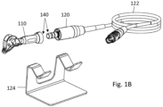
- Figs. 1A-1D illustrating a non-limiting example of a medical apparatus 100 configured according to the present invention.
- the medical apparatus 100 is configured for use in procedures involving tissue removal from a body organ, e.g. removing tissue from an eye such as to create a channel in the sclera tissue of the eye to allow draining of extra fluid accumulating inside the eye, a symptom that causes various medical conditions and/or complications.
- the apparatus 100 includes a hand-held probe device 110 which includes a rotatable cutting/surgical tool that cuts and removes the tissue, and a rotating motor device 120 that causes rotational movement of the cutting tool to remove the tissue.
- the apparatus 100 can also include, as shown, a control unit 130 that controls the operation of the rotating motor device and the cutting tool. Also shown in the figures, an optional stand 124 configured to safely hold the hand-held probe device when not being in use, and an optional pedal 134 by which a user can activate the control unit and/or the rotating motor.
- the hand-held probe 110 includes, on the outside, a housing 111 extending between a proximal end PE and a distal end DE, and a rotatable cutting tool 116 extending distally from the distal end of the housing.
- a proximal end PE indicates the patient side
- proximal indicates the operator/physician side.
- the rotatable cutting tool 116 is configured for cutting and removing tissue during rotation.
- the cutting tool 116 can be configured as described in WO2013186779 titled “Medical Device, Assembly and Method for Creating a Channel in Soft Tissue” and in WO2015145444 titled “Medical Device for Tissue Removal", both assigned to the assignee of the present invention.
- the housing of the hand-held probe encloses therein a transmission assembly configured to transmit rotational power from the rotating motor device 120 to the cutting tool 116 to thereby cause its rotation.
- a transmission assembly is described herein below with reference to Fig. 1D .
- the housing of the hand-held probe device can be formed as an integral member having a unibody configuration or it can be formed from more than one part, e.g. two parts. In either case, the housing can have more than one longitudinal axis along its length, between the proximal and distal ends. Having a plurality of longitudinal axes can be useful in that it enhances flexibility and access of the rotatable cutting tool to the treated organ in the three dimensional space. By tilting the housing at at-least one point along its length or by including two or more successive parts inclined by predetermined angles there between, with respect to each other, the three dimensional orientation of the probe as well as the cutting tool with respect to a treatment surface, being the organ's surface faced by the cutting tool, can be controlled.
- the housing includes an elongated body 112 at a proximal side (i.e. at the side of the user, far from the patient) and a head body 114, on which the rotatable cutting tool 116 is mounted, at a distal side (at the side of the patient, far from the user).
- the head 114 is oriented with a predetermined angle ⁇ with respect to the elongated body 112.
- the predetermined angle ⁇ can be defined in several ways.
- the predetermined angle ⁇ is chosen based on the specific medical application to enable effective and comfortable access to the tissue removal site, in other words it is chosen to provide better or optimal ergonomics for holding the device with respect to the tissue treatment site. Consequently, the predetermined angle is selected to enable access of the cutting tool 116 to every point on the body organ, taking into account the curviness of the organ/treatment surface, while the user holds the probe 110 with his hand.
- the predetermined angle ⁇ is determined based on several factors, including, inter alia, absolute lengths of the elongated body and the head, or the relative length between them; length of the cutting tool; anatomy of the treated organ and its surrounding.
- the value of ⁇ is typically equal to or larger than 90° up to a maximum of 180°. In the case of treating the eye, ⁇ is chosen to be close or equal to 135°.
- the whole hand-held probe 110 is disposable, such that it is used once and on one patient at a time.
- the whole probe 110 is made from materials that enable its disposal, such as different medical grade polymers, e.g. biocompatible polymers, with the exception of the cutting tool being made from biocompatible metal, ceramic or the like.
- the probe housing can be made from Polycarbonate (plastic parts), and the surgical tool from Corrosion Resistance Steel (CRES) 420F.
- Fig. 1D illustrates a non-limiting example of a transmission assembly 150 configured according to the invention.
- the transmission assembly which is accommodated inside the housing 111, e.g. the elongated body 112 and the head body 114, is made from light-weight and disposable, yet durable materials, such as polymers.
- the transmission assembly is designed and selected to withstand rotational speed of tens of thousands of rpm. In specific situations, as when removing soft tissue as the sclera in the eye, the speed is chosen to be around 8,000 rpm, which is sufficient but not oversized. Further, the transmission assembly enables effective transmission of the rotational power and includes minimum number of separate elements to achieve this.
- the transmission assembly 150 includes three parts: a clutch 146, an inlet shaft 152 coupled to the clutch and an outlet shaft 154 coupled to the inlet shaft.
- the distal portion of the inlet shaft 152 includes an inlet gear 156 which is coupled to an outlet gear 158 formed at the proximal portion of the outlet shaft.
- the transmission assembly exerts both rotational and forward forces on the cutting tool 116, thus enhancing attachment of the head body, and the cutting tool, to the body organ during treatment.
- the outlet shaft 154 has certain axial lash, and the gear profile creates a force vector directed forwardly to the distal direction.
- the rotating motor 120 connects, by its distal side, to the proximal end (PE in Fig. 1C ) of the probe 110, via the connection assembly 140 which is located at the proximal end of the probe and the distal end of the rotating motor, to thereby cause rotation of the cutting tool 116 via the transmission assembly passing inside the probe's housing.
- the rotating motor can include an integrated sensor such as a magnetic, optical or other kind of encoder.
- the configuration may be such that the encoder has a magnet with numerous polarities connected to the rotor part of the motor. Reading of the magnet polarities change is done by dedicated sensors, e.g. HOLE sensors, which are static and assembled inside the housing of the rotating motor.
- the sensor can be responsible for motor speed detection, rotation direction detection and number of rounds calculation.
- the motor type can be a brush or brushless motor or any other suitable kind.
- the control unit 130 controls the operation of the motor 120 via a connection 122, which in the shown example is a wired connection. In some embodiments, the connection can be wireless. As will be further detailed below, the control unit 130 activates the motor 120 and causes the rotation of the cutting tool 116 in response to a function selection made by the user via a control panel 132 on the control unit 130. In some embodiments, as will be further described below, the control panel 132 includes a touch screen to select activation functions and/or parameters.
- the apparatus 100 further includes a pedal 134 which the user presses down by his foot to activate the rotating motor, based on a function preselected on the control unit 130.
- the pedal is connected to the control unit via a connection 136, which in this example is a wired connection, however a wireless connection can be equally used.
- the pedal can be positioned inside an enclosing housing EH that minimizes accidental foot-pressing. It is only when the user inserts his foot inside the enclosing housing that he can press the pedal. As a result, unintentional pressing and activation of the rotating cutting tool is avoided.
- the enclosing housing functions as a guide for the operator. When the operator is focused on the patient and microscope he is able to find the pedal enclosure and to navigate his foot directly inside without the help of others.
- the apparatus of the invention enables independent and fully-functional usage by the physician alone. Using a pedal enhances this by allowing the physician to independently use the apparatus by holding the probe in one hand and keeping the other hand free which he can then use to hold the patient or to hold another accessory/device needed in the process.
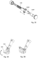
- connection assembly 140 configured according to the present invention, according to the invention, the connection assembly allows connecting the rotating motor 120 to the probe 110 in at least two orientations, relative to each other.
- the connection assembly is typically distributed between the hand-held probe, at its proximal end, and the rotating motor, at its distal side.
- the connection assembly 140 provides a reversible connection between the motor and the probe, i.e. it allows connection between both devices in two opposite (180°) orientations. As shown in Figs.
- the motor 120 has at its distal side, the side connecting to the probe, one of the two elements of the connection assembly, where a hollow rod 142 extends distally and in which a rotatable shaft 144 is installed.
- An exploded view is shown in Fig. 2B .
- the rotatable shaft 144 connects at its proximal end to the rotating motor 120 so as to transmit the rotational movement down the way to the cutting tool 116.
- the probe 110 includes at its proximal side the clutch 146 forming the second element of the connection assembly 140. As can be seen in Fig.
- the clutch 146 and the rotatable shaft 144 engage together in a male-female engagement mechanism, such that two protrusions 144P on the shaft 144 engage with two corresponding depressions 146D formed in the proximal end of the clutch 146.
- the engagement between the protrusions and the depressions is further illustrated in Fig. 2D which shows a longitudinal cross-sectional view of the clutch 146.
- the two protrusions 144P, as well as the two depressions 146D are identical and formed in a 180° with respect to each other.
- the connection is reversible and the probe and the motor are connectable to each other even if one is turned with a 180° with respect to the other during the engagement process.
- the protrusions and the corresponding depressions may be more than two, and in such a case they can be equally spaced from each other along the perimeter of the base of the clutch 146 and the shaft 144.
- connection assembly enables effortless and seamless attachment between the probe and the motor, such that the user does not need to turn either in order to align them or look at the end sides of the probe and motor when he/she attaches them.
- connection assembly includes axial or rotational movement of one of the two engaging elements with respect to the other.
- the clutch 146 is freely movable with respect to the probe 110 both axially and azimuthally.
- the motor is designed to work in a constant speed while it allows different output speeds for the transmission assembly and the cutting tool.
- the internal rotating parts engage as described, the outer housings of the motor device and the hand-held disposable device are not necessarily engaged. In one specific case, they are free to turn with respect to each other. This feature enhances the manageability of the probe by the user as it prevents or at least minimizes parasite moments which might be caused by the wired connection 122 when the probe and motor devices are moved by the user.
- Figs. 3A-3F illustrating a non-limiting example of a cover used with the disposable probe to keep the cutting tool safely covered when not in use, so to prevent accidental injury.
- the cover is configured to move in a predefined spatial path between a closed state covering the cutting tool and an open state revealing the cutting tool while still being attached to the head body of the probe.
- the cover enhances the safety further as it needs to pass a threshold distance along the spatial path in order to finally stay open, otherwise it returns back autonomously to its closed state.
- Additional safety measure is guaranteed since the cover does not detach from the probe unless it is in its open state, therefore accidental encounter with the cutting tool is prevented or at least minimized, inter alia because the direction of detachment is different from the axis of cutting tool, such that even during an unsuccessful removal of the cover, the user's hand does not accidentally move towards the cutting tool or at least its sharp apex. Yet further, additional safety is guaranteed by a safety locking mechanism which keeps the closed cover in place as long as no force is applied on it in order to open it.
- the cover 160 moves in a curved path, e.g. circular or semi-circular, around a hinge point 162 formed by a dent in the probe's housing, e.g. in the head body, to reveal the cutting tool.
- the cover 160 moves upwards, and not downwards, to facilitate its removal by the user.
- the cover's front reaches a certain position, it can be pulled off the probe. If the cover does not pass a predetermined distance towards its open state, it returns back to its closed state, such that it cannot be kept in a partially opened state in which the risk for accidental injury increases.
- the threshold safety mechanism can be implemented in different ways, such as by providing a spring that acts against the movement until it loses its elasticity, or until the cover is locked at its open state by a suitable protrusion that prevent its back movement.
- the threshold safety is achieved by the special structure of the side bars which act like springs, pushing the cover 160 towards the front of the probe if the cover does not reach the open state and get locked therein.
- the probe includes a locking safety mechanism which keeps the cover closed and prevents its accidental opening.
- a safety mechanism is achieved in the described example by providing a depression 166 in the probe's housing, such as a dent in the head body, which traps the side bars 164 and keeps them in a closed state, as shown in Figs. 3E and 3F . Opening the cover requires overcoming a protrusion 168 such that the side bars spread to climb over the protrusions 168 on both sides.
- the apparatus includes an electrical safety mechanism.
- the control unit activates the rotating cutting tool after receiving an input of a predetermined duration from the user.
- the input from the user can be provided via the control panel, e.g. by pressing an icon, or the provided pedal, for a predetermined duration. For example, when a pedal is provided, if the user presses the pedal for a period shorter than a predetermined period (e.g. half a second), the control unit does not activate the cutting tool. This helps in minimizing unintentional activation of the cutting tool.
- the present invention enhances the ergonomics of the probe to enable convenient, effective and controlled usage. Such requirements are especially important when treating sensitive organs such as the eye, because precise orientation of the probe and control over the power exerted by the operator are important.
- FIGs. 4A-4B illustrating non-limiting examples of ergonomics enhancing features.
- the probe 110 includes an ergonomic holding portion 170 at its distal side, which is aimed at facilitating the probe's grasping.
- the holding portion includes dedicated depressions 172 and 174 for positioning the index finger and the thumb respectively.
- the holding portion also includes a protrusion 176, in the vicinity of the depression 172, which acts as a pointer when the user pushes his index finger against it.
- the probe of the invention e.g. its holding portion, is configured to be ambidextrous, equally used by both right and left handed users.
- Fig. 4A shows a right hand holding the probe and
- Fig. 4B shows a left hand holding the probe.
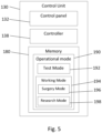
- Fig. 5 illustrating non-limiting examples of the control unit of the apparatus with the included control panel which can be in the form of a touch screen configured to enable controlling the operation of the apparatus.
- the control unit is a computing device that controls the operational mode of the apparatus including treatment parameters or functions of the surgical process as well as a test process.
- a schematic illustration of the components of the control unit 130 is shown.
- the control unit 130 includes the control panel 132 which is configured to enable the user to select a desired operational mode 190 saved in a memory 180.
- a controller 138 configured to execute the chosen operational mode, including parameters or functions, is included in the control unit and connected to the memory 180.
- the operational modes 190 include a test mode 192 and a working mode 194, the latter includes a surgery working mode 196 and a research working mode 198.
- the control unit 130 utilizing the controller 138, continuously monitors the operation of the apparatus parts to insure normal operation of the apparatus. For example, the following are monitored: connection between the different parts (the motor and probe, the motor and control unit, the control unit and foot switch (pedal)), the speed of the motor, the time of pressing the pedal by the user, number of motor activations as an indicator for motor life time (e.g. 250 cycles) which is limited due to sterilization load.
- the apparatus can include suitable sensors (not shown) which deliver information to the controller 138 about the operation of the apparatus and its different parts, including the monitored parameters described above.
- One example is the magnetic encoder described above with respect to the rotating motor device.
- the controller sends signals (e.g.
- the controller 138 may include a programmable chip enabling to add or modify features of the controller.
- the test mode 192 can be a self-test mode which runs automatically each time the apparatus is turned on or each time an operational fault is detected by the monitoring controller, such as a fault in the connection between the control unit and the motor. Additionally or alternatively, the test mode 192 can run upon user's request by selecting it via the control panel 132.
- the controller 138 outputs a suitable alert according to the error found during the running of the self-test or according to the continuous monitoring applied during the working modes 194 as described above.
- the test mode examines the speed of the motor in order to detect failures or alert about end of life. In such case, the controller activates the motor for a predetermined time period and counts the number of rounds the motor performed and compares the result to a value saved in the memory 180.
- the controller If the result is out of a predefined range around the saved value, the controller generates a fault alert.
- the alert may, for example, indicate that the motor may have completed its life cycle and needs to be replaced, that the cable connector is not working as specified or that the sensor monitoring the motor is not working as specified.
- the controller 138 can be programmed to automatically move the apparatus to the working mode 194.
- the surgery working mode 196 is selected.
- This mode is a predefined mode which has the operational parameters of the apparatus fixed at predetermined recommended values that suit the specific surgical operation, the body organ specifications, the treated population/race or the treated species.
- the control unit can be programmed to include a plurality of surgery working modes, each with saved predefined operational parameters, which the operator can access by a mere press of a button on the control panel (e.g. an icon/tile on a touch screen). For example, when removing tissue from the sclera tissue in the eye, the motor speed is determined to be 8000 RPM and the time for each activation is determined to be 0.4 sec. However, when treating animals, e.g. horses or dogs who suffer from excessive pressure in their eyes, the values are different and specific to the treated species.
- the saved values of the operational parameters can be recommended values chosen based on experience and/or experiments.
- the apparatus can be put into a research working mode, which enables the user to control and change the parameters values.
- accessing the research working mode can be protected with a pin or password.
- the parameters which can be controlled include, inter alia, the speed of rotation, the duration of rotation, the direction of rotation (clockwise, counter clockwise, or a combination thereof) and the transmission ratio between the motor and the cutting tool. The user can then save a new working mode including the values of the parameters that he used in the research to be easily accessed again in the future.
- the control panel includes a friendly user-interface that allows the user to choose the operational mode of the device as well as the different operational parameters.
- the present invention provides an apparatus that enables a comprehensive, powerful and safe solution for tissue removal from the body.
- the invention may be powerfully integrated within other treatment apparatuses, thereby saving place and complexity inside the operating rooms.
Landscapes
- Health & Medical Sciences (AREA)
- Life Sciences & Earth Sciences (AREA)
- Surgery (AREA)
- Ophthalmology & Optometry (AREA)
- Engineering & Computer Science (AREA)
- Biomedical Technology (AREA)
- Veterinary Medicine (AREA)
- Heart & Thoracic Surgery (AREA)
- Animal Behavior & Ethology (AREA)
- General Health & Medical Sciences (AREA)
- Public Health (AREA)
- Nuclear Medicine, Radiotherapy & Molecular Imaging (AREA)
- Vascular Medicine (AREA)
- Medical Informatics (AREA)
- Molecular Biology (AREA)
- Orthopedic Medicine & Surgery (AREA)
- Anesthesiology (AREA)
- Hematology (AREA)
- Environmental & Geological Engineering (AREA)
- Surgical Instruments (AREA)
- Physics & Mathematics (AREA)
- General Physics & Mathematics (AREA)
- Peptides Or Proteins (AREA)
Priority Applications (1)
| Application Number | Priority Date | Filing Date | Title |
|---|---|---|---|
| EP24218339.0A EP4501257A3 (de) | 2016-09-27 | 2016-09-27 | Vorrichtung zur gewebeentfernung |
Applications Claiming Priority (3)
| Application Number | Priority Date | Filing Date | Title |
|---|---|---|---|
| PCT/IL2016/051063 WO2018060983A1 (en) | 2016-09-27 | 2016-09-27 | Apparatus for tissue removal |
| EP16917599.9A EP3518845B1 (de) | 2016-09-27 | 2016-09-27 | Vorrichtung zur gewebeentnahme |
| EP24218339.0A EP4501257A3 (de) | 2016-09-27 | 2016-09-27 | Vorrichtung zur gewebeentfernung |
Related Parent Applications (1)
| Application Number | Title | Priority Date | Filing Date |
|---|---|---|---|
| EP16917599.9A Division EP3518845B1 (de) | 2016-09-27 | 2016-09-27 | Vorrichtung zur gewebeentnahme |
Publications (2)
| Publication Number | Publication Date |
|---|---|
| EP4501257A2 true EP4501257A2 (de) | 2025-02-05 |
| EP4501257A3 EP4501257A3 (de) | 2025-04-09 |
Family
ID=61760170
Family Applications (2)
| Application Number | Title | Priority Date | Filing Date |
|---|---|---|---|
| EP16917599.9A Active EP3518845B1 (de) | 2016-09-27 | 2016-09-27 | Vorrichtung zur gewebeentnahme |
| EP24218339.0A Pending EP4501257A3 (de) | 2016-09-27 | 2016-09-27 | Vorrichtung zur gewebeentfernung |
Family Applications Before (1)
| Application Number | Title | Priority Date | Filing Date |
|---|---|---|---|
| EP16917599.9A Active EP3518845B1 (de) | 2016-09-27 | 2016-09-27 | Vorrichtung zur gewebeentnahme |
Country Status (12)
| Country | Link |
|---|---|
| US (2) | US11471325B2 (de) |
| EP (2) | EP3518845B1 (de) |
| JP (1) | JP6899566B2 (de) |
| KR (1) | KR102425403B1 (de) |
| CN (1) | CN109862855B (de) |
| BR (1) | BR112019005893B1 (de) |
| CA (1) | CA3038016C (de) |
| ES (1) | ES3009895T3 (de) |
| IL (3) | IL264892B2 (de) |
| MX (1) | MX2019003380A (de) |
| RU (1) | RU2722450C1 (de) |
| WO (1) | WO2018060983A1 (de) |
Families Citing this family (7)
| Publication number | Priority date | Publication date | Assignee | Title |
|---|---|---|---|---|
| US11666780B2 (en) | 2017-09-07 | 2023-06-06 | Radiance Therapeutics, Inc. | Methods, systems, and compositions for maintaining functioning drainage blebs associated with minimally invasive micro sclerostomy |
| GB201714392D0 (en) | 2017-09-07 | 2017-10-25 | Marsteller Laurence | Methods and devices for treating glaucoma |
| EP3886777B1 (de) | 2018-11-29 | 2025-05-07 | Radiance Therapeutics, Inc. | Ophthalmische brachytherapiesysteme und vorrichtungen zur anwendung von beta-strahlung |
| USD933226S1 (en) | 2018-11-29 | 2021-10-12 | Radiance Therapeutics, Inc. | Ophthalmic brachytherapy set |
| USD933225S1 (en) | 2018-11-29 | 2021-10-12 | Radiance Therapeutics, Inc. | Ophthalmic brachytherapy device |
| USD1076086S1 (en) | 2021-11-23 | 2025-05-20 | Radiance Therapeutics, Inc. | Opthalmic brachytherapy device |
| USD1076085S1 (en) | 2021-11-23 | 2025-05-20 | Radiance Therapeutics, Inc. | Opthalmic brachytherapy device |
Citations (3)
| Publication number | Priority date | Publication date | Assignee | Title |
|---|---|---|---|---|
| US20020120285A1 (en) | 2001-02-23 | 2002-08-29 | Ras Holding Corp | Surgical blade for use with a surgical tool for making incisions for scleral eye implants |
| WO2013186779A2 (en) | 2012-06-14 | 2013-12-19 | Sanoculis Ltd. | A medical device, assembly and method for creating a channel in soft tissue |
| WO2015145444A2 (en) | 2014-03-27 | 2015-10-01 | Sanoculis Ltd. | Medical device for tissue removal |
Family Cites Families (27)
| Publication number | Priority date | Publication date | Assignee | Title |
|---|---|---|---|---|
| US3847154A (en) * | 1972-09-22 | 1974-11-12 | Weck & Co Edward | Surgical drill with detachable hand-piece |
| US5421819A (en) * | 1992-08-12 | 1995-06-06 | Vidamed, Inc. | Medical probe device |
| RU2050152C1 (ru) * | 1986-11-27 | 1995-12-20 | Сумимото Бейклайт Компани Лимитед | Ультразвуковой хирургический аппарат |
| CN2130220Y (zh) * | 1992-05-18 | 1993-04-21 | 柏映庆 | 汽车可控式复合离合器 |
| CN2149267Y (zh) * | 1992-09-08 | 1993-12-15 | 沈阳重型机器厂 | 立式车床单向旋转加工螺纹装置 |
| JPH0847505A (ja) * | 1994-08-05 | 1996-02-20 | Yoshio Nagata | 水晶体前嚢切開具 |
| US5634918A (en) * | 1994-10-26 | 1997-06-03 | Grieshaber & Co. Ag Schaffhausen | Ophthalmic surgical instrument |
| BR9709071A (pt) | 1996-05-09 | 2000-01-11 | Itos Innovatite Technology In | o sistema inclui em adição um dispositivo de remoção de catarata (crd) (204) para fragmentar a catarata enquanto ela é congelada pelo criomanipulador. o crd inclui uma unidade de perfuração (230) possuindo uma lâmida de perfuração rotativa (246) para fragmentar a catarata e um alojamento possuindo condutos de aspiração e irrigação (256). um processo de uso do sistema inclui o congelamento-agarramento e a fragmentação de catarata seguidos pela irrigação e aspiração do fluido e dos fragmentos de catarata com o crd e/ou o criomanipulador. |
| US6328747B1 (en) * | 1996-05-09 | 2001-12-11 | Itos Innovative Technology In Ocular Surgery, Ltd. | Method and a system for performing cataract surgery |
| US6749588B1 (en) * | 1998-04-09 | 2004-06-15 | Becton Dickinson And Company | Catheter and introducer needle assembly with needle shield |
| WO2000016832A1 (en) | 1998-09-23 | 2000-03-30 | Koh Lawrence R | Needle point guard safety cap assembly |
| WO2005011496A1 (ja) * | 2003-07-31 | 2005-02-10 | Matsushita Electric Industrial Co., Ltd. | 穿刺器具、穿刺針カートリッジ、穿刺器具セット及び穿刺針廃棄器具 |
| CN1304768C (zh) * | 2004-08-09 | 2007-03-14 | 葛玉明 | 摩嵌式离合器及其制造方法 |
| TWI369970B (en) * | 2004-10-20 | 2012-08-11 | Beaver Visitec Int Us Inc | Surgical knife safety handle having user operable lock |
| US7458903B2 (en) | 2006-06-08 | 2008-12-02 | Eaton Corporation | Hand grip and method of making same |
| US8038692B2 (en) * | 2006-10-31 | 2011-10-18 | Novartis Ag | Modular design for ophthalmic surgical probe |
| CN201023367Y (zh) * | 2006-11-13 | 2008-02-20 | 赵金林 | 指法笔 |
| US9421030B2 (en) * | 2008-11-14 | 2016-08-23 | Cole Isolation Technique, Llc | Follicular dissection device and method |
| CN101507850B (zh) * | 2009-03-19 | 2011-04-20 | 钟炳棠 | 安全注射针套 |
| JP4970488B2 (ja) | 2009-03-30 | 2012-07-04 | 京楽産業.株式会社 | 遊技機、主制御部、主制御基板、中間部、周辺基板、認証方法及び認証プログラム |
| US20110160740A1 (en) | 2009-12-28 | 2011-06-30 | Acclarent, Inc. | Tissue Removal in The Paranasal Sinus and Nasal Cavity |
| US9421129B2 (en) * | 2012-04-02 | 2016-08-23 | Ocuject, Llc | Intraocular delivery devices and methods therefor |
| WO2014074764A1 (en) * | 2012-11-08 | 2014-05-15 | Covidien Lp | Tissue-removing catheter including operational control mechanism |
| CN105073023A (zh) * | 2012-12-20 | 2015-11-18 | 脊柱诊察公司 | 椎间盘切除装置和方法 |
| CN103751889A (zh) * | 2014-01-21 | 2014-04-30 | 淮安市恒春医疗器材有限公司 | 安全自毁式注射器 |
| SG11201607021VA (en) * | 2014-02-26 | 2016-09-29 | Allergan Inc | Intraocular implant delivery apparatus and methods of use thereof |
| JP6838059B2 (ja) * | 2015-10-27 | 2021-03-03 | デビコー・メディカル・プロダクツ・インコーポレイテッドDevicor Medical Products, Inc. | 外科用プローブ装置、ならびにそれを使用するシステム及び方法 |
-
2016
- 2016-09-27 KR KR1020197012077A patent/KR102425403B1/ko active Active
- 2016-09-27 CN CN201680089452.9A patent/CN109862855B/zh active Active
- 2016-09-27 EP EP16917599.9A patent/EP3518845B1/de active Active
- 2016-09-27 MX MX2019003380A patent/MX2019003380A/es unknown
- 2016-09-27 BR BR112019005893-1A patent/BR112019005893B1/pt active IP Right Grant
- 2016-09-27 IL IL264892A patent/IL264892B2/en unknown
- 2016-09-27 EP EP24218339.0A patent/EP4501257A3/de active Pending
- 2016-09-27 CA CA3038016A patent/CA3038016C/en active Active
- 2016-09-27 US US16/337,288 patent/US11471325B2/en active Active
- 2016-09-27 IL IL308855A patent/IL308855B1/en unknown
- 2016-09-27 ES ES16917599T patent/ES3009895T3/es active Active
- 2016-09-27 JP JP2019515828A patent/JP6899566B2/ja active Active
- 2016-09-27 IL IL323070A patent/IL323070A/en unknown
- 2016-09-27 WO PCT/IL2016/051063 patent/WO2018060983A1/en not_active Ceased
- 2016-09-27 RU RU2019110429A patent/RU2722450C1/ru active
-
2022
- 2022-10-12 US US17/964,299 patent/US12336935B2/en active Active
Patent Citations (3)
| Publication number | Priority date | Publication date | Assignee | Title |
|---|---|---|---|---|
| US20020120285A1 (en) | 2001-02-23 | 2002-08-29 | Ras Holding Corp | Surgical blade for use with a surgical tool for making incisions for scleral eye implants |
| WO2013186779A2 (en) | 2012-06-14 | 2013-12-19 | Sanoculis Ltd. | A medical device, assembly and method for creating a channel in soft tissue |
| WO2015145444A2 (en) | 2014-03-27 | 2015-10-01 | Sanoculis Ltd. | Medical device for tissue removal |
Also Published As
| Publication number | Publication date |
|---|---|
| EP3518845B1 (de) | 2024-12-11 |
| EP3518845A4 (de) | 2020-06-17 |
| CA3038016C (en) | 2023-10-03 |
| ES3009895T3 (en) | 2025-03-31 |
| US20200030148A1 (en) | 2020-01-30 |
| KR102425403B1 (ko) | 2022-07-26 |
| BR112019005893B1 (pt) | 2023-03-21 |
| US12336935B2 (en) | 2025-06-24 |
| EP3518845A1 (de) | 2019-08-07 |
| JP2019532707A (ja) | 2019-11-14 |
| CN109862855B (zh) | 2023-10-27 |
| BR112019005893A2 (pt) | 2019-06-11 |
| CA3038016A1 (en) | 2018-04-05 |
| IL308855A (en) | 2024-01-01 |
| US20230146263A1 (en) | 2023-05-11 |
| RU2722450C1 (ru) | 2020-06-01 |
| US11471325B2 (en) | 2022-10-18 |
| CN109862855A (zh) | 2019-06-07 |
| JP6899566B2 (ja) | 2021-07-07 |
| WO2018060983A1 (en) | 2018-04-05 |
| KR20190091259A (ko) | 2019-08-05 |
| IL308855B1 (en) | 2025-09-01 |
| MX2019003380A (es) | 2019-06-03 |
| IL264892B2 (en) | 2024-04-01 |
| IL264892B1 (en) | 2023-12-01 |
| EP4501257A3 (de) | 2025-04-09 |
| EP3518845C0 (de) | 2024-12-11 |
| IL264892A (de) | 2019-04-30 |
| IL323070A (en) | 2025-10-01 |
Similar Documents
| Publication | Publication Date | Title |
|---|---|---|
| US12336935B2 (en) | Apparatus for tissue removal | |
| US7252660B2 (en) | Multifunctional instrument for use in microinvasive surgery | |
| JP7070952B2 (ja) | 長尺の医療機器を操作するためのシステムおよび方法 | |
| WO2012057807A1 (en) | Rotational driver | |
| EP3432814B1 (de) | Chirurgisches instrument mit schneidanordnung mit griff | |
| AU2007210912A1 (en) | Ultrasonic cutting tool | |
| KR101267914B1 (ko) | 외과 수술 로봇 조작 장치 | |
| US12408916B2 (en) | System and method for performing tissue treatment using powered treatment devices | |
| JP4008008B2 (ja) | 超音波凝固切開装置 | |
| JP3782598B2 (ja) | 超音波凝固切開装置 | |
| US12491128B2 (en) | System and method for performing tissue treatment using powered treatment devices | |
| US20230172799A1 (en) | System and method for performing tissue treatment using powered treatment devices | |
| CA3241945A1 (en) | System and method for performing tissue treatment using powered treatment devices |
Legal Events
| Date | Code | Title | Description |
|---|---|---|---|
| PUAI | Public reference made under article 153(3) epc to a published international application that has entered the european phase |
Free format text: ORIGINAL CODE: 0009012 |
|
| STAA | Information on the status of an ep patent application or granted ep patent |
Free format text: STATUS: THE APPLICATION HAS BEEN PUBLISHED |
|
| AC | Divisional application: reference to earlier application |
Ref document number: 3518845 Country of ref document: EP Kind code of ref document: P |
|
| AK | Designated contracting states |
Kind code of ref document: A2 Designated state(s): AL AT BE BG CH CY CZ DE DK EE ES FI FR GB GR HR HU IE IS IT LI LT LU LV MC MK MT NL NO PL PT RO RS SE SI SK SM TR |
|
| REG | Reference to a national code |
Ref country code: DE Ref legal event code: R079 Free format text: PREVIOUS MAIN CLASS: A61B0017320000 Ipc: A61F0009007000 |
|
| PUAL | Search report despatched |
Free format text: ORIGINAL CODE: 0009013 |
|
| AK | Designated contracting states |
Kind code of ref document: A3 Designated state(s): AL AT BE BG CH CY CZ DE DK EE ES FI FR GB GR HR HU IE IS IT LI LT LU LV MC MK MT NL NO PL PT RO RS SE SI SK SM TR |
|
| RIC1 | Information provided on ipc code assigned before grant |
Ipc: A61B 17/32 20060101ALI20250304BHEP Ipc: A61F 9/007 20060101AFI20250304BHEP |
|
| STAA | Information on the status of an ep patent application or granted ep patent |
Free format text: STATUS: REQUEST FOR EXAMINATION WAS MADE |
|
| 17P | Request for examination filed |
Effective date: 20250908 |