EP4498005A1 - Klimaanlage - Google Patents
Klimaanlage Download PDFInfo
- Publication number
- EP4498005A1 EP4498005A1 EP22934881.8A EP22934881A EP4498005A1 EP 4498005 A1 EP4498005 A1 EP 4498005A1 EP 22934881 A EP22934881 A EP 22934881A EP 4498005 A1 EP4498005 A1 EP 4498005A1
- Authority
- EP
- European Patent Office
- Prior art keywords
- air
- housing
- disposed
- nano water
- emitter electrode
- Prior art date
- Legal status (The legal status is an assumption and is not a legal conclusion. Google has not performed a legal analysis and makes no representation as to the accuracy of the status listed.)
- Pending
Links
Images


Classifications
-
- F—MECHANICAL ENGINEERING; LIGHTING; HEATING; WEAPONS; BLASTING
- F24—HEATING; RANGES; VENTILATING
- F24F—AIR-CONDITIONING; AIR-HUMIDIFICATION; VENTILATION; USE OF AIR CURRENTS FOR SCREENING
- F24F8/00—Treatment, e.g. purification, of air supplied to human living or working spaces otherwise than by heating, cooling, humidifying or drying
- F24F8/30—Treatment, e.g. purification, of air supplied to human living or working spaces otherwise than by heating, cooling, humidifying or drying by ionisation
-
- F—MECHANICAL ENGINEERING; LIGHTING; HEATING; WEAPONS; BLASTING
- F24—HEATING; RANGES; VENTILATING
- F24F—AIR-CONDITIONING; AIR-HUMIDIFICATION; VENTILATION; USE OF AIR CURRENTS FOR SCREENING
- F24F1/00—Room units for air-conditioning, e.g. separate or self-contained units or units receiving primary air from a central station
- F24F1/0007—Indoor units, e.g. fan coil units
- F24F1/0043—Indoor units, e.g. fan coil units characterised by mounting arrangements
- F24F1/0047—Indoor units, e.g. fan coil units characterised by mounting arrangements mounted in the ceiling or at the ceiling
-
- F—MECHANICAL ENGINEERING; LIGHTING; HEATING; WEAPONS; BLASTING
- F24—HEATING; RANGES; VENTILATING
- F24F—AIR-CONDITIONING; AIR-HUMIDIFICATION; VENTILATION; USE OF AIR CURRENTS FOR SCREENING
- F24F1/00—Room units for air-conditioning, e.g. separate or self-contained units or units receiving primary air from a central station
- F24F1/0007—Indoor units, e.g. fan coil units
- F24F1/0071—Indoor units, e.g. fan coil units with means for purifying supplied air
- F24F1/0076—Indoor units, e.g. fan coil units with means for purifying supplied air by electric means, e.g. ionisers or electrostatic separators
-
- F—MECHANICAL ENGINEERING; LIGHTING; HEATING; WEAPONS; BLASTING
- F24—HEATING; RANGES; VENTILATING
- F24F—AIR-CONDITIONING; AIR-HUMIDIFICATION; VENTILATION; USE OF AIR CURRENTS FOR SCREENING
- F24F13/00—Details common to, or for air-conditioning, air-humidification, ventilation or use of air currents for screening
- F24F13/22—Means for preventing condensation or evacuating condensate
-
- F—MECHANICAL ENGINEERING; LIGHTING; HEATING; WEAPONS; BLASTING
- F25—REFRIGERATION OR COOLING; COMBINED HEATING AND REFRIGERATION SYSTEMS; HEAT PUMP SYSTEMS; MANUFACTURE OR STORAGE OF ICE; LIQUEFACTION SOLIDIFICATION OF GASES
- F25B—REFRIGERATION MACHINES, PLANTS OR SYSTEMS; COMBINED HEATING AND REFRIGERATION SYSTEMS; HEAT PUMP SYSTEMS
- F25B13/00—Compression machines, plants or systems, with reversible cycle
Definitions
- the present disclosure relates to the field of air conditioning technologies, and in particular, to an air conditioner.
- Split air conditioner includes an indoor unit and an outdoor unit.
- the indoor unit and the outdoor unit are installed indoors and outdoors respectively, and are connected to each other through pipelines and wires.
- the air conditioners are also provided with air purification functions.
- the nano water ion generating apparatus is disposed at the air outlet and is configured to generate nano water ions with negative charges and hydroxyl radicals generated by ionized water.
- the nano water ion generating apparatus includes an emitter electrode and a refrigeration portion, the refrigeration portion is configured to generate condensed water for ionization the emitter electrode.
- the air duct includes a first air duct and a second air duct that are communicated to each other.
- the first air duct is further away from the air outlet than the second air duct, and a part of the air in the first air duct directly flows to the refrigeration portion through the piping box without exchanging heat with the indoor heat exchanger, so as to avoid a change in temperature and humidity of air at the air outlet from affecting a water condensation ability of the nano water ion generating apparatus.
- first and second are used for descriptive purposes only, and are not to be construed as indicating or implying a relative importance or implicitly indicating a number of indicated technical features. Therefore, features defined by “first” or “second” may explicitly or implicitly include one or more of the features.
- the term “a plurality of” or “the plurality of” means two or more unless otherwise specified.
- phrases "at least one of A, B, and C” has the same meaning as the phrase "at least one of A, B, or C", both including the following combinations of A, B, and C: only A, only B, only C, a combination of A and B, a combination of A and C, a combination of B and C, and a combination of A, B, and C.
- a and/or B includes the following three combinations: only A, only B, and a combination of A and B.
- parallel includes absolute parallelism and approximate parallelism, and an acceptable range of deviation of the approximate parallelism may be, for example, a deviation within 5°;
- perpendicular includes absolute perpendicularity and approximate perpendicularity, and an acceptable range of deviation of the approximate perpendicularity may also be, for example, a deviation within 5°.
- equal includes absolute equality and approximate equality, and an acceptable range of deviation of the approximate equality may be that, for example, a difference between the two that are equal is less than or equal to 5% of either of the two.
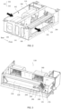
- an air conditioner is provided. As shown in FIG. 1A , the air conditioner 1000 includes an indoor unit 10 and an outdoor unit 20. The indoor unit 10 and the outdoor unit 20 are connected to each other through a pipe, so as to transport a refrigerant.
- the indoor unit 10 includes an indoor heat exchanger 130.
- the outdoor unit 20 includes an outdoor heat exchanger 21, a compressor 22, a four-way valve 23 and a throttling mechanism 24.
- the throttling mechanism 24 may also be provided in the indoor unit 10.
- the throttling mechanism 24 may be composed of at least one of a throttling valve, an expansion valve, or a pressure reducer.
- the throttling mechanism 24 may be composed of the expansion valve, the expansion valve and the throttling valve connected in series, or the expansion valve and the pressure reducer connected in series, and the present disclosure is not limited thereto.
- a refrigerant cycle is formed by the compressor 22, the outdoor heat exchanger 21, the throttling mechanism 24 and the indoor heat exchanger 130 connected in sequence.
- the refrigerant circulates in the refrigerant cycle and exchanges heat with the air through the outdoor heat exchanger 21 and the indoor heat exchanger 130, so as to achieve a cooling mode or a heating mode of the air conditioner 1000.
- the compressor 22 is configured to compress the refrigerant, so that a refrigerant with low temperature and low pressure is compressed to form a refrigerant with high temperature and high pressure.
- the outdoor heat exchanger 21 is configured to perform heat-exchange between outdoor air and the refrigerant conveyed in the outdoor heat exchanger 21.
- the outdoor heat exchanger 21 operates as a condenser in a cooling mode of the air conditioner 1000, so that the refrigerant compressed by the compressor 22 passes through the outdoor heat exchanger 21 to dissipate heat into the outdoor air to be condensed.
- the outdoor heat exchanger 21 operates as an evaporator in a heating mode of the air conditioner 1000, so that the decompressed refrigerant passes through the outdoor heat exchanger 21 to absorb heat in the outdoor air to be evaporated.
- the outdoor heat exchanger 21 further includes heat exchange fins, so as to enlarge a contact area between the outdoor air and the refrigerant conveyed in the outdoor heat exchanger 21, thereby improving heat exchange efficiency between the outdoor air and the refrigerant.
- the throttling mechanism 24 is connected between the outdoor heat exchanger 21 and the indoor heat exchanger 130, a pressure of a refrigerant flowing between the outdoor heat exchanger 21 and the indoor heat exchanger 130 is adjusted by an opening degree of the throttling mechanism 24, so as to adjust the flow rate of the refrigerant flowing between the outdoor heat exchanger 21 and the indoor heat exchanger 130.
- the flow rate and pressure of the refrigerant flowing between the outdoor heat exchanger 21 and the indoor heat exchanger 130 will affect the heat exchange performance of the outdoor heat exchanger 21 and the indoor heat exchanger 130.
- the throttling mechanism 24 may be an electronic valve.
- the opening degree of the throttling mechanism 24 may be adjustable, so as to control the flow rate and pressure of the refrigerant flowing through the throttling mechanism 24.
- the throttling mechanism 24 is configured to throttle a supercooled liquid refrigerant flowing out of the outdoor heat exchanger 21 into a gas-liquid two-phase refrigerant with low temperature and low pressure, and the flow direction of the refrigerant is shown by solid arrows in FIG. 1A .
- the throttling mechanism 24 is configured to throttle the supercooled liquid refrigerant flowing out of the indoor heat exchanger 130 into the gas-liquid two-phase refrigerant with low temperature and low pressure, and the flow direction of the refrigerant is shown by dashed arrows in FIG. 1A .
- the four-way valve 23 is connected in the refrigerant circle, and is configured to switch a flow direction of the refrigerant in the refrigerant circle, so that the air conditioner 1000 may perform the cooling mode or the heating mode.
- the indoor heat exchanger 130 is configured to perform heat-exchange between indoor air and the refrigerant conveyed in the indoor heat exchanger 130.
- the indoor heat exchanger 130 operates as an evaporator in a cooling mode of the air conditioner 1000, so that the refrigerant that has been heat-dissipated via the outdoor heat exchanger 21 passes through the indoor heat exchanger 130 to absorb heat in the indoor air to be evaporated.
- the indoor heat exchanger 130 operates as a condenser in a heating mode of the air conditioner 1000, so that the refrigerant that has absorbed heat via the outdoor heat exchanger 21 passes through the indoor heat exchanger 130 to dissipate heat into the indoor air to be condensed.
- the indoor heat exchanger 130 further includes heat exchange fins, so as to enlarge a contact area between the indoor air and the refrigerant conveyed in the indoor heat exchanger 130, thereby improving heat exchange efficiency between the indoor air and the refrigerant.
- the refrigerant when the air conditioner 1000 operates in the cooling mode, the refrigerant is compressed by the compressor 22 and becomes a superheated gaseous refrigerant with high temperature and high pressure, and the superheated gaseous refrigerant with high temperature and high pressure is discharged into the outdoor heat exchanger 21 for condensation.
- the superheated gaseous refrigerant In the outdoor heat exchanger 21, the superheated gaseous refrigerant is cooled into a supercooled liquid refrigerant, and the supercooled liquid refrigerant flows into the throttling mechanism 24.
- the throttling mechanism 24 may throttle the supercooled liquid refrigerant into the gas-liquid two-phase refrigerant with low temperature and low pressure.
- the gas-liquid two-phase refrigerant with low temperature and low pressure flows into the indoor heat exchanger 130 to evaporate and absorb heat.
- the refrigerant is evaporated into superheated gas again, and returned to a suction end of the compressor 22 to accomplish a cycle.
- the air conditioner 1000 when the air conditioner 1000 operates in the heating mode, after passing through the four-way valve 23, the gaseous refrigerant with high temperature and high pressure is directly discharged into the indoor heat exchanger 130 for heating. After being cooled into supercooled liquid refrigerant, the supercooled liquid refrigerant flows into the throttling mechanism 24, and is throttled into the gas-liquid two-phase refrigerant with low temperature and low pressure by the the throttling mechanism 24. The gas-liquid two-phase refrigerant with low temperature and low pressure flows into the outdoor heat exchanger 21 for heat absorption and evaporation.
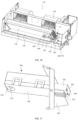
- the outer contour of the indoor unit 10 is formed by a first housing 100.
- the first housing 100 is provided with a return air inlet 110 on a side and an air outlet 120 on another side.
- the return air inlet 110 and the air outlet 120 are communicated to each other, so as to form an air duct, and the indoor heat exchanger 130 is disposed in the air duct formed by the communication between the return air inlet 110 and the air outlet 120.
- the indoor unit 10 includes a first partition plate 150, the first partition plate 150 is disposed in the first accommodating space 101 of the first housing 100, and is configured to divide the first accommodating space 101 into a first subspace 161 and a second subspace 162.
- the first subspace 161 may be a front cavity of the first accommodating space 101
- the second subspace 162 may be a rear cavity of the first accommodating space 101.
- the indoor unit 10 further includes a blower 140.
- the blower 140 is installed in the second subspace 162, and the return air inlet 110 is communicated to the second subspace 162.
- the indoor heat exchanger 130 is installed in the first subspace 161, and the air outlet 120 is communicated to the first subspace 161.
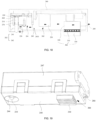
- the air duct of the indoor unit 10 includes a first air duct and a second air duct that are communicated with each other. And the first air duct is further away from the air outlet 120 than the second air duct.
- the first air duct is located on an upstream side of the indoor heat exchanger 130, and the second air duct is located on a downstream side of the indoor heat exchanger 130.
- some embodiments of the present disclosure make full use of the space in the piping box 170 and a first vent 1701 is provided on the piping box 170, so as to communicate the piping box 170 with the air outlet 120 through the first vent 1701.
- a part of air that flows into the air duct from the return air inlet 110 is not heat exchanged by the indoor heat exchanger 130, the part of air flows into the piping box 170 and then flows to a nano water ion generating apparatus 200 at the air outlet 120 through the first vent 1701.
- the nano water ion generating apparatus 200 is configured to generate nano water ions with negative charges and hydroxyl radicals generated by ionized water.
- Negative charges may make the particles in the air charged, and promote the particles in the air to agglomerate, which increases the volume and weight of the particles and then settle the particles to the ground; or, the charged particles may be adsorbed to the nearest zero potential (earth), so as to remove the particles in the air (e.g., PM2.5, etc.).
- the nano water ion generating apparatus 200 is disposed at the air outlet 120, and the nano water ions generated by the nano water ion generating apparatus 200 are directly blown into the indoor space to improve the air purification effect.
- the nano water ion generating apparatus 200 includes an emitter electrode 210, a refrigeration portion 220 and a power supply portion 230.
- the emitter electrode 210 is designed to be hydrophilic in order to direct the condensed water generated by the refrigeration portion 220 to its emitter tip. After the emitter electrode 210 is connected to the negative high voltage, negatively charged nano water ions may be ionized and excited at the emitter tip.
- the emitter electrode 210 includes a water-absorbing member, and bactericidal materials (e.g., silver ions, etc.) are added to the water-absorbing member.
- the emitter electrode 210 is charged by receiving the negative high voltage provided by the power supply portion 230.
- the water in the water-absorbing member in the emitter electrode 210 is excited by high-voltage ionization to generate nano water ions.
- the nano water ions carry negative charges and hydroxyl radicals generated by the ionized water.
- the refrigeration portion 220 is configured to generate condensed water.
- the nano water ion generating apparatus 200 includes a water storage gap 260.
- the water storage gap 260 is located between an end of the emitter electrode 210 and the refrigeration portion 220.
- the condensed water generated by the refrigeration portion 220 is stored in the water storage gap 260, and the emitter electrode 210 uses hydrophilicity to direct the condensed water in the water storage gap 260 to its emitter tip.
- the ability of the refrigeration portion 220 to generate condensed water is related to the temperature difference of the surrounding air. The greater the temperature difference, the stronger the ability to generate condensed water; on the contrary, the smaller the temperature difference, the weaker the ability to generate condensed water.
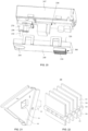
- the nano water ion generating apparatus 200 further includes a second housing 240 (i.e., the apparatus housing, see FIG. 17 ).
- the emitter electrode 210, the refrigeration portion 220, and the power supply portion 230 each are provided in the second housing 240.
- the second housing 240 may be made of insulation materials (e.g., polypropylene, etc.).
- the second housing 240 includes a nano water ion release port 244 for exposing the emitter tip of the emitter electrode 210.
- the nano water ion release port 244 faces the air outlet 120.
- the nano water ion generating apparatus 200 includes a second partition plate 243, the second partition plate 243 is disposed in a second accommodating space 202 of the second housing 240.
- the second partition plate 243 is configured to divide the second accommodating space 202 into a third subspace 241 and a fourth subspace 242, and the second partition plate 243 includes an opening 2431 for gas flow.
- the second housing 240 includes a bottom shell 247 and a cover 248.
- the bottom shell 247 includes a clamping portion 2471
- the cover 248 includes a buckle 2481.
- the fixed connection between the bottom shell 247 and the cover 248 may be implemented though the clamping between the buckle 2481 and the clamping portion 2471.
- the second housing 240 includes a wiring opening 245.
- the wiring opening 245 is provided on the side edge of the bottom shell 247 proximate to the cover 248, which is convenient for wiring.
- the nano water ion release port 244 is disposed on the cover 248.
- the refrigeration portion 220 is disposed at an end of the electrode fixing base 270 away from the cover 248, and the refrigeration portion 220 faces the electrode mounting hole 21A.
- the water storage gap 260 is formed among the refrigeration portion 220, the electrode mounting hole 21A, and the end of the emitter electrode 210 proximate to the refrigeration portion 220.
- the second housing 240 includes protrusions 246, and the protrusions 246 are fixed on a connecting plate 180 through connectors (e.g., screws, etc.), so as to realize the fixation of the nano water ion generating apparatus 200 at the air outlet 120.
- connectors e.g., screws, etc.
- the indoor unit 10 further includes a connecting plate 180, the connecting plate 180 is disposed in the first accommodating space 101 of the first housing 100, and the connecting plate 180 is connected with an end of the indoor heat exchanger 130.
- the second housing 240 is fixedly disposed on the connecting plate 180, so as to realize the fixation of the nano water ion generating apparatus 200 at the air outlet 120.
- the temperature of the surrounding air is greatly affected by the air outlet temperature of the air outlet 120, which affects the water condensation capacity of the refrigeration portion 220.
- a part of the air flowing into the air duct from the return air inlet 110 does not pass through the indoor heat exchanger 130, but flows into the piping box 170, and the part of air flows into the second accommodating space 202 of the second housing 240 through the second vent 280, then reaches the refrigeration portion 220.
- the other part of air flows out from the air outlet 120 after being heat exchanged by the indoor heat exchanger 130.
- the air after heat exchange with the indoor heat exchanger 130 and the air directly flowing out from the piping box 170 will generate a temperature difference at the refrigeration portion 220, thereby improving the water condensation capacity of the refrigeration portion 220, ensuring that the emitter electrode 210 may still obtain sufficient moisture for tip discharge in low humidity conditions, to generate nano water ions and improve the air purification effect of the air conditioner 1000.
- the return air temperature of the air conditioner 1000 is higher than the outlet air temperature, and the temperature at the air outlet 120 is lower.
- the air temperature in the piping box 170 is higher than the air temperature at the air outlet 120, a temperature difference between the two air channels is generated at the refrigeration portion 220, which increase the temperature difference at the refrigeration portion 220, and enhances the water condensation capacity of the refrigeration portion 220.
- the return air temperature of the air conditioner 1000 is lower than the outlet air temperature, and the temperature at the air outlet 120 is higher.
- the air temperature in the piping box 170 is lower than the air outlet 120, a temperature difference in the two air channels is generated at the refrigeration portion 220, which increases the temperature difference at the refrigeration portion 220, and enhances the water condensation capacity of the refrigeration portion 220.
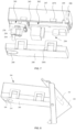
- the piping box 170 is disposed on a side of the first housing 100, and is located in the first subspace 161. There is an opening at a side of the piping box 170 away from the air outlet 120 (e.g., the rear side), the opening is provided toward the air duct, and a region among the opening, the indoor heat exchanger 130 and the first partition plate 150 forms an air inlet 171 of the piping box 170.
- the connecting plate 180 is provided on the side of the indoor heat exchanger 130 proximate to the air outlet 120 (e.g., the front side).
- the first housing 100 includes an inner bottom wall 190 and a front side wall.
- the front side wall is a side wall provided with the air outlet 120, and the connecting plate 180 is connected to the inner bottom wall 190 of the first housing 100 and the front side wall of the first housing 100, so as to separate the piping box 170 and the second air duct ( e.g., the downstream air duct), and the nano water ion generating apparatus 200 is disposed on the connecting plate 180.
- the portion (e.g., the top) of the indoor heat exchanger 130 away from the inner bottom wall 190 is inclined along a direction proximate to the air outlet 120.
- the connecting plate 180 is provided in an area formed among the indoor heat exchanger 130, the inner bottom wall 190 of the first housing 100, and the front side wall of the first housing 100.
- the inner bottom wall 190 may be an indoor water pan, and is configured to receive condensed water generated by the indoor heat exchanger 130.
- the inner bottom wall 190 is connected to a bottom wall of the indoor unit 10, and the inner bottom wall 190 of the first housing 100 is closer to the first accommodating space 101 than the bottom wall.
- the connecting plate 180 includes a mounting portion 182 (e.g., a mounting opening), the second housing 240 is inserted into the the mounting portion 182 and disposed at the mounting portion 182.
- a first portion of the second housing 240 is located in the piping box 170, and a second portion of the second housing 240 is located outside the piping box 170 (e.g., the air outlet 120 side).
- the second vent 280 is provided on a side wall of the first portion of the second housing 240, and the nano water ion release port 244 is provided on a side wall of the second portion of the second housing 240.
- the air in the piping box 170 directly flows into the inner cavity of the second housing 240 through the second vent 280, and then the air flows out from the nano water ion release port 244.
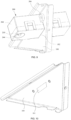
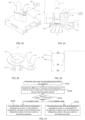
- FIGS. 11 to 13 illustrate three different installation orientations of the nano water ion generating apparatus 200 at the air outlet 120.
- the emitter electrode 210 is in an inclined state, which is tilted toward the air outlet 120 side.
- the emitter electrode 210 is in a horizontal state, which is facing the air outlet 120.
- the emitter electrode 210 is in a vertical state, whose emitter tip is facing downward. In this way, the installation manner of the emitter electrode 210 may be selected according to actual needs.
- any of the above installation manners of the nano water ion generating apparatus 200 may prevent the air from the air outlet 120 from blowing directly onto the emitter electrode 210, avoid affecting the air outlet temperature, and thus affect the condensation effect of the refrigeration portion 220 on the air.
- the space area of the piping box 170 is fully used, and the first vent 1701 is provided on a front side of the piping box 170.
- the piping box 170 serves as the role of branch and flow guide, part of the unheated air in an upstream air duct of the indoor heat exchanger 130 may be directed to the nano water ion generating apparatus 200 through the piping box 170.
- the air after heat exchange with the indoor heat exchanger 130 and the air directly flowing out from the piping box 170 will generate a temperature difference at the refrigeration portion 220, so that the water condensation capacity of the refrigeration portion 220 may be improved, and sufficient moisture for tip discharge may still be obtained to generate nano water ions and improve the air purification effect of the air conditioner 1000, even though the emitter electrode 210 is in the case of low humidity.
- the nano water ion generating apparatus 200 is disposed at the air outlet 120, and the emitter electrode 210 faces toward the air outlet 120, which effectively prevents the outlet air at the outlet 120 from blowing the emitter electrode 210 directly, so as to avoid affecting the outlet air temperature and affecting the air condensation of the refrigeration part 220.
- the nano water ion generating apparatus 200 is disposed on the connecting plate 180 for fixing a front end of the indoor heat exchanger 130.
- the connecting plate 180 also serves as a role of communicating the piping box 170 with the inner cavity of the nano water ion generating apparatus 200, as a result, the existing structure of the air conditioner 1000 may be fully used, and the structure is compact, which is also conducive to reducing the space occupied by the apparatus.
- the indoor unit 10 further includes an air pretreatment apparatus 300.
- the air pretreatment apparatus 300 will be described below.
- the air pretreatment apparatus 300 is provided in the air flow path that the air in the air duct flows to the nano water ion generating apparatus 200, and configured to preheat or precool the air flowing through the refrigeration portion 220, so as to improve the temperature difference of the surrounding air of the refrigeration portion 220, and improve the water condensation capacity of the refrigeration portion 220 , and thus sufficient moisture for tip discharge may still be obtained to generate nano water ions and improve the air purification effect of the air conditioner 1000, even though the emitter electrode 210 is in the case of low humidity.
- a flow guide channel 400 is branched out from the air duct, so that a part of the air in the air duct flows to the nano water ion generating apparatus 20.
- the air pretreatment apparatus 300 is configured to preheat or precool the air in the flow guide channel 400.
- An inlet of the flow guide channel 400 is located at an upstream of the indoor heat exchanger 130, and an outlet of the flow guide channel 400 is communicated to the second vent 280 of the second housing 240.
- the air pretreatment apparatus 300 is disposed on the air flow path between the inlet of the flow guide channel 400 and the refrigeration portion 220.
- a part of the air flowing into the air duct from the return air inlet 110 does not pass through the indoor heat exchanger 130, but flows into the flow guide channel 400, and then the part of air flows into the second accommodating space 202 of the second housing 240 through the second vent 280.
- the other part of the air flows out from the air outlet 120 after being heat exchanged by the indoor heat exchanger 130.
- it will flow through the air pretreatment apparatus 300, and be preheated or precooled by the air pretreatment apparatus 300, thereby increasing the air temperature difference at the refrigeration portion 220, and improving the capacity to generate condensed water of the refrigeration portion 220.
- the gas flow space formed in the piping box 170 may be the flow guide channel 400 mentioned above.
- the inlet of the flow guide channel 400 corresponds to the air inlet 171 of the piping box 170, and the outlet of the flow guide channel 400 corresponds to the first vent 1701 of the piping box 170.
- the air pretreatment apparatus 300 includes a refrigeration plate 310, a first heat exchange plate 320 and a second heat exchange plate 330.
- Two opposite sides of the refrigeration plate 310 along a thickness direction of the refrigeration plate 310 are the first side and the second side, respectively.
- the first heat exchange plate 320 is disposed on the first side of the refrigeration plate 310
- the second heat exchange plate 330 is disposed on the second side of the refrigeration plate 310.
- the first heat exchange plate 320 is located in the air flow channel between the inlet of the flow guide channel 400 and the refrigeration portion 220.
- the second heat exchange plate 330 is located outside the air flow channel between the inlet of the flow guide channel 400 and the refrigeration portion 220.
- the first heat exchange plate 320 may be a heat absorption plate
- the second heat exchange plate 330 may be a heat dissipation plate.
- the first heat exchange plate 320 may be the heat dissipation plate
- the second heat exchange plate 330 may be the heat absorption plate.
- the air pretreatment apparatus 300 turns on the preheating mode, and then it preheats the air flowing from the flow guide channel 400 toward the refrigeration portion 220.
- the first heat exchange plate 320 served as the heat sink plate
- the second heat exchange plate 330 served as the heat absorption plate.
- the air flowing through the air pretreatment apparatus 300 it is heated by the emitted heat of the first heat exchange plate 320, and the temperature rises, thereby increasing the temperature difference at the refrigeration portion 220, and improving the water condensation capacity of the refrigeration portion 220.
- the air pretreatment apparatus 300 turns on the precooling mode, and then it precools the air flowing from the flow guide channel 400 toward the refrigeration portion 220.
- the first heat exchange plate 320 served as the heat absorption plate
- the second heat exchange plate 330 served as the heat sink plate.
- the heat of the air is absorbed by the first heat exchange plate 320, and the temperature decreases, thereby increasing the temperature difference at the refrigeration portion 220, and improving the water condensation capacity of the refrigeration portion 220.
- the air pretreatment apparatus 300 includes a first ventilating gap 321 and a plurality of first heat exchange plates 320 arranged at intervals, and the first ventilating gap 321 is formed between two adjacent first heat exchange plates 320. The air flows through the first ventilating gap 321, so as to improve the heat exchange efficiency.
- the air pretreatment apparatus 300 includes a second ventilating gap 331 and a plurality of second heat exchange plates 330 arranged at intervals.
- the second ventilating gap 331 is formed between two adjacent second heat exchange plates 330, so as to improve the heat exchange efficiency.
- the air pretreatment apparatus 300 may be disposed in the piping box 170. Alternatively, the air pretreatment apparatus 300 may be disposed in the nano water ion generating apparatus 200.
- the air pretreatment apparatus 300 is disposed in the piping box 170.
- the connecting plate 180 includes a body, a third vent 181 and a mounting portion 182 (e.g., mounting hole).
- the third vent 181 penetrates through the body along a thickness direction thereof.
- the mounting portion 182 is disposed at the third vent 181.
- the first portion of the mounting portion 182 is located in the piping box 170, and the second portion of the mounting portion 182 is opposite to and communicated with the second vent 280.
- the inner cavity of the piping box 170 and the second accommodating space 202 of the second housing 240 may be communicated with each other.
- the refrigeration plate 310 is disposed on a portion of the mounting portion 182 located in the piping box 170, the first heat exchange plate 320 is located in the inner cavity of the mounting portion 182, and the second heat exchange plate 330 is located outside the mounting portion 182.
- FIGS. 18 to 20 the main difference between FIGS. 16 to 17 and FIGS. 18 to 20 lies in the arrangement position of the air pretreatment apparatus 300.
- the air pretreatment apparatus 300 is disposed in the nano water ion generating apparatus 200.
- the refrigeration plate 310 is disposed on the cover 248 of the second housing 240.
- the first heat exchange plate 320 is located in the second accommodating space 202 (e.g., the fourth subspace 242) of the second housing 240.
- the second heat exchange plate 330 is located outside the second housing 240.
- the air in the piping box 170 flows into the fourth subspace 242 of the second housing 240 through the inner cavity of the mounting portion 182, and then continues to flow to the third subspace 241.
- the air is in contact with the first heat exchange plate 320, and flows through the first ventilating gap 321, so as to achieve preheating or precooling of the air.
- control method includes steps S101 to S105.
- Step S102 Calculate the difference ⁇ T between the first temperature T11 of the air at the air outlet and the second temperature T12 of the air in the flow guide channel.
- the flow guide channel refers to the inner cavity of the piping box 170.
- Step S103 Whether ⁇ T is positive or negative is determined. If ⁇ T is greater than 0, step S104 is performed; if ⁇ T is less than 0, step S105 is performed.
- Step S104 If it is determined that ⁇ T is greater than 0, the precooling mode of the air pretreatment apparatus 300 is turned on, which performs temperature decrease on the air flowing to the refrigeration portion 220 in the nano water ion generating apparatus 200, so as to increase the temperature difference.
- the air pretreatment apparatus 300 precools the air flowing through the refrigeration portion 220.
- the air pretreatment apparatus 300 preheats the air flowing through the refrigeration portion 220.
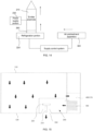
- control system e.g., a controller
- the control system of the air conditioner 1000 may also directly read the cooling or heating control command of the air conditioner 1000, so as to determine whether the air conditioner 1000 is in the cooling or heating mode directly, thereby further controlling the air pretreatment apparatus 300 to precool or preheat the air flowing through the refrigeration portion 220.
- the air conditioner 1000 further includes a humidity sensor, the humidity sensor is configured to detect the relative humidity of the air at the air outlet 120.
- the controller is coupled to the humidity sensor and the air pretreatment apparatus 300, respectively, and the controller is configured to precool or preheat the air passing through the air pretreatment apparatus 300 based on the relative humidity feedback from the humidity sensor.
- the controller obtains the relative humidity Rh of the air at the air outlet 120, and adjusts the switch of the air pretreatment apparatus 300 according to the relative humidity Rh.
- the controller switches between the precooling mode and the preheating mode of the air pretreatment apparatus 300, according to the difference ⁇ T between the first temperature T11 of the air at the air outlet 120 and the second temperature T12 of the air in the piping box 170.
- the controller adjusts the working power of the precooling or preheating mode of the air pretreatment apparatus 300 to adjust the cooling capacity or heating capacity, and precools or preheats the air flowing through the air pretreatment apparatus 300, so as to increase the temperature difference at the refrigeration portion 220, and improve the water condensation capacity of the refrigeration portion 220.
- the working mode of the air pretreatment apparatus 300 (e.g., precooling or preheating the air flowing through it) is also varies due to the control of the controller.
- the working mode of the air pretreatment apparatus 300 By adjusting the working mode of the air pretreatment apparatus 300, the temperature difference at the refrigeration portion 220 may be adjusted, thereby the water condensation capacity of the refrigeration portion 220 may be improved.
- the air pretreatment apparatus 300 is turned off, and the moisture may be condensed from the air by the cooling capacity of the refrigeration portion 220.
- the relative humidity is less than the preset relative humidity (i.e. Rh ⁇ Rh1), it indicates that the humidity is relatively low. If the air conditioner 1000 is in the cooling mode, the preheating mode of the air pretreatment apparatus 300 is turned on; if the air conditioner 1000 is in the heating mode, then the precooling mode of the air pretreatment apparatus 300 is turned on.
- the heating capacity or the cooling capacity of the air pretreatment apparatus 300 is inversely proportional to the relative humidity Rh.
- the second relative humidity is less than the first relative humidity (i.e. Rh2 ⁇ Rh1
- the first relative humidity corresponds to the above-mentioned preset relative humidity
- the air pretreatment apparatus 300 in a case where the difference ⁇ T between the first temperature T11 of the air at the air outlet 120 and the second temperature T12 of the air in the flow guide channel 400 is less than a first preset threshold T10, it indicates that the temperature difference is relatively small, in this case, the air pretreatment apparatus 300 is turned on, and the air flowing from the flow guide channel 400 to the refrigeration portion 220 needs to be pretreated.
- the difference ⁇ T between the first temperature T11 of the air at the air outlet 120 and the second temperature T12 of the air in the flow guide channel 400 is greater than the second preset threshold T20, it indicates that the temperature difference is relatively large, in this case, the air pretreatment apparatus 300 is turned off, and the moisture may be condensed from the air by the cooling capacity of the refrigeration portion 220.
- the heating capacity or the cooling capacity of the air pretreatment apparatus 300 is inversely proportional to the difference ⁇ T between the first temperature T11 of the air at the air outlet 120 and the second temperature T12 of the air in the flow guide channel 400.
- T1 is less than T2 (T1 ⁇ T2, T is a positive value).
- ⁇ T is greater than or equal to 0 and less than or equal to T1 (i.e., 0 ⁇ T ⁇ T1)
- the precooling mode of the air pretreatment apparatus 300 is turned on, and the cooling capacity is Q12.
- ⁇ T is less than or equal to -T2 (i.e., ⁇ T ⁇ -T2)
- the air pretreatment apparatus 300 is turned off.
- ⁇ T is greater than or equal to T2 and less than or equal to -T1 (i.e., -T2 ⁇ T ⁇ -T1)
- the preheating mode of the air pretreatment apparatus 300 is turned on, and the heating capacity is Q21.
- ⁇ T is greater than or equal to -T1 and less than or equal to 0 (i.e., -T1 ⁇ T ⁇ 0)
- the preheating mode of the air pretreatment apparatus 300 is turned on, and the heating capacity is Q22.
- heating capacity Q22 is greater than the heating capacity Q21 (i.e., Q22>Q21).
- ⁇ T is greater than or equal to T1 and less than or equal to T2 (i.e., T1 ⁇ T ⁇ T2)
- the precooling mode of the air pretreatment apparatus 300 is turned on, and the cooling capacity is Q31.
- ⁇ T is greater than or equal to 0 and less than or equal to T1 (i.e., 0 ⁇ T ⁇ T1)
- the precooling mode of the air pretreatment apparatus 300 is turned on, and the cooling capacity is Q32.
- ⁇ T is less than or equal to -T2 (i.e., ⁇ T ⁇ -T2)
- the air pretreatment apparatus 300 is turned off.
- ⁇ T is greater than or equal to -T2 and less than or equal to -T1 (i.e., -T2 ⁇ T ⁇ -T1)
- the preheating mode of the air pretreatment apparatus 300 is turned on, and the heating capacity is Q41.
- ⁇ T is greater than or equal to -T1 and less than or equal to 0 (i.e., -T1 ⁇ T ⁇ 0)
- the preheating mode of the air pretreatment apparatus 300 is turned on, and the heating capacity is Q42.
- the heating capacity Q42 is greater than the heating capacity Q41
- the heating capacity Q41 is greater than the heating capacity Q22
- the heating capacity Q22 is greater than the heating capacity Q21 (i.e., Q42>Q41>Q22>Q21).
- the air pretreatment apparatus 300 may not only prevent the excessive water condensation of the refrigeration portion 220, but also improve the water condensation capacity of the refrigeration portion 220 under dry conditions.
- the nano water ion generating apparatus 200 in addition to the emitter electrode 210, the conductive portion 250 (e.g., a metal clamping portion) and a electrode fixing base 270, the nano water ion generating apparatus 200 further includes a wiring bolt 3.
- the elastic clamping arm 22A is located in the first connecting hole 41.
- the fixed mounting arm 24A is connected to the clamping portion body and extends in a direction away from the clamping portion body (or the electrode mounting hole 21A).
- the fixed mounting arm 24A is connected to the second connecting hole 42 through the wiring bolt 3.
- the elastic clamping arm 22A extends substantially in a direction parallel to a center line of the electrode mounting hole 21A, and the fixed mounting arm 24A extends in a radial direction of the electrode mounting hole 21A.
- the conductive portion 250 further includes a mounting chamfer 23A located between the clamping portion body and the elastic clamping arm 22A.
- the installation chamfer 23A may not only guide the assembly of the emitter electrode 210, but also achieve the protection of the emitter electrode 210.
- the emitter electrode 210 has the ability to absorb and conduct water, and is a porous columnar electrode mainly formed by solidifying conductive fiber bundles through a curing agent and carbonizing under high temperature conditions. In an environment with high air humidity, the emitter electrode 210 may directly absorb moisture in the air.
- the nano water ion generating apparatus 200 is capable of achieving the air purification, disinfection and sterilization.
- the air conditioner 1000 with the nano water ion generating apparatus 200 also has a good air purification effect.
- the conductive portion 250 includes two, three or more elastic clamping arms 22A. In this way, it is conducive to improving the reliability of the conductive portion 250.
- an outer diameter of the emitter electrode 210 is D1.
- the elastic clamping arm 22A includes a first segment 221 and a second segment 222 that are connected with each other.
- the second segment 222 is further away from the clamping portion body than the first segment 221, and a portion of the second segment 222 is configured to contract in a direction proximate to a center line of the electrode fixing hole 21A.
- the first segment 221 is a straight segment
- the second segment 222 is a curved segment.
- the first segment 221 forms an inner diameter D2 around the electrode fixing hole 21A
- the second segment 222 forms an inner diameter D3 (e.g., a minimum inner diameter) around the electrode fixing hole 21A.
- D1, D2 and D3 satisfy a relationship that D2 is greater than D1, and D1 is greater than D3 (i.e., D2>D1>D3).
- a bottom end of the emitter electrode 210 is inserted into the electrode fixing hole 21A from the first segment 221, and the outer side wall of the emitter electrode 210 is in contact with the portion of the second segment 222.
- the bottom end of the emitter electrode 210 is inserted into the conductive portion 250 from the electrode mounting hole 21A, and is elastically fixed by abutting the elastic clamping arm 22A.
- the installation chamfer 23A may prevent the collision of the electrode material and the fiber damage caused by the insertion of the emitter electrode 210 into the conductive portion 250.
- This manner of fixing the electrode allows the emitter electrode 210 to be plug-and-play, and is convenient and fast. In this way, it may implement rapid assembly and replacement of the emitter electrode 210, and solve a problem of poor conductive connection of water absorbing electrode materials.
- the elastic clamping arm 22A of the conductive portion 250 extends into the first connecting hole 41.
- the fixed installation arm 24A includes a fixing hole 25, and the wiring bolt 3 is inserted into the fixing hole 25.
- the wiring bolt 3 plays a role in fixing the conductive portion 250.
- the high voltage wire 31 (referring to FIG. 23 ) is also fixed to the electrode fixing base 270 through the wiring bolt 3.
- an end of the emitter electrode 210 is coupled to the power supply portion 230 through a high voltage line 31, thus facilitating the electrical connection between the power supply portion 230 and the emitter electrode 210.
- the electrode fixing base 270 further includes a first boss portion 43, the first boss portion 43 is located at the bottom of the first connecting hole 41, and the bottom end of the emitter electrode 210 is in contact with the first boss portion 43.
- the first boss portion 43 is configured to control a height of a water absorbing portion of the emitter electrode 210 and play a role in positioning the emitter electrode 210.
- a distance between the first boss portion 43 and the fixed mounting arm 24A is H1
- a height of the emitter electrode 210 is H2.
- H1 and H2 satisfy a relationship that H1 is less than H2 (i.e., H1 ⁇ H2). In this way, the top of the emitter electrode 210 is higher than the upper surface of the electrode fixing base 270, the emitter electrode 210 exposed in the air may directly absorb moisture in the air.
- the generation process of the nano water ions in the nano water ion generating apparatus 200 includes that the wiring bolt 3 is connected to the power supply portion 230, the electrode fixing base 270 is made of insulating material (e.g., polypropylene), and the negative high voltage electricity output by the power supply portion 230 is directly transmitted to the conductive portion 250 through the wiring bolt 3, and then transmitted to the emitter electrode 210 through the elastic clamping arm 22A of the conductive portion 250.
- the negative high voltage is applied to the emitter electrode 210, there are countless micropores on the surface of the water absorbing material, and countless nano water ion release points are formed due to the action of the high voltage electric field.
- the negative high voltage provided by the power supply portion 230 generates corona discharge, thereby ionizing the water to generate the negatively charged nano water ions and sprayed the nano water ions into the air.
- the nano water ion generating apparatus 200 in some embodiments of the present disclosure directly uses the ground or surrounding grounded objects as the counter electrode of the emitter electrode 210. There is no need to provide an additional counter electrode. Therefore, the generated negatively charged nano water ions will not be absorbed by the counter electrode.
- the nano water ion generating apparatus 200 does not include the cooling portion 220. In some other embodiments, the nano water ion generating apparatus 200 includes the cooling portion 220. For example, when it is necessary to provide condensed water for the emitter electrode 210, the nano water ion generating apparatus 200 including the cooling portion 220 may be selected. When it is not necessary to provide condensed water for the emitter electrode 210, the nano water ion generating apparatus 200 which does not include the cooling portion 220 may be selected. Hereinafter, the nano water ion generating apparatus 200 including the cooling portion 220 will be introduced.
- the electrode fixing base 270 further includes a second boss portion 44 and an accommodating cavity 43A communicated to the first connecting hole 41.
- the cooling portion 220 is located in the accommodating cavity 43A at the bottom of the electrode fixing base 270, and a portion of the cooling portion 220 abuts against the second boss portion 44.
- the cooling portion 220 includes a ceramic insulating sheet 51, a PN junction 52, a metal conductor sheet 53, and a heat sink 54.
- the ceramic insulating sheet 51 is connected to a cold end of the PN junction 52, therefore, the condensed water will be generated in the water storage gap between the emitter electrode 210 and the cooling portion 220.
- the ceramic insulating sheet 51 is located on a surface (e.g., an upper surface) of the PN junction 52 proximate to the first boss portion 43 to insulate the emitter electrode 210 from the PN junction 52, so as to avoid the negative high voltage transmitted to the emitter electrode 210 from affecting semiconductor cooling.
- a surface (e.g., a lower surface) of the PN junction 52 away from the first boss portion 43 is connected to the metal conductor sheet 53, and the metal conductor sheet 53 is connected to a power source to form an electrical circuit with the PN junction 52.
- the heat sink 54 is located at a side (e.g., the bottom) of the metal conductor sheet 53 away from the PN junction 52.
- the metal conductor sheet 53 may abut against the second boss portion 44.
- thermocouple formed by connecting the N-type semiconductor material and the P-type semiconductor material in the cooling portion 220
- heat transfer will occur between the two ends of the PN junction 52, and the heat will be transferred from an end to another end of the PN junction 52, thereby generating a temperature difference to form a cold end and a hot end.
- the condensed water will be generated.
- the nano water ion generating apparatus 200 in some embodiments of the present disclosure controls a distance between the emitter electrode 210 and the ceramic insulating sheet 51 by controlling a distance between the first boss portion 43 and the second boss portion 44 (e.g., a distance in a height direction of the emitter electrode 210), and there is a water storage gap in a range from 0.2 mm to 0.8 mm (e.g., 0.2 mm, 0.4 mm, 0.6 mm or 0.8 mm) between the emitter electrode 210 and the ceramic insulating sheet 51.
- the ceramic insulating sheet 51 is located at a cooling surface on the upper surface of the PN junction 52. In a case where the condensed water 6 is generated on the cooling portion 220, the condensed water 6 is in contact with the emitter electrode 210 and is absorbed by the emitter electrode 210, thereby continuously providing moisture to the emitter electrode 210.
- the emitter electrode 210 may not only absorb moisture directly from the air, but also utilize the condensed water provided by the cooling portion 220, thereby fully ensuring the water supply of the emitter electrode 210, so that the nano water ion generating apparatus 200 may stably generate the nano water ions with negative oxygen ions.
- the electrode fixing base 270 includes a fourth vent communicated with the accommodating cavity 43A.
- the fourth vent may circulate the air between the cooling portion 220 and the electrode fixing base 270, so that the cooling portion 220 condenses water in the air.
- the emitter electrode 210 in an environment with high air humidity, directly absorbs moisture in the air to supply water to the emitter electrode 210.
- the emitter electrode 210 uses the surrounding ground or grounded objects as the counter electrode and directly ionizes water by using the negative high voltage, so as to generated the nano water ions containing the negative oxygen ions, thereby improving the air purification capability.
Landscapes
- Engineering & Computer Science (AREA)
- Mechanical Engineering (AREA)
- General Engineering & Computer Science (AREA)
- Chemical & Material Sciences (AREA)
- Combustion & Propulsion (AREA)
- Physics & Mathematics (AREA)
- Thermal Sciences (AREA)
- Air Filters, Heat-Exchange Apparatuses, And Housings Of Air-Conditioning Units (AREA)
- Other Air-Conditioning Systems (AREA)
Applications Claiming Priority (5)
| Application Number | Priority Date | Filing Date | Title |
|---|---|---|---|
| CN202210324187.5A CN114893828B (zh) | 2022-03-30 | 2022-03-30 | 一种空调器 |
| CN202220715340.2U CN217082726U (zh) | 2022-03-30 | 2022-03-30 | 一种空调器 |
| CN202220731725.8U CN217464666U (zh) | 2022-03-31 | 2022-03-31 | 一种负氧水离子发生装置和空调器 |
| CN202220733579.2U CN217464667U (zh) | 2022-03-31 | 2022-03-31 | 一种负氧水离子发生装置和空调器 |
| PCT/CN2022/136313 WO2023185063A1 (zh) | 2022-03-30 | 2022-12-02 | 空调器 |
Publications (2)
| Publication Number | Publication Date |
|---|---|
| EP4498005A1 true EP4498005A1 (de) | 2025-01-29 |
| EP4498005A4 EP4498005A4 (de) | 2026-03-25 |
Family
ID=88198930
Family Applications (1)
| Application Number | Title | Priority Date | Filing Date |
|---|---|---|---|
| EP22934881.8A Pending EP4498005A4 (de) | 2022-03-30 | 2022-12-02 | Klimaanlage |
Country Status (2)
| Country | Link |
|---|---|
| EP (1) | EP4498005A4 (de) |
| WO (1) | WO2023185063A1 (de) |
Families Citing this family (1)
| Publication number | Priority date | Publication date | Assignee | Title |
|---|---|---|---|---|
| CN120292706A (zh) * | 2024-01-11 | 2025-07-11 | 合肥美的暖通设备有限公司 | 风道组件和空气调节装置 |
Family Cites Families (8)
| Publication number | Priority date | Publication date | Assignee | Title |
|---|---|---|---|---|
| JP2002310531A (ja) * | 2001-04-05 | 2002-10-23 | Ihara Takeo | 電気装置の節電システム |
| JP2009216286A (ja) * | 2008-03-10 | 2009-09-24 | Panasonic Corp | 空気調和機 |
| JP5256828B2 (ja) * | 2008-04-07 | 2013-08-07 | パナソニック株式会社 | 換気空調装置 |
| CN203404884U (zh) * | 2013-08-02 | 2014-01-22 | 广东美的制冷设备有限公司 | 空调 |
| CN107894028B (zh) * | 2017-11-14 | 2020-03-13 | 青岛海信日立空调系统有限公司 | 空调器及其控制方法、多联机空调系统 |
| CN113719906A (zh) * | 2021-09-26 | 2021-11-30 | 青岛海信日立空调系统有限公司 | 一种空调器 |
| CN114893828B (zh) * | 2022-03-30 | 2023-08-18 | 青岛海信日立空调系统有限公司 | 一种空调器 |
| CN217082726U (zh) * | 2022-03-30 | 2022-07-29 | 青岛海信日立空调系统有限公司 | 一种空调器 |
-
2022
- 2022-12-02 EP EP22934881.8A patent/EP4498005A4/de active Pending
- 2022-12-02 WO PCT/CN2022/136313 patent/WO2023185063A1/zh not_active Ceased
Also Published As
| Publication number | Publication date |
|---|---|
| EP4498005A4 (de) | 2026-03-25 |
| WO2023185063A1 (zh) | 2023-10-05 |
Similar Documents
| Publication | Publication Date | Title |
|---|---|---|
| CN114893828B (zh) | 一种空调器 | |
| CN217082727U (zh) | 一种空调器 | |
| CN110748974B (zh) | 空调系统及空调系统控制方法 | |
| EP4498005A1 (de) | Klimaanlage | |
| CN217082726U (zh) | 一种空调器 | |
| CN113432217B (zh) | 一种空气净化装置及空调器 | |
| WO2023226977A1 (zh) | 换热设备及换热系统 | |
| JP5777589B2 (ja) | 環境試験装置及び空調システムの制御方法 | |
| US20240288188A1 (en) | Air conditioner, control system and control method of air conditioner | |
| CN115751470B (zh) | 一种空气净化模块及空调器 | |
| US12259145B2 (en) | Air conditioner | |
| CN208368958U (zh) | 一种智能除湿装置 | |
| JP7275385B2 (ja) | 圧縮機 | |
| KR100896805B1 (ko) | 항온항습 기능을 갖는 증기식 공기조화기 | |
| CN110035637B (zh) | 一种数据中心用水冷加除湿一体机 | |
| CN222964072U (zh) | 空气调节装置 | |
| CN220728456U (zh) | 一种空气处理设备 | |
| CN218583335U (zh) | 室内机及空调器 | |
| CN217636250U (zh) | 一种空调器 | |
| CN118361872B (zh) | 热泵系统的控制方法及装置、介质、热泵系统和储能设备 | |
| CN221728790U (zh) | 一种数据中心的恒温除湿装置 | |
| CN223228513U (zh) | 空调器 | |
| CN218820670U (zh) | 一种空调室内机 | |
| CN221409571U (zh) | 一种顶置式空气调节装置 | |
| CN101307934A (zh) | 空气热源热泵式空调机 |
Legal Events
| Date | Code | Title | Description |
|---|---|---|---|
| STAA | Information on the status of an ep patent application or granted ep patent |
Free format text: STATUS: THE INTERNATIONAL PUBLICATION HAS BEEN MADE |
|
| PUAI | Public reference made under article 153(3) epc to a published international application that has entered the european phase |
Free format text: ORIGINAL CODE: 0009012 |
|
| STAA | Information on the status of an ep patent application or granted ep patent |
Free format text: STATUS: REQUEST FOR EXAMINATION WAS MADE |
|
| 17P | Request for examination filed |
Effective date: 20240517 |
|
| AK | Designated contracting states |
Kind code of ref document: A1 Designated state(s): AL AT BE BG CH CY CZ DE DK EE ES FI FR GB GR HR HU IE IS IT LI LT LU LV MC ME MK MT NL NO PL PT RO RS SE SI SK SM TR |
|
| DAV | Request for validation of the european patent (deleted) | ||
| DAX | Request for extension of the european patent (deleted) | ||
| A4 | Supplementary search report drawn up and despatched |
Effective date: 20260219 |
|
| RIC1 | Information provided on ipc code assigned before grant |
Ipc: F24F 1/0076 20190101AFI20260213BHEP Ipc: F24F 8/30 20210101ALI20260213BHEP Ipc: F24F 13/22 20060101ALI20260213BHEP Ipc: F25B 21/02 20060101ALI20260213BHEP Ipc: F24F 1/0047 20190101ALI20260213BHEP Ipc: F25B 13/00 20060101ALI20260213BHEP Ipc: F24F 1/0071 20190101ALI20260213BHEP |