EP4497706A1 - Stapelvorrichtung - Google Patents
Stapelvorrichtung Download PDFInfo
- Publication number
- EP4497706A1 EP4497706A1 EP23803329.4A EP23803329A EP4497706A1 EP 4497706 A1 EP4497706 A1 EP 4497706A1 EP 23803329 A EP23803329 A EP 23803329A EP 4497706 A1 EP4497706 A1 EP 4497706A1
- Authority
- EP
- European Patent Office
- Prior art keywords
- space
- cranes
- stacker crane
- traveling
- stocker
- Prior art date
- Legal status (The legal status is an assumption and is not a legal conclusion. Google has not performed a legal analysis and makes no representation as to the accuracy of the status listed.)
- Pending
Links
Images


Classifications
-
- B—PERFORMING OPERATIONS; TRANSPORTING
- B65—CONVEYING; PACKING; STORING; HANDLING THIN OR FILAMENTARY MATERIAL
- B65G—TRANSPORT OR STORAGE DEVICES, e.g. CONVEYORS FOR LOADING OR TIPPING, SHOP CONVEYOR SYSTEMS OR PNEUMATIC TUBE CONVEYORS
- B65G1/00—Storing articles, individually or in orderly arrangement, in warehouses or magazines
- B65G1/02—Storage devices
- B65G1/04—Storage devices mechanical
- B65G1/0407—Storage devices mechanical using stacker cranes
- B65G1/0421—Storage devices mechanical using stacker cranes with control for stacker crane operations
-
- B—PERFORMING OPERATIONS; TRANSPORTING
- B65—CONVEYING; PACKING; STORING; HANDLING THIN OR FILAMENTARY MATERIAL
- B65G—TRANSPORT OR STORAGE DEVICES, e.g. CONVEYORS FOR LOADING OR TIPPING, SHOP CONVEYOR SYSTEMS OR PNEUMATIC TUBE CONVEYORS
- B65G1/00—Storing articles, individually or in orderly arrangement, in warehouses or magazines
- B65G1/02—Storage devices
- B65G1/04—Storage devices mechanical
- B65G1/0407—Storage devices mechanical using stacker cranes
- B65G1/0428—Transfer means for the stacker crane between the alleys
-
- B—PERFORMING OPERATIONS; TRANSPORTING
- B66—HOISTING; LIFTING; HAULING
- B66F—HOISTING, LIFTING, HAULING OR PUSHING, NOT OTHERWISE PROVIDED FOR, e.g. DEVICES WHICH APPLY A LIFTING OR PUSHING FORCE DIRECTLY TO THE SURFACE OF A LOAD
- B66F9/00—Devices for lifting or lowering bulky or heavy goods for loading or unloading purposes
- B66F9/06—Devices for lifting or lowering bulky or heavy goods for loading or unloading purposes movable, with their loads, on wheels or the like, e.g. fork-lift trucks
- B66F9/063—Automatically guided
-
- B—PERFORMING OPERATIONS; TRANSPORTING
- B66—HOISTING; LIFTING; HAULING
- B66F—HOISTING, LIFTING, HAULING OR PUSHING, NOT OTHERWISE PROVIDED FOR, e.g. DEVICES WHICH APPLY A LIFTING OR PUSHING FORCE DIRECTLY TO THE SURFACE OF A LOAD
- B66F9/00—Devices for lifting or lowering bulky or heavy goods for loading or unloading purposes
- B66F9/06—Devices for lifting or lowering bulky or heavy goods for loading or unloading purposes movable, with their loads, on wheels or the like, e.g. fork-lift trucks
- B66F9/07—Floor-to-roof stacking devices, e.g. "stacker cranes", "retrievers"
- B66F9/072—Travelling gear therefor
Definitions
- One aspect of the invention relates to a stocker.
- Patent Document 1 discloses an automatic warehouse in which two stockers each including two cranes and two racks disposed so as to sandwich the cranes along a traveling direction of the two cranes are arranged in the traveling direction of the two cranes.
- the crane included in this stocker includes a mast extending in a vertical direction, and a transfer unit configured to transfer articles to the racks is provided so as to be capable of being raised and lowered along one of a pair of surfaces in the traveling direction constituted on the mast.
- Patent Document 1 Japanese Unexamined Patent Publication No. 2015-9953
- an object of one aspect of the present invention is to provide a stocker including a crane having a transfer unit provided so as to be capable of being raised and lowered along one of the pair of surfaces of a mast orthogonal to a traveling direction, the stocker being capable of increasing the number of articles that can be housed in the stocker.
- a stocker includes: two cranes configured to travel on a rail extending in one direction; racks being disposed so as to extend along and sandwich the rail, an article being placed in and removed from the racks by the two cranes; a first space constituent part constituting a first space housing the two cranes and the racks; and a controller configured to control the two cranes, each of the two cranes including a mast having a pair of surfaces orthogonal to a traveling direction of the two cranes and a transfer unit provided so as to be capable of being raised and lowered along one of the pair of surfaces and configured to transfer the article to and from the racks, the two cranes being disposed such that each faces a direction opposite to a direction in which the one of the pair of surfaces on which the transfer unit is provided so as to be capable of being raised and lowered face each other in the traveling direction, the first space being provided with an entry area that the two cranes mutually enter, and the controller controlling traveling of the two cranes such that the two cranes do not collide with each
- the two cranes are provided in the first space constituted by the first space constituent part and are disposed such that each faces a direction opposite to a direction in which the one of the pair of surfaces on which the respective transfer units of the two cranes are provided so as to be capable of being raised and lowered face each other in the traveling direction.
- the article is transferred to a rack portion interfering with the mast of one crane at one end of the first space (the stocker) in the traveling direction by the other crane, and the article is transferred to a rack portion interfering with the mast of the other crane at the other end of the first space in the traveling direction by the one crane.
- rack portions can also be disposed at the ends of the first space in the travel direction, and the article can be transferred to the rack portions as well.
- the first space is provided with the entry area that the two cranes mutually enter, and thus rack portions from which the article can be transferred to only either one of the two cranes will not be constituted.
- the entry area may be provided at a central portion of the first space in the traveling direction.
- the transfer unit may be provided so as to protrude from the one of the pair of surfaces of the mast in the traveling direction. This configuration can make the cranes compact in size in a width direction orthogonal to the travel direction.
- the controller may cause the other of the two cranes to travel at a speed being a second speed set as an upper limit lower than the first speed in the entire area of the first space. This enables the crane to travel safely to the operator, although the first space cannot be completely isolated from the operator.
- One aspect of the present invention can provide a stocker including a crane having a transfer unit provided so as to be raised and lowered along one of the pair surfaces of a mast orthogonal to a traveling direction, the stocker being capable of increasing the number of articles that can be housed in the stocker.
- the article A is, for example, a container such as a front-opening unified pod (FOUP) housing wafers to be processed in semiconductor manufacturing apparatuses or liquid crystal manufacturing apparatuses or a reticle pod housing reticles to be used in semiconductor manufacturing apparatuses or liquid crystal manufacturing apparatuses.
- FOUP front-opening unified pod
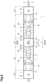
- the embodiment may be described with a traveling direction D of the first stacker crane 7A and the second stacker crane 7B as a right and left direction, with a width direction W orthogonal to the traveling direction D as a front and rear direction, and with a vertical direction as an up and down direction.
- the stocker main body 3 constitutes a first space S1 extending in one direction.
- the stocker main body 3 includes a frame and a panel, which are not illustrated.
- the stocker main body 3 constitutes the first space S1 capable of housing part of a traveling rail 31 on which the first stacker crane 7A and the second stacker crane 7B travel, part of an auxiliary rail 32 disposed so as to face the traveling rail 31 in the vertical direction, the two first stacker crane 7A and second stacker crane 7B traveling along the traveling rail 31 and the auxiliary rail 32, and a first rack 4A and a second rack 4B disposed along an extension direction of the traveling rail 31 and the auxiliary rail 32.
- the first space S1 constituted by the stocker main body 3 includes a traveling area S11 through which the first stacker crane 7A and the second stacker crane 7B travel and rack areas S12 disposed so as to sandwich the traveling area S11.
- stocker reserves (second space constituting parts) 3A, 3A constituting second spaces S2 capable of housing the first stacker crane 7A or the second stacker crane 7B having exited from the first space S1 are disposed.
- the second space S2 is a space surrounded by part of the stocker main body 3 and the stocker reserve 3A.
- the stocker reserve 3A includes a frame and a panel, which are not illustrated.
- the second space S2 houses the traveling rail 31 and the auxiliary rail 32 extending from the first space S1.
- the thus constituted second space S2 on the right side constitutes a first maintenance area A11 in which the first stacker crane 7A is maintained.
- the second space S2 on the left side constitutes a second maintenance area A12 in which the second stacker crane 7B is maintained.
- the stocker main body 3 includes a door 35, a first shutter (an opening and closing part) 36, and a second shutter (the opening and closing part) 37.
- the door 35 is provided to allow an operator to enter and exit from the first space S1.
- the door 35 is provided at the center of a front surface of the stocker main body 3 in the right and left direction.
- the first shutter 36 is provided to allow the first stacker crane 7A to enter and exit from the first space S1 from a right end of the first space S1 in the traveling direction D.
- the first shutter 36 is provided at a right end of the stocker main body 3.
- the second shutter 37 is provided to allow the second stacker crane 7B to enter and exit from the first space S1 from a left end of the first space S1 in the traveling direction D.
- the second shutter 37 is provided at a left end of the stocker main body 3.
- the second shutter 37 can switch states between an open state, in which the second stacker crane 7B can come and go between the first space S1 and the second space S2, and a closed state, in which the second stacker crane 7B cannot come and go between the first space S1 and the second space S2.
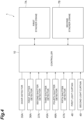
- the door 35, the first shutter 36, and the second shutter 37 are provided with a door detector 35A, a first shutter detector 36A, and a second shutter detector 37A, respectively, configured to detect the state of opening and closing.
- Examples of the door detector 35A, the first shutter detector 36A, and the second shutter detector 37A include contact sensors and optical sensors. As illustrated in FIG. 4 , detection results of the state of opening and closing by the door detector 35A, the first shutter detector 36A, and the second shutter detector 37A are acquired by the controller 10.
- Each of the first rack 4A and the second rack 4B includes a plurality of loading portions 41 each of which is loaded with one article A.
- the loading portions 41 are arranged in the vertical direction and a horizontal direction.
- the first rack 4A and the second rack 4B are disposed along the traveling area S11.
- the first rack 4A and the second rack 4B are disposed such that each face in the width direction orthogonal to the extension direction of the traveling area S11 (the traveling rail 31 and the auxiliary rail 32) and the vertical direction.
- Each of the first rack 4A and the second rack 4B includes the loading portions 41 in almost all of the first space S1 except for a lower area S16 of an entry area A3, which is described in detail below.
- each of the first stacker crane 7A and the second stacker crane 7B includes a traveling part 71, the mast 72, a lifting platform 73, the transfer unit 75, an auxiliary traveling part 77, and a sensor 79 (refer to FIG. 1 ).
- the traveling part 71 mainly includes a motor 71A for traveling and a motor 71B for lifting and lowering.
- the traveling part 71 travels along the traveling rail 31.
- the traveling part 71 includes driving wheels for traveling rolling along an upper surface of the traveling rail 31.
- the motor 71A for traveling is a driving source for the driving wheels for traveling.
- the motor 71B for lifting and lowering is a driving source for the lifting platform 73.
- the mast 72 is erected in the vertical direction at the top of the traveling part 71.
- the mast 72 has a pair of surfaces (a first surface 72a and a second surface 72b) orthogonal to the traveling direction D of the crane.
- the first surface 72a of the first stacker crane 7A and the first surface 72a of the second stacker crane 7B are faces on which the lifting platform 73 is provided so as to be capable of being raised and lowered.
- the lifting platform 73 (the transfer unit 75) of the first stacker crane 7A is provided so as to be raised and lowered along the first surface 72a
- the lifting platform 73 (the transfer unit 75) of the second stacker crane 7B is also provided so as to be capable of being raised and lowered along the first surface 72a.
- the first stacker crane 7A and the second stacker crane 7B are disposed such that each faces a direction opposite to a direction in which the first surfaces 72a, 72a on which the lifting platforms 73 (the transfer units 75) are provided so as to be capable of being raised and lowered face each other in the traveling direction D (so as to face away from each other).
- the first stacker crane 7A and the second stacker crane 7B are disposed such that the second surfaces 72b, 72b face each other.
- the first stacker crane 7A and the second stacker crane 7B may be provided with a shock absorber, for example, on the second surface 72b of at least one of the first stacker crane 7A and the second stacker crane 7B. This can prevent the whole or part of the first stacker crane 7A and the second stacker crane 7B from being damaged even if the first stacker crane 7A and the second stacker crane 7B collide with each other.
- first traveling area A1 is set so that the article A can be transferred to and from the loading portions 41 disposed in a range R1 illustrated in FIG. 1 .
- second traveling area A2 is set so that the article A can be transferred to and from the loading portions 41 disposed in a range R2 illustrated in FIG. 1 .
- the entry area A3 that the two first stacker crane 7A and second stacker crane 7B mutually enter is set.
- the entry area A3 is provided at a central portion of the first space S1 in the travel direction D.
- the controller 10 is provided so as to be able to switch among the normal mode, in which both the first stacker crane 7A and the second stacker crane 7B are operated, a first separation mode, in which the operation of one of the first stacker crane 7A and the second stacker crane 7B is stopped in the first space S1, and a second separation mode, in which the operation of one of the first stacker crane 7A and the second stacker crane 7B is stopped in the second space S2.
- the switching among the modes can be switched by the operator by means of an operating unit or the like, not illustrated.
- the controller 10 controls the traveling of the first stacker crane 7A such that the first stacker crane 7A travels only through the first traveling area A1 and the entry area A3 (the first stacker crane 7A does not advance into the second traveling area A2) and controls the traveling of the second stacker crane 7B such that the second stacker crane 7B travels only through the second traveling area A2 and the entry area A3 (the second stacker crane 7B does not advance into the first traveling area A1).
- the controller 10 controls the traveling of the first stacker crane 7A and the second stacker crane 7B such that the first stacker crane 7A and the second stacker crane 7B do not collide with each other.
- the controller 10 performs control so that the distance between the two first stacker crane 7A and second stacker crane 7B does not become smaller than a certain distance, based on a detection result of the sensor 79 of the first stacker crane 7A and a detection result of the sensor 79 of the second stacker crane 7B. Specifically, when a distance value of at least one of the detection result of the sensor 79 of the first stacker crane 7A and the detection result of the sensor 79 of the second stacker crane 7B falls below a threshold distance that is larger than the above certain distance by a certain value, the controller 10 outputs an expelling command to one of the two first stacker crane 7A and second stacker crane 7B. This makes the two first stacker crane 7A and second stacker crane 7B always separated from each other by the certain distance or more and can thus prevent the two first stacker crane 7A and second stacker crane 7B from colliding with each other.
- the inside of the stocker main body 3 (the first space Sl) is provided with a third shutter 45, a fourth shutter 46, a fifth shutter 47, a first light curtain 48, and a second light curtain 49.
- the third shutter 45 can switch states in the first space S1 between an open state in which the first stacker crane 7A can come and go between the first traveling area A1 and the entry area A3, and a closed state in which the first stacker crane 7A cannot come and go between the first traveling area A1 and the entry area A3.
- the third shutter 45 may be provided in an openable and closable manner by a door structure or provided in an openable and closable manner by a removable structure.
- the third shutter 45 is provided at a boundary portion between the traveling area S11 of the first traveling area A1 and the lower area S16 of the entry area A3.
- the third shutter 45 is provided with a third shutter detector 45A configured to detect the presence or absence of opening and closing.
- the third shutter detector 45A is, for example, a contact sensor, an optical sensor, or the like. A detection result of opening and closing by the third shutter detector 45A is acquired by the controller 10.
- the fourth shutter 46 can switch states in the first space S1 between an open state in which the second stacker crane 7B can come and go between the second traveling area A2 and the entry area A3, and a closed state in which the second stacker crane 7B cannot come and go between the second traveling area A2 and the entry area A3.
- the fourth shutter 46 may be provided in an openable and closable manner by a door structure or provided in an openable and closable manner by a removable structure.
- the fourth shutter 46 is provided at a boundary portion between the traveling area S11 of the second traveling area A2 and the lower area S16 of the entry area A3.
- the fourth shutter 46 is provided with a fourth shutter detector 46A configured to detect the presence or absence of opening and closing.
- the fourth shutter detector 46A is, for example, a contact sensor, an optical sensor, or the like. A detection result of opening and closing by the fourth shutter detector 46A is acquired by the controller 10.
- the fifth shutter 47 can switch states in the entry area A3 of the first space S1 between an open state in which the operator can come and go between the lower area S16 and an upper area S15 provided above the lower area S16, and a closed state in which the operator cannot come and go between the lower area S16 and the upper area S15.
- the fifth shutter 47 may be provided in an openable and closable manner by a door structure or provided in an openable and closable manner by a removable structure.
- the fifth shutter 47 is provided at a boundary portion between the lower area S16 and the upper area S15.
- the fifth shutter 47 is provided with a fifth shutter detector 47A configured to detect the presence or absence of opening and closing.
- the fifth shutter detector 47A is, for example, a contact sensor, an optical sensor, or the like. A detection result of opening and closing by the fifth shutter detector 47A is acquired by the controller 10.
- Dividing plates 42 are provided at boundary portions between the rack areas S12 of the first traveling area A1 and the lower area S16 of the entry area A3.
- the third shutter 45, the fourth shutter 46, the fifth shutter 47, and the dividing plates 42 when the third shutter 45, the fourth shutter 46, and the fifth shutter 47 become the closed state, the lower area S16 of the entry area A3 becomes a closed space surrounded by the third shutter 45, the fourth shutter 46, the fifth shutter 47, and the dividing plates 42.
- the first light curtain 48 detects whether an object is present at a boundary portion between the traveling area S11 of the first traveling area A1 and the upper area S15 of the entry area A3.
- the first light curtain 48 includes a light emitter and a light receiver.
- the first light curtain 48 detects the presence or absence of an object by whether the light emitted from the light emitter is detected in the light receiver.
- a detection result of the presence or absence of an object by the first light curtain 48 is acquired by the controller 10.
- the second light curtain 49 detects whether an object is present at a boundary portion between the traveling area S11 of the second traveling area A2 and the upper area S15 of the entry area A3.
- the configuration of the second light curtain 49 is the same as that of the first light curtain 48.
- a detection result of the presence or absence of an object by the second light curtain 49 is acquired by the controller 10.
- the controller 10 controls the traveling of the first stacker crane 7A such that, in the first separation mode in which the second stacker crane 7B does not operate in the second traveling area A2 of the first space S1, the first stacker crane 7A travels only through the first traveling area A1 and the entry area A3 (the first stacker crane 7A does not advance into the second traveling area A2).
- the controller 10 causes the first stacker crane 7A to travel, provided that the third shutter detector 45A and the fifth shutter detector 47A detect being the closed state and that the first light curtain 48 and the second light curtain 49 do not detect any object.
- the controller 10 stops (urgently stops) the traveling of the first stacker crane 7A.
- the operator can operate the first stacker crane 7A only in a state where all entry routes are blocked from the lower area S16 of the entry area A3 to the first traveling area A1 in which the first stacker crane 7A operates, and thus the safety of the operator is ensured.
- the second light curtain 49 when the operator is about to enter the first traveling area A1 from the second traveling area A2 via the upper area S15 of the entry area A3, the traveling of the first stacker crane 7A is stopped, and thus the safety of the operator is ensured.
- the controller 10 controls the traveling of the second stacker crane 7B such that, in the first separation mode in which the first stacker crane 7A does not operate in the first traveling area A1 of the first space S1, the second stacker crane 7B travels only through the second traveling area A2 and the entry area A3 (such that it does not advance into the first traveling area A1).
- the controller 10 causes the second stacker crane 7B to travel, provided that the fourth shutter detector 46A and the fifth shutter detector 47A detect being the closed state and that the first light curtain 48 and the second light curtain 49 do not detect any object.
- the controller 10 stops (urgently stops) the traveling of the second stacker crane 7B when the fourth shutter detector 46A detects the open state, when the fifth shutter detector 47A detects the open state, when the first light curtain 48 detects an object, or when the second light curtain 49 detects an object.
- the operator can operate the second stacker crane 7B only in a state where all entry routes are blocked from the lower area S16 of the entry area A3 to the second traveling area A2 in which the second stacker crane 7B operates, and thus the safety of the operator is ensured.
- the first light curtain 48 when the operator is about to enter the second traveling area A2 from the first traveling area A1 via the upper area S15 of the entry area A3, the traveling of the second stacker crane 7B is stopped, and thus the safety of the operator is ensured.
- the controller 10 performs control such that the first stacker crane 7A travels through the entire area in the first space S1 in the second separation mode in which the operation of the second stacker crane 7B is stopped in the second space S2. That is, the controller 10 performs control such that the first stacker crane 7A travels through the first traveling area A1, the entry area A3, and the second traveling area A2.
- the controller 10 causes the first stacker crane 7A to travel at a speed the upper limit of which is a first speed.
- the first speed is, for example, an upper speed limit of the first stacker crane 7A and the second stacker crane 7B in the normal mode.
- the controller 10 causes the first stacker crane 7A to travel at a speed the upper limit of which is a second speed that is lower than the first speed. This enables the first stacker crane 7A to travel safely to the operator, although the first space S1 cannot be completely isolated from the operator.
- the controller 10 performs control such that the second stacker crane 7B travels through the entire area in the first space S1 in the second separation mode in which the operation of the first stacker crane 7A is stopped in the second space S2. That is, the controller 10 performs control such that the second stacker crane 7B travels through the first traveling area A1, the entry area A3, and the second traveling area A2.
- the controller 10 causes the second stacker crane 7B to travel at a speed the upper limit of which is the first speed. Such control enables the first stacker crane 7A to travel with the first space S1 completely isolated from the operator. Consequently, the safety of the operator can be ensured.
- the controller 10 causes the second stacker crane 7B to travel at a speed the upper limit of which is the second speed. This enables the second stacker crane 7B to travel safely to the operator, although the first space S1 cannot be completely isolated from the operator.
- the two first stacker crane 7A and second stacker crane 7B are provided in the first space S1 constituted by the stocker main body 3 and are disposed such that each faces a direction opposite to a direction in which the first surfaces 72a on which the transfer units 75 are provided so as to be capable of being raised and lowered face each other in the traveling direction D.
- the article A is transferred to the loading portions 41 of the first rack 4A and the second rack 4B interfering with the mast 72 of the second stacker crane 7B at the right end of the first space S1 in the traveling direction D by the first stacker crane 7A, and the article A is transferred to the loading portions 41 of the first rack 4A and the second rack 4B interfering with the mast 72 of the first stacker crane 7A at the left end of the first space S1 in the traveling direction D by the second stacker crane 7B. Consequently, the loading portions 41 of the first rack 4A and the second rack 4B can also be disposed at the ends of the first space S1 in the traveling direction D, and the article A can be transferred to the loading portions 41 as well.
- the first space S1 is provided with the entry area A3 that the first stacker crane 7A and the second stacker crane 7B mutually enter, and thus the loading portions 41 of the first rack 4A and the second rack 4B will not be constituted from which the article A can be transferred to only either one of the first stacker crane 7A and the second stacker crane 7B.
- This enables the stocker 1 including the crane having the transfer unit 75 provided so as to be capable of being raised and lowered along the first surface 72a of the mast 72 orthogonal to the travel direction D to increase the number of articles A that can be stored in the stocker 1.
- the controller 10 can switch among the three modes, or the normal mode, the first separation mode, and the second separation mode, but control having only the normal mode, control switching between the normal mode and the first separation mode, and control switching between the normal mode and the second separation mode may be executed.
- the stocker reserve 3A constituting the second space S2 is provided at both ends of the stocker 1, but the stocker reserve 3A may be disposed only at either of them or need not be disposed at either of them. Only the rail may be drawn out of the first space S1, and the stocker reserve 3A housing the first stacker crane 7A or the second stacker crane 7B positioned on the drawn rail need not be provided.
- stockers 1 may be arranged via the second space S2 (the first maintenance area A11 or the second maintenance area A12) in the traveling direction D.
- the second space S2 interposed between the stockers 1 is shared by the two stockers 1 and is used as a maintenance area for the stacker cranes.
Landscapes
- Engineering & Computer Science (AREA)
- Mechanical Engineering (AREA)
- Transportation (AREA)
- Structural Engineering (AREA)
- Civil Engineering (AREA)
- Life Sciences & Earth Sciences (AREA)
- Geology (AREA)
- Warehouses Or Storage Devices (AREA)
Applications Claiming Priority (2)
| Application Number | Priority Date | Filing Date | Title |
|---|---|---|---|
| JP2022077032 | 2022-05-09 | ||
| PCT/JP2023/014902 WO2023218847A1 (ja) | 2022-05-09 | 2023-04-12 | ストッカ |
Publications (2)
| Publication Number | Publication Date |
|---|---|
| EP4497706A1 true EP4497706A1 (de) | 2025-01-29 |
| EP4497706A4 EP4497706A4 (de) | 2026-03-11 |
Family
ID=88730120
Family Applications (1)
| Application Number | Title | Priority Date | Filing Date |
|---|---|---|---|
| EP23803329.4A Pending EP4497706A4 (de) | 2022-05-09 | 2023-04-12 | Stapelvorrichtung |
Country Status (7)
| Country | Link |
|---|---|
| US (1) | US20250296773A1 (de) |
| EP (1) | EP4497706A4 (de) |
| JP (1) | JP7648008B2 (de) |
| CN (1) | CN119072442A (de) |
| IL (1) | IL316566A (de) |
| TW (1) | TWI884442B (de) |
| WO (1) | WO2023218847A1 (de) |
Families Citing this family (1)
| Publication number | Priority date | Publication date | Assignee | Title |
|---|---|---|---|---|
| WO2026074856A1 (ja) * | 2024-10-04 | 2026-04-09 | 村田機械株式会社 | ストッカ |
Family Cites Families (8)
| Publication number | Priority date | Publication date | Assignee | Title |
|---|---|---|---|---|
| JPH0517010A (ja) * | 1991-02-25 | 1993-01-26 | Murata Mach Ltd | スタツカークレーン |
| JP5288167B2 (ja) * | 2008-09-05 | 2013-09-11 | 株式会社ダイフク | 物品収納設備 |
| US9902289B2 (en) * | 2013-02-15 | 2018-02-27 | Murata Machinery, Ltd. | Transport facility and automated warehouse |
| JP2015009953A (ja) | 2013-06-28 | 2015-01-19 | 村田機械株式会社 | 自動倉庫及びその運転方法 |
| JP6217611B2 (ja) * | 2014-12-02 | 2017-10-25 | 株式会社ダイフク | 物品保管設備 |
| JP6201977B2 (ja) * | 2014-12-19 | 2017-09-27 | 村田機械株式会社 | 自動倉庫及びその運転方法 |
| JP6477436B2 (ja) * | 2015-11-13 | 2019-03-06 | 株式会社ダイフク | 物品搬送設備 |
| EP4219342A4 (de) * | 2020-10-06 | 2024-10-02 | Murata Machinery, Ltd. | Lager |
-
2023
- 2023-04-12 WO PCT/JP2023/014902 patent/WO2023218847A1/ja not_active Ceased
- 2023-04-12 EP EP23803329.4A patent/EP4497706A4/de active Pending
- 2023-04-12 JP JP2024520313A patent/JP7648008B2/ja active Active
- 2023-04-12 US US18/862,086 patent/US20250296773A1/en active Pending
- 2023-04-12 CN CN202380035610.2A patent/CN119072442A/zh active Pending
- 2023-04-12 IL IL316566A patent/IL316566A/en unknown
- 2023-04-27 TW TW112115738A patent/TWI884442B/zh active
Also Published As
| Publication number | Publication date |
|---|---|
| JPWO2023218847A1 (de) | 2023-11-16 |
| CN119072442A (zh) | 2024-12-03 |
| EP4497706A4 (de) | 2026-03-11 |
| US20250296773A1 (en) | 2025-09-25 |
| IL316566A (en) | 2024-12-01 |
| WO2023218847A1 (ja) | 2023-11-16 |
| TWI884442B (zh) | 2025-05-21 |
| JP7648008B2 (ja) | 2025-03-18 |
| TW202346173A (zh) | 2023-12-01 |
Similar Documents
| Publication | Publication Date | Title |
|---|---|---|
| KR102276842B1 (ko) | 층간 반송 설비 | |
| EP3505416B1 (de) | Schienengeführtes wagensystem und schienengeführter wagen | |
| JP7609936B2 (ja) | 自動倉庫システム | |
| WO2019181283A1 (ja) | 自動倉庫システム | |
| KR101414530B1 (ko) | 반송차 시스템 | |
| CN109928123B (zh) | 物品容纳设备 | |
| JP2015168531A (ja) | 物品支持装置 | |
| EP4497706A1 (de) | Stapelvorrichtung | |
| TWI849340B (zh) | 倉儲 | |
| EP4109502A1 (de) | Greifervorrichtung, förderfahrzeug und förderverfahren | |
| KR102305772B1 (ko) | 접이식 안전바 장치 및 그를 구비하는 반송대차 리프터 | |
| KR20200016790A (ko) | 반송 장치 | |
| TWI836071B (zh) | 貯藏庫系統 | |
| JP6217611B2 (ja) | 物品保管設備 | |
| EP4130918B1 (de) | Reisefahrzeugsystem | |
| KR102580586B1 (ko) | 비히클의 처리 방법 | |
| JP2001261284A (ja) | 天井走行搬送装置 | |
| KR20120049753A (ko) | 스토커 장치 | |
| JP2015009953A (ja) | 自動倉庫及びその運転方法 | |
| US12466646B2 (en) | Article storage facility | |
| JP2015009952A (ja) | 自動倉庫及びその運転方法 | |
| JP2017208437A (ja) | 物品搬送設備 | |
| TWI898183B (zh) | 物品載置台 | |
| JP2555112Y2 (ja) | スタッカクレーンの荷異常検出装置 | |
| WO2026074856A1 (ja) | ストッカ |
Legal Events
| Date | Code | Title | Description |
|---|---|---|---|
| STAA | Information on the status of an ep patent application or granted ep patent |
Free format text: STATUS: THE INTERNATIONAL PUBLICATION HAS BEEN MADE |
|
| PUAI | Public reference made under article 153(3) epc to a published international application that has entered the european phase |
Free format text: ORIGINAL CODE: 0009012 |
|
| STAA | Information on the status of an ep patent application or granted ep patent |
Free format text: STATUS: REQUEST FOR EXAMINATION WAS MADE |
|
| 17P | Request for examination filed |
Effective date: 20241023 |
|
| AK | Designated contracting states |
Kind code of ref document: A1 Designated state(s): AL AT BE BG CH CY CZ DE DK EE ES FI FR GB GR HR HU IE IS IT LI LT LU LV MC ME MK MT NL NO PL PT RO RS SE SI SK SM TR |
|
| DAV | Request for validation of the european patent (deleted) | ||
| DAX | Request for extension of the european patent (deleted) | ||
| A4 | Supplementary search report drawn up and despatched |
Effective date: 20260211 |
|
| RIC1 | Information provided on ipc code assigned before grant |
Ipc: B65G 1/04 20060101AFI20260205BHEP Ipc: B66F 9/07 20060101ALI20260205BHEP |