EP4496248A2 - Zur bestimmung der frequenzbereichsstelle eines steuerungsressourcensets verwendetes verfahren und zugehörige vorrichtung - Google Patents
Zur bestimmung der frequenzbereichsstelle eines steuerungsressourcensets verwendetes verfahren und zugehörige vorrichtung Download PDFInfo
- Publication number
- EP4496248A2 EP4496248A2 EP24192347.3A EP24192347A EP4496248A2 EP 4496248 A2 EP4496248 A2 EP 4496248A2 EP 24192347 A EP24192347 A EP 24192347A EP 4496248 A2 EP4496248 A2 EP 4496248A2
- Authority
- EP
- European Patent Office
- Prior art keywords
- terminal device
- bandwidth part
- resource block
- resource set
- downlink bandwidth
- Prior art date
- Legal status (The legal status is an assumption and is not a legal conclusion. Google has not performed a legal analysis and makes no representation as to the accuracy of the status listed.)
- Pending
Links
- 238000000034 method Methods 0.000 title claims abstract description 84
- 238000012544 monitoring process Methods 0.000 claims abstract description 17
- 101150096310 SIB1 gene Proteins 0.000 claims description 74
- 230000000694 effects Effects 0.000 claims description 20
- 238000004891 communication Methods 0.000 claims description 19
- 230000004044 response Effects 0.000 claims description 10
- 208000036357 GUCY2D-related recessive retinopathy Diseases 0.000 description 54
- 238000012545 processing Methods 0.000 description 49
- 230000015654 memory Effects 0.000 description 33
- 238000010586 diagram Methods 0.000 description 29
- 230000008569 process Effects 0.000 description 18
- 230000011664 signaling Effects 0.000 description 18
- 238000004590 computer program Methods 0.000 description 16
- 230000006870 function Effects 0.000 description 12
- 101150071746 Pbsn gene Proteins 0.000 description 9
- 230000009471 action Effects 0.000 description 4
- 238000005516 engineering process Methods 0.000 description 4
- 101000741965 Homo sapiens Inactive tyrosine-protein kinase PRAG1 Proteins 0.000 description 2
- 102100038659 Inactive tyrosine-protein kinase PRAG1 Human genes 0.000 description 2
- 230000009286 beneficial effect Effects 0.000 description 2
- 230000005540 biological transmission Effects 0.000 description 2
- 238000004364 calculation method Methods 0.000 description 2
- 230000001413 cellular effect Effects 0.000 description 2
- 238000007726 management method Methods 0.000 description 2
- 230000003287 optical effect Effects 0.000 description 2
- 238000013468 resource allocation Methods 0.000 description 2
- 230000002776 aggregation Effects 0.000 description 1
- 238000004220 aggregation Methods 0.000 description 1
- 230000001174 ascending effect Effects 0.000 description 1
- 239000000969 carrier Substances 0.000 description 1
- 230000008859 change Effects 0.000 description 1
- 238000013144 data compression Methods 0.000 description 1
- 238000013500 data storage Methods 0.000 description 1
- 238000013461 design Methods 0.000 description 1
- 238000001514 detection method Methods 0.000 description 1
- 238000000802 evaporation-induced self-assembly Methods 0.000 description 1
- 238000013507 mapping Methods 0.000 description 1
- 239000013307 optical fiber Substances 0.000 description 1
- 239000004065 semiconductor Substances 0.000 description 1
- 230000001360 synchronised effect Effects 0.000 description 1
Images


Classifications
-
- H—ELECTRICITY
- H04—ELECTRIC COMMUNICATION TECHNIQUE
- H04W—WIRELESS COMMUNICATION NETWORKS
- H04W72/00—Local resource management
- H04W72/12—Wireless traffic scheduling
- H04W72/1263—Mapping of traffic onto schedule, e.g. scheduled allocation or multiplexing of flows
-
- H—ELECTRICITY
- H04—ELECTRIC COMMUNICATION TECHNIQUE
- H04W—WIRELESS COMMUNICATION NETWORKS
- H04W72/00—Local resource management
- H04W72/20—Control channels or signalling for resource management
- H04W72/23—Control channels or signalling for resource management in the downlink direction of a wireless link, i.e. towards a terminal
- H04W72/232—Control channels or signalling for resource management in the downlink direction of a wireless link, i.e. towards a terminal the control data signalling from the physical layer, e.g. DCI signalling
-
- H—ELECTRICITY
- H04—ELECTRIC COMMUNICATION TECHNIQUE
- H04L—TRANSMISSION OF DIGITAL INFORMATION, e.g. TELEGRAPHIC COMMUNICATION
- H04L5/00—Arrangements affording multiple use of the transmission path
- H04L5/0091—Signalling for the administration of the divided path, e.g. signalling of configuration information
- H04L5/0094—Indication of how sub-channels of the path are allocated
-
- H—ELECTRICITY
- H04—ELECTRIC COMMUNICATION TECHNIQUE
- H04W—WIRELESS COMMUNICATION NETWORKS
- H04W72/00—Local resource management
- H04W72/12—Wireless traffic scheduling
- H04W72/121—Wireless traffic scheduling for groups of terminals or users
-
- H—ELECTRICITY
- H04—ELECTRIC COMMUNICATION TECHNIQUE
- H04L—TRANSMISSION OF DIGITAL INFORMATION, e.g. TELEGRAPHIC COMMUNICATION
- H04L1/00—Arrangements for detecting or preventing errors in the information received
- H04L1/12—Arrangements for detecting or preventing errors in the information received by using return channel
- H04L1/16—Arrangements for detecting or preventing errors in the information received by using return channel in which the return channel carries supervisory signals, e.g. repetition request signals
- H04L1/18—Automatic repetition systems, e.g. Van Duuren systems
- H04L1/1812—Hybrid protocols; Hybrid automatic repeat request [HARQ]
-
- H—ELECTRICITY
- H04—ELECTRIC COMMUNICATION TECHNIQUE
- H04L—TRANSMISSION OF DIGITAL INFORMATION, e.g. TELEGRAPHIC COMMUNICATION
- H04L1/00—Arrangements for detecting or preventing errors in the information received
- H04L1/12—Arrangements for detecting or preventing errors in the information received by using return channel
- H04L1/16—Arrangements for detecting or preventing errors in the information received by using return channel in which the return channel carries supervisory signals, e.g. repetition request signals
- H04L1/18—Automatic repetition systems, e.g. Van Duuren systems
- H04L1/1829—Arrangements specially adapted for the receiver end
- H04L1/1854—Scheduling and prioritising arrangements
-
- H—ELECTRICITY
- H04—ELECTRIC COMMUNICATION TECHNIQUE
- H04L—TRANSMISSION OF DIGITAL INFORMATION, e.g. TELEGRAPHIC COMMUNICATION
- H04L1/00—Arrangements for detecting or preventing errors in the information received
- H04L1/12—Arrangements for detecting or preventing errors in the information received by using return channel
- H04L1/16—Arrangements for detecting or preventing errors in the information received by using return channel in which the return channel carries supervisory signals, e.g. repetition request signals
- H04L1/18—Automatic repetition systems, e.g. Van Duuren systems
- H04L1/1867—Arrangements specially adapted for the transmitter end
- H04L1/1896—ARQ related signaling
-
- H—ELECTRICITY
- H04—ELECTRIC COMMUNICATION TECHNIQUE
- H04L—TRANSMISSION OF DIGITAL INFORMATION, e.g. TELEGRAPHIC COMMUNICATION
- H04L5/00—Arrangements affording multiple use of the transmission path
- H04L5/003—Arrangements for allocating sub-channels of the transmission path
- H04L5/0053—Allocation of signalling, i.e. of overhead other than pilot signals
-
- H—ELECTRICITY
- H04—ELECTRIC COMMUNICATION TECHNIQUE
- H04L—TRANSMISSION OF DIGITAL INFORMATION, e.g. TELEGRAPHIC COMMUNICATION
- H04L5/00—Arrangements affording multiple use of the transmission path
- H04L5/0091—Signalling for the administration of the divided path, e.g. signalling of configuration information
- H04L5/0096—Indication of changes in allocation
-
- H—ELECTRICITY
- H04—ELECTRIC COMMUNICATION TECHNIQUE
- H04W—WIRELESS COMMUNICATION NETWORKS
- H04W48/00—Access restriction; Network selection; Access point selection
- H04W48/08—Access restriction or access information delivery, e.g. discovery data delivery
- H04W48/10—Access restriction or access information delivery, e.g. discovery data delivery using broadcasted information
-
- H—ELECTRICITY
- H04—ELECTRIC COMMUNICATION TECHNIQUE
- H04W—WIRELESS COMMUNICATION NETWORKS
- H04W68/00—User notification, e.g. alerting and paging, for incoming communication, change of service or the like
- H04W68/02—Arrangements for increasing efficiency of notification or paging channel
-
- H—ELECTRICITY
- H04—ELECTRIC COMMUNICATION TECHNIQUE
- H04W—WIRELESS COMMUNICATION NETWORKS
- H04W72/00—Local resource management
- H04W72/04—Wireless resource allocation
- H04W72/044—Wireless resource allocation based on the type of the allocated resource
- H04W72/0446—Resources in time domain, e.g. slots or frames
-
- H—ELECTRICITY
- H04—ELECTRIC COMMUNICATION TECHNIQUE
- H04W—WIRELESS COMMUNICATION NETWORKS
- H04W72/00—Local resource management
- H04W72/04—Wireless resource allocation
- H04W72/044—Wireless resource allocation based on the type of the allocated resource
- H04W72/0453—Resources in frequency domain, e.g. a carrier in FDMA
-
- H—ELECTRICITY
- H04—ELECTRIC COMMUNICATION TECHNIQUE
- H04W—WIRELESS COMMUNICATION NETWORKS
- H04W72/00—Local resource management
- H04W72/04—Wireless resource allocation
- H04W72/044—Wireless resource allocation based on the type of the allocated resource
- H04W72/0457—Variable allocation of band or rate
-
- H—ELECTRICITY
- H04—ELECTRIC COMMUNICATION TECHNIQUE
- H04W—WIRELESS COMMUNICATION NETWORKS
- H04W72/00—Local resource management
- H04W72/04—Wireless resource allocation
- H04W72/044—Wireless resource allocation based on the type of the allocated resource
- H04W72/0466—Wireless resource allocation based on the type of the allocated resource the resource being a scrambling code
-
- H—ELECTRICITY
- H04—ELECTRIC COMMUNICATION TECHNIQUE
- H04W—WIRELESS COMMUNICATION NETWORKS
- H04W72/00—Local resource management
- H04W72/20—Control channels or signalling for resource management
-
- H—ELECTRICITY
- H04—ELECTRIC COMMUNICATION TECHNIQUE
- H04W—WIRELESS COMMUNICATION NETWORKS
- H04W72/00—Local resource management
- H04W72/20—Control channels or signalling for resource management
- H04W72/23—Control channels or signalling for resource management in the downlink direction of a wireless link, i.e. towards a terminal
-
- H—ELECTRICITY
- H04—ELECTRIC COMMUNICATION TECHNIQUE
- H04W—WIRELESS COMMUNICATION NETWORKS
- H04W72/00—Local resource management
- H04W72/50—Allocation or scheduling criteria for wireless resources
- H04W72/53—Allocation or scheduling criteria for wireless resources based on regulatory allocation policies
-
- H—ELECTRICITY
- H04—ELECTRIC COMMUNICATION TECHNIQUE
- H04W—WIRELESS COMMUNICATION NETWORKS
- H04W74/00—Wireless channel access
- H04W74/08—Non-scheduled access, e.g. ALOHA
- H04W74/0833—Random access procedures, e.g. with 4-step access
-
- H—ELECTRICITY
- H04—ELECTRIC COMMUNICATION TECHNIQUE
- H04L—TRANSMISSION OF DIGITAL INFORMATION, e.g. TELEGRAPHIC COMMUNICATION
- H04L5/00—Arrangements affording multiple use of the transmission path
- H04L5/0001—Arrangements for dividing the transmission path
- H04L5/0003—Two-dimensional division
- H04L5/0005—Time-frequency
- H04L5/0007—Time-frequency the frequencies being orthogonal, e.g. OFDM(A) or DMT
-
- H—ELECTRICITY
- H04—ELECTRIC COMMUNICATION TECHNIQUE
- H04L—TRANSMISSION OF DIGITAL INFORMATION, e.g. TELEGRAPHIC COMMUNICATION
- H04L5/00—Arrangements affording multiple use of the transmission path
- H04L5/003—Arrangements for allocating sub-channels of the transmission path
- H04L5/0037—Inter-user or inter-terminal allocation
- H04L5/0041—Frequency-non-contiguous
Definitions
- This application relates to the field of communication technologies, and in particular, to a method for determining a frequency domain location of a control resource set and a related device
- a common control resource set may carry scheduling information of a random access response, a paging message, and a system message.
- a terminal device may monitor the scheduling information of the random access response, the paging message, and the system message on the common control resource set.
- a network device may send the scheduling information of the random access response, the paging message, and the system message on the common control resource set.
- more than one frequency domain location of the common control resource set is determined, thereby increasing complexity of determining a frequency domain location of the common control resource set.
- Embodiments of this application provide a method for determining a frequency domain location of a control resource set and a related device, to reduce complexity of determining a frequency domain location of a first control resource set.
- an embodiment of this application provides a possible method for determining a frequency domain location of a control resource set.
- the method is completed by a terminal device and a network device, and includes:
- a first start common resource block included in the first common resource block set is determined based on a second start common resource block of a first downlink bandwidth part and the configuration information of the first control resource set, and the configuration information is used to indicate where a physical resource block occupied by the first common control resource set is located in a first downlink bandwidth part.
- frequency domain locations of the first control resource set before and after the successful initial access of the terminal device are the same.
- the terminal device and the network device need to calculate the frequency domain location of the first control resource set only once, thereby reducing complexity of determining the frequency domain location of the first control resource set.
- the successful initial access, defined by the terminal device, of the terminal device is used to indicate one of the following occasions:
- the successful initial access, defined by the network device, of the terminal device is used to indicate one of the following occasions:
- the first downlink bandwidth part is defined based on a control resource set coreset #0 or configured based on a system information block SIB1.
- an identifier of the first control resource set is not 0.
- the second start common resource block of the first downlink bandwidth part is determined based on a second start physical resource block of the first downlink bandwidth part and a first offset, where the first offset is used to indicate a quantity of physical resource blocks between the second start physical resource block and a reference point, the reference point is a common reference point for resource block grids, and the reference point is used to indicate a center of a subcarrier 0 of a common resource block CRB 0 configured at a preset subcarrier spacing.
- the first offset is determined based on a second offset between the second start physical resource block of the first downlink bandwidth part and a third start physical resource block of an SS/PBCH block and a common resource block offset of the SS/PBCH block, where the second offset is used to indicate a quantity of physical resource blocks PRBs between the second start physical resource block and the third start physical resource block of the SS/PBCH block; and the common resource block offset of the SS/PBCH block is used to indicate a quantity of physical resource blocks between the third start physical resource block and the reference point.
- the second start common resource block of the first downlink bandwidth part is determined based on the second start physical resource block of the first downlink bandwidth part and a third offset, where the third offset is used to indicate the quantity of physical resource blocks between the second start physical resource block and the reference point, the reference point is the common reference point for the resource block grids, and the reference point is used to indicate the center of the subcarrier 0 of the common resource block CRB 0 configured at the preset subcarrier spacing.
- an embodiment of this application provides another possible method for determining a frequency domain location of a control resource set. The method is completed by a terminal device and a network device, and includes:
- a first start common resource block included in the first common resource block set is determined based on a second start common resource block of a first downlink bandwidth part and the configuration information of the first control resource set, and the configuration information is used to indicate where a physical resource block occupied by the first control resource set is located in the first downlink bandwidth part.
- neither the network device nor the terminal device needs to determine a frequency domain location of the first control resource set before the successful initial access of the terminal device, and the frequency domain location that is of the first control resource set and that is after the initial access of the terminal device is determined by using a referenced downlink bandwidth part.
- the terminal device and the network device need to calculate the frequency domain location of the first control resource set only once, thereby reducing complexity of determining the frequency domain location of the first control resource set.
- the successful initial access, defined by the terminal device, of the terminal device is used to indicate one of the following occasions:
- the successful initial access, defined by the network device, of the terminal device is used to indicate one of the following occasions:
- an identifier of the first control resource set is not 0.
- the second start common resource block of the first downlink bandwidth part is determined based on a second start physical resource block of the first downlink bandwidth part and a first offset.
- the first offset is used to indicate a quantity of physical resource blocks between the second start physical resource block and a reference point
- the reference point is a common reference point for resource block grids
- the reference point is used to indicate a center of a subcarrier 0 of a common resource block CRB 0 configured at a preset subcarrier spacing.
- the first offset is determined based on a second offset between the second start physical resource block of the first downlink bandwidth part and a third start physical resource block of an SS/PBCH block and a common resource block offset of the SS/PBCH block, where the second offset is used to indicate a quantity of physical resource blocks PRBs between the second start physical resource block and the third start physical resource block of the SS/PBCH block; and the common resource block offset of the SS/PBCH block is used to indicate a quantity of physical resource blocks between a common resource block corresponding to the third start physical resource block and the reference point.
- the second start common resource block of the first downlink bandwidth part is determined based on the second start physical resource block of the first downlink bandwidth part and a third offset, where the third offset is used to indicate the quantity of physical resource blocks between the second start physical resource block and the reference point, the reference point is the common reference point for the resource block grids, and the reference point is used to indicate the center of the subcarrier 0 of the common resource block CRB 0 configured at the preset subcarrier spacing.
- an embodiment of this application provides a possible method for determining a frequency domain location of a control resource set.
- the method is completed by a terminal device and a network device, and includes:
- frequency domain locations of the first control resource set may be determined based on frequency domain locations of different downlink bandwidth parts. However, because it is specified that locations of start common resource blocks of the different downlink bandwidth parts are the same, the frequency domain locations of the first control resource set that use the different downlink bandwidth parts as references may still be the same. In this way, the terminal device and the network device need to calculate the frequency domain location of the first control resource set only once, thereby reducing complexity of determining the frequency domain location of the first control resource set.
- the successful initial access, defined by the terminal device, of the terminal device is used to indicate one of the following occasions:
- the successful initial access, defined by the network device, of the terminal device is used to indicate one of the following occasions:
- the first downlink bandwidth part is defined based on a control resource set coreset #0, and the second downlink bandwidth part is configured based on a system information block SIB1.
- an identifier of the first control resource set is not 0.
- the second start common resource block of the first downlink bandwidth part is determined based on a second start physical resource block of the first downlink bandwidth part and a first offset, where the first offset is used to indicate a quantity of physical resource blocks between the second start physical resource block and a reference point, the reference point is a common reference point for resource block grids, and the reference point is used to indicate a center of a subcarrier 0 of a common resource block CRB 0 configured at a preset subcarrier spacing.
- the first offset is determined based on a second offset between the second start physical resource block of the first downlink bandwidth part and a third start physical resource block of an SS/PBCH block and a common resource block offset of the SS/PBCH block, where the second offset is used to indicate a quantity of physical resource blocks PRBs between the second start physical resource block and the third start physical resource block of the SS/PBCH block; and the common resource block offset of the SS/PBCH block is used to indicate a quantity of physical resource blocks between the third start physical resource block and the reference point.
- the fourth start common resource block of the second downlink bandwidth part is determined based on a fourth start physical resource block of the second downlink bandwidth part and a third offset, where the third offset is used to indicate a quantity of physical resource blocks between the fourth start physical resource block and the reference point, the reference point is the common reference point for the resource block grids, and the reference point is used to indicate the center of the subcarrier 0 of the common resource block CRB 0 configured at the preset subcarrier spacing.
- an embodiment of this application provides a possible method for determining a frequency domain location of a control resource set.
- the method is completed by a terminal device and a network device, and includes:
- a first start common resource block included in the first common resource block set is determined based on a second start common resource block of a first downlink bandwidth part and the configuration information of the first control resource set, and the configuration information is used to indicate where a physical resource block occupied by the first control resource set is located in the first downlink bandwidth part.
- neither the network device nor the terminal device needs to determine a frequency domain location of the first control resource set before the successful initial access of the terminal device, and the frequency domain location that is of the first control resource set and that is after the initial access of the terminal device is determined by using a referenced downlink bandwidth part. In this way, the terminal device and the network device need to calculate the frequency domain location of the first control resource set only once, thereby reducing complexity of determining the frequency domain location of the first control resource set.
- the successful initial access, defined by the terminal device, of the terminal device is used to indicate one of the following occasions:
- an identifier of the first control resource set is not 0.
- the second start common resource block of the first downlink bandwidth part is determined based on a second start physical resource block of the first downlink bandwidth part and a third offset.
- the third offset is used to indicate a quantity of physical resource blocks between the second start physical resource block and a reference point
- the reference point is a common reference point for resource block grids
- the reference point is used to indicate a center of a subcarrier 0 of a common resource block CRB 0 configured at a preset subcarrier spacing.
- the configuration information of the first control resource set and configuration information of the first downlink bandwidth part are received simultaneously.
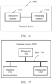
- an embodiment of this application provides an apparatus for determining a frequency domain location of a control resource set.
- the apparatus may be a terminal device, or may be a chip in a terminal device.
- the apparatus may include a processing unit and a transceiver unit.
- the processing unit may be a processor
- the transceiver unit may be a transceiver.
- the terminal device may further include a storage unit, and the storage unit may be a memory.
- the storage unit is configured to store instructions, and the processing unit executes the instructions stored in the storage unit, so that the terminal device performs the method performed by the terminal device in any one of the first aspect to the fourth aspect or any possible implementation thereof.
- the processing unit may be a processor, and the transceiver unit may be an input/output interface, a pin, a circuit, or the like.
- the processing unit executes instructions stored in a storage unit, so that the terminal device performs the method performed by the terminal device in any one of the first aspect to the fourth aspect or any possible implementation thereof.
- the storage unit may be a storage unit (for example, a register or a cache) in the chip, or may be a storage unit (for example, a read-only memory or a random access memory) located outside the chip and in the terminal device.
- an embodiment of this application provides an apparatus for determining a frequency domain location of a control resource set.
- the apparatus may be a network device, or may be a chip in a network device.
- the apparatus may include a processing unit and a transceiver unit.
- the processing unit may be a processor
- the transceiver unit may be a transceiver.
- the network device may further include a storage unit, and the storage unit may be a memory.
- the storage unit is configured to store instructions, and the processing unit executes the instructions stored in the storage unit, so that the network device performs the method performed by the network device in any one of the first aspect to the fourth aspect or any possible implementation thereof.
- the processing unit may be a processor, and the transceiver unit may be an input/output interface, a pin, a circuit, or the like.
- the processing unit executes instructions stored in a storage unit, so that the network device performs the method performed by the network device in any one of the first aspect to the fourth aspect or any possible implementation thereof.
- the storage unit may be a storage unit (for example, a register or a cache) in the chip, or may be a storage unit (for example, a read-only memory or a random access memory) located outside the chip and in the network device.
- an embodiment of this application provides a computer program product.
- the computer program product includes computer program code.
- the computer program code is run on a computer, the computer is enabled to perform the method performed by the terminal device in any one of the first aspect to the fourth aspect or any possible implementation thereof.
- an embodiment of this application provides a computer program product.
- the computer program product includes computer program code.
- the computer program code When the computer program code is run on a computer, the computer is enabled to perform the method performed by the network device in any one of the first aspect to the fourth aspect or any possible implementation thereof.
- an embodiment of this application provides a computer-readable medium.
- the computer-readable medium stores program code.
- the computer program code is run on a computer, the computer is enabled to perform the method performed by the terminal device in any one of the first aspect to the fourth aspect or any possible implementation thereof.
- an embodiment of this application provides a computer-readable medium.
- the computer-readable medium stores program code.
- the computer program code is run on a computer, the computer is enabled to perform the method performed by the network device in any one of the first aspect to the fourth aspect or any possible implementation thereof.
- FIG. 1 is a possible schematic architectural diagram of a communication system according to an embodiment of this application.
- the communication system includes a network device 101 and a terminal device 102.
- the network device 101 and the terminal device 102 may communicate with each other by using an air interface technology of the communication system.
- the communication includes a scenario in which uplink or downlink scheduling control information is transmitted on a physical downlink control channel (physical downlink control channel, PDCCH).
- PDCCH physical downlink control channel
- the PDCCH includes a time-frequency location of a commonControlResourceSet.
- a frequency domain location of the commonControlResourceSet namely, a location of a common resource block (common resource block, CRB) is determined by using a current active downlink bandwidth part as a reference. For example, when the current active downlink bandwidth part is an initial downlink bandwidth part, the location of the CRB in the commonControlResourceSet is determined by using the initial downlink bandwidth part as a reference.
- the terminal device may monitor the physical downlink control channel at the frequency domain location of the commonControlResourceSet to obtain the uplink or downlink scheduling control information.
- the network device may send the uplink or downlink scheduling control information on the physical downlink control channel at the frequency domain location of the commonControlResourceSet.
- the uplink or downlink scheduling control information may be control information for scheduling a random access response, control information for scheduling a paging message, or control information for scheduling a system message.
- initial downlink bandwidth part there are two configuration manners for the initial downlink bandwidth part (initial downlink bandwidth part, initial DL BWP).
- One configuration manner is defining the initial downlink bandwidth part by using a CORESET #0. In this case, a size and a frequency domain location of the initial downlink bandwidth part are the same as those of the CORESET #0.
- the CORESET is a control resource set (control resource set).
- the other configuration manner is configuring the initial DL BWP in a system information block 1 (System Information Block 1, SIB1).
- SIB1 System Information Block 1
- the initial downlink bandwidth part defined by using the CORESET#0 takes effect.
- the initial DL BWP configured in the SIB 1 takes effect.
- the initial DL BWP configured in the SIB 1 may be different from the initial DL BWP defined by using the CORESET #0, but a frequency domain location of the initial DL BWP configured in the SIB1 needs to include a frequency domain location of the CORESET #0.
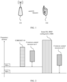
- FIG. 2 is a possible example diagram of frequency domain locations of common control resource sets according to an embodiment of this application.
- a frequency domain location of a CORESET #0 is inconsistent with a frequency domain location of an initial DL BWP configured in a SIB1, and a start resource block location RB-x of the CORESET #0 is different from a start resource block location RB-y of the initial DL BWP configured in the SIB 1.
- a start resource block location that is of a commonControlResourceSet 1 and that is determined based on an initial downlink bandwidth part defined by using the CORESET #0 is also different from a start resource block location that is of a commonControlResourceSet 2 and that is determined based on the initial DL BWP configured in the SIB 1.
- the terminal device Before successful initial access of a terminal device, the terminal device monitors control information for scheduling a random access response, a paging message, a system message, and the like based on a frequency domain location of the commonControlResourceSet 1. After the successful initial access of the terminal device, the terminal device monitors the information for scheduling the random access response, the paging message, the system message, and the like based on a frequency domain location of the commonControlResourceSet 2.
- a network device in coverage of a network device, if there is a terminal device whose initial access is successful and a terminal device whose access is unsuccessful, the network device needs to send, at the frequency domain location of the commonControlResourceSet 1, the scheduling information of the random access response, the paging message, the system message, and the like to the terminal device whose access is unsuccessful, and needs to send, at the frequency domain location of the commonControlResourceSet 2, the scheduling information of the random access response, the paging message, the system message, and the like to the terminal device whose initial access is successful.
- frequency domain locations of a commonControlResourceSet that are obtained through calculation before and after the successful initial access of the terminal device are different. Consequently, same common information is sent on different frequency domain resources, and both the terminal device and the network device separately calculate the frequency domain locations of the commonControlResourceSet depending on whether the access is successful, thereby increasing complexity of determining the frequency domain locations of the commonControlResourceSet.
- frequency domain locations of a commonControlResourceSet that are obtained through calculation before and after successful initial access of a terminal device may be the same.
- the terminal device and a network device need to calculate the frequency domain location of the commonControlResourceSet only once, thereby reducing complexity of determining the frequency domain location of the commonControlResourceSet.
- a terminal device in this application may be user equipment (user equipment, UE), or may be a handheld terminal, a notebook computer, a subscriber unit (subscriber unit), a cellular phone (cellular phone), a smartphone (smartphone), a personal digital assistant (personal digital assistant, PDA) computer, a tablet computer, a wireless modem (modem), a handheld (handheld) device, a laptop computer (laptop computer), a cordless phone (cordless phone), a wireless local loop (wireless local loop, WLL) station, a machine type communication (machine type communication, MTC) terminal, or another device that can access a mobile network.
- the terminal device and a network device communicate with each other by using an air interface technology.
- a network device in this application may be an access network device, and is mainly responsible for functions such as radio resource management, quality of service (quality of service, QoS) management, and data compression and encryption on an air interface side.
- the network device may include base stations in various forms, such as a macro base station, a micro base station (also referred to as a small cell), a relay station, and an access point.
- names of a device that has a base station function may be different.
- the device in a fifth generation (5th generation, 5G) system, the device is referred to as a gNB; in a fourth generation
- 5G fifth generation
- the device is referred to as an evolved NodeB (evolved NodeB, eNB or eNodeB).
- evolved NodeB evolved NodeB, eNB or eNodeB.
- a first control resource set in this application may alternatively be a common control resource set or a control resource set named in another manner. This is not limited in the embodiments of this application.
- the embodiments of this application may alternatively be applied to another communication system in which a frequency domain location of a control resource set needs to be determined.
- Terms "system” and “network” may be interchanged with each other.
- the system architecture described in the embodiments of this application aims to describe the technical solutions in the embodiments of this application, but do not constitute a limitation on the technical solutions provided in the embodiments of this application.
- a person of ordinary skill in the art may know that, as a network architecture evolves, the technical solutions provided in the embodiments of this application are also applicable to a similar technical problem.
- "a plurality of” means two or more, and "at least two" means two or more.
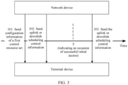
- FIG. 3 is a schematic flowchart of a method for determining a frequency domain location of a control resource set according to an embodiment of this application.
- the method shown in FIG. 3 includes step 301 to step 303.
- the network device sends configuration information of a first control resource set to the terminal device before successful initial access of the terminal device.
- the terminal device receives the configuration information of the first control resource set before the successful initial access of the terminal device.
- the network device sends, based on a first common resource block set occupied by the first control resource set, the uplink or downlink scheduling control information on the physical downlink control channel before the successful initial access of the terminal device.
- the terminal device monitors, based on the first common resource block set occupied by the first control resource set, the physical downlink control channel before the successful initial access of the terminal device, to obtain the uplink or downlink scheduling control information.
- the network device sends, based on the first common resource block set occupied by the first control resource set, the uplink or downlink scheduling control information on the physical downlink control channel after the successful initial access of the terminal device.
- the terminal device monitors, based on the first common resource block set occupied by the first control resource set, the physical downlink control channel after the successful initial access of the terminal device, to obtain the uplink or downlink scheduling control information.
- a quantity of execution times of step 302 and step 303 is not limited in this embodiment of this application.
- the configuration information is used to indicate where a physical resource block (physical resource block, PRB) occupied by the first control resource set is located in a first downlink bandwidth part. An identifier of the first control resource set in this application is not 0.
- the configuration information of the first control resource set may be obtained from a SIB1, and the configuration information may take effect both before and after the successful initial access of the terminal device. Taking effect herein means that the terminal device may monitor the physical downlink control channel based on a frequency domain location of the first control resource set, to obtain the uplink or downlink scheduling control information, or the network device may send the uplink or downlink scheduling control information on the physical downlink control channel based on a frequency domain location of the first control resource set.
- configuration information of the first downlink bandwidth part may also be obtained from the SIB1, but the configuration information of the first downlink bandwidth part configured in the SIB 1 takes effect after the successful initial access of the terminal device.
- Taking effect herein means that downlink control information may be received based on a frequency domain location of the first downlink bandwidth part configured in the SIB1, or the network device may send downlink control information based on a frequency domain location of the first downlink bandwidth part configured in the SIB 1.
- the terminal device may determine the frequency domain location of the first downlink bandwidth part by using one piece of higher layer signaling locationAndBandwidth and/or another parameter of the first downlink bandwidth part.
- First common resource blocks occupied by the first control resource set include a first start common resource block and a common resource block occupied by the first control resource set.
- both the network device and the terminal device may determine the first start common resource block, and may determine, based on the configuration information and a start common resource block of a referenced downlink bandwidth part, the common resource blocks that are occupied by the first control resource set and that start from the first start common resource block. How to determine the first start common resource block may be described in the following two cases (an A1 th case and an A2 th case).
- FIG. 4 is an example diagram of frequency domain locations of control resource sets according to an embodiment of this application.
- a first downlink bandwidth part is an initial DL BWP defined by using a CORESET #0
- a first start common resource block of a first control resource set is determined based on a second start common resource block of the CORESET #0 and configuration information of the first control resource set.
- a fourth offset refers to a quantity of common resource blocks between the second start common resource block of the CORESET #0 and the first start common resource block of the first control resource set.
- the second start common resource block of the CORESET #0 is a lowest CRB occupied by the CORESET #0.
- the first start common resource block of the first control resource set is a lowest CRB occupied by the first control resource set.
- the second start common resource block of the CORESET #0 is determined based on a second start physical resource block of the CORESET #0 and a first offset.
- the first offset is used to indicate a quantity of physical resource blocks between the second start physical resource block and a reference point.
- the reference point is a common reference point for resource block grids.
- the reference point is used to indicate a center of a subcarrier 0 of a common resource block CRB 0 configured at a preset subcarrier spacing. As shown in FIG.
- the common reference point may be a location of a point A (point A), and indicates the center of the subcarrier 0 of the common resource block CRB 0.
- the first offset is determined based on a second offset between the second start physical resource block of the first downlink bandwidth part and a third start physical resource block of an SS/PBCH block (Synchronization/ Physical Broadcast Channel block, synchronous/physical broadcast channel block) and a common resource block offset of the SS/PBCH block.
- the second offset is used to indicate a quantity of physical resource blocks between the second start physical resource block and the third start physical resource block of the SS/PBCH block.
- the common resource block offset of the SS/PBCH block is used to indicate a quantity of physical resource blocks between the third start physical resource block and the reference point.
- an offset relative to point A is equal to N CRB SSB .
- the first offset is equal to a value obtained by subtracting the second offset from N CRB SSB .
- the third start physical resource block is an RB that has a smallest RB index value and that is in CRBs overlapping the first RB of the SS/PBCH block.
- the first downlink bandwidth part may be defined by using only the CORESET #0. In this way, a frequency domain location of the first control resource set can be determined by using only the first downlink bandwidth part defined by using the CORESET #0.
- the first downlink bandwidth part may be defined by using the CORESET #0, and the first downlink bandwidth part may be configured in a SIB 1. In this case, the first downlink bandwidth part defined by using the CORESET #0 is selected to determine a frequency domain location of the first control resource set.
- the terminal device Before successful initial access of a terminal device, the terminal device may obtain the configuration information of the first control resource set from a SIB 1 message. Before the successful initial access of the terminal device, a network device may use the SIB1 message to carry the configuration information of the first control resource set. The terminal device and the network device may determine a first start common resource location of the first control resource set based on the second start common resource block of the CORESET #0. Before the successful initial access of the terminal device, the terminal device monitors a physical downlink control channel based on a first control resource set 1 shown in FIG. 4 , to obtain uplink or downlink scheduling control information, and the network device sends the uplink or downlink scheduling control information on the physical downlink control channel based on the first control resource set 1 shown in FIG. 4 .
- the terminal device monitors the physical downlink control channel based on a first control resource set 2 shown in FIG. 4 , to obtain the uplink or downlink scheduling control information, and the network device sends the uplink or downlink scheduling control information on the physical downlink control channel based on the first control resource set 2 shown in FIG. 4 .
- Frequency domain locations of the first control resource set that are determined in this manner are the same, and the terminal device and the network device need to calculate the location of the first control resource set only once, thereby reducing complexity of determining the frequency domain location of the first control resource set.
- the frequency domain location of the first control resource set may be determined before the successful initial access of the terminal device and based on the configuration information and a frequency domain location of the first downlink bandwidth part defined by using the CORESET #0.
- the frequency domain location of the first control resource set may be determined after the successful initial access and based on the configuration information and a frequency domain location of the first downlink bandwidth part defined by using the CORESET #0.
- FIG. 5 is another example diagram of frequency domain locations of control resource sets according to an embodiment of this application.
- a first downlink bandwidth part is an initial DL BWP configured in a SIB1
- a first start common resource block of a first control resource set is determined based on a second start common resource block of the first downlink bandwidth part configured in the SIB1 and configuration information of the first control resource set.
- a fifth offset refers to a quantity of common resource blocks between the second start common resource block of the first downlink bandwidth part configured in the SIB 1 and the first start common resource block of the first control resource set.
- the second start common resource block of the first downlink bandwidth part is determined based on a second start physical resource block of the first downlink bandwidth part and a third offset.
- the third offset is used to indicate a quantity of physical resource blocks between the second start physical resource block and a reference point.
- the reference point is a common reference point for resource block grids.
- the reference point is used to indicate a center of a subcarrier 0 of a common resource block CRB 0 configured at a preset subcarrier spacing.
- the common reference point may be a point A (point A), and indicates the center of the subcarrier 0 of the common resource block CRB 0.
- the first downlink bandwidth part there may be only one manner of configuring the first downlink bandwidth part, to be specific, by using the SIB 1.
- a frequency domain location of the first control resource set can be determined by using only the first downlink bandwidth part configured in the SIB1.
- the first downlink bandwidth part may be configured by using a CORESET #0 and the SIB1.
- the first downlink bandwidth part configured in the SIB1 is selected to determine a frequency domain location of the first control resource set.
- the terminal device Before successful initial access of a terminal device, the terminal device may obtain the configuration information of the first control resource set from a SIB 1 message. Before the successful initial access of the terminal device, a network device may use the SIB 1 message to carry the configuration information of the first control resource set. The terminal device and the network device may determine a first start common resource location of the first control resource set based on the second start common resource block of the first downlink bandwidth part configured in the SIB 1. Before the successful initial access of the terminal device, the terminal device monitors a physical downlink control channel based on a first control resource set 1 shown in FIG.
- the network device sends the uplink or downlink scheduling control information on the physical downlink control channel based on the first control resource set 1 shown in FIG. 5 .
- the terminal device monitors the physical downlink control channel based on a first control resource set 2 shown in FIG. 5 , to obtain the uplink or downlink scheduling control information, and the network device sends the uplink or downlink scheduling control information on the physical downlink control channel based on the first control resource set 2 shown in FIG. 5 .
- Frequency domain locations of the first control resource set that are determined in this manner are the same, and the terminal device and the network device need to calculate the location of the first control resource set only once, thereby reducing complexity of determining the frequency domain location of the first control resource set.
- the frequency domain location of the first control resource set may be determined before the successful initial access of the terminal device and based on the configuration information and a frequency domain location of the first downlink bandwidth part configured in the SIB1.
- the frequency domain location of the first control resource set may be determined after the successful initial access of the terminal device and based on the configuration information and a frequency domain location of the first downlink bandwidth part configured in the SIB 1.
- An occasion T in FIG. 3 , FIG. 4 , and FIG. 5 indicates an occasion of the successful initial access of the terminal device.
- the network device and the terminal device may define the occasion T differently.
- the terminal device determines that the occasion of the successful initial access is used to indicate one of the following occasions (3-1), (3-2), (3-3), (3-4), (3-5), or (3-6), where
- the network device determines that the occasion of the successful initial access is used to indicate one of the following occasions (3-7), (3-8), (3-9), or (3-10), where
- frequency domain locations of the first control resource set before and after the successful initial access of the terminal device are the same.
- the terminal device and the network device need to calculate the frequency domain location of the first control resource set only once, thereby reducing complexity of determining the frequency domain location of the first control resource set.
- FIG. 6 is an example diagram of a frequency domain location of a downlink bandwidth part and a frequency domain location of a first control resource set according to this application.
- a network device may indicate resource allocation of the first control resource set in the BWP by using higher layer signaling frequencyDomainResources.
- the "frequencyDomainResources" herein is configuration information of the first control resource set in this application.
- the frequencyDomainResources is a 45-bit bitmap (bit-map).
- the 45-bit bitmap indicates frequency domain resource allocation of the first control resource set in a first downlink bandwidth part, and each bit indicates six consecutive non-overlapping physical resource blocks (Physical Resource block, PRB).
- An index of a first start common resource block of the first control resource set is aligned with an index that is of a common resource block and that is a multiple of 6.
- CRB 36 CRB 36.
- six PRBs indicated by the first bit of the 45-bit bitmap are successively arranged in ascending order from CRB 36. If a value of a bit is 1, it indicates that six corresponding consecutive PRBs are allocated to the first control resource set. If a value of a bit is 0, it indicates that six corresponding consecutive PRBs are not allocated to the first control resource set. If a PRB part indicated by a bit exceeds the downlink bandwidth part, an excess part is set to 0, indicating that the excess part is not allocated to the first control resource set.
- the downlink bandwidth part (DL BWP) in FIG. 6 may be an initial downlink bandwidth part defined by using the CORESET #0, may be an initial downlink bandwidth part configured by using a SIB1, may be a newly configured initial DL BWP, or may be another DL BWP or the like.
- DL BWP downlink bandwidth part
- For all the various possible configuration cases of the downlink bandwidth part refer to how to determine the first start common resource block of the first control resource set based on the start common resource block of the downlink bandwidth part and the configuration information of the first control resource set in FIG. 6 .
- FIG. 7 is an example diagram of a time domain resource of a first control resource set according to an embodiment of this application.
- a network device may configure a first control resource set for a terminal device by using higher layer signaling (for example, radio resource control (Radio Resource Control, RRC) signaling), namely, a configuration message of the first control resource set.
- the configuration message includes parameters such as a CORESET ID of the first control resource set, a frequency domain resource indication, and a quantity of OFDM symbols of the first control resource set in time domain.
- the quantity of OFDM symbols of the first control resource set in time domain may be one of 1, 2, and 3.
- the frequency domain resource indication may be the 45-bit bitmap shown in FIG. 6 .
- the network device configures a search space set for the terminal device by using higher layer signaling (for example, RRC signaling), namely, a SearchSpace configuration message.
- the SearchSpace configuration message includes parameters such as a search space set ID, a monitoring occasion (monitoring occasion) indication in a slot (slot), an aggregation level, and a quantity of corresponding candidate PDCCHs. For example, a time domain location of the first control resource set in which blind detection is performed in search space is shown in FIG. 7 .
- a monitoring occasion indication of the search space in a slot 0 is on the first symbol in the slot 0.
- the first control resource set corresponding to the CORESET ID in the search space lasts for three symbols in time domain, for example, a symbol 0 to a symbol 2 in FIG. 7 .
- a frequency domain resource location of the first control resource set is determined by using the 45-bit bitmap.
- for a specific process of determining a frequency domain location of the first control resource set refer to the descriptions of the method shown in FIG. 6 .
- a downlink bandwidth part is defined by using a CORESET #0 or configured in a SIB 1
- an initial downlink bandwidth part defined by using the CORESET #0 is represented by a downlink bandwidth part 1
- an initial downlink bandwidth part configured in the SIB1 is represented by a downlink bandwidth part 2
- a detailed process of determining frequency domain locations of the downlink bandwidth part 1 and the downlink bandwidth part 2 refer to detailed descriptions in FIG. 8 .
- a common resource block of the downlink bandwidth part 1 herein is represented by a fifth common resource block, and the fifth common resource block includes a fifth start common resource block and another common resource block occupied by the downlink bandwidth part 1;
- a common resource block of the downlink bandwidth part 2 herein is represented by a sixth common resource block, and the sixth common resource block includes a sixth start common resource block and another common resource block occupied by the downlink bandwidth part 2.
- the second offset herein is a quantity of physical resource blocks between a fifth start physical resource block of the downlink bandwidth part 1 and the third start physical resource block of the SS/PBCH block, and the second offset is in a unit of PRB.
- the fifth start physical resource block of the downlink bandwidth part 1 may be determined based on the third start physical resource block of the SS/PBCH block and the second offset.
- DCI format 1_0 scrambled by using a SI-RNTI is monitored in the downlink bandwidth part 1, to obtain scheduling information of the SIB1, and a SIB1 message is received on a scheduled time-frequency resource.
- the following information may be obtained by obtaining a ServingCellConfigCommonSIB in the SIB 1 message.
- a third start common resource block of the SS/PBCH block may be determined based on the offsetToPointA and the third start physical resource location in the SS/PBCH block.
- the third start common resource block is the CRB that has the smallest index value and that overlaps with the first RB of the SS/PBCH block.
- a first offset may be determined by using the offsetToPointA and the second offset in (2), and the fifth start common resource block of the downlink bandwidth part 1 may be determined based on the first offset and the fifth start physical resource block of the downlink bandwidth part 1.
- the fifth start common resource block is a lowest common resource block occupied by the downlink bandwidth part 1.
- locationAndBandwidth is used to indicate information such as a start physical resource block of the downlink bandwidth part 2 and a quantity of the common resource blocks occupied by the downlink bandwidth part 2, as shown in FIG. 8 .
- carrierBandwidth is used to indicate a group of carriers corresponding to different subcarrier spacings and a width of each carrier in frequency domain.
- OffsetToCarrier is used to indicate a frequency domain offset from a lowest available subcarrier of each carrier to the point A, where the point A is a center of a subcarrier 0 of a common RB.
- the sixth start common resource block of the downlink bandwidth part 2 and the another common resource block occupied by the downlink bandwidth part 2 may be determined with reference to II and III.
- the sixth start common resource block is a lowest common resource block occupied by the downlink bandwidth part 2.
- the resource block grid in the embodiments of this application is used to map a physical resource.
- a basic unit is a time-frequency resource element (Resource Element, RE).
- RE resource Element
- One RE consists of one symbol in time domain and one subcarrier in frequency domain.
- One resource block (Resource Block, RB) includes all OFDM symbols in one slot and 12 subcarriers in frequency domain.
- a location of the RE is represented by using (k, l).
- k represents a sequence number of the OFDM symbol
- 1 represents a sequence number of the subcarrier, and a specified RE may be located by providing coordinates (k, 1).
- the terminal device may obtain the configuration information of the first control resource set by using the ServingCellConfigCommonSIB in the SIB 1 message, and may further determine the first start common resource block that is of the first control resource set and that uses the downlink bandwidth part 1 as a reference, or determine the first start common resource block that is of the first control resource set and that uses the downlink bandwidth part 2 as a reference.
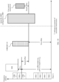
- FIG. 9 is a schematic flowchart of another method for determining a frequency domain location of a control resource set according to an embodiment of this application.
- the method shown in FIG. 9 includes step 901 and step 902.
- the network device sends configuration information of a first control resource set to the terminal device before successful initial access of the terminal device.
- the terminal device receives the configuration information of the first control resource set before the successful initial access of the terminal device.
- the network device sends, based on a first common resource block set occupied by the first control resource set, the uplink or downlink scheduling control information on the physical downlink control channel after the successful initial access of the terminal device.
- the terminal device monitors, based on the first common resource block set occupied by the first control resource set, the physical downlink control channel after the successful initial access of the terminal device, to obtain the uplink or downlink scheduling control information.
- the configuration information is used to indicate where a physical resource block (physical resource block, PRB) occupied by the first control resource set is located in a first downlink bandwidth part.
- An identifier of the first control resource set in this application is not 0.
- the terminal device Before the successful initial access of the terminal device, the terminal device does not monitor the physical downlink control channel based on a common resource block set occupied by the first control resource set.
- a frequency domain location of the first control resource set is determined by using a downlink bandwidth part as a reference. For details, refer to specific descriptions in FIG. 10 and FIG. 11 .
- the configuration information of the first control resource set may be obtained from a SIB1, and the configuration information may take effect after the successful initial access of the terminal device. Taking effect herein means that the terminal device may monitor the physical downlink control channel based on the frequency domain location of the first control resource set, to obtain the uplink or downlink scheduling control information, or the network device may send the uplink or downlink scheduling control information on the physical downlink control channel based on the frequency domain location of the first control resource set.
- configuration information of the first downlink bandwidth part may also be obtained from the SIB1, but the configuration information of the first downlink bandwidth part configured in the SIB 1 takes effect after the successful initial access of the terminal device.
- Taking effect herein means that downlink control information may be received based on a frequency domain location of the first downlink bandwidth part configured in the SIB1, or the network device may send downlink control information based on a frequency domain location of the first downlink bandwidth part configured in the SIB 1.
- the terminal device may determine the frequency domain location of the first downlink bandwidth part by using one piece of higher layer signaling locationAndBandwidth and/or another parameter of the first downlink bandwidth part.
- the first common resource blocks occupied by the first control resource set include a first start common resource block and another common resource block occupied by the first control resource set.
- both the network device and the terminal device may determine the first start common resource block, and may determine, based on the configuration information and a start common resource block of the referenced downlink bandwidth part, the common resource blocks that are occupied by the first control resource set and that start from the first start common resource block. How to determine the first start common resource block may be described in the following two cases (a B1 th case and a B2 th case).
- FIG. 10 is another example diagram of a frequency domain location of a control resource set according to an embodiment of this application.
- a first downlink bandwidth part is an initial DL BWP defined by using a CORESET #0
- a first start common resource block of a first control resource set is determined based on a second start common resource block of the CORESET #0 and configuration information of the first control resource set.
- a fourth offset refers to a quantity of common resource blocks between the second start common resource block of the CORESET #0 and the first start common resource block of the first control resource set.
- the second start common resource block of the CORESET #0 is a lowest CRB occupied by the CORESET #0.
- the first start common resource block of the first control resource set is a lowest CRB occupied by the first control resource set.
- the second start common resource block of the CORESET #0 is determined based on a second start physical resource block of the CORESET #0 and a first offset.
- the first offset is used to indicate a quantity of physical resource blocks between the second start physical resource block and a reference point.
- the reference point is a common reference point for resource block grids.
- the reference point is used to indicate a center of a subcarrier 0 of a common resource block CRB 0 configured at a preset subcarrier spacing. As shown in FIG. 10 , the common reference point may be a location of a point A (point A), and indicates the center of the subcarrier 0 of the common resource block CRB 0.
- the first offset is determined based on a second offset between the second start physical resource block of the first downlink bandwidth part and a third start physical resource block of an SS/PBCH block and a common resource block offset of the SS/PBCH block.
- the second offset is used to indicate a quantity of physical resource blocks between the second start physical resource block and the third start physical resource block of the SS/PBCH block.
- the common resource block offset of the SS/PBCH block is used to indicate a quantity of physical resource blocks between the third start physical resource block and the reference point.
- an offset relative to point A (offsetToPointA) is equal to N CRB SSB .
- the first offset is equal to a value obtained by subtracting the second offset from N CRB SSB .
- the third start physical resource block is an RB that has a smallest RB index value and that is in CRBs overlapping the first RB of the SS/PBCH block.
- the first downlink bandwidth part is defined by using the CORESET #0.
- the first downlink bandwidth part may be configured/defined by using the CORESET #0 and a SIB1.
- the first downlink bandwidth part defined by using the CORESET #0 is selected to determine a frequency domain location of the first control resource set.
- the terminal device Before successful initial access of a terminal device, the terminal device may obtain the configuration information of the first control resource set from a SIB 1 message. Before the successful initial access of the terminal device, a network device may use the SIB1 message to carry the configuration information of the first control resource set. The terminal device and the network device may determine a first start common resource location of the first control resource set based on the second start common resource block of the CORESET #0. After the successful initial access of the terminal device, the terminal device monitors a physical downlink control channel based on the first control resource set shown in FIG. 10 , to obtain uplink or downlink scheduling control information, and the network device sends the uplink or downlink scheduling control information on the physical downlink control channel based on the first control resource set shown in FIG. 10 . Frequency domain locations of the first control resource set that are determined in this manner are the same, and the terminal device and the network device need to calculate the location of the first control resource set only once, thereby reducing complexity of determining the frequency domain location of the first control resource set.
- the frequency domain location of the first control resource set may be determined before the successful initial access of the terminal device and based on the configuration information and a frequency domain location of the first downlink bandwidth part defined by using the CORESET #0.
- the frequency domain location of the first control resource set may be determined after the successful initial access of the terminal device and based on the configuration information and a frequency domain location of the first downlink bandwidth part defined by using the CORESET #0.
- FIG. 11 is another example diagram of a frequency domain location of a control resource set according to an embodiment of this application.
- a first downlink bandwidth part is an initial DL BWP configured in a SIB1
- a first start common resource block of a first control resource set is determined based on a second start common resource block of the first downlink bandwidth part configured in the SIB1 and configuration information of the first control resource set.
- a fifth offset refers to a quantity of common resource blocks between the second start common resource block of the first downlink bandwidth part configured in the SIB 1 and the first start common resource block of the first control resource set.
- the second start common resource block of the first downlink bandwidth part is determined based on a second start physical resource block of the first downlink bandwidth part and a third offset.
- the third offset is used to indicate a quantity of physical resource blocks between the second start physical resource block and a reference point.
- the reference point is a common reference point for resource block grids.
- the reference point is used to indicate a center of a subcarrier 0 of a common resource block CRB 0 configured at a preset subcarrier spacing.
- the common reference point may be a location of a point A (point A), and indicates the center of the subcarrier 0 of the common resource block CRB 0.
- point A point A
- the first downlink bandwidth part is configured by using the SIB 1.
- the first downlink bandwidth part may be configured by using a CORESET #0 and the SIB1.
- the first downlink bandwidth part configured in the SIB1 is selected to determine a frequency domain location of the first control resource set.
- the terminal device Before successful initial access of a terminal device, the terminal device may obtain the configuration information of the first control resource set from a SIB 1 message. Before the successful initial access of the terminal device, a network device may use the SIB1 message to carry the configuration information of the first control resource set. The terminal device and the network device may determine a first start common resource location of the first control resource set based on the second start common resource block of the first downlink bandwidth part configured in the SIB 1. After the successful initial access of the terminal device, the terminal device monitors a physical downlink control channel based on the first control resource set shown in FIG. 11 , to obtain uplink or downlink scheduling control information, and the network device sends the uplink or downlink scheduling control information on the physical downlink control channel based on the first control resource set shown in FIG.
- Frequency domain locations of the first control resource set that are determined in this manner are the same, and the terminal device and the network device need to calculate the location of the first control resource set only once, thereby reducing complexity of determining the frequency domain location of the first control resource set.
- the frequency domain location of the first control resource set may be determined before the successful initial access of the terminal device and based on the configuration information and a frequency domain location of the first downlink bandwidth part configured in the SIB1.
- the frequency domain location of the first control resource set may be determined after the successful initial access of the terminal device and based on the configuration information and a frequency domain location of the first downlink bandwidth part configured in the SIB 1.
- An occasion T in FIG. 9 , FIG. 10 , and FIG. 11 indicates an occasion of the successful initial access of the terminal device.
- the network device and the terminal device may define the occasion T differently.
- the terminal device determines that the occasion of the successful initial access is used to indicate one of the following occasions (10-1), (10-2), (10-3), (10-4), (10-5), or (10-6), where
- the network device determines that the occasion of the successful initial access is used to indicate one of the following occasions (10-7), (10-8), (10-9), or (10-10), where
- the network device before the successful initial access of the terminal device, the network device does not send the uplink or downlink scheduling control information on the physical downlink control channel based on the common resource block set occupied by the first control resource set, and the terminal device does not monitor the physical downlink control channel based on the frequency domain location of the first control resource set.
- the network device neither the network device nor the terminal device needs to determine the frequency domain location of the first control resource set before the successful initial access of the terminal device, and the frequency domain location that is of the first control resource set and that is after the initial access of the terminal device is determined by using the referenced downlink bandwidth part.
- the terminal device and the network device need to calculate the frequency domain location of the first control resource set only once, thereby reducing complexity of determining the frequency domain location of the first control resource set.
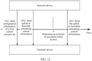
- FIG. 12 is a schematic flowchart of another method for determining a frequency domain location of a control resource set according to an embodiment of this application.
- the method shown in FIG. 12 includes step 1201 to step 1203.
- the network device sends configuration information of a first control resource set to the terminal device before successful initial access of the terminal device.
- the terminal device receives the configuration information of the first control resource set before the successful initial access of the terminal device.
- the network device sends, based on a first common resource block set occupied by the first control resource set, the uplink or downlink scheduling control information on the physical downlink control channel before the successful initial access of the terminal device.
- the terminal device monitors, based on the first common resource block set occupied by the first control resource set, the physical downlink control channel before the successful initial access of the terminal device, to obtain the uplink or downlink scheduling control information.
- the network device sends, based on a third common resource block set occupied by the first control resource set, the uplink or downlink scheduling control information on the physical downlink control channel after the successful initial access of the terminal device.
- a first start common resource block included in the first common resource block set is determined based on a second start common resource block of a first downlink bandwidth part and the configuration information of the first control resource set, and the configuration information is used to indicate where a physical resource block occupied by the first common control resource set is located in the first downlink bandwidth part.
- the first downlink bandwidth part herein may be defined by using a CORESET #0.
- An identifier of the first control resource set in this application is not 0.
- the configuration information of the first control resource set may be obtained from a SIB1, and the configuration information may take effect before or after the successful initial access of the terminal device. Taking effect herein means that the terminal device may monitor the physical downlink control channel based on a frequency domain location of the first control resource set, to obtain the uplink or downlink scheduling control information, or the network device may send the uplink or downlink scheduling control information on the physical downlink control channel based on a frequency domain location of the first control resource set.
- configuration information of the first downlink bandwidth part may also be obtained from the SIB1, but the configuration information of the first downlink bandwidth part configured in the SIB 1 takes effect after the successful initial access of the terminal device.
- the terminal device may determine a frequency domain location of the first downlink bandwidth part by using one piece of higher layer signaling locationAndBandwidth and/or another parameter of the first downlink bandwidth part, and may receive downlink control information based on the frequency domain location of the first downlink bandwidth part configured in the SIB1, or the network device may send downlink control information based on the frequency domain location of the first downlink bandwidth part configured in the SIB 1.
- FIG. 13 is another example diagram of frequency domain locations of control resource sets according to an embodiment of this application.
- a first downlink bandwidth part is an initial DL BWP defined by using a CORESET #0
- a first start common resource block of a first control resource set 1 is determined based on a second start common resource block of the CORESET #0 and configuration information of the first control resource set.
- a second downlink bandwidth part is an initial DL BWP configured in a SIB1
- a third start common resource block of a first control resource set 2 is determined based on a fourth start common resource block of the initial DL BWP configured in the SIB 1 and the configuration information of the first control resource set.
- the second start common resource block of the first downlink bandwidth part is the same as the fourth start common resource block of the second downlink bandwidth part.
- start common resource block of the CORESET #0 for a detailed process of determining the first start common resource block of the first control resource set 1 after the second start common resource block of the CORESET #0 is determined, refer to detailed descriptions in FIG. 6 .
- start common resource block of the CORESET #0 for a detailed process of determining the first start common resource block of the first control resource set 1 after the second start common resource block of the CORESET #0 is determined, refer to detailed descriptions in FIG. 6 .
- a fourth offset refers to a quantity of common resource blocks between the second start common resource block of the CORESET #0 and the first start common resource block of the first control resource set.
- an offset relative to point A (offsetToPointA) is equal to N CRB SSB .
- the first offset is equal to a value obtained by subtracting the second offset from N CRB SSB .
- the fourth start common resource block of the second downlink bandwidth part (the initial DL BWP configured in the SIB1 in FIG. 13 ) is determined based on a fourth start physical resource block of the second downlink bandwidth part and a third offset.
- the third offset is used to indicate a quantity of physical resource blocks between the fourth start physical resource block and the reference point.
- the reference point is a location of a point A (point A) in FIG. 13 .
- the terminal device Before successful initial access of a terminal device, the terminal device may obtain the configuration information of the first control resource set from a SIB 1 message. Before the successful initial access of the terminal device, a network device may use the SIB1 message to carry the configuration information of the first control resource set. The terminal device and the network device may determine a first start common resource location of the first control resource set 1 based on the second start common resource block of the CORESET #0, and may determine a third start common resource location of the first control resource set 2 based on the fourth start common resource block of the initial DL BWP configured in the SIB1.
- the terminal device Before the successful initial access of the terminal device, the terminal device monitors a physical downlink control channel based on the first control resource set 1 shown in FIG. 13 , to obtain uplink or downlink scheduling control information, and the network device sends the uplink or downlink scheduling control information on the physical downlink control channel based on the first control resource set 1 shown in FIG. 13 .
- the terminal device monitors the physical downlink control channel based on the first control resource set 2 shown in FIG. 13 , to obtain the uplink or downlink scheduling control information, and the network device sends the uplink or downlink scheduling control information on the physical downlink control channel based on the first control resource set 2 shown in FIG. 13 .
- Frequency domain locations of the first control resource set that are determined in this manner are the same, and the terminal device and the network device need to calculate the location of the first control resource set only once, thereby reducing complexity of determining the frequency domain location of the first control resource set.
- An occasion of determining the frequency domain location of the first control resource set is not limited in this embodiment of this application.
- the frequency domain location of the first control resource set only needs to be determined before monitoring/sending performed on the first control resource set 1 or the first control resource set 2. This is not limited in this embodiment of this application.
- An occasion T in FIG. 12 and FIG. 13 indicates an occasion of the successful initial access of the terminal device.
- the network device and the terminal device may define the occasion T differently.
- the terminal device determines that the occasion of the successful initial access is used to indicate one of the following occasions (13-1), (13-2), (13-3), (13-4), (13-5), (13-6), (13-7), (13-8), (13-9), or (13-10), where
- the network device determines that the occasion of the successful initial access is used to indicate one of the following occasions (13-11), (13-12), (13-13), or (13-14), where
- FIG. 14 is a schematic flowchart of another method for determining a frequency domain location of a control resource set according to an embodiment of this application.
- the method shown in FIG. 14 includes step 1401 and step 1402.
- the network device sends, based on a first common resource block set occupied by the first control resource set, the uplink or downlink scheduling control information on the physical downlink control channel after the successful initial access of the terminal device.
- the terminal device monitors, based on the first common resource block set occupied by the first control resource set, the physical downlink control channel after the successful initial access of the terminal device, to obtain the uplink or downlink scheduling control information.
- the configuration information is used to indicate where a physical resource block (physical resource block, PRB) occupied by the first control resource set is located in a first downlink bandwidth part.
- An identifier of the first control resource set in this application is not 0.
- the configuration information of the first control resource set is not configured before the successful initial access of the terminal device.
- the configuration information of the first control resource set is configured only after the successful initial access of the terminal device.
- the terminal device may monitor the physical downlink control channel based on the common resource block set occupied by the first control resource set.
- a frequency domain location of the first control resource set is determined by using a downlink bandwidth part as a reference. For details, refer to specific descriptions in FIG. 15 .
- the configuration information of the first control resource set may be obtained from a SIB1 after the successful initial access of the terminal device, and the configuration information may take effect after the successful initial access of the terminal device.
- Taking effect herein means that the terminal device may monitor the physical downlink control channel based on the frequency domain location of the first control resource set, to obtain the uplink or downlink scheduling control information, or the network device may send the uplink or downlink scheduling control information on the physical downlink control channel based on the frequency domain location of the first control resource set.
- the configuration information of the first control resource set may be configured, after the successful initial access of the terminal device, from another message for configuring the downlink bandwidth part. This is not limited in the embodiment shown in FIG. 14 .
- the configuration information of the first control resource set and configuration information of the first downlink bandwidth part are received simultaneously.
- the configuration information of the first control resource set is included in the configuration information of the first downlink bandwidth part.
- the frequency domain location of the first control resource set is determined by using, as a reference, the configuration information that is of the first downlink bandwidth part and that includes the configuration information of the first control resource set. In other words, after the successful initial access of the terminal device, both the configuration information of the first control resource set and the configuration information of the first downlink bandwidth part may be obtained from one configuration message.
- the frequency domain location of the first control resource set is determined based on the configuration information of the first downlink bandwidth part and the configuration information of the first control resource set.
- First common resource blocks occupied by the first control resource set include a first start common resource block and another common resource block occupied by the first control resource set.
- both the network device and the terminal device may determine the first start common resource block, and may determine, based on the configuration information and a start common resource block of the referenced downlink bandwidth part, the common resource blocks that are occupied by the first control resource set and that start from the first start common resource block.
- For how to determine the first start common resource block refer to specific descriptions in FIG. 15 .
- FIG. 15 is another example diagram of a frequency domain location of a control resource set according to an embodiment of this application.
- a first downlink bandwidth part is configured in a SIB 1 or by using another configuration message, and a first start common resource block of a first control resource set is determined based on a second start common resource block of the first downlink bandwidth part and configuration information of the first control resource set.
- the second start common resource block of the first downlink bandwidth part for a detailed process of determining the first start common resource block after the second start common resource block of the first downlink bandwidth part is determined refer to detailed descriptions in FIG. 6 .
- a fifth offset refers to a quantity of common resource blocks between the second start common resource block of the first downlink bandwidth part configured in the SIB 1 or by using the another configuration message and the first start common resource block of the first control resource set.
- the second start common resource block of the first downlink bandwidth part is determined based on a second start physical resource block of the first downlink bandwidth part and a third offset.
- the third offset is used to indicate a quantity of physical resource blocks between the second start physical resource block and a reference point.
- the reference point is a common reference point for resource block grids.
- the reference point is used to indicate a center of a subcarrier 0 of a common resource block CRB 0 configured at a preset subcarrier spacing.
- the common reference point may be a location of a point A (point A), and indicates the center of the subcarrier 0 of the common resource block CRB 0.
- point A point A
- the first downlink bandwidth part may be configured by using a CORESET #0 and another configuration message.
- the first downlink bandwidth part configured after successful initial access of a terminal device is selected to determine a frequency domain location of the first control resource set.
- the terminal device may obtain the configuration information of the first control resource set from a configuration message.
- a network device may use the configuration message to carry the configuration information of the first control resource set.
- the terminal device and the network device may determine a first start common resource location of the first control resource set based on the second start common resource block of the first downlink bandwidth part in the configuration message.
- the terminal device monitors a physical downlink control channel based on the first control resource set shown in FIG. 15 , to obtain uplink or downlink scheduling control information, and the network device sends the uplink or downlink scheduling control information on the physical downlink control channel based on the first control resource set shown in FIG. 15 .
- Frequency domain locations of the first control resource set that are determined in this manner are the same, and the terminal device and the network device need to calculate the location of the first control resource set only once, thereby reducing complexity of determining the frequency domain location of the first control resource set.
- An occasion T in FIG. 14 and FIG. 15 indicates an occasion of the successful initial access of the terminal device.
- the network device and the terminal device may define the occasion T differently.
- the terminal device determines that the occasion of the successful initial access is used to indicate one of the following occasions (15-1), (15-2), (15-3), (15-4), (15-5), or (15-6), where
- the network device determines that the occasion of the successful initial access is used to indicate one of the following occasions (15-7), (15-8), (15-9), or (15-10):
- the network device before the successful initial access of the terminal device, the network device does not send the uplink or downlink scheduling control information on the physical downlink control channel based on the common resource block set occupied by the first control resource set, and the terminal device does not monitor the physical downlink control channel based on the frequency domain location of the first control resource set.
- the network device neither the network device nor the terminal device needs to determine the frequency domain location of the first control resource set before the successful initial access of the terminal device, and the frequency domain location that is of the first control resource set and that is after the initial access of the terminal device is determined by using the referenced downlink bandwidth part.
- the terminal device and the network device need to calculate the frequency domain location of the first control resource set only once, thereby reducing complexity of determining the frequency domain location of the first control resource set.
- an occasion on which the network device configures the first control resource set is not limited.
- the configuration message of the first control resource set may be configured before the successful initial access of the terminal device, or may be configured after the successful initial access of the terminal device.
- the various implementable solutions described in FIG. 3 to FIG. 15 may be included.
- the terminal device may monitor the channel before the initial access, to obtain the configuration information of the first control resource set.
- the terminal device may monitor the channel after the initial access, to obtain the configuration information of the first control resource set.
- an occasion of configuring the downlink bandwidth part referenced by the first control resource set may not be limited.
- the network device configures a new downlink bandwidth part
- the location of the first control resource set may be determined with reference to a frequency domain location of the new downlink bandwidth part.
- an occasion on which the network device configures the first control resource set may be limited.
- a limitation is that the configuration message of the first control resource set may be configured after the successful initial access of the terminal device.
- the terminal device does not need to monitor the channel before the initial access, but the terminal device starts to monitor the channel after the successful initial access of the terminal device, to obtain the configuration information of the first control resource set. In this way, a power loss, of the terminal device, caused by uncertain monitoring can be reduced.
- an occasion of configuring the downlink bandwidth part referenced by the first control resource set may be limited.
- the configuration occasion of the downlink bandwidth part is after the successful initial access of the terminal device, once the network device configures a new downlink bandwidth part, when the terminal device receives configuration information of the new downlink bandwidth part, the location of the first control resource set may be determined with reference to a frequency domain location of the new downlink bandwidth part.
- the network device configures at least one of the first control resource set, a newly configured initial DL BWP, or another DL BWP (a non-initial DL BWP or a BWP whose BWP_ID is not 0) for the terminal device by using higher layer signaling (for example, RRC signaling).
- higher layer signaling for example, RRC signaling
- the frequency domain location of the first control resource set uses the CORESET #0 or the newly configured initial DL BWP as a reference.
- the network device configures the newly configured initial DL BWP for the terminal device by using the higher layer signaling (for example, the RRC signaling).
- the frequency domain location of the first control resource set uses the CORESET #0 or the newly configured initial DL BWP as a reference.
- the initial DL BWP is configured in the SIB1 before the successful initial access of the terminal device, and the configuration of the first control resource set is in the another DL BWP, the following two cases (1) and (2) are included.
- the terminal device when successfully receiving a message sent by the network device, the terminal device feeds back a 1-bit message to perform acknowledgement (Acknowledgement, ACK) or negative acknowledgement (Negative Acknowledgement, NACK) on the received message.
- the network device determines, depending on whether the terminal device feeds back an ACK message (a bit value is 1) or a NACK message (a bit value is 0), whether to send new data or perform retransmission.
- An occasion of sending a message in the embodiments of this application may be an occasion of starting sending the message or an occasion of confirming that sending of the message is completed. This is not limited in this application.
- the occasion that is of sending the acknowledgement message and that is designed in the embodiments in FIG. 3 to FIG. 15 may be an occasion of sending the acknowledgement message or an occasion of confirming that sending of the acknowledgement message is completed.
- the frequency domain resource location of the first control resource set is limited within a frequency domain resource range of the CORESET #0. That is, a frequency domain resource size of the first control resource set is less than or equal to a frequency domain resource size of the CORESET #0. If the first control resource set is not configured in the SIB1, but is configured in other higher layer signaling (for example, RRC signaling), a frequency domain resource location of the first control resource set may be within a frequency domain resource range of the CORESET #0, or may not be within a frequency domain resource range of the CORESET #0.
- a search space higher-layer parameter used for a random access channel is configured in the first downlink bandwidth part
- a frequency domain resource range of another downlink bandwidth part configured by the network device for the terminal device by using higher layer signaling includes a frequency domain resource range of the first downlink bandwidth part after the successful initial access, and a subcarrier spacing of the another downlink bandwidth part is the same as a subcarrier spacing of the first downlink bandwidth part
- the network device may configure, for the terminal device in the another downlink bandwidth part by using higher layer signaling (for example, RRC signaling), search space that is configured in the first downlink bandwidth part and that is used for a random access channel, and the terminal device monitors corresponding downlink control channel, for example, downlink control information scrambled by using an RA-RNTI, based on configuration information of the search space.
- An identifier of the current active downlink bandwidth part is a
- the terminal device and the network device include corresponding hardware structures and/or software modules for performing the functions.
- the embodiments of this application can be implemented in a form of hardware or a combination of hardware and computer software. Whether a function is performed by hardware or hardware driven by computer software depends on particular applications and design constraints of the technical solutions. A person skilled in the art may use different devices to implement the described functions for each particular application, but it should not be considered that the implementation goes beyond the scope of the technical solutions in the embodiments of this application.
- the terminal device and the network device may be divided into functional modules or functional units based on the foregoing device examples.
- each functional module or functional unit may be obtained through division based on each corresponding function, or two or more functions may be integrated into one processing module or processing unit.
- the integrated modules or units may be implemented in a form of hardware, or may be implemented in a form of a software functional module. It should be noted that, in this embodiment of this application, division into the modules or the units is an example, and is merely logical function division. During actual implementation, another division manner may be used.
- FIG. 16 is a schematic structural diagram of a terminal device according to an embodiment of this application.
- the terminal device is configured to implement the device embodiments in FIG. 3 to FIG. 15 .
- the terminal device 1600 includes a transceiver module 1601 and a processing module 1602.
- the transceiver module 1601 and the processing module 1602 are configured to implement content of the embodiments shown in FIG. 3 to FIG. 5 . Details are as follows.
- the transceiver module 1601 is configured to receive configuration information of a first control resource set before successful initial access of the terminal device.
- the processing module 1602 is configured to monitor, based on a first common resource block set occupied by the first control resource set, a physical downlink control channel before the successful initial access of the terminal device or after the successful initial access of the terminal device, to obtain uplink or downlink scheduling control information.
- a first start common resource block included in the first common resource block set is determined based on a second start common resource block of a first downlink bandwidth part and the configuration information of the first control resource set, and the configuration information is used to indicate where a physical resource block occupied by the first control resource set is located in the first downlink bandwidth part.
- the transceiver module 1601 and the processing module 1602 are configured to implement content of the embodiments shown in FIG. 9 to FIG. 11 . Details are as follows.
- the transceiver module 1601 is configured to receive configuration information of a first control resource set before successful initial access of the terminal device.
- the processing module 1602 is further configured to monitor, based on a first common resource block set occupied by the first control resource set, the physical downlink control channel after the successful initial access of the terminal device, to obtain uplink or downlink scheduling control information.
- a first start common resource block included in the first common resource block set is determined based on a second start common resource block of a first downlink bandwidth part and the configuration information of the first control resource set, and the configuration information is used to indicate where a physical resource block occupied by the first control resource set is located in the first downlink bandwidth part.
- the transceiver module 1601 and the processing module 1602 are configured to implement content of the embodiments shown in FIG. 12 and FIG. 13 . Details are as follows.
- the transceiver module 1601 is configured to receive configuration information of a first control resource set before successful initial access of the terminal device.
- the processing module 1602 is configured to monitor, based on a first common resource block set occupied by the first control resource set, a physical downlink control channel before the successful initial access of the terminal device, to obtain uplink or downlink scheduling control information, where a first start common resource block included in the first common resource block set is determined based on a second start common resource block of a first downlink bandwidth part and the configuration information of the first control resource set, and the configuration information is used to indicate where a physical resource block occupied by the first control resource set is located in the first downlink bandwidth part.
- the processing module 1602 is further configured to monitor, based on a third common resource block set occupied by the first control resource set, the physical downlink control channel after the successful initial access of the terminal device, to obtain the uplink or downlink scheduling control information, where a third start common resource block included in the third common resource block set is determined based on a fourth start common resource block of a second downlink bandwidth part and the configuration information of the first control resource set, and the configuration information is used to indicate where a physical resource block occupied by the first control resource set is located in the second downlink bandwidth part.
- the second start common resource block of the first downlink bandwidth part is the same as the fourth start common resource block of the second downlink bandwidth part.
- the transceiver module 1601 and the processing module 1602 are configured to implement content of the embodiments shown in FIG. 14 and FIG. 15 . Details are as follows.
- the transceiver module 1601 is configured to receive configuration information of a first control resource set after successful initial access of the terminal device.
- the processing module 1602 is configured to monitor, based on a first common resource block set occupied by the first control resource set, a physical downlink control channel after the successful initial access of the terminal device, to obtain uplink or downlink scheduling control information.
- a first start common resource block included in the first common resource block set is determined based on a second start common resource block of a first downlink bandwidth part and the configuration information of the first control resource set, and the configuration information is used to indicate where a physical resource block occupied by the first control resource set is located in the first downlink bandwidth part.
- the terminal device 1600 is configured to implement the steps performed by the terminal device in the embodiments in FIG. 3 to FIG. 15 .
- the functional blocks included in the terminal device in FIG. 16 and corresponding beneficial effects refer to the specific descriptions of the embodiments in FIG. 3 to FIG. 15 . Details are not described herein.
- the transceiver module may be a receiver or a receiver circuit.
- the transceiver module may be a communication interface of the terminal device.
- the processing module may be a processor.
- the terminal device 1600 in the embodiment shown in FIG. 16 may be implemented by using a terminal device 1160 shown in FIG. 17.
- FIG. 17 is a schematic structural diagram of another terminal device according to an embodiment of this application.
- the terminal device 1160 shown in FIG. 17 includes a processor 1701 and a transceiver 1702.
- the transceiver 1702 is configured to support information transmission between the terminal device 1160 and another terminal device or another device in the foregoing embodiments.
- the processor 1701 is configured to control and manage an action of the terminal device.
- the transceiver 1702 is configured to receive the messages in steps 301, 302, and 303 in the embodiment shown in FIG. 3 .
- the processing unit 1701 is configured to support the transceiver 1702 in performing the foregoing steps.
- the transceiver 1702 is configured to receive the messages in steps 901 and 902 in the embodiment shown in FIG. 9 .
- the processing unit 1701 is configured to support the transceiver 1702 in performing the foregoing steps.
- the transceiver 1702 is configured to receive the messages in steps 1201, 1202, and 1203 in the embodiment shown in FIG. 12 .
- the processing unit 1701 is configured to support the transceiver 1702 in performing the foregoing steps.
- the transceiver 1702 is configured to receive the messages in steps 1401 and 1402 in the embodiment shown in FIG. 14 .
- the processing unit 1701 is configured to support the transceiver 1702 in performing the foregoing steps.
- the processor 1701 and the transceiver 1702 are communicatively connected. For example, they are connected by using a bus 1704.
- the bus 1704 may be a PCI bus, an EISA bus, or the like.
- the bus 1704 may be classified into an address bus, a data bus, a control bus, and the like. For ease of representation, only one thick line is used to represent the bus in FIG. 17 , but this does not mean that there is only one bus or only one type of bus.
- the terminal device 1160 may further include a memory 1703.
- the memory 1703 is configured to store program code and data that are executed by the terminal device 1160.
- the processor 1701 is configured to execute the application program code stored in the memory 1703, to implement an action of the terminal device provided in any one of the embodiments shown in FIG. 3 to FIG. 15 .
- the terminal device may include one or more processors, and a structure of the terminal device 1160 does not constitute a limitation on this embodiment of this application.
- the processor 1701 may be a central processing unit (central processing unit, CPU), a general-purpose processor, a digital signal processor (digital signal processor, DSP), an application-specific integrated circuit (application-specific integrated circuit, ASIC), a field programmable gate array (field programmable gate array, FPGA) or another programmable logic device, a transistor logic device, a hardware component, or any combination thereof.
- the processor may implement or execute various example logical blocks, modules, and circuits described with reference to content disclosed in this application.
- the processor may alternatively be a combination of processors implementing a computing function, for example, a combination of one or more microprocessors or a combination of the DSP and a microprocessor.
- the transceiver 1704 may be a communication interface, a transceiver circuit, or the like.
- the transceiver is a general term. During specific implementation, the transceiver may include a plurality of interfaces.
- the memory 1703 may include a transitory memory (transitory memory), for example, a random access memory (random access memory, RAM).
- the memory 1703 may alternatively include a non-transitory memory (non-transitory memory), for example, a read-only memory (read-only memory, ROM), a flash memory (flash memory), a hard disk drive (hard disk drive, HDD), or a solid-state drive (solid-state drive, SSD).
- the memory 1703 may alternatively include a combination of the foregoing types of memories.
- An embodiment of this application further provides a computer storage medium.
- the computer storage medium may be configured to store computer software instructions used by the terminal device in the embodiment shown in FIG. 17 .
- the computer software instructions include a program designed for use by the terminal device to implement the foregoing embodiments.
- the storage medium includes but is not limited to a flash memory, a hard disk, or a solid-state drive.
- An embodiment of this application further provides a computer program product.
- the computer product is run by a computing device, data processing designed for the terminal device in the embodiment shown in FIG. 17 may be performed.
- FIG. 18 is a schematic structural diagram of another network device according to an embodiment of this application.
- the network device is configured to implement the embodiments in FIG. 8 and FIG. 9 .
- the network device 1800 includes a transceiver module 1801 and a processing module 1802.
- the transceiver module and the processing module are configured to implement content of the embodiments shown in FIG. 3 to FIG. 5 .
- the transceiver module 1801 is configured to send configuration information of a first control resource set to a terminal device before successful initial access of the terminal device.
- the processing module 1802 is configured to broadcast, based on a first common resource block set occupied by the first control resource set, uplink or downlink scheduling control information on a physical downlink control channel before the successful initial access of the terminal device or after the successful initial access of the terminal device.
- a first start common resource block included in the first common resource block set is determined based on a second start common resource block of a first downlink bandwidth part and the configuration information of the first control resource set, and the configuration information is used to indicate where a physical resource block occupied by the first control resource set is located in the first downlink bandwidth part.
- the transceiver module and the processing module are configured to implement content of the embodiments shown in FIG. 9 to FIG. 11 . Details are as follows.
- the transceiver module 1801 is configured to send configuration information of a first control resource set to a terminal device before successful initial access of the terminal device.
- the processing module 1802 is configured to skip, before the successful initial access of the terminal device, broadcasting uplink or downlink scheduling control information on a physical downlink control channel based on a common resource block set occupied by the first control resource set.
- the processing module 1802 is further configured to broadcast, after the successful initial access of the terminal device, the uplink or downlink scheduling control information on the physical downlink control channel based on a first common resource block set occupied by the first control resource set.
- a first start common resource block included in the first common resource block set is determined based on a second start common resource block of a first downlink bandwidth part and the configuration information of the first control resource set, and the configuration information is used to indicate where a physical resource block occupied by the first control resource set is located in the first downlink bandwidth part.
- the transceiver module and the processing module are configured to implement content of the embodiments shown in FIG. 12 and FIG. 13 . Details are as follows.
- the transceiver module 1801 is configured to send, by the network device, configuration information of a first control resource set to a terminal device before successful initial access of the terminal device.
- the processing module 1802 is configured to broadcast, based on a first common resource block set occupied by the first control resource set, uplink or downlink scheduling control information on a physical downlink control channel before the successful initial access of the terminal device, where a first start common resource block included in the first common resource block set is determined based on a second start common resource block of a first downlink bandwidth part and the configuration information of the first control resource set, and the configuration information is used to indicate where a physical resource block occupied by the first control resource set is located in the first downlink bandwidth part.
- the processing module 1802 is further configured to broadcast, after the successful initial access of the terminal device, the uplink or downlink scheduling control information on the physical downlink control channel based on a third common resource block set occupied by the first control resource set, where a third start common resource block included in the third common resource block set is determined based on a fourth start common resource block of a second downlink bandwidth part and the configuration information of the first control resource set, and the configuration information is used to indicate where a physical resource block occupied by the first control resource set is located in the second downlink bandwidth part.
- the second start common resource block of the first downlink bandwidth part is the same as the fourth start common resource block of the second downlink bandwidth part.
- the transceiver module and the processing module are configured to implement content of the embodiments shown in FIG. 14 and FIG. 15 . Details are as follows.
- the processing module 1802 is configured to broadcast, based on a first common resource block set occupied by the first control resource set, uplink or downlink scheduling control information on a physical downlink control channel after the successful initial access of the terminal device, where a first start common resource block included in the first common resource block set is determined based on a second start common resource block of a first downlink bandwidth part and the configuration information of the first control resource set, and the configuration information is used to indicate where a physical resource block occupied by the first control resource set is located in the first downlink bandwidth part.
- the network device 1800 is configured to implement the steps performed by the network device in the embodiments in FIG. 3 to FIG. 15 .
- the functional blocks included in the network device in FIG. 16 and corresponding beneficial effects refer to the specific descriptions of the embodiments in FIG. 3 to FIG. 15 . Details are not described herein.
- the transceiver module may be a receiver or a receiver circuit.
- the transceiver module may be a communication interface of the terminal device.
- the processing module may be a processor.
- the network device shown in FIG. 18 may be implemented by using a network device 1900 shown in FIG. 19.
- FIG. 19 is a schematic structural diagram of another network device according to an embodiment of this application.
- the network device 1900 shown in FIG. 19 includes a processor 1901 and a transceiver 1902.
- the transceiver 1902 is configured to support information transmission between the network device 1900 and another device in the foregoing embodiments, and the processor 1901 is configured to control and manage an action of the network device 1900.
- the transceiver 1702 is configured to send the messages in steps 301, 302, and 303 in the embodiment shown in FIG. 3 .
- the processing unit 1701 is configured to support the transceiver 1702 in performing the foregoing steps.
- the transceiver 1702 is configured to send the messages in steps 901 and 902 in the embodiment shown in FIG. 9 .
- the processing unit 1701 is configured to support the transceiver 1702 in performing the foregoing steps.
- the transceiver 1702 is configured to send the messages in steps 1401 and 1402 in the embodiment shown in FIG. 14 .
- the processing unit 1701 is configured to support the transceiver 1702 in performing the foregoing steps.
- the processor 1901 and the transceiver 1902 are communicatively connected. For example, they are connected by using a bus.
- the network device 1900 may further include a memory 1903.
- the memory 1903 is configured to store program code and data that are executed by the network device 1900.
- the processor 1901 is configured to execute the application program code stored in the memory 1903, to implement an action of the network device provided in any embodiment shown in FIG. 8 or FIG. 9 .
- the network device may include one or more processors, and a structure of the network device 1900 does not constitute a limitation on this embodiment of this application.
- the processor 1901 may be a CPU, an NP, a hardware chip, or any combination thereof.
- the hardware chip may be an ASIC, a PLD, or a combination thereof.
- the PLD may be a CPLD, an FPGA, a GAL, or any combination thereof.
- the memory 1903 may include a volatile memory such as a RAM.
- the memory 1903 may alternatively include a non-volatile memory such as a ROM, a flash memory, a hard disk drive, or a solid-state drive.
- the memory 1903 may alternatively include a combination of the foregoing types of memories.
- An embodiment of this application further provides a computer storage medium.
- the computer storage medium may be configured to store computer software instructions used by the network device in the embodiment shown in FIG. 18 .
- the computer software instructions include a program designed for use by the network device to implement the foregoing embodiments.
- the storage medium includes but is not limited to a flash memory, a hard disk, or a solid-state drive.
- An embodiment of this application further provides a computer program product.
- a data processing device designed for the network device in the embodiment shown in FIG. 18 may be performed.
- a and/or B refers to one of the following cases: A, B, and A and B.
- At least one of means the listed items or any combination of any quantity of the listed items.
- at least one of A, B, and C means any one of the seven cases: A, B, C, A and B, B and C, A and C, and A, B, and C.
- sequence numbers of the foregoing processes do not mean execution sequences in various embodiments of this application.
- the execution sequences of the processes should be determined based on functions and internal logic of the processes, and should not constitute any limitation on the implementation processes of the embodiments of this application.
- All or some of the foregoing embodiments may be implemented by using software, hardware, firmware, or any combination thereof.
- the embodiments may be implemented completely or partially in a form of a computer program product.
- the computer program product includes one or more computer instructions.
- the computer may be a general-purpose computer, a dedicated computer, a computer network, or another programmable apparatus.
- the computer instructions may be stored in a computer readable storage medium or may be transmitted from one computer readable storage medium to another computer readable storage medium.
- the computer instructions may be transmitted from one website, computer, server, or data center to another website, computer, server, or data center in a wired (for example, a coaxial cable, an optical fiber, or a digital subscriber line (DSL)) or wireless (for example, infrared, radio, or microwave) manner.
- the computer readable storage medium may be any usable medium accessible by a computer, or a data storage device, such as a server or a data center, integrating one or more usable media.
- the usable medium may be a magnetic medium (for example, a floppy disk, a hard disk, or a magnetic tape), an optical medium (for example, a DVD), a semiconductor medium (for example, a solid-state drive Solid-State Disk (SSD)), or the like.
- a magnetic medium for example, a floppy disk, a hard disk, or a magnetic tape
- an optical medium for example, a DVD
- a semiconductor medium for example, a solid-state drive Solid-State Disk (SSD)
- the program may be stored in a computer-readable storage medium.
- the foregoing storage medium may be a magnetic disk, an optical disc, a read-only memory (Read-Only Memory, ROM), a random access memory (Random Access Memory, RAM), or the like.
Landscapes
- Engineering & Computer Science (AREA)
- Signal Processing (AREA)
- Computer Networks & Wireless Communication (AREA)
- Computer Security & Cryptography (AREA)
- Mobile Radio Communication Systems (AREA)
Applications Claiming Priority (3)
| Application Number | Priority Date | Filing Date | Title |
|---|---|---|---|
| CN201811642765.XA CN111385901B (zh) | 2018-12-29 | 2018-12-29 | 用于确定控制资源集合的频域位置的方法及相关设备 |
| PCT/CN2019/128916 WO2020135641A1 (zh) | 2018-12-29 | 2019-12-26 | 用于确定控制资源集合的频域位置的方法及相关设备 |
| EP19903925.6A EP3905810B1 (de) | 2018-12-29 | 2019-12-26 | Zur bestimmung der frequenzbereichsstelle eines steuerungsressourcensets verwendetes verfahren und zugehörige vorrichtung |
Related Parent Applications (1)
| Application Number | Title | Priority Date | Filing Date |
|---|---|---|---|
| EP19903925.6A Division EP3905810B1 (de) | 2018-12-29 | 2019-12-26 | Zur bestimmung der frequenzbereichsstelle eines steuerungsressourcensets verwendetes verfahren und zugehörige vorrichtung |
Publications (2)
| Publication Number | Publication Date |
|---|---|
| EP4496248A2 true EP4496248A2 (de) | 2025-01-22 |
| EP4496248A3 EP4496248A3 (de) | 2025-04-02 |
Family
ID=71127753
Family Applications (2)
| Application Number | Title | Priority Date | Filing Date |
|---|---|---|---|
| EP19903925.6A Active EP3905810B1 (de) | 2018-12-29 | 2019-12-26 | Zur bestimmung der frequenzbereichsstelle eines steuerungsressourcensets verwendetes verfahren und zugehörige vorrichtung |
| EP24192347.3A Pending EP4496248A3 (de) | 2018-12-29 | 2019-12-26 | Verfahren zur bestimmung der frequenzdomänenposition eines steuerressourcensatzes und zugehörige vorrichtung |
Family Applications Before (1)
| Application Number | Title | Priority Date | Filing Date |
|---|---|---|---|
| EP19903925.6A Active EP3905810B1 (de) | 2018-12-29 | 2019-12-26 | Zur bestimmung der frequenzbereichsstelle eines steuerungsressourcensets verwendetes verfahren und zugehörige vorrichtung |
Country Status (8)
| Country | Link |
|---|---|
| US (2) | US12010676B2 (de) |
| EP (2) | EP3905810B1 (de) |
| JP (1) | JP7181411B2 (de) |
| KR (1) | KR102625787B1 (de) |
| CN (3) | CN111385901B (de) |
| BR (1) | BR112021012780A2 (de) |
| ES (1) | ES2991252T3 (de) |
| WO (1) | WO2020135641A1 (de) |
Families Citing this family (12)
| Publication number | Priority date | Publication date | Assignee | Title |
|---|---|---|---|---|
| SG11202107619XA (en) * | 2019-02-22 | 2021-08-30 | Ntt Docomo Inc | User apparatus and base station apparatus |
| US20220338176A1 (en) * | 2019-08-16 | 2022-10-20 | Lenovo (Beijing) Limited | Method and apparatus for designing a coreset for a ue supporting nr iot application |
| WO2022077512A1 (zh) * | 2020-10-16 | 2022-04-21 | 华为技术有限公司 | 一种通信方法及装置 |
| US20230097512A1 (en) * | 2021-01-13 | 2023-03-30 | Apple Inc. | Frequency resource allocation for new radio multicast or broadcast services |
| CN115052343A (zh) * | 2021-03-08 | 2022-09-13 | 华为技术有限公司 | 一种传输信息的方法及装置 |
| CN115883008A (zh) * | 2021-09-29 | 2023-03-31 | 华为技术有限公司 | 通信方法及装置 |
| US20230117005A1 (en) * | 2021-10-20 | 2023-04-20 | Qualcomm Incorporated | Radio frequency adaptation for bandwidth part without restriction |
| CN116133145A (zh) * | 2021-11-09 | 2023-05-16 | 中国移动通信有限公司研究院 | 接入方法、装置、通信设备及存储介质 |
| WO2023146261A1 (en) * | 2022-01-28 | 2023-08-03 | Samsung Electronics Co., Ltd. | Method for detecting downlink control channel |
| CN114666902A (zh) * | 2022-02-11 | 2022-06-24 | 华为技术有限公司 | 资源配置方法、通信装置及通信设备 |
| CN120238264A (zh) * | 2023-12-29 | 2025-07-01 | 华为技术有限公司 | 一种通信方法及装置 |
| CN119675825B (zh) * | 2024-11-20 | 2025-10-03 | 紫金山实验室 | 虚拟资源块的分配方法、装置、电子设备及存储介质 |
Family Cites Families (17)
| Publication number | Priority date | Publication date | Assignee | Title |
|---|---|---|---|---|
| CN102238750A (zh) * | 2010-04-23 | 2011-11-09 | 中兴通讯股份有限公司 | 无线资源控制连接重建触发方法及装置 |
| US9900844B2 (en) * | 2014-01-13 | 2018-02-20 | Samsung Electronics Co., Ltd. | Uplink transmissions for dual connectivity |
| CN111885716A (zh) * | 2016-09-29 | 2020-11-03 | 华为技术有限公司 | 一种资源配置的方法及装置 |
| US10492157B2 (en) * | 2017-01-04 | 2019-11-26 | Samsung Electronics Co., Ltd. | Method and apparatus for system information delivery in advanced wireless systems |
| CN108365928B (zh) * | 2017-01-26 | 2023-04-07 | 北京三星通信技术研究有限公司 | 配置信息的发送方法、控制信道资源的检测方法和装置 |
| US20180279289A1 (en) * | 2017-03-23 | 2018-09-27 | Huawei Technologies Co., Ltd. | System and Method for Signaling for Resource Allocation for One or More Numerologies |
| CN108631934B (zh) * | 2017-03-24 | 2021-04-09 | 华为技术有限公司 | 一种数据传输方法、终端设备及基站系统 |
| CN108737050A (zh) * | 2017-04-24 | 2018-11-02 | 中国移动通信有限公司研究院 | 一种控制信息的发送、接收方法、网络侧设备及终端 |
| US11368275B2 (en) * | 2017-06-16 | 2022-06-21 | Electronics And Telecommunications Research Institute | Method for configuring bandwidth for supporting broadband carrier in communication system |
| US20200252180A1 (en) * | 2017-08-10 | 2020-08-06 | Ntt Docomo, Inc. | User terminal and radio communication method |
| CN109699054B (zh) * | 2017-10-24 | 2020-11-06 | 华为技术有限公司 | 一种检测下行控制信息的方法、终端设备和网络设备 |
| CN108924932B (zh) * | 2017-11-10 | 2019-11-05 | 华为技术有限公司 | 一种通信方法、装置 |
| JP7094389B2 (ja) * | 2018-01-26 | 2022-07-01 | 北京小米移動軟件有限公司 | 情報配置方法及び装置と時間周波数位置の確定方法及び装置と基地局 |
| JP7085868B2 (ja) * | 2018-03-15 | 2022-06-17 | シャープ株式会社 | 端末装置、基地局装置、および、通信方法 |
| US20190349060A1 (en) * | 2018-05-11 | 2019-11-14 | Mediatek Inc. | Methods of Efficient Bandwidth Part Switching in a Wideband Carrier |
| JP7237486B2 (ja) * | 2018-07-31 | 2023-03-13 | シャープ株式会社 | 端末装置、基地局装置、および、通信方法 |
| US12317300B2 (en) * | 2018-08-20 | 2025-05-27 | Ntt Docomo, Inc. | User terminal and radio communication method |
-
2018
- 2018-12-29 CN CN201811642765.XA patent/CN111385901B/zh active Active
- 2018-12-29 CN CN202210692220.XA patent/CN115175357A/zh active Pending
- 2018-12-29 CN CN202210691256.6A patent/CN115175356B/zh active Active
-
2019
- 2019-12-26 JP JP2021538295A patent/JP7181411B2/ja active Active
- 2019-12-26 KR KR1020217023695A patent/KR102625787B1/ko active Active
- 2019-12-26 WO PCT/CN2019/128916 patent/WO2020135641A1/zh not_active Ceased
- 2019-12-26 BR BR112021012780-1A patent/BR112021012780A2/pt unknown
- 2019-12-26 EP EP19903925.6A patent/EP3905810B1/de active Active
- 2019-12-26 ES ES19903925T patent/ES2991252T3/es active Active
- 2019-12-26 EP EP24192347.3A patent/EP4496248A3/de active Pending
-
2021
- 2021-06-28 US US17/360,347 patent/US12010676B2/en active Active
-
2024
- 2024-05-07 US US18/656,955 patent/US12363701B2/en active Active
Also Published As
| Publication number | Publication date |
|---|---|
| US12010676B2 (en) | 2024-06-11 |
| CN115175357A (zh) | 2022-10-11 |
| CN115175356B (zh) | 2025-06-13 |
| CN115175356A (zh) | 2022-10-11 |
| WO2020135641A1 (zh) | 2020-07-02 |
| EP3905810A1 (de) | 2021-11-03 |
| ES2991252T3 (es) | 2024-12-03 |
| KR102625787B1 (ko) | 2024-01-15 |
| CN111385901A (zh) | 2020-07-07 |
| JP7181411B2 (ja) | 2022-11-30 |
| CN111385901B (zh) | 2022-06-28 |
| US20240365308A1 (en) | 2024-10-31 |
| US20210329669A1 (en) | 2021-10-21 |
| EP4496248A3 (de) | 2025-04-02 |
| EP3905810A4 (de) | 2022-03-16 |
| JP2022515877A (ja) | 2022-02-22 |
| EP3905810C0 (de) | 2024-08-28 |
| BR112021012780A2 (pt) | 2021-09-08 |
| KR20210102447A (ko) | 2021-08-19 |
| US12363701B2 (en) | 2025-07-15 |
| EP3905810B1 (de) | 2024-08-28 |
Similar Documents
| Publication | Publication Date | Title |
|---|---|---|
| US12363701B2 (en) | Method for determining frequency domain location of control resource set and related device | |
| US11985688B2 (en) | Transmission direction configuration method, device, and system | |
| US10873931B2 (en) | Downlink control method and apparatus | |
| US20230072342A1 (en) | Scheduling method, terminal and network-side device | |
| KR20170109569A (ko) | 업링크 신호를 송신하기 위한 방법, 사용자 장치 및 기지국 | |
| US10659912B2 (en) | Method, device and communication system for processing common search area | |
| CN111918397B (zh) | 一种信道监听方法及装置 | |
| WO2017045571A1 (zh) | 参考信号的发送方法及装置、接收方法及装置 | |
| EP3570607A1 (de) | Verfahren und vorrichtung zur datenübertragung | |
| US10952057B2 (en) | Method for establishing extended narrowband in narrowband wireless communication system, and apparatus therefor | |
| EP4404665A1 (de) | Planungsverfahren und -vorrichtung | |
| HK40116202A (en) | Method used for determining frequency domain location of control resource set and related device | |
| EP4354997A1 (de) | Signalübertragungsverfahren und -vorrichtung | |
| US20200053732A1 (en) | Subframe configuration indication method and apparatus | |
| CN121100507A (en) | Apparatus and method for transmitting and receiving downlink control channel for narrowband wireless communication in wireless communication system | |
| CN106332062A (zh) | 用户设备、基站及相关方法 | |
| WO2025011511A1 (zh) | 由用户设备执行的方法以及用户设备 | |
| JP2025515306A (ja) | データ受信と送信方法、データ送信と受信方法及び装置 |
Legal Events
| Date | Code | Title | Description |
|---|---|---|---|
| PUAI | Public reference made under article 153(3) epc to a published international application that has entered the european phase |
Free format text: ORIGINAL CODE: 0009012 |
|
| STAA | Information on the status of an ep patent application or granted ep patent |
Free format text: STATUS: REQUEST FOR EXAMINATION WAS MADE |
|
| 17P | Request for examination filed |
Effective date: 20240805 |
|
| AC | Divisional application: reference to earlier application |
Ref document number: 3905810 Country of ref document: EP Kind code of ref document: P |
|
| AK | Designated contracting states |
Kind code of ref document: A2 Designated state(s): AL AT BE BG CH CY CZ DE DK EE ES FI FR GB GR HR HU IE IS IT LI LT LU LV MC MK MT NL NO PL PT RO RS SE SI SK SM TR |
|
| REG | Reference to a national code |
Ref country code: DE Ref legal event code: R079 Free format text: PREVIOUS MAIN CLASS: H04L0001182900 Ipc: H04W0072040000 |
|
| PUAL | Search report despatched |
Free format text: ORIGINAL CODE: 0009013 |
|
| AK | Designated contracting states |
Kind code of ref document: A3 Designated state(s): AL AT BE BG CH CY CZ DE DK EE ES FI FR GB GR HR HU IE IS IT LI LT LU LV MC MK MT NL NO PL PT RO RS SE SI SK SM TR |
|
| RIC1 | Information provided on ipc code assigned before grant |
Ipc: H04W 72/12 20230101ALN20250224BHEP Ipc: H04L 1/1829 20230101ALI20250224BHEP Ipc: H04L 5/00 20060101ALI20250224BHEP Ipc: H04W 72/04 20230101AFI20250224BHEP |
|
| REG | Reference to a national code |
Ref country code: HK Ref legal event code: DE Ref document number: 40116202 Country of ref document: HK |