EP4495618A1 - Optische baugruppe und herstellen eines fahrzeugbauteils mit optischer baugruppe - Google Patents
Optische baugruppe und herstellen eines fahrzeugbauteils mit optischer baugruppe Download PDFInfo
- Publication number
- EP4495618A1 EP4495618A1 EP24186065.9A EP24186065A EP4495618A1 EP 4495618 A1 EP4495618 A1 EP 4495618A1 EP 24186065 A EP24186065 A EP 24186065A EP 4495618 A1 EP4495618 A1 EP 4495618A1
- Authority
- EP
- European Patent Office
- Prior art keywords
- optical assembly
- light guide
- housing
- inner lens
- light
- Prior art date
- Legal status (The legal status is an assumption and is not a legal conclusion. Google has not performed a legal analysis and makes no representation as to the accuracy of the status listed.)
- Pending
Links
- 230000003287 optical effect Effects 0.000 title claims abstract description 28
- 238000004519 manufacturing process Methods 0.000 title claims description 7
- 239000011888 foil Substances 0.000 claims description 7
- 239000000853 adhesive Substances 0.000 claims description 3
- 230000001070 adhesive effect Effects 0.000 claims description 3
- 238000010521 absorption reaction Methods 0.000 description 2
- 230000001154 acute effect Effects 0.000 description 2
- 238000009826 distribution Methods 0.000 description 2
- XVIZMMSINIOIQP-UHFFFAOYSA-N 1,2-dichloro-3-(2-chlorophenyl)benzene Chemical compound ClC1=CC=CC(C=2C(=CC=CC=2)Cl)=C1Cl XVIZMMSINIOIQP-UHFFFAOYSA-N 0.000 description 1
- 230000002745 absorbent Effects 0.000 description 1
- 239000002250 absorbent Substances 0.000 description 1
- 238000004026 adhesive bonding Methods 0.000 description 1
- 230000005540 biological transmission Effects 0.000 description 1
- 238000010438 heat treatment Methods 0.000 description 1
- 238000002347 injection Methods 0.000 description 1
- 239000007924 injection Substances 0.000 description 1
- 239000000463 material Substances 0.000 description 1
- 239000002184 metal Substances 0.000 description 1
- 230000001902 propagating effect Effects 0.000 description 1
- 230000001681 protective effect Effects 0.000 description 1
- 230000005855 radiation Effects 0.000 description 1
- 238000007789 sealing Methods 0.000 description 1
- 239000012780 transparent material Substances 0.000 description 1
Images


Classifications
-
- G—PHYSICS
- G01—MEASURING; TESTING
- G01S—RADIO DIRECTION-FINDING; RADIO NAVIGATION; DETERMINING DISTANCE OR VELOCITY BY USE OF RADIO WAVES; LOCATING OR PRESENCE-DETECTING BY USE OF THE REFLECTION OR RERADIATION OF RADIO WAVES; ANALOGOUS ARRANGEMENTS USING OTHER WAVES
- G01S7/00—Details of systems according to groups G01S13/00, G01S15/00, G01S17/00
- G01S7/02—Details of systems according to groups G01S13/00, G01S15/00, G01S17/00 of systems according to group G01S13/00
- G01S7/027—Constructional details of housings, e.g. form, type, material or ruggedness
-
- G—PHYSICS
- G01—MEASURING; TESTING
- G01S—RADIO DIRECTION-FINDING; RADIO NAVIGATION; DETERMINING DISTANCE OR VELOCITY BY USE OF RADIO WAVES; LOCATING OR PRESENCE-DETECTING BY USE OF THE REFLECTION OR RERADIATION OF RADIO WAVES; ANALOGOUS ARRANGEMENTS USING OTHER WAVES
- G01S13/00—Systems using the reflection or reradiation of radio waves, e.g. radar systems; Analogous systems using reflection or reradiation of waves whose nature or wavelength is irrelevant or unspecified
- G01S13/88—Radar or analogous systems specially adapted for specific applications
- G01S13/93—Radar or analogous systems specially adapted for specific applications for anti-collision purposes
- G01S13/931—Radar or analogous systems specially adapted for specific applications for anti-collision purposes of land vehicles
-
- H—ELECTRICITY
- H01—ELECTRIC ELEMENTS
- H01Q—ANTENNAS, i.e. RADIO AERIALS
- H01Q1/00—Details of, or arrangements associated with, antennas
- H01Q1/27—Adaptation for use in or on movable bodies
- H01Q1/32—Adaptation for use in or on road or rail vehicles
- H01Q1/3208—Adaptation for use in or on road or rail vehicles characterised by the application wherein the antenna is used
- H01Q1/3233—Adaptation for use in or on road or rail vehicles characterised by the application wherein the antenna is used particular used as part of a sensor or in a security system, e.g. for automotive radar, navigation systems
-
- H—ELECTRICITY
- H01—ELECTRIC ELEMENTS
- H01Q—ANTENNAS, i.e. RADIO AERIALS
- H01Q1/00—Details of, or arrangements associated with, antennas
- H01Q1/42—Housings not intimately mechanically associated with radiating elements, e.g. radome
-
- G—PHYSICS
- G01—MEASURING; TESTING
- G01S—RADIO DIRECTION-FINDING; RADIO NAVIGATION; DETERMINING DISTANCE OR VELOCITY BY USE OF RADIO WAVES; LOCATING OR PRESENCE-DETECTING BY USE OF THE REFLECTION OR RERADIATION OF RADIO WAVES; ANALOGOUS ARRANGEMENTS USING OTHER WAVES
- G01S13/00—Systems using the reflection or reradiation of radio waves, e.g. radar systems; Analogous systems using reflection or reradiation of waves whose nature or wavelength is irrelevant or unspecified
- G01S13/88—Radar or analogous systems specially adapted for specific applications
- G01S13/93—Radar or analogous systems specially adapted for specific applications for anti-collision purposes
- G01S13/931—Radar or analogous systems specially adapted for specific applications for anti-collision purposes of land vehicles
- G01S2013/9327—Sensor installation details
-
- H—ELECTRICITY
- H01—ELECTRIC ELEMENTS
- H01Q—ANTENNAS, i.e. RADIO AERIALS
- H01Q1/00—Details of, or arrangements associated with, antennas
- H01Q1/27—Adaptation for use in or on movable bodies
- H01Q1/32—Adaptation for use in or on road or rail vehicles
- H01Q1/325—Adaptation for use in or on road or rail vehicles characterised by the location of the antenna on the vehicle
- H01Q1/3283—Adaptation for use in or on road or rail vehicles characterised by the location of the antenna on the vehicle side-mounted antennas, e.g. bumper-mounted, door-mounted
Definitions
- the invention relates to an optical assembly with an illuminated radome cover for an opening of a vehicle and a method for producing a vehicle component with an optical assembly.
- Functional elements such as sensors and the like, are regularly arranged in the body or outer wall of a vehicle. To protect these functional elements, as well as for aesthetic reasons, it can also be provided to cover or close such openings for the functional elements with suitable cover elements.
- Automotive brand emblems are often mounted on the front of a vehicle. Their positions on the front module are optimal for forward-facing radar sensors.
- One of the manufacturers' wishes is for emblems and front panels to have decorative lighting functions such as position lights.
- a combination of an illuminated emblem and a radar cover must meet both lighting and radar performance requirements.
- Transparency for radar waves in the 76.5 GHz band requires low absorption, minimized reflection and optimized transmission as well as a constant component thickness without electronic components in the field of view of the radar sensor. In order to illuminate areas directly in the beam path of the radar sensor, it is therefore necessary to guide light from the outside of the radar area to its center.
- DE 10 2015 220 346 A1 shows relates to a radome with a substantially flat front plate, which is translucent on the front side and which is provided with an opaque layer on the back, wherein at least one recess is formed in the opaque layer as a light passage, with a reflective region of the flat front plate, wherein the reflective region is arranged adjacent to the recess, with at least one substantially flat light guide, which is arranged on the back of the opaque layer and with at least one lighting element which is coupled to the light guide in such a way that light enters the light guide and so that the light propagates through the at least one light guide.
- a diffuser element is arranged on the light guide, so that light propagating through the light guide enters the diffuser element, propagates through the diffuser element and exits from the diffuser element and enters the translucent front panel at the at least one light passage and is optionally reflected at the reflective region so that it exits the front panel at the front, wherein the diffuser element has a modulated extension.
- a light guide ring on which the circuit boards and the corresponding LEDs are mounted, was glued to a light guide layer of the radome cover.
- the light guide ring is injection molded separately from the light guide layer and then assembled.
- a cover element with a housing of a film molded and injected between a front plate and a carrier plate which serves to represent multi-dimensional structures, wherein the carrier plate is connected to a heating plate at the back, and the housing consists of an annular housing base and an annular housing front, and a circuit board ring with LEDs and connectors is installed in the housing base.
- JP 2019-217 863 A shows a light-emitting display device which has a simple configuration, can transmit electric waves and has an improved appearance.
- a transparent element has a light-emitting part, a metal layer.
- JP 2020-194 710 A shows a lamp body for a vehicle comprising a housing, an outer lens for forming a lamp chamber between itself and the housing, a light guide lens for forming the lamp chamber between itself and the outer lens in cooperation with the housing, and a radar sensor. Between a light guide lens and the housing, a sealing member is provided to close the connection between the inside and the outside of the lamp chamber through a gap between the light guide lens and the housing.
- JP 2021-027 005 A comprises a light guide element with an incident surface and a radiation surface for the light.
- a prism is provided that reflects the light that falls through the interior of the light guide.
- a light control body is located between a light source and the incident surface. The light control body controls the light emitted by the light source and incident on the incident surface.
- the object of the invention is to eliminate steps in the manufacture of the central light guide ring and to reduce assembly and logistics costs by using a prefabricated illuminated radome cover.
- the task is solved with an optical assembly consisting of a housing with a holder for a radar sensor, with at least one PCB equipped with LEDs and a radome cover with a light guide and an arrangement of lenses and foils, whereby the light guide is designed as a one-piece ring-shaped Cone which is attached to the housing by a connection and whose output surface is spaced from the arrangement of lenses and foils by an air gap.
- This arrangement allows a homogeneous illuminated appearance of an emblem.
- the optical assembly is designed such that the annular cone of the light guide tapers from the diameter of an upper edge to the diameter of the inner lens.
- the upper edge of the light guide is designed as a toothed structure as a collimator for the light from the LEDs.
- the air gap between the obliquely arranged output surface of the light guide and the input surface of the inner lens arranged at an acute angle to it is 0.5 mm to 4.0 mm, preferably 2.5 mm to 3.5 mm.
- the light guide has mounting tabs that run perpendicular to the upper edge of the light guide.
- the radome cover has a structure with an outer transparent cover layer, an outer film, an outer lens, an inner lens and an inner film.
- the inner lens has a holder for the housing.
- the mounting and the connection to the housing is done via seals, adhesives, screws or clips.
- Additional optical components can be arranged in an enlarged housing.
- the object is also achieved by a method for producing a panel part of a vehicle which contains a radome, wherein an optical
- Figure 1 shows an illuminated radome cover 1, which is part of an optical assembly 20.
- the radome cover 1 consists of lenses and foils, with electronic components, fastenings and housings being added to the optical assembly 20.
- a transparent cover layer 3 delimits the optical assembly 20 towards the outside of the vehicle.
- a light guide 2 is designed as a ring-shaped ring, wherein the ring tapers from the collimator points 2a to the transparent cover layer 3.
- the Figures 4 and 5 are sectional views of the radome cover 1 along the section line AA of the Figure 3 .
- the transparent cover layer 3 is followed by an outer film 7, the front side of which, which is visible from the outside of the vehicle through the transparent cover layer 3, is visible, is decoratively designed, e.g. in the color of the vehicle.
- a light-reflecting layer is applied to the back of the outer film 7.
- the outer film 7 is perforated by openings 12, which in their entirety form a pattern, for example an emblem 4.
- An outer lens 6 protects the outer film 7 and is made of a standard protective plastic material. Both the outer film 7 and the outer lens 6 have the same diameter d or the same outer contour as the transparent cover 3.
- An inner lens 5 made of plastic with a low absorption coefficient for light distribution is applied to the outer lens 6.
- the inner lens 5 has a smaller diameter d1 and a smaller outer contour than the transparent cover layer 3.
- the inner lens 5 is provided with an inner film 8 towards the vehicle interior, which is reflective on the front side towards the inner lens 5 and absorbent for the coupled-in light on the back side towards the vehicle interior.
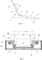
- the path of the light rays 14 is in Figure 5 to be seen as an example.
- the light coming from a light source, an LED 13, is coupled into the light guide 2 by collimators 2a.
- the collimators 2a are arranged along the ring of the light guide 2 as tooth-like structures.
- the term ring is broadly defined and also describes non-circular structures such as ellipses or free forms that extend like a frame around the inner lens.
- Each of the tooth-like structures absorbs the light from a respective assigned LED 13.
- the collimated light spreads out as a light beam 14 through the light guide 2 and is reflected by the respective side walls of the light guide 2 with total reflection to the output of the light guide 2 with the output surface 2b.
- the light guide 2 has a bend 2c at least at one point in order to bring the light rays into the desired angle to the output surface 2b.
- the light rays 14 should, if possible, be guided to the exit surface 2b of the light guide 2 with a single total reflection in order to minimize losses.
- the output surface 2b of the light guide 2 is designed so that the light is directed at an acute angle onto the input surface 10 of the inner lens 5.
- An air gap 9 is present between the input surface 10 of the inner lens 5 and the output surface 2b of the light guide 2, which runs obliquely to the input surface 10 of the inner lens 5.
- the air gap 9 is an annular gap between the annular light guide 2 and the inner lens 5.
- the light emerging from the light guide passes through the air gap 9 between the light guide 2 and the inner lens 5.
- the size of the air gap 9 must be precisely maintained over the entire ring structure in order to obtain the desired photometric performance.
- the light in the multilayer lens which consists of the inner lens 5 and the outer lens 6, moves between the two reflective films, the inner film 8 and the outer film 6, which reflect the light with a Lambertian distribution.
- the light beam reaches an opening 12 in the outer film 7, it enters the transparent cover layer 3 as seen from the outer lens 6 and exits the radome cover 1.
- Figure 6 shows the optical assembly 20 in an exemplary embodiment.
- the radome cover 1 already described is installed in a housing 15 that encloses it.
- holders 21 are attached to the inner lens 5.
- the non-reflective, non-transparent material of the holder 21 should not influence the light path.
- the housing 15 is attached to the bracket 21, whereby a seal 19, an adhesive connection, a plug-in system and/or a screw connection can be used here.
- the housing 15 serves to connect the ring-shaped PCB 16 on which the LEDs 13 are located, whereby the ring of the LEDs 13 has the diameter d2.
- This diameter d2 is larger than the diameter d1 of the inner lens 5, but smaller than the diameter d of the outer lens 6.
- the light guide 2 and the PCB are attached to the housing 15 via screws 18.
- the conical, ring-shaped light guide 2 has fastening lugs 22, which extend outwards perpendicular to the toothed edge.
- the ring-shaped housing 15 offers a central receptacle for a radar sensor 17, as shown in the Figure 6 is indicated by dashed lines.
- the shape and connection of the housing is an example; the housing walls 15a can be represented by other components of the vehicle, or can also be located further away from the radome cover.
- the housing 15 can also include other optical components for the outer paneling of a vehicle.
- the optical assembly is prefabricated during production and installed as a component, for example in the front module of the vehicle. This eliminates the need for screwing and gluing optical components directly when installing them in the front module.
Landscapes
- Engineering & Computer Science (AREA)
- Radar, Positioning & Navigation (AREA)
- Remote Sensing (AREA)
- Physics & Mathematics (AREA)
- Computer Networks & Wireless Communication (AREA)
- General Physics & Mathematics (AREA)
- Computer Security & Cryptography (AREA)
- Electromagnetism (AREA)
- Lighting Device Outwards From Vehicle And Optical Signal (AREA)
- Details Of Aerials (AREA)
Abstract
Optische Baugruppe (20) bestehend aus einem Gehäuse (15) mit einer Freisparung für einen Radarsensor, mit mindestens einem PCB (16) mit LEDs (13) bestückt und einer Radomabdeckung (1) mit einem Lichtleiter (2) und einer Anordnung von Linsen (6) und Folien (7,8), wobei der Lichtleiter (2) als ein einteiliger ringförmiger Konus ausgeführt ist, der mit einer Anbindung im Gehäuse (15) befestigt ist und dessen Ausgangsfläche (2b) mit einem Luftspalt von der Anordnung der Linsen (6) und Folien (7,8) beabstandet ist.
Description
- Die Erfindung betrifft eine optische Baugruppe mit einer beleuchteten Radomabdeckung für eine Öffnung eines Fahrzeugs und ein Verfahren zum Herstellen eines Fahrzeugbauteils mit einer optischen Baugruppe.
- In einer Karosserie bzw. Außenwandung eines Fahrzeugs sind regelmäßig funktionelle Elemente, wie bspw. Sensoren und dergleichen, anzuordnen. Zum Schutz dieser funktionellen Elemente, sowie aus ästhetischen Gründen kann des Weiteren vorgesehen sein, derartige Öffnungen für die funktionellen Elemente mit geeigneten Abdeckelementen abzudecken oder zu verschließen.
- Marken-Embleme für Kraftfahrzeuge werden häufig an der Vorderseite eines Fahrzeugs angebracht. Ihre Positionen am Frontmodul sind optimal für nach vorne gerichtete Radarsensoren geeignet.
- Ein Wunsch der Hersteller ist dabei, dass Embleme und Frontplatten dekorative Beleuchtungsfunktionen wie Positionslichter erhalten. Eine Kombination aus einem beleuchteten Emblem und einer Radarabdeckung muss sowohl die Anforderungen an die Beleuchtung als auch an die Radarleistung erfüllen.
- Die Transparenz für Radarwellen im 76,5-GHz-Band erfordert geringe Absorption, minimierte Reflexion und optimierte Transmission sowie eine konstante Bauteildicke ohne elektronische Komponenten im Sichtfeld des Radarsensors. Um Bereiche direkt im Strahlengang des Radarsensors zu beleuchten, ist es daher notwendig, Licht von der Außenseite des Radarbereichs in dessen Zentrum zu leiten.
- Diese Funktion wird von der Lichtleiteranordnung der Radarabdeckung erfüllt.
-
DE 10 2015 220 346 A1 zeigt betrifft ein Radom mit einer im Wesentlichen flächigen Frontplatte, welche frontseitig durchscheinend ausgebildet ist und welche rückseitig mit einer lichtundurchlässigen Schicht versehen ist, wobei in der lichtundurchlässigen Schicht zumindest eine Aussparung als Lichtdurchtritt ausgebildet ist, mit einem reflektierenden Bereich der flächigen Frontplatte, wobei der reflektierende Bereich der Aussparung benachbart angeordnet ist, mit zumindest einem im Wesentlichen flächigen Lichtleiter, welcher rückseitig an der lichtundurchlässigen Schicht angeordnet ist und mit zumindest einem Leuchtelement, welches mit dem Lichtleiter derart gekoppelt ist, so dass Licht in den Lichtleiter eintritt und so dass das Licht sich durch den zumindest einen Lichtleiter ausbreitet. An dem Lichtleiter ist ein Diffusorelement angeordnet, so dass sich durch den Lichtleiter ausbreitende Licht in das Diffusorelement eintritt, und durch das Diffusorelement ausbreitet und aus dem Diffusorelement austritt und an dem zumindest einen Lichtdurchtritt in die durchscheinende Frontplatte eintritt und gegebenenfalls an dem reflektierenden Bereich reflektiert wird, so dass es frontseitig aus der Frontplatte austritt, wobei das Diffusorelement eine modulierte Ausdehnung aufweist. - Bei der Herstellung der Radomabdeckung wurde ein Lichtleiterring, auf dem die Leiterplatten und die entsprechenden LEDs montiert sind, auf eine Lichtleitschicht der Radomabdeckung geklebt. Der Lichtleiterring wird durch Spritzgießen getrennt von der Lichtleitschicht gespritzt und anschließend montiert.
- Aus der
DE 10 2021 204 629 A1 ist ein Abdeckelement mit einem Gehäuse einer zwischen einer Frontplatte und einer Trägerplatte eingeformten und eingespritzten Folie bekannt, die zur Darstellung von mehrdimensionalen Strukturen dient, wobei die Trägerplatte rückseitig mit einer Heizplatte verbunden ist, und das Gehäuse aus einer ringförmigen Gehäusebasis und einer ringförmigen Gehäusefront besteht, und in der Gehäusebasis ein Leiterplattenring mit LEDs und Stecker eingebaut ist. -
JP 2019-217 863 A -
JP 2020-194 710 A -
JP 2021-027 005 A - Es ist Aufgabe der Erfindung, Schritte in der Herstellung des zentralen Lichtleiterrings zu beseitigen und die Montage- und Logistikkosten durch ein bereits vorgefertigte beleuchtete Radomabdeckung zu reduzieren.
- Die Aufgabe wird gelöst mit einer optischen Baugruppe bestehend aus einem Gehäuse mit einer Aufnahme für einen Radarsensor, mit mindestens einem PCB mit LEDs bestückt und einer Radomabdeckung mit einem Lichtleiter und einer Anordnung von Linsen und Folien, wobei der Lichtleiter als ein einteiliger ringförmiger Konus ausgeführt ist, der mit einer Anbindung im Gehäuse befestigt ist und dessen Ausgangsfläche mit einem Luftspalt von der Anordnung der Linsen und Folien beabstandet ist.
- Diese Anordnung erlaubt ein homogenes beleuchtetes Erscheinungsbild eines Emblems.
- Die optische Baugruppe ist so ausgestaltet, dass der ringförmige Konus des Lichtleiters sich vom Durchmesser eines oberen Rand zum Durchmesser der inneren Linse verjüngt.
- Es ist von Vorteil, wenn der obere Rand des Lichtleiters als gezahnte Struktur als Kollimator für das Licht der LEDs ausgebildet ist.
- Der Luftspalt zwischen der schräg angeordneten Ausgangsfläche des Lichtleiter und der im spitzen Winkel dazu angeordneten Eingangsfläche der inneren Linse beträgt 0,5mm bis 4,0mm, bevorzugt 2,5mm bis 3,5 mm.
- Der Lichtleiter weist Befestigungsfahnen auf, die senkrecht zur oberen Kante des Lichtleiters verlaufen.
- Die Radomabdeckung weist einen Aufbau mit einer äußeren transparenten Deckschicht, einer äußeren Folie, einer äußeren Linse, einer inneren Linse und einer inneren Folie auf.
- Die innere Linse weist eine Halterung für das Gehäuse auf.
- Die Halterung sowie die Anbindung an das Gehäuse erfolgt über Dichtungen, Klebungen, Verschraubungen oder Verklipsungen.
- Weitere optische Baugruppen können in einem vergrößerten Gehäuse angeordnet sein.
- Die Aufgabe wird auch gelöst mit einem Verfahren zur Herstellung eines Verkleidungsteils eines Fahrzeugs, das ein Radom enthält, wobei eine optische
- Baugruppe hergestellt wird und in ein Kunststoff-Bauteil in einer Ausnehmung als Ganzes befestigt wird.
-
-
Figur 1 zeigt ein Schnittbild der Radomabdeckung, -
Figur 2 zeigt eine Ansicht schräg von vorne auf die Abdeckung, -
Figur 3 zeigt eine Aufsicht auf die Abdeckung, -
Figur 4 zeigt einen Schnitt entlang der Linie A-A -
Figur 5 zeigt eine Vergrößerung des Schnittbilds derFigur 4 , -
Figur 6 zeigt eine beispielhafte optische Baugruppe. -
Figur 1 zeigt eine beleuchtete Radomabdeckung 1, die Teil einer optischen Baugruppe 20 ist. Die Radomabdeckung 1 besteht aus Linsen und Folien, wobei zur optischen Baugruppe 20 noch elektronische Komponenten, Befestigungen und Gehäuse dazukommen. - Eine transparente Deckschicht 3 begrenzt die optische Baugruppe 20 zur Fahrzeugaußenseite hin. Ein Lichtleiter 2 ist als ringförmiger Kranz ausgebildet, wobei sich der Kranz von den Kollimatorstellen 2a zur transparenten Deckschicht 3 hin verjüngt.
- In
Figur 2 ist in der Aufsicht noch zusätzlich schematisch dargestellt, dass ein Emblem 4 durch die transparente Deckschicht 3 scheinen kann. Der gestrichelte Kreis deutet die Lage einer inneren Linse 5, wie auch inFigur 3 , an. - Die
Figuren 4 und5 sind Schnittbilder der Radomabdeckung 1 entlang der Schnittlinie A-A derFigur 3 . - Auf die transparente Deckschicht 3 folgt eine äußere Folie 7, deren Vorderseite, die durch die transparente Deckschicht 3 vom Äußeren des Fahrzeugs aus sichtbar ist, dekorativ, z. B. in Wagenfarbe, gestaltet ist. Auf der Rückseite der äu-ßeren Folie 7 ist eine lichtreflektierende Schicht aufgebracht. Die äußere Folie 7 ist von Öffnungen 12 durchbrochen, in ihrer Gesamtheit ein Muster, beispielsweise ein Emblem 4 darstellen.
- Eine äußere Linse 6 schützt die äußere Folie 7 und besteht aus einem Standard-Schutzplastikmaterial. Sowohl die äußere Folie 7 als auch die äußere Linse 6 weisen denselben Durchmesser d, bzw. dieselbe Außenkontur wie die transparente Abdeckung 3 auf.
- Auf der äußeren Linse 6 ist eine innere Linse 5 aus Kunststoff mit geringem Absorptionskoeffizienten für die Lichtverteilung aufgebracht. Die innere Linse 5 weist einen geringeren Durchmesser d1, geringere Außenkontur als die transparente Deckschicht 3 auf.
- Die innere Linse 5 ist zum Fahrzeuginneren hin mit einer inneren Folie 8 versehen, die auf der Vorderseite zur inneren Linse 5 hin reflektierend und auf der Rückseite zum Fahrzeuginneren hin absorbierend für das eingekoppelte Licht ist.
- Der Weg der Lichtstrahlen 14 ist in
Figur 5 beispielhaft zu sehen. - Das von einer Lichtquelle, einer LED 13, kommende Licht wird durch Kollimatoren 2a in den Lichtleiter 2 eingekoppelt. Die Kollimatoren 2a sind dabei entlang des Rings des Lichtleiters 2 als zahnartige Strukturen angeordnet. Der Begriff Ring ist dabei weit gefasst und beschreibt auch nicht kreisrunde Strukturen wie Ellipsen, oder Freiformen, die sich rahmenartig um die innere Linse erstrecken. Jede der zahnartigen Strukturen nimmt das Licht einer jeweilig zugeordneten LED 13 auf. Das kollimierte Licht breitet sich als Lichtstrahl 14 durch den Lichtleiter 2 aus und wird von den jeweiligen Seitenwänden des Lichtleiters 2 mit Totalreflektion zum Ausgang des Lichtleiters 2 mit der Ausgangsfläche 2b reflektiert. Der Lichtleiter 2 weist dabei mindestens an einer Stelle einen Verlaufsknick 2c auf, um die Lichtstrahlen in den gewünschten Winkel zur Ausgangsfläche 2b zu bringen.
- Die Lichtstrahlen 14 sollen dabei möglichst mit einer einzigen Totalreflexion auf die Austrittsfläche 2b des Lichtleiters 2 geleitet werden, um Verluste zu minimieren.
- Die Ausgangsfläche 2b des Lichtleiters 2 ist so gestaltet, dass das Licht in einem spitzen Winkel auf die Eingangsfläche 10 der innere Linse 5 gerichtet ist. Zwischen der Eingangsfläche 10 der inneren Linse 5 und der Ausgangsfläche 2b des Lichtleiters 2, die schräg zur Eingangsfläche 10 der inneren Linse 5 verläuft, ist ein Luftspalt 9 vorhanden. Der Luftspalt 9 ist ein Ringspalt zwischen dem ringförmigen Lichtleiter 2 und der inneren Linse 5.
- Das aus dem Lichtleiter austretende Licht durchquert den Luftspalt 9 zwischen dem Lichtleiter 2 und der inneren Linse 5. Die Größe des Luftspalts 9 muss dabei über die gesamte Ringstruktur exakt eingehalten werden, um die gewünschte fotometrische Leistung zu erhalten.
- Das Licht in der Mehrschichtlinse, die sich aus der inneren Linse 5 und der äußeren Linse 6 zusammensetzt, bewegt sich zwischen den zwei Reflexionsfolien, der inneren Folie 8 und der äußeren Folie 6, die das Licht mit einer Lambert-Verteilung reflektieren. Wenn der Lichtstrahl eine Öffnung 12 in der äußeren Folie 7 erreicht, tritt er von der äußeren Linse 6 aus gesehen in die transparente Deckschicht 3 und verlässt die Radomabdeckung 1.
-
Figur 6 zeigt die optische Baugruppe 20 in einem Ausführungsbeispiel. Die bereits beschriebene Radomabdeckung 1 ist in einem sie umschließenden Gehäuse 15 verbaut. Dazu werden Halterungen 21 auf der inneren Linse 5 angebracht. Das nicht reflektierende, nicht transparente Material der Halterung 21 soll den Lichtweg nicht beeinflussen. - An der Halterung 21 wird das Gehäuse 15 befestigt, wobei hier eine Dichtung 19, eine Klebeverbindung, ein Stecksystem und/oder eine Verschraubung eingesetzt werden kann.
- Das Gehäuse 15 dient zur Anbindung des ringförmigen PCBs 16, auf dem die LEDs 13 sitzen, wobei der Ring der LEDs 13 den Durchmesser d2 aufweist. Dieser Durchmesser d2 ist größer als der Durchmesser d1 der inneren Linse 5, aber kleiner als der Durchmesser d der äußeren Linse 6.
- Über Schrauben 18 sind der Lichtleiter 2 und das PCB am Gehäuse 15 befestigt. Dazu weist der konische, ringförmige Lichtleiter 2 Befestigungsfahnen 22 auf, die sich senkrecht zum gezahnten Rand jeweils nach außen erstrecken. Das ringförmige Gehäuse 15 bietet zentral eine Aufnahme für einen Radarsensor 17, wie er in der
Figur 6 gestrichelt angedeutet ist. - Die Form und die Anbindung des Gehäuses ist ein Beispiel, die Gehäusewände 15a können durch weitere Bauteile des Fahrzeugs dargestellt sein, oder auch weiter entfernt von der Radomabdeckung liegen. Das Gehäuse 15 kann auch noch weitere optische Baugruppen für die Außenverkleidung eines Fahrzeugs umfassen.
- Die optische Baugruppe wird in der Herstellung vorgefertigt und als ein Bauteil beispielsweise im Frontmodul des Fahrzeugs verbaut. Dadurch entfallen Verschraubungen und Klebungen an optischen Bauteilen direkt beim Verbau in das Frontmodul.
-
- 1 Radomabdeckung
- 2 Lichtleiter
- 2a Kollimator
- 2b Austrittsfläche Lichtleiter
- 2c Verlaufsknick
- 3 Transparente Deckschicht
- 4 Emblem
- 5 innerer Linse
- 6 äußere Linse
- 7 äußere Folie
- 8 innerer Folie
- 9 Luftspalt
- 10 Eingangsfläche innere Linse
- 11 Verbindung innere und äußere Linse
- 12 Öffnungen
- 13 LED
- 14 Lichtstrahlen
- 15 Gehäuse
- 16 PCB
- 17 Radarsensor
- 18 Schraube
- 19 Dichtung
- 20 optische Baugruppe
- 21 Halterung
- 22 Befestigungsfahne
Claims (9)
- Optische Baugruppe (20) bestehend aus einem Gehäuse (15) mit einer Aufnahme für einen Radarsensor (17), mit mindestens einem PCB (16) mit LEDs (13) bestückt und einer Radomabdeckung (1) mit einem Lichtleiter (2) und einer Anordnung von Linsen, mit einer inneren Linse (5) und einer äu-ßeren Linse (6), und Folien (7,8), wobei der Lichtleiter (2) als ein einteiliger ringförmiger Konus ausgeführt ist, der mit einer Anbindung im Gehäuse (15) befestigt ist und dessen Ausgangsfläche mit einem Luftspalt (9) von der Anordnung der Linsen und Folien beabstandet ist, dadurch gekennzeichnet, dass der Lichtleiter Befestigungsfahnen (11) aufweist, die senkrecht zur oberen Kante des Lichtleiters (2) verlaufen und die sich senkrecht zum Rand jeweils nach außen erstrecken, und das Gehäuse (15) zur Anbindung des ringförmigen PCBs (16) dient, auf dem die LEDs (13) sitzen, wobei der Ring der LEDs (13) einen Durchmesser d2 aufweist, der größer ist als der Durchmesser d1 der inneren Linse (5), aber kleiner als der Durchmesser d der äußeren Linse (6).
- Optische Baugruppe (20) nach Anspruch 1, dadurch gekennzeichnet, dass der ringförmige Konus des Lichtleiters (2) sich vom Durchmesser eines oberen Randes zum Durchmesser der inneren Linse (5) verjüngt.
- Optische Baugruppe nach Anspruch 1 oder 2, dadurch gekennzeichnet, dass der obere Rand des Lichtleiters (2) als gezahnte Struktur als Kollimator für das Licht der LEDs (13) ausgebildet ist.
- Optische Baugruppe nach einem der vorhergehenden Ansprüche, dadurch gekennzeichnet, dass der Luftspalt (9) zwischen der schräg angeordneten Ausgangsfläche des Lichtleiter und der im spitzen Winkel dazu angeordneten Eingangsfläche (10) der inneren Linse (5) 0,5mm bis 4,0mm, bevorzugt 2,5 mm bis 3,5 mm beträgt.
- Optische Baugruppe (20) nach einem der vorhergehenden Ansprüche,
dadurch gekennzeichnet, dass die Radomabdeckung (1) einen Aufbau mit einer äußeren transparenten Deckschicht (3), einer äußeren Folie (7), einer äußeren Linse (6), einer inneren Linse (5) und einer inneren Folie (8) aufweist. - Optische Baugruppe (20) nach einem der vorhergehenden Ansprüche,
dadurch gekennzeichnet, dass die innere Linse (5) eine Halterung (21) für das Gehäuse aufweist. - Optische Baugruppe (20) nach einem der vorhergehenden Ansprüche,
dadurch gekennzeichnet, dass die Halterung (21) sowie die Anbindung an das Gehäuse (15) über Dichtungen, Klebungen, Verschraubungen und/oder Verklipsungen erfolgt. - Optische Baugruppe (20) nach einem der vorhergehenden Ansprüche,
dadurch gekennzeichnet, dass weitere optische Baugruppen in einem vergrößerten Gehäuse angeordnet sind. - Verfahren zur Herstellung eines Verkleidungsteils eines Fahrzeugs, das ein Radom enthält, wobei eine optische Baugruppe (20) nach einem der vorhergehen Ansprüche hergestellt wird und in ein Kunststoff-Bauteil in einer Ausnehmung als Ganzes befestigt wird.
Applications Claiming Priority (1)
| Application Number | Priority Date | Filing Date | Title |
|---|---|---|---|
| DE102023206762.5A DE102023206762A1 (de) | 2023-07-17 | 2023-07-17 | Optische Baugruppe und Herstellen eines Fahrzeugbauteils mit optischer Baugruppe |
Publications (1)
| Publication Number | Publication Date |
|---|---|
| EP4495618A1 true EP4495618A1 (de) | 2025-01-22 |
Family
ID=91782219
Family Applications (1)
| Application Number | Title | Priority Date | Filing Date |
|---|---|---|---|
| EP24186065.9A Pending EP4495618A1 (de) | 2023-07-17 | 2024-07-02 | Optische baugruppe und herstellen eines fahrzeugbauteils mit optischer baugruppe |
Country Status (2)
| Country | Link |
|---|---|
| EP (1) | EP4495618A1 (de) |
| DE (1) | DE102023206762A1 (de) |
Citations (5)
| Publication number | Priority date | Publication date | Assignee | Title |
|---|---|---|---|---|
| DE102015220346A1 (de) | 2015-10-19 | 2017-04-20 | Hella Kgaa Hueck & Co. | Radom |
| JP2019217863A (ja) | 2018-06-19 | 2019-12-26 | サカエ理研工業株式会社 | 発光表示装置 |
| JP2020194710A (ja) | 2019-05-29 | 2020-12-03 | 本田技研工業株式会社 | 車両用灯体 |
| JP2021027005A (ja) | 2019-08-08 | 2021-02-22 | パナソニックIpマネジメント株式会社 | 光学システム、照明システム、表示システム及び移動体 |
| DE102021204629A1 (de) | 2021-05-06 | 2022-11-10 | Magna Exteriors Gmbh | Abdeckelement für Sensoren, sowie Verfahren zur Herstellung des Abdeckelements |
-
2023
- 2023-07-17 DE DE102023206762.5A patent/DE102023206762A1/de active Pending
-
2024
- 2024-07-02 EP EP24186065.9A patent/EP4495618A1/de active Pending
Patent Citations (6)
| Publication number | Priority date | Publication date | Assignee | Title |
|---|---|---|---|---|
| DE102015220346A1 (de) | 2015-10-19 | 2017-04-20 | Hella Kgaa Hueck & Co. | Radom |
| JP2019217863A (ja) | 2018-06-19 | 2019-12-26 | サカエ理研工業株式会社 | 発光表示装置 |
| JP2020194710A (ja) | 2019-05-29 | 2020-12-03 | 本田技研工業株式会社 | 車両用灯体 |
| JP2021027005A (ja) | 2019-08-08 | 2021-02-22 | パナソニックIpマネジメント株式会社 | 光学システム、照明システム、表示システム及び移動体 |
| DE102021204629A1 (de) | 2021-05-06 | 2022-11-10 | Magna Exteriors Gmbh | Abdeckelement für Sensoren, sowie Verfahren zur Herstellung des Abdeckelements |
| DE102021204629B4 (de) * | 2021-05-06 | 2023-07-13 | Magna Exteriors Gmbh | Abdeckelement für Sensoren, sowie Verfahren zur Herstellung des Abdeckelements |
Also Published As
| Publication number | Publication date |
|---|---|
| DE102023206762A1 (de) | 2025-01-23 |
Similar Documents
| Publication | Publication Date | Title |
|---|---|---|
| DE102017123669B4 (de) | Leuchtvorrichtung | |
| DE102015013669B4 (de) | Hinterleuchtetes Innenausstattungsteil für ein Kraftfahrzeug | |
| EP3844028B1 (de) | Beleuchtungsvorrichtung für ein kraftfahrzeug | |
| DE102006048323A1 (de) | Außenrückblickspiegel für Fahrzeuge, vorzugsweise für Kraftfahrzeuge | |
| EP1141623B1 (de) | Lichtquellenelement mit seitlicher schräger lichteinkopplung | |
| EP2322962A1 (de) | Dekorelement mit einem Lichtleiter | |
| DE102017102244B4 (de) | Beleuchtete fensterbaugruppen und verfahren zur herstellung derselben | |
| DE102012101434B4 (de) | Linsenhalter zur Aufnahme einer Linse in einem Scheinwerfer | |
| DE102017217507A1 (de) | Beleuchtbares Emblem | |
| DE102008056985A1 (de) | Zierleuchteneinheit für Fahrzeuge | |
| WO2024088849A1 (de) | Fahrzeugscheibe mit lichtquelle und lichtleiterschicht | |
| DE102006035842B9 (de) | Fahrzeugleuchte mit einer einstückigen Lichtleiter-Blenden-Einheit | |
| DE102007033706B4 (de) | Fahrzeugleuchtvorrichtung mit einer dreidimensionalen mehrfarbigen Zwischenlichtscheibe | |
| EP3336416B1 (de) | Beleuchtungseinheit | |
| DE102013007856A1 (de) | Lichtleitkörper und Leuchtvorrichtung mit dem Lichtleitkörper | |
| EP3792111B1 (de) | Leuchte | |
| DE102023122482A1 (de) | Beleuchtungseinrichtung, insbesondere für ein Kraftfahrzeug | |
| DE2939329A1 (de) | Signalleuchte, insbesondere blinkleuchte fuer kraftfahrzeuge | |
| DE102011104055A1 (de) | Leuchteinrichtung für ein Fahrzeug | |
| EP3853518B1 (de) | Lichtmodul, insbesondere zur verwendung in einer beleuchtungsvorrichtung für ein kraftfahrzeug | |
| DE102023206762A1 (de) | Optische Baugruppe und Herstellen eines Fahrzeugbauteils mit optischer Baugruppe | |
| EP3027458B1 (de) | Beleuchtung für eine instrumententafel eines fahrzeugs | |
| DE102020201645A1 (de) | Beleuchtungsvorrichtung für ein Kraftfahrzeug | |
| DE102017000805A1 (de) | Kraftfahrzeugleuchte sowie Kraftfahrzeug | |
| EP2500629B1 (de) | Aussenspiegel eines Fahrzeugs mit Beleuchtungseinheit samt Mikrooptiken |
Legal Events
| Date | Code | Title | Description |
|---|---|---|---|
| PUAI | Public reference made under article 153(3) epc to a published international application that has entered the european phase |
Free format text: ORIGINAL CODE: 0009012 |
|
| STAA | Information on the status of an ep patent application or granted ep patent |
Free format text: STATUS: THE APPLICATION HAS BEEN PUBLISHED |
|
| STAA | Information on the status of an ep patent application or granted ep patent |
Free format text: STATUS: REQUEST FOR EXAMINATION WAS MADE |
|
| AK | Designated contracting states |
Kind code of ref document: A1 Designated state(s): AL AT BE BG CH CY CZ DE DK EE ES FI FR GB GR HR HU IE IS IT LI LT LU LV MC ME MK MT NL NO PL PT RO RS SE SI SK SM TR |
|
| 17P | Request for examination filed |
Effective date: 20250110 |