EP4495461A1 - Ventilvorrichtung - Google Patents
Ventilvorrichtung Download PDFInfo
- Publication number
- EP4495461A1 EP4495461A1 EP23770589.2A EP23770589A EP4495461A1 EP 4495461 A1 EP4495461 A1 EP 4495461A1 EP 23770589 A EP23770589 A EP 23770589A EP 4495461 A1 EP4495461 A1 EP 4495461A1
- Authority
- EP
- European Patent Office
- Prior art keywords
- rotor
- seal
- flow path
- circumferential surface
- valve member
- Prior art date
- Legal status (The legal status is an assumption and is not a legal conclusion. Google has not performed a legal analysis and makes no representation as to the accuracy of the status listed.)
- Pending
Links
Images







Classifications
-
- F—MECHANICAL ENGINEERING; LIGHTING; HEATING; WEAPONS; BLASTING
- F16—ENGINEERING ELEMENTS AND UNITS; GENERAL MEASURES FOR PRODUCING AND MAINTAINING EFFECTIVE FUNCTIONING OF MACHINES OR INSTALLATIONS; THERMAL INSULATION IN GENERAL
- F16K—VALVES; TAPS; COCKS; ACTUATING-FLOATS; DEVICES FOR VENTING OR AERATING
- F16K39/00—Devices for relieving the pressure on the sealing faces
- F16K39/06—Devices for relieving the pressure on the sealing faces for taps or cocks
-
- F—MECHANICAL ENGINEERING; LIGHTING; HEATING; WEAPONS; BLASTING
- F16—ENGINEERING ELEMENTS AND UNITS; GENERAL MEASURES FOR PRODUCING AND MAINTAINING EFFECTIVE FUNCTIONING OF MACHINES OR INSTALLATIONS; THERMAL INSULATION IN GENERAL
- F16K—VALVES; TAPS; COCKS; ACTUATING-FLOATS; DEVICES FOR VENTING OR AERATING
- F16K11/00—Multiple-way valves, e.g. mixing valves; Pipe fittings incorporating such valves
- F16K11/02—Multiple-way valves, e.g. mixing valves; Pipe fittings incorporating such valves with all movable sealing faces moving as one unit
- F16K11/08—Multiple-way valves, e.g. mixing valves; Pipe fittings incorporating such valves with all movable sealing faces moving as one unit comprising only taps or cocks
- F16K11/083—Multiple-way valves, e.g. mixing valves; Pipe fittings incorporating such valves with all movable sealing faces moving as one unit comprising only taps or cocks with tapered plug
-
- F—MECHANICAL ENGINEERING; LIGHTING; HEATING; WEAPONS; BLASTING
- F16—ENGINEERING ELEMENTS AND UNITS; GENERAL MEASURES FOR PRODUCING AND MAINTAINING EFFECTIVE FUNCTIONING OF MACHINES OR INSTALLATIONS; THERMAL INSULATION IN GENERAL
- F16K—VALVES; TAPS; COCKS; ACTUATING-FLOATS; DEVICES FOR VENTING OR AERATING
- F16K11/00—Multiple-way valves, e.g. mixing valves; Pipe fittings incorporating such valves
- F16K11/02—Multiple-way valves, e.g. mixing valves; Pipe fittings incorporating such valves with all movable sealing faces moving as one unit
- F16K11/08—Multiple-way valves, e.g. mixing valves; Pipe fittings incorporating such valves with all movable sealing faces moving as one unit comprising only taps or cocks
- F16K11/083—Multiple-way valves, e.g. mixing valves; Pipe fittings incorporating such valves with all movable sealing faces moving as one unit comprising only taps or cocks with tapered plug
- F16K11/0833—Multiple-way valves, e.g. mixing valves; Pipe fittings incorporating such valves with all movable sealing faces moving as one unit comprising only taps or cocks with tapered plug having all the connecting conduits situated in a single plane perpendicular to the axis of the plug
-
- F—MECHANICAL ENGINEERING; LIGHTING; HEATING; WEAPONS; BLASTING
- F16—ENGINEERING ELEMENTS AND UNITS; GENERAL MEASURES FOR PRODUCING AND MAINTAINING EFFECTIVE FUNCTIONING OF MACHINES OR INSTALLATIONS; THERMAL INSULATION IN GENERAL
- F16K—VALVES; TAPS; COCKS; ACTUATING-FLOATS; DEVICES FOR VENTING OR AERATING
- F16K11/00—Multiple-way valves, e.g. mixing valves; Pipe fittings incorporating such valves
- F16K11/02—Multiple-way valves, e.g. mixing valves; Pipe fittings incorporating such valves with all movable sealing faces moving as one unit
- F16K11/08—Multiple-way valves, e.g. mixing valves; Pipe fittings incorporating such valves with all movable sealing faces moving as one unit comprising only taps or cocks
- F16K11/085—Multiple-way valves, e.g. mixing valves; Pipe fittings incorporating such valves with all movable sealing faces moving as one unit comprising only taps or cocks with cylindrical plug
-
- F—MECHANICAL ENGINEERING; LIGHTING; HEATING; WEAPONS; BLASTING
- F16—ENGINEERING ELEMENTS AND UNITS; GENERAL MEASURES FOR PRODUCING AND MAINTAINING EFFECTIVE FUNCTIONING OF MACHINES OR INSTALLATIONS; THERMAL INSULATION IN GENERAL
- F16K—VALVES; TAPS; COCKS; ACTUATING-FLOATS; DEVICES FOR VENTING OR AERATING
- F16K11/00—Multiple-way valves, e.g. mixing valves; Pipe fittings incorporating such valves
- F16K11/02—Multiple-way valves, e.g. mixing valves; Pipe fittings incorporating such valves with all movable sealing faces moving as one unit
- F16K11/08—Multiple-way valves, e.g. mixing valves; Pipe fittings incorporating such valves with all movable sealing faces moving as one unit comprising only taps or cocks
- F16K11/085—Multiple-way valves, e.g. mixing valves; Pipe fittings incorporating such valves with all movable sealing faces moving as one unit comprising only taps or cocks with cylindrical plug
- F16K11/0856—Multiple-way valves, e.g. mixing valves; Pipe fittings incorporating such valves with all movable sealing faces moving as one unit comprising only taps or cocks with cylindrical plug having all the connecting conduits situated in more than one plane perpendicular to the axis of the plug
-
- F—MECHANICAL ENGINEERING; LIGHTING; HEATING; WEAPONS; BLASTING
- F16—ENGINEERING ELEMENTS AND UNITS; GENERAL MEASURES FOR PRODUCING AND MAINTAINING EFFECTIVE FUNCTIONING OF MACHINES OR INSTALLATIONS; THERMAL INSULATION IN GENERAL
- F16K—VALVES; TAPS; COCKS; ACTUATING-FLOATS; DEVICES FOR VENTING OR AERATING
- F16K5/00—Plug valves; Taps or cocks comprising only cut-off apparatus having at least one of the sealing faces shaped as a more or less complete surface of a solid of revolution, the opening and closing movement being predominantly rotary
- F16K5/02—Plug valves; Taps or cocks comprising only cut-off apparatus having at least one of the sealing faces shaped as a more or less complete surface of a solid of revolution, the opening and closing movement being predominantly rotary with plugs having conical surfaces; Packings therefor
- F16K5/0207—Plug valves; Taps or cocks comprising only cut-off apparatus having at least one of the sealing faces shaped as a more or less complete surface of a solid of revolution, the opening and closing movement being predominantly rotary with plugs having conical surfaces; Packings therefor with special plug arrangement, e.g. special shape or built in means
-
- F—MECHANICAL ENGINEERING; LIGHTING; HEATING; WEAPONS; BLASTING
- F16—ENGINEERING ELEMENTS AND UNITS; GENERAL MEASURES FOR PRODUCING AND MAINTAINING EFFECTIVE FUNCTIONING OF MACHINES OR INSTALLATIONS; THERMAL INSULATION IN GENERAL
- F16K—VALVES; TAPS; COCKS; ACTUATING-FLOATS; DEVICES FOR VENTING OR AERATING
- F16K5/00—Plug valves; Taps or cocks comprising only cut-off apparatus having at least one of the sealing faces shaped as a more or less complete surface of a solid of revolution, the opening and closing movement being predominantly rotary
- F16K5/02—Plug valves; Taps or cocks comprising only cut-off apparatus having at least one of the sealing faces shaped as a more or less complete surface of a solid of revolution, the opening and closing movement being predominantly rotary with plugs having conical surfaces; Packings therefor
- F16K5/0257—Packings
- F16K5/0271—Packings between housing and plug
-
- F—MECHANICAL ENGINEERING; LIGHTING; HEATING; WEAPONS; BLASTING
- F16—ENGINEERING ELEMENTS AND UNITS; GENERAL MEASURES FOR PRODUCING AND MAINTAINING EFFECTIVE FUNCTIONING OF MACHINES OR INSTALLATIONS; THERMAL INSULATION IN GENERAL
- F16K—VALVES; TAPS; COCKS; ACTUATING-FLOATS; DEVICES FOR VENTING OR AERATING
- F16K5/00—Plug valves; Taps or cocks comprising only cut-off apparatus having at least one of the sealing faces shaped as a more or less complete surface of a solid of revolution, the opening and closing movement being predominantly rotary
- F16K5/02—Plug valves; Taps or cocks comprising only cut-off apparatus having at least one of the sealing faces shaped as a more or less complete surface of a solid of revolution, the opening and closing movement being predominantly rotary with plugs having conical surfaces; Packings therefor
- F16K5/0257—Packings
- F16K5/0285—Packings spindle sealing
-
- F—MECHANICAL ENGINEERING; LIGHTING; HEATING; WEAPONS; BLASTING
- F16—ENGINEERING ELEMENTS AND UNITS; GENERAL MEASURES FOR PRODUCING AND MAINTAINING EFFECTIVE FUNCTIONING OF MACHINES OR INSTALLATIONS; THERMAL INSULATION IN GENERAL
- F16K—VALVES; TAPS; COCKS; ACTUATING-FLOATS; DEVICES FOR VENTING OR AERATING
- F16K5/00—Plug valves; Taps or cocks comprising only cut-off apparatus having at least one of the sealing faces shaped as a more or less complete surface of a solid of revolution, the opening and closing movement being predominantly rotary
- F16K5/04—Plug valves; Taps or cocks comprising only cut-off apparatus having at least one of the sealing faces shaped as a more or less complete surface of a solid of revolution, the opening and closing movement being predominantly rotary with plugs having cylindrical surfaces; Packings therefor
- F16K5/0407—Plug valves; Taps or cocks comprising only cut-off apparatus having at least one of the sealing faces shaped as a more or less complete surface of a solid of revolution, the opening and closing movement being predominantly rotary with plugs having cylindrical surfaces; Packings therefor with particular plug arrangements, e.g. particular shape or built-in means
-
- F—MECHANICAL ENGINEERING; LIGHTING; HEATING; WEAPONS; BLASTING
- F16—ENGINEERING ELEMENTS AND UNITS; GENERAL MEASURES FOR PRODUCING AND MAINTAINING EFFECTIVE FUNCTIONING OF MACHINES OR INSTALLATIONS; THERMAL INSULATION IN GENERAL
- F16K—VALVES; TAPS; COCKS; ACTUATING-FLOATS; DEVICES FOR VENTING OR AERATING
- F16K5/00—Plug valves; Taps or cocks comprising only cut-off apparatus having at least one of the sealing faces shaped as a more or less complete surface of a solid of revolution, the opening and closing movement being predominantly rotary
- F16K5/04—Plug valves; Taps or cocks comprising only cut-off apparatus having at least one of the sealing faces shaped as a more or less complete surface of a solid of revolution, the opening and closing movement being predominantly rotary with plugs having cylindrical surfaces; Packings therefor
- F16K5/0457—Packings
- F16K5/0471—Packings between housing and plug
-
- F—MECHANICAL ENGINEERING; LIGHTING; HEATING; WEAPONS; BLASTING
- F16—ENGINEERING ELEMENTS AND UNITS; GENERAL MEASURES FOR PRODUCING AND MAINTAINING EFFECTIVE FUNCTIONING OF MACHINES OR INSTALLATIONS; THERMAL INSULATION IN GENERAL
- F16K—VALVES; TAPS; COCKS; ACTUATING-FLOATS; DEVICES FOR VENTING OR AERATING
- F16K5/00—Plug valves; Taps or cocks comprising only cut-off apparatus having at least one of the sealing faces shaped as a more or less complete surface of a solid of revolution, the opening and closing movement being predominantly rotary
- F16K5/04—Plug valves; Taps or cocks comprising only cut-off apparatus having at least one of the sealing faces shaped as a more or less complete surface of a solid of revolution, the opening and closing movement being predominantly rotary with plugs having cylindrical surfaces; Packings therefor
- F16K5/0457—Packings
- F16K5/0485—Spindle sealing
-
- F—MECHANICAL ENGINEERING; LIGHTING; HEATING; WEAPONS; BLASTING
- F16—ENGINEERING ELEMENTS AND UNITS; GENERAL MEASURES FOR PRODUCING AND MAINTAINING EFFECTIVE FUNCTIONING OF MACHINES OR INSTALLATIONS; THERMAL INSULATION IN GENERAL
- F16K—VALVES; TAPS; COCKS; ACTUATING-FLOATS; DEVICES FOR VENTING OR AERATING
- F16K5/00—Plug valves; Taps or cocks comprising only cut-off apparatus having at least one of the sealing faces shaped as a more or less complete surface of a solid of revolution, the opening and closing movement being predominantly rotary
- F16K5/08—Details
- F16K5/14—Special arrangements for separating the sealing faces or for pressing them together
- F16K5/16—Special arrangements for separating the sealing faces or for pressing them together for plugs with conical surfaces
- F16K5/162—Special arrangements for separating the sealing faces or for pressing them together for plugs with conical surfaces with the plugs or parts of the plugs mechanically pressing the seal against the housing
- F16K5/163—Special arrangements for separating the sealing faces or for pressing them together for plugs with conical surfaces with the plugs or parts of the plugs mechanically pressing the seal against the housing adjustable in height
-
- F—MECHANICAL ENGINEERING; LIGHTING; HEATING; WEAPONS; BLASTING
- F16—ENGINEERING ELEMENTS AND UNITS; GENERAL MEASURES FOR PRODUCING AND MAINTAINING EFFECTIVE FUNCTIONING OF MACHINES OR INSTALLATIONS; THERMAL INSULATION IN GENERAL
- F16K—VALVES; TAPS; COCKS; ACTUATING-FLOATS; DEVICES FOR VENTING OR AERATING
- F16K5/00—Plug valves; Taps or cocks comprising only cut-off apparatus having at least one of the sealing faces shaped as a more or less complete surface of a solid of revolution, the opening and closing movement being predominantly rotary
- F16K5/08—Details
- F16K5/14—Special arrangements for separating the sealing faces or for pressing them together
- F16K5/16—Special arrangements for separating the sealing faces or for pressing them together for plugs with conical surfaces
- F16K5/162—Special arrangements for separating the sealing faces or for pressing them together for plugs with conical surfaces with the plugs or parts of the plugs mechanically pressing the seal against the housing
- F16K5/165—Means pressing on the small diameter
-
- F—MECHANICAL ENGINEERING; LIGHTING; HEATING; WEAPONS; BLASTING
- F16—ENGINEERING ELEMENTS AND UNITS; GENERAL MEASURES FOR PRODUCING AND MAINTAINING EFFECTIVE FUNCTIONING OF MACHINES OR INSTALLATIONS; THERMAL INSULATION IN GENERAL
- F16K—VALVES; TAPS; COCKS; ACTUATING-FLOATS; DEVICES FOR VENTING OR AERATING
- F16K5/00—Plug valves; Taps or cocks comprising only cut-off apparatus having at least one of the sealing faces shaped as a more or less complete surface of a solid of revolution, the opening and closing movement being predominantly rotary
- F16K5/08—Details
- F16K5/14—Special arrangements for separating the sealing faces or for pressing them together
- F16K5/16—Special arrangements for separating the sealing faces or for pressing them together for plugs with conical surfaces
- F16K5/162—Special arrangements for separating the sealing faces or for pressing them together for plugs with conical surfaces with the plugs or parts of the plugs mechanically pressing the seal against the housing
- F16K5/166—Means pressing on the large diameter
-
- F—MECHANICAL ENGINEERING; LIGHTING; HEATING; WEAPONS; BLASTING
- F16—ENGINEERING ELEMENTS AND UNITS; GENERAL MEASURES FOR PRODUCING AND MAINTAINING EFFECTIVE FUNCTIONING OF MACHINES OR INSTALLATIONS; THERMAL INSULATION IN GENERAL
- F16K—VALVES; TAPS; COCKS; ACTUATING-FLOATS; DEVICES FOR VENTING OR AERATING
- F16K5/00—Plug valves; Taps or cocks comprising only cut-off apparatus having at least one of the sealing faces shaped as a more or less complete surface of a solid of revolution, the opening and closing movement being predominantly rotary
- F16K5/08—Details
- F16K5/14—Special arrangements for separating the sealing faces or for pressing them together
- F16K5/16—Special arrangements for separating the sealing faces or for pressing them together for plugs with conical surfaces
- F16K5/168—Sealing effected by the flowing medium
-
- F—MECHANICAL ENGINEERING; LIGHTING; HEATING; WEAPONS; BLASTING
- F16—ENGINEERING ELEMENTS AND UNITS; GENERAL MEASURES FOR PRODUCING AND MAINTAINING EFFECTIVE FUNCTIONING OF MACHINES OR INSTALLATIONS; THERMAL INSULATION IN GENERAL
- F16K—VALVES; TAPS; COCKS; ACTUATING-FLOATS; DEVICES FOR VENTING OR AERATING
- F16K5/00—Plug valves; Taps or cocks comprising only cut-off apparatus having at least one of the sealing faces shaped as a more or less complete surface of a solid of revolution, the opening and closing movement being predominantly rotary
- F16K5/08—Details
- F16K5/14—Special arrangements for separating the sealing faces or for pressing them together
- F16K5/18—Special arrangements for separating the sealing faces or for pressing them together for plugs with cylindrical surfaces
- F16K5/188—Sealing effected by the flowing medium
Definitions
- the present invention relates to a valve device for controlling a liquid.
- Patent Document 1 discloses a switching valve comprising a rotatable shaft, a valve body connected to one end of the shaft, and a main body for accommodating the valve body.
- Patent Document 1 Japanese Patent Application, Laid-Open Publication 2013-92176
- an object of one aspect of the present invention is to suppress or prevent pressure buildup in a space between a rotatable valve member and a housing.
- a valve device is a valve device for controlling a coolant used in an automobile, the valve device including: a valve member that includes a shaft portion rotatable about a rotation axis, and a rotor connected to an end of the shaft portion, the end of the shaft portion being an end in a first direction along the rotation axis, and in which on an outer circumferential surface of the rotor there is a first flow path with a first opening; a housing that includes an accommodating portion for accommodating the valve member, and a second flow path having a second opening communicable with the first opening, the accommodating portion having on its inner circumferential surface the second opening; a first seal disposed between an outer circumferential surface of the rotor and an inner circumferential surface of the accommodating portion.
- the first seal includes a first portion that is located in the first direction relative to the second opening and a second portion that is located in a second direction opposite to the first direction relative to the second opening; and a second seal that is located in the second direction relative to the second portion, and is disposed between an outer circumferential surface of the valve member and an inner circumferential surface of the accommodating portion.
- the valve member has a communication path that communicates a first space with the first flow path, the first space being surrounded by the outer peripheral surface of the valve member, the inner peripheral surface of the accommodating portion, the second portion, and the second seal.
- a valve device is a valve device for controlling a coolant used in an automobile, the valve device including: a valve member that includes a shaft portion rotatable about a rotation axis, and a rotor connected to an end of the shaft portion, the end of the shaft portion being an end in a first direction along the rotation axis, and in which on an outer circumferential surface of the rotor there is a first flow path with a first opening; a housing that includes an accommodating portion for accommodating the valve member, and a second flow path having a second opening communicable with the first opening, the accommodating portion having on its inner circumferential surface the second opening; a first seal disposed between an outer circumferential surface of the rotor and an inner circumferential surface of the accommodating portion.
- the first seal includes a first portion that is located in the first direction relative to the first opening and a second portion that is located in a second direction opposite to the first direction relative to the first opening; and a second seal that is located in the second direction relative to the second portion, and is disposed between an outer circumferential surface of the valve member and an inner circumferential surface of the accommodating portion.
- the housing has a communication path that communicates a first space with the second flow path, the first space being surrounded by the outer peripheral surface of the valve member, the inner peripheral surface of the accommodating portion, the second portion, and the second seal.
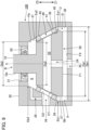
- Fig. 1 is a cross-sectional view illustrating a configuration of a valve device 100 according to a first embodiment of the present invention.
- the valve device 100 is a switching valve for controlling a flow path of a liquid.
- the valve device 100 is a multi-control valve that is mounted to an automobile for controlling, for example, a coolant used in the automobile (e.g., cooling water).
- the valve device 100 includes a valve member B, a housing 30, a first seal 40, a second seal 50, and a spring 61.
- the valve member B is a rotary valve that switches a flow path of the coolant by rotating about a rotation axis C.
- the housing 30 is a structure for accommodating and supporting the valve member B.
- the first seal 40 and the second seal 50 are each an elastic body disposed between the valve member B and the housing 30.
- first direction Z1 a direction opposite to the first direction Z1
- second direction Z2 a direction opposite to the first direction Z1
- first direction Z1 is a vertically downward direction
- second direction Z2 is a vertically upward direction
- a direction of a circumference of a virtual circle of any diameter around the rotation axis C is referred to as a “circumferential direction” and a direction of a radius of the virtual circle is referred to as a "radial direction.”
- the valve member B includes a shaft portion 10 and a rotor 20.
- the shaft portion 10 and the rotor 20 are formed as a single unit from various resins, for example.
- the shaft portion 10 is a cylindrical portion rotatable about the rotation axis C.
- the rotation axis C corresponds to a central axis of the shaft portion 10.
- An end of the shaft portion 10 in the first direction Z1 is coupled to the rotor 20.
- Another end of the shaft portion 10 in the second direction Z2 is directly or indirectly coupled to a motor (not shown).
- the shaft portion 10 rotates about the rotation axis C in conjunction with operation of the motor.
- the shaft portion 10 may be configured separately from and fixed to the rotor 20.
- the rotor 20 is a rotatable body that rotates together with the shaft portion 10 about the rotation axis C.
- An outer surface U of the rotor 20 includes a first surface F1, a second surface F2, and an outer circumferential surface Qb.
- the first surface F1 and the second surface F2 are each flat circular surfaces that are perpendicular to the rotation axis C.
- the first surface F1 is a lower surface facing in the first direction Z1
- the second surface F2 is an upper surface facing in the second direction Z2.
- the shaft portion 10 protrudes from a center of the second surface F2 in the second direction Z2.
- the outer circumferential surface Qb of the rotor 20 includes a cylindrical surface 21 and a conical surface 22.
- the conical surface 22 is located in the first direction Z1 relative to the cylindrical surface 21, and is contiguous with the first surface F1.
- the cylindrical surface 21 is located in the second direction Z2 relative to the conical surface 22, and is contiguous with the second surface F2.
- the conical surface 22 is a tapered rotatable surface a diameter of which increases in the second direction Z2. That is, an outer diameter Da1 at an end Ea1 of the conical surface 22 in the first direction Z1 is less than an outer diameter Da2 at an end Ea2 of the conical surface 22 in the second direction Z2 (Da1 ⁇ Da2).
- the rotor 20 includes a first flow path 23 and a vertical flow path 24.
- the first flow path 23 extends in a direction perpendicular (e.g., radially) to the rotation axis C.
- the first flow path 23 has circular first openings O1 on the outer circumferential surface Qb of the rotor 20. Specifically, the first openings O1 are circumferentially spaced apart from each other on the conical surface 22. For convenience of description, in the following explanation reference is made to one of the first openings O1.
- the vertical flow path 24 extends from the first flow path 23 in the first direction Z1. Specifically, the vertical flow path 24 extends through the rotor 20 from the inner wall surface of the first flow path 23 to the first surface F1.
- the vertical flow path 24 extends along the rotation axis C.
- the rotor 20 also includes a communication path 25.
- the communication path 25 is a flow path that extends along the rotation axis C.
- the communication path 25 extends through the rotor 20 from the inner wall surface of the first flow path 23 to the second surface F2. That is, the first flow path 23 inside the rotor 20 and a space outside the rotor 20 are communicable via the communication path 25.
- the housing 30 includes an accommodating portion R, which is a space for accommodating the valve member B.
- the inner surface H of the accommodating portion R in the housing 30 includes a cylindrical surface 31, a third surface F3, an inner circumferential surface Ha, and a fourth surface F4.
- the cylindrical surface 31 is a rotatable surface spaced apart from and facing the outer circumferential surface Qa of the shaft portion 10.
- the third surface F3 is a flat annular surface perpendicular to the rotation axis C, and is spaced apart from and faces the second surface F2 of the rotor 20.
- a spring 61 is an elastic member for biasing the valve member B (rotor 20) in the first direction Z1.
- the spring 61 is disposed between the second surface F2 and the third surface F3.
- the spring 61 is a coil spring that surrounds the shaft portion 10.
- the inner circumferential surface Ha includes a cylindrical surface 32 and a conical surface 33.
- the third surface F3 connects the cylindrical surface 31 with the cylindrical surface 32.
- the cylindrical surface 32 is a rotatable surface and is spaced apart from and faces the outer circumferential surface Q (Qa,Qb) of the valve member B.
- the cylindrical surface 32 connects the third surface F3 with the conical surface 33.
- the conical surface 33 is a tapered rotatable surface that increases in diameter in the second direction Z2. That is, an outer diameter Db1 at an end Eb1 of the conical surface 33 in the first direction Z1 is less than an outer diameter Db2 at an end Eb2 of the conical surface 22 in the second direction Z2 (Db1 ⁇ Db2).
- the conical surface 33 is spaced apart from and faces the conical surface 22 of the rotor 20. That is, relative to the rotation axis C, an angle of the conical surface 22 and an angle of the conical surface 33 are equivalent.
- the conical surface 33 connects the cylindrical surface 32 with the fourth surface F4.
- the fourth surface F4 is a flat circular surface perpendicular to the rotation axis C, and is spaced apart from and faces the first surface F1 of the rotor 20. That is, the fourth surface F4 is a bottom surface that faces in the second direction Z2 within the accommodating portion R.
- the housing 30 includes a second flow path 34 and a third flow path 35.
- the second flow path 34 extends in a direction perpendicular to the rotation axis C (i.e., radially).
- the second flow path 34 has circular second openings O2 on the inner circumferential surface Ha of the accommodating portion R. Specifically, the second openings O2 are circumferentially spaced apart from each other on the conical surface 33 of the accommodating portion R. In the following description, for convenience of explanation, reference is made to one of the second openings O2.
- the third flow path 35 extends from the accommodating portion R in the first direction Z1.
- valve member B When the valve member B is at a predetermined angle of rotation around the rotation axis C (hereinafter, a "communication state"), one of the first openings O1 and one of the second openings O2 overlap each other in the radial direction. Specifically, in the communication state, the first flow path 23 and the second flow path 34 are in linear communication. That is, the first opening O1 and the second opening O2 are communicable with each other.
- the first seal 40 is an elastic body disposed between an outer surface U of the rotor 20 and an inner surface H of the accommodating portion R. Specifically, the first seal 40 is disposed between the outer circumferential surface Qb of the rotor 20 and the inner circumferential surface Ha of the accommodating portion R. The first seal 40 elastically supports the rotor 20 while sealing the clearance between the outer circumferential surface Qb and the inner circumferential surface Ha.
- Various rubber materials such as chloroprene rubber (CR) or polyurethane rubber (PUR), are examples of materials that can be used for the first seal 40.
- Fig. 2 is a side view of the first seal 40.
- the first seal 40 includes a first portion 41, a second portion 42, and a plurality of connecting parts 43.
- the first portion 41 and the second portion 42 are annular.
- An outer diameter of the first portion 41 is less than an outer diameter of the second portion 42.
- the plurality of connecting parts 43 interconnects the first portion 41 and the second portion 42.
- the connecting parts 43 are spaced apart from each other along the circumferential direction of the first portion 41 and the second portion 42.
- an inner circumferential surface of the first seal 40 has a projection 45.
- a projection 45 extends in the circumferential direction from the inner circumferential surface of each of the first portion 41 and the second portion 42.
- the inner circumferential surface of the first seal 40 may be coated with a low-friction material such as a PTFE (polytetrafluoroethylene), or the first seal 40 may be formed in its entirety from a low-friction material such as PTFE.
- the first seal 40 is disposed in the groove 36 of the conical surface 33. That is, an outer circumferential surface of the first seal 40 is in contact with the conical surface 33 of the housing 30.
- the inner circumferential surface of the first seal 40 is in contact with the conical surface 22 of the rotor 20.
- the projection 45 of the inner circumferential surface of the first seal 40 is in contact with the conical surface 22.
- the first seal 40 is disposed between the conical surface 22 of the rotor 20 and the conical surface 33 of the housing 30.
- the valve member B is biased in the first direction Z1 by the spring 61, thereby causing the rotor 20 to be pressed against the first seal 40.
- sufficient surface pressure (contact pressure) between the first seal 40 and the rotor 20 can be maintained.
- properties of the spring 61 such as its elastic modulus are set so that the surface pressure between the outer circumferential surface Qb of the rotor 20 and the first seal 40 exceeds a coolant pressure in the accommodating portion R.
- the first seal 40 is fixed to the housing 30.
- the rotor 20 rotates with the outer circumferential surface Qb (conical surface 22) in contact with the inner circumferential surface of the first seal 40. That is, the outer circumferential surface Qb of the rotor 20 slides against the inner circumferential surface of the first seal 40.
- the first portion 41 of the first seal 40 is located further in the first direction Z1 relative to the first opening O1 and the second opening O2. That is, on the rotation axis C the position of the first portion 41 is further in the first direction Z1 relative to the positions of the first opening O1 and the second opening O2.
- the second portion 42 is located further in the second direction Z2 relative to the first opening O1 and the second opening O2. That is, on the rotation axis C, the position of the second portion 42 is further in the second direction Z2 relative to the positions of the first opening O1 and the second opening O2.
- the second seal 50 is disposed between the outer circumferential surface Qa of the shaft portion 10 and the inner circumferential surface Ha of the accommodating portion R (i.e., the cylindrical surface 31), to seal a clearance between the outer circumferential surface Qa and the inner circumferential surface Ha.
- the second seal 50 is located further in the second direction Z2 relative to the second portion 42 of the first seal 40. That is, on the rotation axis C, the position of the second seal 50 is further in the second direction Z2 relative to the position of the second portion 42.
- the second portion 42 is located between the first portion 41 and the second seal 50.
- coolant is supplied from the second flow path 34 to the first flow path 23 via one of the plurality of second openings O2 that is brought into communication with a first opening O1 dependent on a rotational angle of the valve member B, and the coolant is discharged from the first flow path 23 to the outside via the vertical flow path 24 and the third flow path 35.
- coolant supplied from the third flow path 35 to the first flow path 23 via the vertical flow path 24 is discharged from the first flow path 23 to the second flow path 34 via one of the plurality of second openings O2 that is brought into communication with a first opening O1 dependent on the rotational angle of the valve member B.
- the coolant is controlled dependent on the angle of the valve member B.
- the outer surface U (F1,F2,Qb) of the rotor 20 and the inner surface H of the housing 30 are not in direct contact with each other. Therefore, with the rotor 20 pressed against the first seal 40 by the spring 61, the first surface F1 of the rotor 20 is not in contact with the fourth surface F4 of the accommodating portion R. That is, the force exerted on the rotor 20 by the spring 61 does not directly act on the housing 30 from the rotor 20, and is received by the first seal 40.
- a clearance between the conical surface 22 of the rotor 20 and the conical surface 33 of the housing 30 depends on dimensional errors in the valve member B or in the housing 30. For example, if the dimension of the rotor 20 along the rotation axis C is less than a design value, the sealing clearance will exceed the design value. Moreover, if the dimension of the rotor 20 along the rotation axis C exceeds the design value, the sealing clearance will be less than the design value.
- the surface pressure (contact pressure) acting on the first seal 40 from the conical surface 22 of the rotor 20 and the conical surface 33 of the housing 30 is affected by dimensional errors in the valve member B or in the housing 30.
- the surface pressure will be excessive if the sealing clearance is at a minimum dimension within the tolerance.
- the surface pressure will be insufficient if the sealing clearance is at a maximum dimension.
- the first seal 40 includes the first portion 41 and the second portion 42 at different positions along the rotation axis C. Therefore, compared with a configuration in which the first seal 40 is constituted of only one of the first portion 41 or the second portion 42, it is possible to stably maintain an attitude of the rotor 20.
- the space S shown in Fig. 1 is surrounded by the outer circumferential surface Q (Qa,Qb) of the valve member B, the inner surface H of the accommodating portion R, the second portion 42 of the first seal 40, and the second seal 50. That is, of a space between the outer circumferential surface Q and the inner surface H, the space S comprises a space between the second portion 42 and the second seal 50.
- the communication path 25 described above is a flow path that communicates the space S with the first flow path 23. That is, the space S is communicable with the first flow path 23 via the communication path 25.
- the space S is an example of a "first space.”
- Fig. 3 shows a configuration in which the communication path 25 is not included (hereinafter, "Comparative Example 2").
- the space S is a sealed space.
- slight leakage of the coolant through the first seal 40 may be acceptable.
- coolant that does leak through the first seal 40 is eventually recirculated by flowing into another flow path upon switching of flow paths by the switching valve, slight leakage of the coolant is not particularly problematic. Nonetheless, given these circumstances, as indicated by the dashed arrow in Fig.
- the coolant flowing through the first flow path 23 and the second flow path 34 may leak from between the second portion 42 of the first seal 40 and the outer circumferential surface Qb of the rotor 20 into the space S. Since the space S is sealed, when the coolant enters the space S pressure in the space S increases. That is, pressure builds up in the space S. As the pressure builds up, excessive force acts on the first seal 40 or the second seal 50, and as a result, problems such as deformation of the seals may occur. Further, the pressure buildup in the space S may cause the rotor 20 to be pressed, and as a result, the first seal 40 may be pressed excessively downward by the rotor 20. As a result, a sliding resistance between the rotor 20 and the first seal 40 may increase.
- the space S and the first flow path 23 are in communication with each other via the communication path 25. Therefore, an increase in pressure caused by leakage of the coolant into the space S does not occur.
- the communication path 25 extends from the second surface F2 of the rotor 20 to the first flow path 23 along the rotation axis C.
- the surface of the rotor 20 of the valve member B includes a first region on which a coolant pressure acts in the first direction Z1 from the accommodating portion R, and a second region on which a coolant pressure acts in the second direction Z2.
- a first area S1 of the first region is larger than a second area S2 of the second region (S1 > S2).
- the first region includes, for example, the second surface F2.
- the first region includes, in addition to a plane perpendicular to the rotation axis C (e.g., the second surface F2), an inclined surface on which a coolant pressure component in the first direction Z1 acts.
- the second region includes, for example, the first surface F1.
- the second region includes an inclined surface on which a coolant pressure component in the second direction Z2 acts.
- a size of the spring 61 for biasing the valve member B in the first direction Z1 can be reduced, as compared with a configuration in which the first area S1 and the second area S2 are substantially the same.
- the spring 61 may be omitted in a case in which a sufficient level of bias in the first direction Z1 on the valve member B can be achieved by the difference in area between the first area S1 and the second area S2.
- the spring 61 for biasing the valve member B in the first direction Z1 is not required or the size thereof is reduced, and therefore it is possible to reduce a size of the valve device 100.
- reduction in size of the valve device is not limited by an element used to bias the valve member B (e.g., spring 61).
- the first seal 40 is in contact with the conical surface 22 of the rotor 20.
- the difference between the first area S1 and the second area S2 causes the valve member B to be biased in the first direction Z1, and, as a result, the rotor 20 is pressed against the first seal 40. Therefore, it is easy to secure the surface pressure between the outer circumferential surface Qb of the rotor 20 and the first seal 40. Consequently, according to the first embodiment, the sealing performance of the coolant by the first seal 40 can be maintained at a high level.
- Fig. 4 is a cross-sectional view illustrating the configuration of the valve device 100 in the second embodiment.
- the valve device 100 according to the second embodiment, as in the first embodiment, is mounted to an automobile as a multi-control valve for controlling the coolant used in an automobile (e.g., cooling water).
- the valve device 100 includes a valve member B, a housing 30, a first seal 40, and a second seal 50.
- the configuration of the rotor 20 in the valve member B is different from that of the first embodiment.
- the rotor 20 of the second embodiment is a rotatable body having an outer surface U.
- the outer surface U includes a first surface F1, a second surface F2, and an outer circumferential surface Qb.
- the first surface F1 is a lower surface facing in the first direction Z1
- the second surface F2 is an upper surface facing in the second direction Z2.
- a shaft portion 10 protrudes from the center of the second surface F2 in the second direction Z2.
- the outer circumferential surface Qb of the rotor 20 includes a conical surface 26 and a cylindrical surface 27.
- the conical surface 26 is located in the second direction Z2 relative to the cylindrical surface 27, and is contiguous with the second surface F2.
- the conical surface 26 is a tapered rotatable surface that increases in diameter in the first direction Z1. That is, the outer diameter Da1 at the end Ea1 of the first direction Z1 of the conical surface 26 is larger than the outer diameter Da2 at the end Ea2 of the second direction Z2 of the conical surface 26 (Da1 > Da2).
- the cylindrical surface 27 is located in the first direction Z1 relative to the conical surface 26, and is contiguous with the first surface F1.
- the rotor 20 of the second embodiment includes a first flow path 23 and a vertical flow path 24.
- the first flow path 23 has a first opening O1 on the outer circumferential surface Qb of the rotor 20.
- the vertical flow path 24 extends from the first flow path 23 in the first direction Z1. Specifically, the vertical flow path 24 extends along the rotation axis C through the rotor 20 from the inner wall surface of the first flow path 23 to the first surface F1.
- An accommodating portion R of the housing 30 in the second embodiment has an inner surface H.
- the inner surface H includes a cylindrical surface 31, a third surface F3, an inner circumferential surface Ha, and a fourth surface F4.
- the cylindrical surface 31 and the third surface F3 are substantially the same as those of the first embodiment.
- the inner circumferential surface Ha includes a conical surface 37 and a cylindrical surface 38.
- the third surface F3 connects the cylindrical surface 31 with the conical surface 37.
- the conical surface 37 is a tapered rotatable surface that increases in diameter in the first direction Z1. That is, the outer diameter Db1 at the end Eb1 of the conical surface 37 in the first direction Z1 is greater than the outer diameter Db2 at the end Eb2 of the conical surface 37 in the second direction Z2 (Db1 > Db2).
- the conical surface 37 faces and is spaced apart from the conical surface 26 of the rotor 20. That is, relative to the rotation axis C, an angle of the conical surface 26 and an angle of the conical surface 37 are equivalent.
- the conical surface 37 connects the third surface F3 with the cylindrical surface 38.
- the cylindrical surface 38 is a rotatable surface that faces and is spaced apart from the outer circumferential surface Qb of the rotor 20.
- the cylindrical surface 38 connects the conical surface 37 with the fourth surface F4.
- the fourth surface F4 is a flat circular surface that is perpendicular to the rotation axis C, and is spaced apart from and faces the first surface F1 of the rotor 20.
- the housing 30 includes a second flow path 34 and a third flow path 35.
- the second flow path 34 has a second opening O2 on the inner circumferential surface Ha of the accommodating portion R.
- the second opening O2 is on the conical surface 37 of the accommodating portion R.
- the first seal 40 is an elastic body disposed between the outer circumferential surface Qb of the rotor 20 and the inner circumferential surface Ha of the accommodating portion R.
- Fig. 5 is a side view of the first seal 40.
- the first seal 40 includes a first portion 41, a second portion 42, and a plurality of connecting parts 43, similarly to the first embodiment.
- on the inner circumferential surface of the first seal 40 there is a projection 45.
- the outer diameter of the first portion 41 is less than the outer diameter of the second portion 42
- the outer diameter of the first portion 41 is more than the outer diameter of the second portion 42.
- the first seal 40 is disposed in a groove 36 in the conical surface 37 of the housing 30. That is, the outer circumferential surface of the first seal 40 is in contact with the conical surface 37 of the housing 30. On the other hand, the inner circumferential surface of the first seal 40 is in contact with the conical surface 26 of the rotor 20. More specifically, the projection 45 on the inner circumferential surface of the first seal 40 is in contact with the conical surface 26. As in the first embodiment, the first seal 40 is fixed to the housing 30, and the outer circumferential surface Qb of the rotor 20 slides relative to the inner circumferential surface of the first seal 40.
- the second seal 50 is disposed between the outer circumferential surface Qa of the shaft portion 10 and the inner circumferential surface Ha of the accommodating portion R (i.e., the cylindrical surface 31), and the second seal 50 seals the clearance between the outer circumferential surface Qa and the inner circumferential surface Ha.
- the second seal 50 is in the second direction Z2 relative to the second portion 42 of the first seal 40. That is, the second portion 42 is located between the first portion 41 and the second seal 50 in a side view along the radial direction.
- the rotor 20 includes a communication path 25.
- the communication path 25 is a flow path extending along the rotation axis C through the rotor 20 from the inner wall surface of the first flow path 23 to the second surface F2. That is, the first flow path 23 and a space S outside the rotor 20 communicate with each other via the communication path 25.
- the space S comprises a space between the second portion 42 of the first seal 40 and the second seal 50.
- the surface of the rotor 20 of the valve member B includes a first region on which a coolant pressure acts in the first direction Z1 from the accommodating portion R, and a second region on which a coolant pressure acts in the second direction Z2.
- a first area S1 of the first region is smaller than a second area S2 of the second region (S1 ⁇ S2). Therefore, assuming that a uniform pressure acts on the entire surface of the rotor 20, the coolant pressure acting in the first direction Z1 on the first region is less than the coolant pressure acting in the second direction Z2 on the second region.
- a force corresponding to a difference between the coolant pressure acting in the first direction Z1 and the coolant pressure acting in the second direction Z2 serves to bias the valve member B in the second direction Z2. Therefore, in the second embodiment, it is possible to eliminate an element, such as a spring, for biasing the valve member B in the second direction Z2.
- size reduction is not limited dependent on an element used to bias the valve member B.
- a spring for biasing the rotor 20 in the second direction Z2 may be disposed (see Fig. 7 ).
- the first seal 40 is in contact with the conical surface 26 of the rotor 20.
- the difference between the first area S1 and the second area S2 causes the valve member B to be biased in the second direction Z2, and, as a result, the rotor 20 is pressed against the first seal 40. Therefore, it is easy to secure the surface pressure between the outer circumferential surface Qb of the rotor 20 and the first seal 40. That is, according to the first embodiment, the sealing performance of the coolant by use of the first seal 40 can be maintained at a high level.
- Fig. 6 is a cross-sectional view illustrating a configuration of the valve device 100 according to a third embodiment.
- the valve device 100 according to the third embodiment is a configuration in which a spring 62 is added to the valve device 100 of the second embodiment.
- the spring 62 is an elastic member disposed between the second surface F2 and the third surface F3.
- the spring 62 is a coiled spring that is disposed to surround the shaft portion 10, and biases the valve member B in the first direction Z1.
- the valve member B since the first area S1 is smaller than the second area S2, the valve member B may be excessively biased in the second direction Z2, thus causing the rotor 20 to be excessively pressed against the first seal 40.
- the valve member B is biased in the first direction Z1 by the spring 62. That is, in a state in which the first area S1 is smaller than the second area S2, the spring 62 acts to counter in the first direction Z1 the biasing force acting in the second direction Z2. As a result, it is possible to reduce the likelihood of the rotor 20 being excessively pressed against the first seal 40.
- the surface pressure between the first seal 40 and the rotor 20 can be adjusted to be maintained within a moderate range.
- Fig. 7 is a cross-sectional view illustrating a configuration of the valve device 100 in the fourth embodiment.
- the valve device 100 of the fourth embodiment is a configuration in which a spring 63 is added to the valve device 100 of the second embodiment.
- the spring 63 is an elastic member for biasing the valve member B (rotor 20) in the second direction Z2.
- the spring 63 is disposed between the first surface F1 and the fourth surface F4.”
- the outer surface U (F1,F2,Qb) of the rotor 20 and the inner surface H of the housing 30 are not in direct contact with each other. Therefore, the rotor 20 is pressed against the first seal 40 by the spring 63 with the second surface F2 not in contact with the third surface F3. That is, the pressing force acting on the rotor 20 from the spring 63 does not directly act on the housing 30 from the rotor 20, and is received by the first seal 40. Accordingly, as in the first embodiment, it is possible to apply an appropriate surface pressure to the first seal 40 regardless of dimensional errors in the valve member B or in the housing 30.
- Fig. 8 is a cross-sectional view illustrating a configuration of a valve device 100 according to a fifth embodiment.
- the rotor 20 includes the communication path 25, which communicates the space S with the first flow path 23.
- the housing 30 includes a communication path 28 that acts in substantially the same manner as the communication path 25.
- the configuration is substantially the same as that of the first embodiment.
- the housing 30 of the fifth embodiment includes the communication path 28, which communicates the space S with the second flow path 34.
- the communication path 28 is a flow path from the inner surface H of the accommodating portion R (i.e., the cylindrical surface 32) to the inner wall surface of the second flow path 34.
- the space S and the second flow path 34 communicate with each other via the communication path 28. Therefore, no increase in pressure occurs due to leakage of the coolant into the space S.
- the fifth embodiment similarly to the first embodiment, it is possible to suppress or prevent pressure buildup in the space S, as compared with Comparative Example 2 of Fig. 3 .
- the configuration shown in Fig. 8 is based on that of the first embodiment, in which the rotor 20 increases in diameter in the second direction Z2.
- a configuration substantially the same as the fifth embodiment may be adopted.
- the housing 30 may include a communication path 28 that communicates the space S with the second flow path 34.
- the spring 62 of the third embodiment may be added to the configuration of Fig. 9 .
- Figs. 10 and 11 are cross-sectional views illustrating a configuration of the valve device 100 according to a sixth embodiment.
- the rotor 20 (valve member B) is movable in the direction of the rotation axis C (Z1 and Z2).
- the rotor 20 of the sixth embodiment is movable along the rotation axis C between the first position shown in Fig. 10 and the second position shown in Fig. 11 .
- the second position is in the second direction Z2 relative to the first position. In other words, the second position is above the first position.
- the first position corresponds to the lower end of the range in which the rotor 20 can move
- the second position corresponds to the upper end of the range.
- the housing 30 of the sixth embodiment includes a projection 71 in addition to elements substantially the same as those of the first embodiment.
- the projection 71 is a portion projecting from the fourth surface F4 in the second direction Z2.
- the projection 71 is formed integrally with the fourth surface F4.
- the projection 71 may be configured as a separate unit from the housing 30 and fixed to the fourth surface F4.
- a recess 72 is included in the first surface F1 (lower surface) of the rotor 20 in the sixth embodiment.
- the recess 72 has a shape and size that can accommodate the projection 71.
- the projection 71 is located within the recess 72 when viewed in the direction of the rotation axis C.
- the top surface of the projection 71 is not in contact with the bottom surface of the recess 72.
- the outer surface U of the rotor 20 is not in contact with the inner surface H of the housing 30.
- the inner surface H of the housing 30 includes a surface of the projection 71 (e.g., a top surface). Therefore, in the first state, the first surface F1 is not in contact with the fourth surface F or with the top surface of the projection 71.
- the spring 61 presses the rotor 20 against the first seal 40. That is, the force exerted on the rotor 20 by the spring 61 does not directly act on the housing 30 from the rotor 20, and is received by the first seal 40.
- the first surface F1 of the rotor 20 comes into contact with the top surface of the projection 71, as illustrated in Fig. 11 .
- the rotor 20 is biased in the first direction Z1 by the spring 61, but contact of first surface F1 with the top surface of the projection 71 prevents the rotor 20 from moving in the first direction Z1.
- the position of the rotor 20, in which the outer surface U of the rotor 20 (the first surface F1) is in contact with the inner surface H of the housing 30 (the top surface of the projection 71), is the second position, as described above. That is, when the rotor 20 is in the second position (hereinafter, "second state"), the first surface F1 of the rotor 20 is in contact with the top surface of the projection 71.
- the second state a clearance between the conical surface 22 of the rotor 20 and the conical surface 33 of the housing 30 (sealing clearance) increases compared with the first state. Due to the increase in the sealing clearance, the conical surface 22 is spaced from the first seal 40. Thus, the surface pressure acting on the first seal 40 from the rotor 20 and housing 30 is less than the surface pressure in the first state. Consequently, the sliding resistance of the rotor 20 is reduced as compared with that in the first state. Therefore, in the second state, a torque required to rotate the rotor 20 is reduced compared with the first state.
- the second position corresponds to a temporary or transient position for switching the flow path by rotation of the rotor 20. It is of note that in the second state, the conical surface 22 of the rotor 20 may be maintained in contact with the first seal 40.
- the first surface F1 and the fourth surface F4 it is not necessary for the first surface F1 and the fourth surface F4 to be in constant contact with each other. Specifically, the first surface F1 and the fourth surface F4 need not be in contact with each other when a surface pressure acting on the first seal 40 from the rotor 20 is maintained within a predetermined range (i.e., when sealed); while in other states the first surface F1 and the fourth surface F4 may be in contact with each other.
- the surface of the rotor 20 includes the first region, on which coolant pressure in the first direction Z1 acts, and the second region, on which coolant pressure in the second direction Z2 acts, the first area S1 of the first region being larger than the second area S2 of the second region (S1 > S2). Therefore, the coolant pressure acting on the first region in the first direction Z1 exceeds the coolant pressure acting on the second region in the second direction Z2.
- a pressure difference between the first flow path 23 and the space S by way of the pressure adjusting valve 80, a relationship between the coolant pressure acting on the first region and the coolant pressure acting on the second region can be adjusted. Therefore, a biasing force acting on the valve member B due to the difference in area between the first area S1 and the second area S2 can be adjusted by way of the pressure adjusting valve 80.
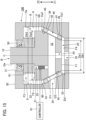
- a controller 81 as shown in Fig. 15 may dynamically control characteristics of the pressure adjusting valve 80 (e.g., the pressure difference between the first flow path 23 and the space S).
- the controller 81 dynamically controls the pressure adjusting valve 80 depending on the pressure of the first flow path 23 or space S.
- the pressure difference between the first flow path 23 and the space S can be adjusted by the pressure adjusting valve 80 such that a target biasing force acts on the valve member B dependent on the difference between the first area S1 and the second area S2.
- the pressure of the first flow path 23 or the space S is measured for example by a pressure sensor disposed in the accommodating portion R.
- Fig. 15 shows an embodiment in which the pressure adjusting valve 80 is added to the configuration of the first embodiment.
- substantially the same configuration is adopted in the second to the sixth embodiments.
- the pressure adjusting valve 80 is disposed in the communication path 28 formed in the housing 30. The pressure adjusting valve 80 adjusts the pressure difference between the second flow path 34 and the space S.
- FIG. 16 illustrates a configuration in which a movable portion 30a is disposed in the housing 30.
- the movable portion 30a is a cylindrical member with a threaded groove on the outer circumferential surface, and is inserted into the cylindrical surface 31 of the housing 30.
- the second seal 50 is disposed between the inner circumferential surface of the movable portion 30a and the outer circumferential surface Qa of the shaft portion 10.
- the cylindrical surface 31 of the housing 30 has a threaded groove that meshes with the threaded groove of the outer circumferential surface of the movable portion 30a.
- the spring 61 is disposed between the lower surface of the movable portion 30a and the second surface F2 of the rotor 20. Accordingly, the length of the spring 61 is changed by moving the movable portion 30a along the rotation axis C. That is, by moving the movable portion 30a, the biasing force acting on the rotor 20 from the spring 61 can be adjusted.
- the controller 82 shown in Fig. 16 may move the movable portion 30a toward the rotation axis C.
- the controller 82 moves the movable portion 30a depending on a state of the valve device 100.
- the state of the valve device 100 is, for example, a surface pressure acting on the first seal 40 from the rotor 20 or the housing 30, a pressure in the accommodating portion R, or a biasing force acting on the rotor 20 from the spring 61.
- the state of the valve device 100 is measured, for example, by various sensors disposed in the accommodating portion R.
- a configuration for adjusting the biasing force acting on the rotor 20 by the spring 61 may be freely selected, and is not limited thereto.
- the biasing force of the spring 61 is adjustable, and any spring (62,63,64) described as examples in the embodiments is also adjustable by use of substantially the same configuration.
- a coil spring is given as an example of the spring 61.
- a type of the spring 61 may be freely selected and is not limited thereto.
- An elastic member of any form, such as a leaf spring, can be employed as the spring 61.
- the biasing member for biasing the rotor 20 is not limited to the spring 61.
- Other types of elastic members, e.g., rubber materials, may be utilized in place of the spring 61 (or together with the spring 61) to bias the rotor 20.
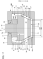
- the first area S1 and the second area S2 need not be larger than one another. Therefore, as illustrated in Fig. 18 , a cylindrical rotor 20 in which the outer circumferential surface Qb is a simple cylindrical surface may be employed.
- the inner circumferential surface Ha of the housing 30 is also constituted of a cylindrical surface, and the diameter of the first portion 41 and of the second portion 42 of the first seal 40 is the same.
- the communication path 25 communicates the space S with the first flow path 23, it is possible to attain the effect of suppressing or preventing a pressure buildup in the space S as compared with Comparative Example 2 in Fig. 3 , similarly to the first embodiment.
- a configuration that prevents the outer surface U of the rotor 20 and the inner surface H of the housing 30 from contacting each other is not limited to the embodiments as described above.
- a fourth seal 90 may be disposed between the first surface F1 of the rotor 20 and the fourth surface F4 of the housing 30.
- the rotor 20 is pressed against the fourth seal 90 by the spring 61 when the first surface F1 is not in touch with the fourth surface F4. That is, the pressing force acting on the rotor 20 by the spring 61 is received by the first seal 40. Accordingly, similarly to the first embodiment, it is possible to apply to the fourth seal 90 an appropriate surface pressure regardless of dimensional errors in the valve member B or in the housing 30.
- n-th (where n is a natural number) in the present application is used only as a formal and convenient label for distinguishing notated elements, and has no substantial meaning. Accordingly, there is no limitation inferable from the notation "n-th” with respect to the position of each element or order of manufacture.
- valve device 10...shaft portion, 20...rotor, 21,31,32,38...cylindrical surface, 22,26,37...conical surface, 23...first flow path, 24...vertical flow path, 25,28...communication path, 27... cylindrical surface, 30...housing, 33...conical surface, 34...second flow path, 35...third flow path, 36...groove, 39...third seal, 40...first seal, 41...first portion, 42...second portion, 43... connecting part, 50...second seal, 61,62,63,64...spring, 71...projection, 72...recess, 81,82...controller.
Landscapes
- Engineering & Computer Science (AREA)
- General Engineering & Computer Science (AREA)
- Mechanical Engineering (AREA)
- Taps Or Cocks (AREA)
- Multiple-Way Valves (AREA)
Applications Claiming Priority (2)
| Application Number | Priority Date | Filing Date | Title |
|---|---|---|---|
| JP2022043994 | 2022-03-18 | ||
| PCT/JP2023/008818 WO2023176633A1 (ja) | 2022-03-18 | 2023-03-08 | 弁装置 |
Publications (2)
| Publication Number | Publication Date |
|---|---|
| EP4495461A1 true EP4495461A1 (de) | 2025-01-22 |
| EP4495461A4 EP4495461A4 (de) | 2026-03-11 |
Family
ID=88023224
Family Applications (1)
| Application Number | Title | Priority Date | Filing Date |
|---|---|---|---|
| EP23770589.2A Pending EP4495461A4 (de) | 2022-03-18 | 2023-03-08 | Ventilvorrichtung |
Country Status (5)
| Country | Link |
|---|---|
| US (1) | US20260022784A1 (de) |
| EP (1) | EP4495461A4 (de) |
| JP (1) | JP7413615B1 (de) |
| CN (1) | CN118805047A (de) |
| WO (1) | WO2023176633A1 (de) |
Family Cites Families (7)
| Publication number | Priority date | Publication date | Assignee | Title |
|---|---|---|---|---|
| US2285222A (en) * | 1940-10-31 | 1942-06-02 | Mueller Co | Valve |
| GB850297A (en) * | 1957-09-24 | 1960-10-05 | Lewis Mervyn Cecil Seamark | Improvements in plug valves |
| US3930635A (en) * | 1974-07-26 | 1976-01-06 | Xomox Corporation | Leak-proof rotary, plug-type fluid control valve |
| US5727771A (en) * | 1996-07-29 | 1998-03-17 | Chang-Hong; Ahn | Fluid opening and closing valve |
| JP2013092176A (ja) * | 2011-10-24 | 2013-05-16 | Idea Link:Kk | 切替弁 |
| JP2015148288A (ja) * | 2014-02-07 | 2015-08-20 | カルソニックカンセイ株式会社 | 弁装置 |
| JP6810929B2 (ja) * | 2016-06-16 | 2021-01-13 | 株式会社不二工機 | 流路切換弁 |
-
2023
- 2023-03-08 CN CN202380024666.8A patent/CN118805047A/zh active Pending
- 2023-03-08 JP JP2023554053A patent/JP7413615B1/ja active Active
- 2023-03-08 EP EP23770589.2A patent/EP4495461A4/de active Pending
- 2023-03-08 WO PCT/JP2023/008818 patent/WO2023176633A1/ja not_active Ceased
- 2023-03-08 US US18/843,913 patent/US20260022784A1/en active Pending
Also Published As
| Publication number | Publication date |
|---|---|
| JPWO2023176633A1 (de) | 2023-09-21 |
| JP7413615B1 (ja) | 2024-01-15 |
| US20260022784A1 (en) | 2026-01-22 |
| WO2023176633A1 (ja) | 2023-09-21 |
| EP4495461A4 (de) | 2026-03-11 |
| CN118805047A (zh) | 2024-10-18 |
Similar Documents
| Publication | Publication Date | Title |
|---|---|---|
| US11846455B2 (en) | Valve needle assembly and electronic expansion valve having the valve needle assembly | |
| KR100317074B1 (ko) | 압력조정기 | |
| CN114144608B (zh) | 包括流体驱动密封的流体阀组件 | |
| CN114174704B (zh) | 包括具有密封件保持特征的阀主体的流体阀组件 | |
| JP5404645B2 (ja) | バルブ | |
| WO2011039918A1 (ja) | ロータリー弁 | |
| US9115812B2 (en) | Plug valve with a spring biased plug | |
| CN101203705A (zh) | 控制阀 | |
| CN107407429A (zh) | 阀装置 | |
| EP3524861A1 (de) | Dichtungsvorrichtung und dichtungsanordnung | |
| CN114207330A (zh) | 包括具有保持特征的密封件的流体阀组件 | |
| WO2013099823A1 (ja) | 流路切替バルブ | |
| CN111664266B (zh) | 阀装置 | |
| WO2020002337A1 (en) | Control valve | |
| EP4495461A1 (de) | Ventilvorrichtung | |
| EP4495463A1 (de) | Ventilvorrichtung | |
| EP4495464A1 (de) | Ventilvorrichtung | |
| CN115013575B (zh) | 压力调整阀 | |
| JP6768193B2 (ja) | 流量調整バルブ | |
| US11274750B2 (en) | Double eccentric valve | |
| US12305766B2 (en) | Three-way valve for flow rate control and temperature control device | |
| US11278929B2 (en) | Device for dispensing a flowable medium | |
| CN116981873A (zh) | 阀装置 | |
| JP6387753B2 (ja) | バルブ装置 | |
| CN118575027A (zh) | 用于旋转轴设备的柔性密封膜和密封组件 |
Legal Events
| Date | Code | Title | Description |
|---|---|---|---|
| STAA | Information on the status of an ep patent application or granted ep patent |
Free format text: STATUS: THE INTERNATIONAL PUBLICATION HAS BEEN MADE |
|
| PUAI | Public reference made under article 153(3) epc to a published international application that has entered the european phase |
Free format text: ORIGINAL CODE: 0009012 |
|
| STAA | Information on the status of an ep patent application or granted ep patent |
Free format text: STATUS: REQUEST FOR EXAMINATION WAS MADE |
|
| 17P | Request for examination filed |
Effective date: 20240912 |
|
| AK | Designated contracting states |
Kind code of ref document: A1 Designated state(s): AL AT BE BG CH CY CZ DE DK EE ES FI FR GB GR HR HU IE IS IT LI LT LU LV MC ME MK MT NL NO PL PT RO RS SE SI SK SM TR |
|
| DAV | Request for validation of the european patent (deleted) | ||
| DAX | Request for extension of the european patent (deleted) | ||
| A4 | Supplementary search report drawn up and despatched |
Effective date: 20260210 |
|
| RIC1 | Information provided on ipc code assigned before grant |
Ipc: F16K 5/02 20060101AFI20260204BHEP Ipc: F16K 5/16 20060101ALI20260204BHEP Ipc: F16K 5/18 20060101ALI20260204BHEP Ipc: F16K 11/085 20060101ALI20260204BHEP Ipc: F16K 11/083 20060101ALI20260204BHEP Ipc: F16K 39/06 20060101ALI20260204BHEP Ipc: F16K 5/04 20060101ALI20260204BHEP |