EP4495451A1 - Verbesserte reibungsmaterialien - Google Patents
Verbesserte reibungsmaterialien Download PDFInfo
- Publication number
- EP4495451A1 EP4495451A1 EP23306228.0A EP23306228A EP4495451A1 EP 4495451 A1 EP4495451 A1 EP 4495451A1 EP 23306228 A EP23306228 A EP 23306228A EP 4495451 A1 EP4495451 A1 EP 4495451A1
- Authority
- EP
- European Patent Office
- Prior art keywords
- graphite
- friction material
- material composition
- friction
- less
- Prior art date
- Legal status (The legal status is an assumption and is not a legal conclusion. Google has not performed a legal analysis and makes no representation as to the accuracy of the status listed.)
- Pending
Links
Images



Classifications
-
- F—MECHANICAL ENGINEERING; LIGHTING; HEATING; WEAPONS; BLASTING
- F16—ENGINEERING ELEMENTS AND UNITS; GENERAL MEASURES FOR PRODUCING AND MAINTAINING EFFECTIVE FUNCTIONING OF MACHINES OR INSTALLATIONS; THERMAL INSULATION IN GENERAL
- F16D—COUPLINGS FOR TRANSMITTING ROTATION; CLUTCHES; BRAKES
- F16D69/00—Friction linings; Attachment thereof; Selection of coacting friction substances or surfaces
- F16D69/02—Composition of linings ; Methods of manufacturing
- F16D69/025—Compositions based on an organic binder
- F16D69/026—Compositions based on an organic binder containing fibres
-
- C—CHEMISTRY; METALLURGY
- C01—INORGANIC CHEMISTRY
- C01B—NON-METALLIC ELEMENTS; COMPOUNDS THEREOF; METALLOIDS OR COMPOUNDS THEREOF NOT COVERED BY SUBCLASS C01C
- C01B32/00—Carbon; Compounds thereof
- C01B32/20—Graphite
- C01B32/21—After-treatment
-
- F—MECHANICAL ENGINEERING; LIGHTING; HEATING; WEAPONS; BLASTING
- F16—ENGINEERING ELEMENTS AND UNITS; GENERAL MEASURES FOR PRODUCING AND MAINTAINING EFFECTIVE FUNCTIONING OF MACHINES OR INSTALLATIONS; THERMAL INSULATION IN GENERAL
- F16D—COUPLINGS FOR TRANSMITTING ROTATION; CLUTCHES; BRAKES
- F16D2200/00—Materials; Production methods therefor
- F16D2200/006—Materials; Production methods therefor containing fibres or particles
- F16D2200/0069—Materials; Production methods therefor containing fibres or particles being characterised by their size
Definitions
- the present invention relates to friction material compositions comprising graphite materials.
- the invention further relates to methods of making such friction material compositions, as well as their uses.
- the invention relates to brake pads and brake pad assemblies comprising the friction material compositions of the present invention.
- Friction materials for brake pads, brake linings, clutch facings or the like used for the brake and the clutch of motorcars, railroad vehicles, industrial machines, etc. are generally made by combining and molding principal raw materials comprising at least one binder and at least one additive.
- Graphite powders have been previously employed in friction materials for brake pads.
- Typical graphite used in automotive brake pads comprises natural graphites and/or synthetic graphites of different particle sizes (from D90 of about 15 microns up to a D90 of about 2000 microns).
- EP 3 088 764 A1 discloses the use of resilient graphitic materials in non-asbestos organic (NAO) brake pads.
- a resilient graphitic carbon particle is made by expanding and forming a carbonaceous mesophase or coke, followed by graphitization at 1900 to 2700°C, in order to obtain a degree of graphitization of 80 to 95%, as measured according to X-ray analysis. It has improved volume recovery ratio when removing the added compressive load. In addition, crack formation is reduced, which in turn reduces chipping.
- EP 3 674 371 A1 relates to friction materials comprising graphite having a c/2 of 0.3358 nm or less and a spring-back of 40% or more.
- the brake pad market is evolving due to new regulations, which include regulations on dust emissions.
- coated brake discs may be used.
- the use of these types of brake discs requires new friction material compositions.
- brake pads for electric vehicles will need to have a more stable friction coefficient in order to reduce vibrations and noise.
- the present invention aims to provide friction material compositions having a highly stable friction coefficient.
- a stable friction coefficient is very important in order to have the same brake performance in all conditions, and it has a beneficial effect on noise reduction (less vibrations induced by unstable friction coefficient), which is a very important feature, in particular, for electric vehicles.
- the temperature of the brake pads and brake discs needs to be controlled during braking.
- a large increase in temperature can lead to a decrease in braking efficiency.
- the brake pad may deteriorate when overheated.
- the surface of the disc may change its crystalline structure and the cast-iron structure turns into a much harder phase, called cementite, which results is uneven braking.
- Intensification of extreme overheating leads to further propagation of the crystalline structure of cementite on the surface of the brake disc, causing a change in its geometry and the disc often requiring replacement.
- the present inventors have surprisingly found that by using specific graphite materials, it is possible to prepare friction materials having excellent properties.
- the friction material composition of the present invention may be used to prepare brake pads having improved friction coefficient stability. A stable friction coefficient is correlated with low squealing and vibrations, which would impair the quietness of the vehicle.
- inventive friction material compositions show a lower increase in temperature during braking. This is advantageous since overheating of the brake pad may cause a decrease in braking efficiency or the deteriorations of the material.
- the present invention provides a friction material composition comprising:
- the present invention provides a brake pad comprising the friction material composition of the present invention.
- the present invention provides a brake assembly comprising the brake pad of the present invention and a brake disc, wherein the brake disc is preferably a cast iron disc or a coated brake disc.
- the present invention provides a method of making the friction material composition of the present invention, comprising the steps of
- the present invention is directed to the use of the friction material composition of the present invention in the production of brake pads.
- the present invention is directed to the use of the friction material composition of the present invention for improving the friction coefficient stability of a brake pad comprising said friction material composition.
- the graphite material has a D90 to D10 ratio of less than 4.0, preferably less than 3.5, such as less than 3 or less than 2.5.
- the graphite material may have a D90 to D10 ratio of 1.1 to 4.5, preferably 1.1 to 4.0, 1.1 to 3.5, 1.2 to 3.5, 1.1 to 3.0, 1.2 to 3.0, 1.2 to 2.5 or 1.3 to 2.5.
- the graphite material may have a D90 to D10 ratio of 1.5 to 4.5, preferably 1.5 to 4.0, 1.5 to 3.5 or 1.5 to 3.0.
- the graphite material contained in the friction material composition of the present invention is further characterized by a Scott density of at least 0.5 g/cm 3 .
- the graphite material has a Scott density of at least 0.55 g/cm 3 , such as at least 0.6 g/cm 3 , at least 0.65 g/cm 3 or at least 0.70 g/cm 3 .
- the Scott density is 0.5 to 2.0 g/cm 3 , such as 0.55 to 2.0 g/cm 3 , 0.55 to 1.5 g/cm 3 , 0.6 to 1.5 g/cm 3 or 0.6 to 1 g/cm 3 , or 0.7 to 1 g/cm 3 .
- the Scott density can be measured using a Scott volumeter according to ASTM B 329-20.
- graphite material may be further defined by each D90 to D10 ratio and Scott density (of course provided they are not mutually exclusive).
- the graphite material of the present invention may have a D90 to D10 ratio of less than 4.0, and a Scott density of at least 0.6 g/cm 3 .
- the graphite material of the present invention has a D90 to D10 ratio of less than 3.5, and a Scott density of at least 0.6 g/cm 3 .
- the graphite material has a D90 to D10 ratio of 1.1 to 3.5 and a Scott density of 0.6 to 2.0 g/cm 3 .
- the graphite material is in some embodiments further characterized by a D90 of less than 60, or less than 55 ⁇ m, less than 50 ⁇ m, less than 45 ⁇ m, or less than 40 ⁇ m.
- the graphite material of the present invention is in some embodiments further characterized by a D90 of at least 5 ⁇ m or of at least 10 pm or of at least 15.0 ⁇ m.
- the graphite material may have a D90 of 5 to 60 pm, preferably of 10 to 50 pm, such as 15 to 40 pm (always provided that the ratio of D90 to D10 ratio is less than 4.5).
- the surface modification of the graphite material includes a surface modification by heat treatment, and in addition a surface coating obtained for example by a CVD process, coating the graphite material surface with amorphous carbon, or with a coating of a carbon precursor at the graphite material surface and carbonization by a subsequent heat treatment in an inert gas atmosphere.
- the graphite material used in the friction material composition of the present invention can be produced by the process described in detail below.
- the friction material composition of the present invention comprises at least one binder.
- Binders for use in friction material compositions are commonly known in the art. Examples of suitable binders are resins or cement binders.
- the friction material composition of the present invention further comprises at least one additive.
- the at least one additive may be selected from the group consisting of fibers, abrasives, lubricants, and/or fillers.
- the fibers are selected from one or more of aromatic polyamide fibers, poly(acrylonitrile) fibers, cellulose fibers, carbon fibers, steel fibers, brass fibers and copper fibers.
- the friction material composition comprises at least one abrasive, such as a hard abrasive or a mild abrasive.
- abrasive such as a hard abrasive or a mild abrasive.
- hard abrasives include zirconia, alumina, magnesium oxide, zirconium silicate, silica, silicon dioxide, sand, silicon carbide, mullite, and iron oxide.
- Hard abrasives tend to have higher values on the Mohs hardness scale.
- Other examples of abrasives include some grades of ceramic fibers including complex mineral silicates such as calcium magnesium silicate, calcium magnesium zirconium silicate, calcium magnesium aluminum silicate, and magnesium aluminum silicate, as well as andalusite, vermiculite, potassium titanate and chromite.
- abrasives that are mild in nature include iron oxides of different chemistries, other metallic oxides, and materials and minerals that have relatively lower values on the Mohs hardness scale.
- the hard abrasives are generally used in low concentrations while the mild abrasives are typically used in higher concentrations to achieve the same desired friction level.
- the abrasive may be selected from potassium titanate, iron oxide, magnesium oxide, andalusite, mullite, silicon carbide, vermiculite, zirconia, zirconium silicate, calcium compounds such as calcium fluoride, chromite and mixtures thereof.
- the graphite provided in step (a) is subjected to a milling step to obtain a milled graphite.
- the graphite may be milled by means of a vibrated mill, e.g. a NAEF mill with a wolfram Carbide Container.
- the milling includes mechanic spheroidization. In this process, flakes are mechanically turned into spherical shapes.
- a high speed rotational dry impact mill Hybridizer, type NHSe0, Nara Machinery Co.
- the milled graphite is fractionated in order to obtain a final milled graphite material that has a D90 to D10 ratio of less than 4.5 (step c).
- step c the milled graphite obtained in step (b) is removed.
- the size of the particles removed during fractionation depends on the PDS of the feed graphite used.
- the final milled graphite material provided in step (c) may further be subjected to a surface treatment (step (d)) to obtain a treated graphite material.
- the surface treatment may comprises a surface treatment by heat treatment and/or a surface coating treatment, such as a surface coating obtained by a chemical vapor deposition (CVD) treatment or an amorphous carbon coating treatment.
- CVD chemical vapor deposition
- a CVD treatment process may be performed using for example a rotary kiln, a fluidized bed furnace or a fixed bed furnace as is known from prior art applications WO 2016/008951 or EP 0 977 292 .
- a hydrocarbon gas such as propane, methane or toluene and benzene vapors are decomposed at temperatures between 600°C and 1200°C.
- the obtained final materials are coated with a 10 nm to 100 nm continuous layer of amorphous carbon and 0.5 to 30 wt% can have hydrophobic or hydrophilic nature.
- Any other known CVD processes for depositing pyrolytic carbon may also be employed, such as for example thermal CVD, Plasma Enhanced CVD, Hot-Filament CVD, Low Pressure CVD, Liquid Injection CVD, etc.
- the treated graphite material obtained at the end of step (d) or the final milled graphite material obtained at the end of step (c) is mixed with at least one binder and at least one additive (step (e)) to form a friction material composition.
- Other materials which may be used in friction material compositions may be added as well.
- the mixing may involve dry mixing the ingredients in a standard tumble mixer, with optional use of plows and choppers, to blend the ingredients into a homogeneous mixture.
- the provided feed graphite comprises a natural graphite
- the milling of step c) includes mechanic spheroidization
- step (d) includes a chemical vapor deposition (CVD) treatment.
- the friction material composition may be obtained in the form of a powder.
- the present invention provides for a brake pad comprising a friction material composition according to the present invention.
- the brake pad may comprise a backing plate and a friction pad fixed to the backing plate, wherein the friction pad is fabricated of the friction material composition of the present invention.
- the ratio of the maximum friction coefficient to the minimum friction coefficient of the brake pad is less than 2, wherein the friction coefficient is measured according to SAE J2522.
- the stability of the friction coefficient of the brake pad is improved compared to a brake pad otherwise identical but not comprising the graphite material as defined herein.
- the friction material composition of the present invention may be pressed on a backing plate to form a brake pad.
- the mixture is treated by compression molding, or hot compression molding or curing by heat treatment, or combinations of these.
- the friction material composition may be pressed in a heated mold.
- the mold may be heated to a temperature of 120 to 170°C, preferably 140 to 160°C, most preferably 150°C.
- the resulting brake pads are then heated up, followed by scorching.
- the heating may be performed up to a temperature of 225°C and the scorching at 600°C for 5 minutes.
- the temperature and pressure conditions that are exposed to the process may be optimized are optimum for the formation of a brake pad starting from the friction material composition according to the present invention.
- the friction material composition is pressed into friction pads in the form of preforms or pucks using a room temperature press operation. Variations in the process may include loose filling the mix into the pressing mold directly or by use of a liquid binder system.
- the preforms or pucks are then placed into a hot block mold with a metal backplate on one side and hot press cured to bond cured friction material to the backing plate to form the final brake pad.
- the friction material may be attached directly to a backing plate or with use of an underlayer material, as is well known in the industry.
- the pressing is preferably conducted at a pressure of 5 to 50 tons/piece and temperature of 130 to 150°C.
- the present invention provides for a brake assembly comprising the brake pad of the third aspect of the present invention and a brake disc.
- the brake disc may be a cast iron disc or a coated brake disk.
- the coated brake disk may be coated with hard metals such as WC or TiC.
- the method yields the proportion of the total volume of particles to a discrete number of size classes forming a volumetric particle size distribution.
- the particle size distribution is defined by the values D10, D50 and D90, wherein 10 percent (by volume) of the particle population has a size below the D10 value, 50 percent (by volume) of the particle population has a size below the D50 value and 90 percent (by volume) of the particle population has a size below the D90 value.
- the particle size distribution is calculated and reported in um.
- the Scott density is determined by passing the dry carbon powder through the Scott volumeter according to ASTM B 329-98 (2003).
- the powder is collected in a 1 in 3 vessel (corresponding to 16.39 cm 3 ) and weighed to 0.1 mg accuracy.
- the ratio of weight and volume corresponds to the Scott density. It is necessary to measure three times and calculate the average value.
- the bulk density of graphite is calculated from the weight of a 250 ml sample in a calibrated cylinder.
- the spring-back is a source of information regarding the resilience of compacted graphite powders.
- a defined amount of powder is poured into a die of 20 mm diameter. After inserting the punch and sealing the die, air is evacuated from the die. Compression force of 1.5 metric tons is applied resulting in a pressure of 0.477 t/cm 2 and the powder height is recorded. This height is recorded again after pressure has been released.
- Spring-back is the height difference in percent relative to the height under pressure.
- the interlayer space c/2 was determined by X-ray diffractometry.
- the angular position of the peak maximum of the [002] and [004] reflection profiles were determined and, by applying the Bragg equation, the interlayer spacing was calculated ( Klug and Alexander, Xray diffraction Procedures, John Wiley & Sons Inc., New York, London (1967 )).
- an internal standard, silicon powder was added to the sample and the graphite peak position was recalculated on the basis of the position of the silicon peak.
- the graphite sample was mixed with the silicon standard powder by adding a mixture of polyglycol and ethanol. The obtained slurry was subsequently applied on a glass plate by means of a blade with 150 ⁇ m spacing and dried.
- the nitrogen gas adsorption was performed on a Quantachrome Autosorb-1.
- the monolayer capacity can be determined.
- the specific surface can then be calculated.
- IE1 has a much lower D90/D10 ratio and also a higher Scott density compared to the comparative graphites used in brake pads (CE1-3).
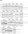
- inventive graphite IE1 surprisingly has a much more stable friction coefficient in most of the sections compared to standard graphite for brake pads and compared to experimental graphite designed for this application.
- a stable friction coefficient is very important in order to have the same brake performance in all conditions, and it also has a beneficial effect on noise reduction (less vibrations induced by unstable friction coefficient), which is a very important feature for electric vehicles. Accordingly, a stable friction coefficient leads to good braking performance and low brake noise.
- the inventive friction material composition comprising IE1 leads to lower heating of the brake disc, which is beneficial (lower risk of degradation, durability) compared to the brake pads prepared using the comparative friction materials. This effect described above for section 14 was observed for most of the sections of performance test SAE J2522 as well.
Landscapes
- Chemical & Material Sciences (AREA)
- Organic Chemistry (AREA)
- Engineering & Computer Science (AREA)
- General Engineering & Computer Science (AREA)
- Life Sciences & Earth Sciences (AREA)
- General Life Sciences & Earth Sciences (AREA)
- Geology (AREA)
- Inorganic Chemistry (AREA)
- Mechanical Engineering (AREA)
- Braking Arrangements (AREA)
Priority Applications (4)
| Application Number | Priority Date | Filing Date | Title |
|---|---|---|---|
| EP23306228.0A EP4495451A1 (de) | 2023-07-17 | 2023-07-17 | Verbesserte reibungsmaterialien |
| KR1020267004182A KR20260042203A (ko) | 2023-07-17 | 2024-07-10 | 개선된 마찰재 |
| PCT/EP2024/069541 WO2025016839A1 (en) | 2023-07-17 | 2024-07-10 | Improved friction materials |
| CN202480047914.5A CN121620652A (zh) | 2023-07-17 | 2024-07-10 | 改进的摩擦材料 |
Applications Claiming Priority (1)
| Application Number | Priority Date | Filing Date | Title |
|---|---|---|---|
| EP23306228.0A EP4495451A1 (de) | 2023-07-17 | 2023-07-17 | Verbesserte reibungsmaterialien |
Publications (1)
| Publication Number | Publication Date |
|---|---|
| EP4495451A1 true EP4495451A1 (de) | 2025-01-22 |
Family
ID=87553950
Family Applications (1)
| Application Number | Title | Priority Date | Filing Date |
|---|---|---|---|
| EP23306228.0A Pending EP4495451A1 (de) | 2023-07-17 | 2023-07-17 | Verbesserte reibungsmaterialien |
Country Status (4)
| Country | Link |
|---|---|
| EP (1) | EP4495451A1 (de) |
| KR (1) | KR20260042203A (de) |
| CN (1) | CN121620652A (de) |
| WO (1) | WO2025016839A1 (de) |
Cited By (1)
| Publication number | Priority date | Publication date | Assignee | Title |
|---|---|---|---|---|
| US12351462B1 (en) | 2024-10-25 | 2025-07-08 | Urbix, Inc. | Graphite shaping and coating devices, systems, and methods |
Citations (6)
| Publication number | Priority date | Publication date | Assignee | Title |
|---|---|---|---|---|
| US933944A (en) | 1909-05-10 | 1909-09-14 | Edward Goodrich Acheson | Method of making pure unctuous graphite. |
| EP0977292A2 (de) | 1998-07-31 | 2000-02-02 | Mitsui Mining Co., Ltd. | Anodenmaterial für Sekundärbatterie, Verfahren zur Herstellung und Lithium-Sekundärbatterie |
| WO2016008951A1 (en) | 2014-07-15 | 2016-01-21 | Imerys Graphite & Carbon Switzerland Ltd. | Hydrophilic surface-modified carbonaceous particulate material |
| EP3088764A1 (de) | 2013-12-24 | 2016-11-02 | Nisshinbo Brake Inc. | Reibungsmaterial |
| EP3131848B1 (de) * | 2014-04-14 | 2018-03-28 | Imerys Graphite & Carbon Switzerland Ltd. | Amorphe kohlenstoffbeschichtung von kohlenstoffhaltigen partikeln aus dispersionen mit amphiphilen organischen verbindungen |
| EP3674371A1 (de) | 2018-12-31 | 2020-07-01 | Imertech Sas | Reibungsmaterial mit graphit, verfahren zur herstellung von reibungsmaterialien und deren verwendungen |
-
2023
- 2023-07-17 EP EP23306228.0A patent/EP4495451A1/de active Pending
-
2024
- 2024-07-10 WO PCT/EP2024/069541 patent/WO2025016839A1/en active Pending
- 2024-07-10 CN CN202480047914.5A patent/CN121620652A/zh active Pending
- 2024-07-10 KR KR1020267004182A patent/KR20260042203A/ko active Pending
Patent Citations (7)
| Publication number | Priority date | Publication date | Assignee | Title |
|---|---|---|---|---|
| US933944A (en) | 1909-05-10 | 1909-09-14 | Edward Goodrich Acheson | Method of making pure unctuous graphite. |
| EP0977292A2 (de) | 1998-07-31 | 2000-02-02 | Mitsui Mining Co., Ltd. | Anodenmaterial für Sekundärbatterie, Verfahren zur Herstellung und Lithium-Sekundärbatterie |
| EP3088764A1 (de) | 2013-12-24 | 2016-11-02 | Nisshinbo Brake Inc. | Reibungsmaterial |
| EP3131848B1 (de) * | 2014-04-14 | 2018-03-28 | Imerys Graphite & Carbon Switzerland Ltd. | Amorphe kohlenstoffbeschichtung von kohlenstoffhaltigen partikeln aus dispersionen mit amphiphilen organischen verbindungen |
| WO2016008951A1 (en) | 2014-07-15 | 2016-01-21 | Imerys Graphite & Carbon Switzerland Ltd. | Hydrophilic surface-modified carbonaceous particulate material |
| EP3674371A1 (de) | 2018-12-31 | 2020-07-01 | Imertech Sas | Reibungsmaterial mit graphit, verfahren zur herstellung von reibungsmaterialien und deren verwendungen |
| CN113227262B (zh) * | 2018-12-31 | 2023-01-31 | 伊梅斯切公司 | 包含石墨的摩擦材料、制造摩擦材料的方法及其用途 |
Non-Patent Citations (5)
| Title |
|---|
| BRUNAUEREMMETTELLER: "Adsorption of Gases in Multimolecular Layers", J. AM. CHEM. SOC., vol. 60, 1938, pages 309 - SI 9 |
| KLUGALEXANDER: "Xray diffraction Procedures", 1967, JOHN WILEY & SONS INC. |
| M. KERKER: "The Scattering of Light and other Electromagnetic Radiation", 1969, ACADEMIC PRESS |
| N. IWASHITAC. RAE PARKH. FUJIMOTOM. SHIRAISHIM. INAGAKI, CARBON, vol. 42, 2004, pages 1227 - 1232 |
| RAVIKOVITCH, P.VISHNYAKOV, A.RUSSO, R.NEIMARK, A., LANGMUIR, vol. 16, 2000, pages 2311 - 2320 |
Cited By (1)
| Publication number | Priority date | Publication date | Assignee | Title |
|---|---|---|---|---|
| US12351462B1 (en) | 2024-10-25 | 2025-07-08 | Urbix, Inc. | Graphite shaping and coating devices, systems, and methods |
Also Published As
| Publication number | Publication date |
|---|---|
| CN121620652A (zh) | 2026-03-06 |
| KR20260042203A (ko) | 2026-03-30 |
| WO2025016839A1 (en) | 2025-01-23 |
Similar Documents
| Publication | Publication Date | Title |
|---|---|---|
| JP6186428B2 (ja) | 摩擦材 | |
| JP7693544B2 (ja) | 黒鉛を含む摩擦材料、摩擦材料の製造方法およびその使用 | |
| JP5540395B2 (ja) | 摩擦材 | |
| US8877339B2 (en) | Sodium hexatitanate and method for production thereof | |
| KR20150031327A (ko) | 마찰재 | |
| EP4495451A1 (de) | Verbesserte reibungsmaterialien | |
| JPWO2003052022A1 (ja) | 摩擦材組成物及び摩擦材組成物を用いた摩擦材 | |
| JP7616804B2 (ja) | 摩擦対 | |
| Bonfanti | Low-impact friction materials for brake pads | |
| JP6254424B2 (ja) | 摩擦材 | |
| WO2019025995A1 (en) | NEW FRICTION MODULATORS AND THEIR USE IN BRAKING DEVICES | |
| CN108018022B (zh) | 摩擦材料 | |
| CN114483843A (zh) | 摩擦材料 | |
| EP4450584A1 (de) | Reibungsmodifikator, reibungsmaterialzusammensetzung, reibungsmaterial und reibungselement | |
| JP2025149095A (ja) | 制輪子及び鉄道車両用踏面ブレーキ装置 | |
| JPH08135701A (ja) | 摩擦材 | |
| JP6676334B2 (ja) | 鉄道車両用摩擦材 | |
| JP7735825B2 (ja) | 摩擦材組成物および摩擦材 | |
| EP4722160A1 (de) | Magnesiumkaliumtitanat, reibungsanpassungsmaterial, reibungsmaterialzusammensetzung, reibungsmaterial und reibungselement | |
| JP2024081464A (ja) | 摩擦材組成物、摩擦材、及び摩擦部材 | |
| JP2022029787A (ja) | 摩擦部材、摩擦材組成物、摩擦材及び車両 | |
| JP2005263823A (ja) | 摩擦材 | |
| JP2022042350A (ja) | ブレーキパッド用複合酸化物粉末、ブレーキパッド用摩擦材組成物、及び、ブレーキパッド用摩擦材 | |
| JP2009155356A (ja) | 摩擦材およびその製造方法 |
Legal Events
| Date | Code | Title | Description |
|---|---|---|---|
| PUAI | Public reference made under article 153(3) epc to a published international application that has entered the european phase |
Free format text: ORIGINAL CODE: 0009012 |
|
| STAA | Information on the status of an ep patent application or granted ep patent |
Free format text: STATUS: THE APPLICATION HAS BEEN PUBLISHED |
|
| AK | Designated contracting states |
Kind code of ref document: A1 Designated state(s): AL AT BE BG CH CY CZ DE DK EE ES FI FR GB GR HR HU IE IS IT LI LT LU LV MC ME MK MT NL NO PL PT RO RS SE SI SK SM TR |
|
| STAA | Information on the status of an ep patent application or granted ep patent |
Free format text: STATUS: REQUEST FOR EXAMINATION WAS MADE |
|
| 17P | Request for examination filed |
Effective date: 20250722 |