EP4491249A2 - Eingabevorrichtung für eine spielkonsole - Google Patents
Eingabevorrichtung für eine spielkonsole Download PDFInfo
- Publication number
- EP4491249A2 EP4491249A2 EP24214622.3A EP24214622A EP4491249A2 EP 4491249 A2 EP4491249 A2 EP 4491249A2 EP 24214622 A EP24214622 A EP 24214622A EP 4491249 A2 EP4491249 A2 EP 4491249A2
- Authority
- EP
- European Patent Office
- Prior art keywords
- controller
- face
- user
- control
- case
- Prior art date
- Legal status (The legal status is an assumption and is not a legal conclusion. Google has not performed a legal analysis and makes no representation as to the accuracy of the status listed.)
- Withdrawn
Links
Images




Classifications
-
- A—HUMAN NECESSITIES
- A63—SPORTS; GAMES; AMUSEMENTS
- A63F—CARD, BOARD, OR ROULETTE GAMES; INDOOR GAMES USING SMALL MOVING PLAYING BODIES; VIDEO GAMES; GAMES NOT OTHERWISE PROVIDED FOR
- A63F13/00—Video games, i.e. games using an electronically generated display having two or more dimensions
- A63F13/20—Input arrangements for video game devices
- A63F13/24—Constructional details thereof, e.g. game controllers with detachable joystick handles
-
- A—HUMAN NECESSITIES
- A63—SPORTS; GAMES; AMUSEMENTS
- A63F—CARD, BOARD, OR ROULETTE GAMES; INDOOR GAMES USING SMALL MOVING PLAYING BODIES; VIDEO GAMES; GAMES NOT OTHERWISE PROVIDED FOR
- A63F13/00—Video games, i.e. games using an electronically generated display having two or more dimensions
- A63F13/25—Output arrangements for video game devices
- A63F13/28—Output arrangements for video game devices responding to control signals received from the game device for affecting ambient conditions, e.g. for vibrating players' seats, activating scent dispensers or affecting temperature or light
- A63F13/285—Generating tactile feedback signals via the game input device, e.g. force feedback
-
- A—HUMAN NECESSITIES
- A63—SPORTS; GAMES; AMUSEMENTS
- A63F—CARD, BOARD, OR ROULETTE GAMES; INDOOR GAMES USING SMALL MOVING PLAYING BODIES; VIDEO GAMES; GAMES NOT OTHERWISE PROVIDED FOR
- A63F13/00—Video games, i.e. games using an electronically generated display having two or more dimensions
- A63F13/40—Processing input control signals of video game devices, e.g. signals generated by the player or derived from the environment
- A63F13/42—Processing input control signals of video game devices, e.g. signals generated by the player or derived from the environment by mapping the input signals into game commands, e.g. mapping the displacement of a stylus on a touch screen to the steering angle of a virtual vehicle
- A63F13/428—Processing input control signals of video game devices, e.g. signals generated by the player or derived from the environment by mapping the input signals into game commands, e.g. mapping the displacement of a stylus on a touch screen to the steering angle of a virtual vehicle involving motion or position input signals, e.g. signals representing the rotation of an input controller or a player's arm motions sensed by accelerometers or gyroscopes
-
- A—HUMAN NECESSITIES
- A63—SPORTS; GAMES; AMUSEMENTS
- A63F—CARD, BOARD, OR ROULETTE GAMES; INDOOR GAMES USING SMALL MOVING PLAYING BODIES; VIDEO GAMES; GAMES NOT OTHERWISE PROVIDED FOR
- A63F13/00—Video games, i.e. games using an electronically generated display having two or more dimensions
- A63F13/90—Constructional details or arrangements of video game devices not provided for in groups A63F13/20 or A63F13/25, e.g. housing, wiring, connections or cabinets
- A63F13/98—Accessories, i.e. detachable arrangements optional for the use of the video game device, e.g. grip supports of game controllers
-
- A—HUMAN NECESSITIES
- A63—SPORTS; GAMES; AMUSEMENTS
- A63F—CARD, BOARD, OR ROULETTE GAMES; INDOOR GAMES USING SMALL MOVING PLAYING BODIES; VIDEO GAMES; GAMES NOT OTHERWISE PROVIDED FOR
- A63F2300/00—Features of games using an electronically generated display having two or more dimensions, e.g. on a television screen, showing representations related to the game
- A63F2300/10—Features of games using an electronically generated display having two or more dimensions, e.g. on a television screen, showing representations related to the game characterized by input arrangements for converting player-generated signals into game device control signals
- A63F2300/1043—Features of games using an electronically generated display having two or more dimensions, e.g. on a television screen, showing representations related to the game characterized by input arrangements for converting player-generated signals into game device control signals being characterized by constructional details
Definitions
- the present invention relates to an input apparatus for a computer, such as, but not limited to, a games console, more particularly, but not exclusively the invention relates to, a hand held controller for a games console.
- Controllers for most current games consoles are generally intended to be held and operated by the user holding the controller in both hands, such controllers are sometime referred to as "gamepads".
- a conventional controller will generally comprise a hard outer case with a plurality of controls mounted about the controller. Typically the controls include buttons, analogue control sticks, bumpers and triggers and are provided upon the front or the top of the controller.
- An object of the present invention is to provide a controller having at least one additional control mounted to the controller. It is desirable that the controller is ergonomic, that a user can comfortably operate the control. It is also desirable that the additional control is readily accessible.
- the present invention seeks to overcome or at least mitigate the problems of the prior art.
- a first aspect of the present disclosure provides an input apparatus for a computer comprising an outer case having a front face, a top face and opposing side walls, the apparatus comprising at least one control located on the top face of the controller, the controller being shaped to be held in both hands of a user such and the user's index fingers are positioned to operate the at least one control located on the top of the controller; the controller further comprises at least one additional control located on at least one of the opposing side walls of the controller in a position operable by an intermediate portion of the user's index finger.
- At least one additional control comprises a switch mechanism disposed in an interior of the outer case.
- At least one additional control comprises an actuator pivotally mounted in cradle disposed within the interior of the outer case.
- At least one additional control comprises a trunnion mounted in the cradle, the cradle comprising a first portion provided by a portion of the outer case and a second portion provided by a chassis member.
- At least one additional control comprises at least one limb coupling the trunnion to a body portion.
- the body portion extends through an opening in the outer case.
- a cover is mounted to the body portion and wherein at least a portion of the cover extends through the opening in the outer case.
- At least one additional control comprises a sensor mounted to said one of the opposing side walls of the controller.
- the at least one additional control is disposed proximate the at least one control located on the top of the controller.
- the input apparatus is a hand held controller for a games console and further comprises:
- a second aspect of the present disclosure provides an input apparatus for a computer comprising an outer case having a front face, a top face and opposing side walls, the apparatus comprising at least one control located on the top face of the controller, the controller being shaped to be held in both hands of a user such and the user's index fingers are positioned to operate the at least one control located on the top of the controller; the controller further comprises at least one additional control located on at least one of the opposing side walls of the controller, the at least one additional control being disposed proximate at least one control located on the top of the controller.
- a third aspect of the present disclosure provides a hand held controller for video games console comprising an outer case having a front face, a top face and opposing side walls, the apparatus comprising at least one control located on the top face of the controller, the controller being shaped to be held in both hands of a user such and the user's index fingers are positioned to operate the at least one control located on the top of the controller; the controller further comprises at least one additional control located on at least one of the opposing side walls of the controller, the at least one additional control being disposed proximate at least one control located on the top of the controller.
- a fourth aspect of the present disclosure provides an input apparatus for a computer comprising an outer case having a front face and a top face and having a plurality of controls located on the front face and the top face of the controller; the controller being shaped to be held in both hands of a user such that the user's thumbs are positioned to operate controls located on the front of the controller and the user's index fingers are positioned to operate controls located on the top of the controller wherein the controller comprises a front panel mounted to a chassis member, the chassis member comprising at least one chamber, the chamber comprising an electrical connector for coupling to an electrical device mountable in the chamber, wherein the chamber is provided in a handle on the controller.
- a fifth aspect of the present disclosure provides input apparatus for a computer comprising an outer case having a front face and a top face and having a plurality of controls located on the front face and the top face of the controller; the controller being shaped to be held in both hands of a user such that the user's thumbs are positioned to operate controls located on the front of the controller and the user's index fingers are positioned to operate controls located on the top of the controller wherein the controller comprises a front panel detachably mounted to a chassis member, the chassis member comprising at least one chamber, the chamber comprising a removable haptic feedback module.
- the controller comprise a first handle and a second handle, and a first chamber is provided in the first handle and a second chamber is provided in the second chamber, each of the first and second chambers comprising a removable haptic feedback module.
- the removable haptic feedback module is mounted in a housing, and comprises at least one first electrical contact in electrical communication with at least one second electrical contact mounted in a wall of the chamber.
- the input apparatus comprises a back panel mounted to the chassis member.
- a sixth aspect of the present disclosure provides an input apparatus for a computer comprising an outer case having a front face and a top face and having a plurality of controls located on the front face and the top face of the controller; the controller being shaped to be held in both hands of a user such that the user's thumbs are positioned to operate controls located on the front of the controller and the user's index fingers are positioned to operate controls located on the top of the controller wherein the controller comprises a front panel detachably mounted to a chassis member, the chassis member comprising at least one chamber having at least one first electrical contact mounted in a wall of the chamber, the chamber comprising a removable module, the module comprising a housing, having at least one second electrical contact in electrical communication with at least one first electrical contact.
- the controller comprises a first handle and a second handle, and a first chamber is provided in the first handle and a second chamber is provided in the second chamber, each of the first and second chambers comprising a removable module.
- a seventh aspect of the present disclosure provides a removable haptic feedback module for use with an input apparatus for a computer comprising:
- An eighth aspect of the present disclosure provides an input apparatus for a computer comprising an outer case having a front face and a top face and having a plurality of controls located on the front face and the top face of the controller; the controller being shaped to be held in both hands of a user such that the user's thumbs are positioned to operate controls located on the front of the controller and the user's index fingers are positioned to operate controls located on the top of the controller wherein the controller comprises a first handle module detachably mounted to a chassis member, the first handle module comprising at least one chamber having electrical device disposed therein, first handle module comprises a fastening mechanism for mounting first handle module to the chassis member.
- the first handle module comprises haptic feedback device.
- the first handle module is in electrical communication with one or more electrical components mounted to the chassis member.
- the controller comprises a second handle module detachably mounted to a chassis member, the second handle module comprising at least one chamber having electronic device disposed therein, second handle module comprises a fastening mechanism for mounting second handle module to the chassis member.
- a ninth aspect of the present disclosure provides a removable handle module for use with an input apparatus for a computer comprising:
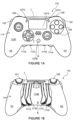
- FIG. 1A there is shown a plan view from above of the front of an input apparatus 110 for a use with a computer.
- the input apparatus 110 illustrated takes the form of a controller 110 or game pad 110 for use with a video games console or similar.
- the input apparatus 10 may take the form of a handheld games console or other mobile device such as but not limited to a smartphone, tablet computer, phablet or the input apparatus 110 may be an accessory device (such as, but not limited to, a sleeve or case) for use with such a mobile device.
- the apparatus or controller 110 comprises an outer case or shell 114.
- the case 114 may comprise one or more panels fitted together and or mounted to a chassis member.
- the case 114 may comprise a front body panel 114F and a rear body panel 114B (see Figure 1B ).
- the outer case 114 comprises a void in which electronic components (such as, but not limited to, switches 138 and/or sensors, see Figure 5 ) are located.
- the apparatus or controller 110 comprises a plurality of controls which are mounted to the front F and to the top T of the controller 110.
- the term “front” refers to an upper surface of the controller 110 when in normal use held in both hands, whilst the term “top” refers to a leading edge of the controller 110 which typically faces away from a user when held in both hands.
- a rear or back R of the controller opposes the "front” and typically will form a lower surface, whilst the term “bottom” B refers to a trailing edge of the controller 110 which typically faces towards the user when held in both hands.
- the controller 110 comprises a plurality of buttons which when activated initiate a specific action or control function.
- the controller 110 comprises at least one omnidirectional control stick or button which is operable to provide directional input.
- the controller 110 comprises first, left, and second, right, analogue control sticks, also known as thumb sticks 102, 103.
- the first left 102 and second right 103 thumb sticks normally control movement and are intended to be operated by the user's left and right thumbs respectively.
- Left and right thumb sticks 102, 103 are mounted to the front face F of the controller 110.
- the left thumb stick 102 is located in a forward (or upper i.e. nearer the top T of the controller 110) left region of the front face F; and right thumb stick 103 is located in a rearward (or lower i.e. nearer the bottom B of the controller 110) right region of the front face F.
- buttons 104 normally control additional actions and are intended to be operated by the user's right thumb.
- the direction pad 105 is intended to be operated by the user's left thumb, typically either as an alternative to the left thumb stick 102 or to provide additional action controls.
- a left shoulder button or bumper 108 and a right shoulder button or bumper 109 are located on the top face T of the controller 110.
- a left trigger 106 and a right trigger 101 are also located on the top face T of the controller 10 (see Figure 1B ).
- the left and right triggers 106, 101 are typically operated by a user's index fingers.
- the left and right bumpers 8, 9 may also be operated by a user's index fingers.
- the left and right triggers 106, 101 may be analogue in nature, or may comprise a plurality of discrete digital states, that is to say the input control may be dependent upon the degree of depression or displacement of the trigger body.
- the controller 110 may comprise one or more additional input buttons 107A, 107B, 107C, the buttons 107A, 107B, 107C may take the form of one or more digital or analogue buttons, or may be in the form of a touch pad or touch screen.
- buttons 104 In order to operate any of the buttons 104 a user will normally remove their right thumb from the right thumb stick 103 so as to depress one or more of the buttons 104. Switching between the right thumb stick 103 and the buttons 104 takes time since the user's thumb must traverse the distance therebetween. This may also cause a loss of, or reduction in, control in some games because the user has to relinquish control over the right thumb stick 103 in order to control the buttons 104. This may be a particular problem in games where the right thumb stick 103 is used for aiming. A similar problem may arise in games where the direction pad 105 provides additional actions and the user has to remove their left thumb from the left thumb stick 102 in order to operate the direction pad 105.
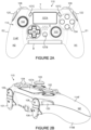
- the controller 110 may comprise one or more additional controls 111A, 111B, 111C, 111D mounted to the rear R or back of the apparatus 110, where the rear R or back face is opposite the top face F (the face F to which the buttons 104, left and right thumb sticks 102, 103 and direction pad 105 are mounted).
- the apparatus comprises four additional controls 111A, 111B, 111C, 111D. In other embodiments, more or fewer additional controls 111A, 111B, 111C, 111D may be provided.
- the additional controls 111A, 111B, 111C, 111D also referred to herein as paddle levers.
- Each may comprise an elongate member, that is to say the member comprises a first end and a second end the distance between the first and second ends is greater than a width of the member.
- the member may be bent, twisted or folded in one or more directions.
- the paddle levers 111A, 111B, 111C, 111D may be orientated such that at least a portion of the member is substantially parallel with respect to one of a first and second handle portions H1, H2 of the controller 110.
- the members are each positioned to be operable by the middle, ring or little fingers of a user. These are the fingers normally used to grasp first and second handle portion H1, H2 which thus brings them into proximity with the rear face R of the controller 110.
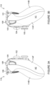
- the user can operate either the left shoulder button 108 or left trigger 106 with the index finger D2 of their left hand and can operate either the right shoulder button 109 or right trigger 101 with the index finger D2 of their right hand (see Figure 1C ).
- the user may place the pad of the end of their index fingers on the controls on the top of the controller 110. When doing so the user index fingers may leave a gap G between side walls E1, E2 of the controller case 114 and the adjacent index finger D1, D2.
- the present disclosure provide an actuator or additional control 120, 122 upon at least one of the side walls E1, E2 of the controller case 114 proximate the top or leading edge T of the controller 110.
- the additional controls 120, 122 may be disposed in an upper region of the side walls E1, E2 of the controller case 114m that is to say proximate the front F of the controller 110.
- the additional controls 120, 122 are disposed in the crook of a respective one of the index fingers D1, D2, the additional controls 120, 122 may at least partially fill the gaps G.
- the additional control 120, 122 are arranged to be operated by a user engaging or pressing the control with one of the phalanges of the index finger D1, D2, preferably the user's proximal phalanx or rather the fleshy part thereabout.
- the additional control 120, 122 may be operated by the middle phalanx of the index finger D1, D2. This may be more common when the users hand is smaller in size.
- the additional controls 120, 122 are operable by an intermediate portion of the user's index finger, wherein the intermediate portion is disposed between the finger pad or end of the finger and the metacarpophalangeal joint.
- the additional controls 120, 122 may be operated by a straightening action of the index finger D1, D2. In this way the user's proximal phalanx is brought towards the additional control 120, 122 so as to activate the control 120, 122.
- the user may operate the additional controls 120, 122 when their index finger D1, D2 is at rest upon or aligned with the shoulder button 108, 109 or 122 or when their index finger D1, D2 is at rest upon or aligned with the triggers 101, 106.
- the user may operate the additional controls 120, 122 without altering the alignment of their index finger with whichever of the front controls, shoulder button or trigger, that their index finger is poised over.
- the additional control 120 may replicate the function operated by either the left shoulder button 108 or left trigger 106.
- the additional control 120 may replicate the function of one of the controls disposed on the front of the controller 110 for example, but not limited to, buttons 104.
- the additional control 122 may replicate the function operated by either the right shoulder button 109 or right trigger 101.
- the additional control 122 may replicate the function of one of the controls disposed on the front of the controller 110 for example, but not limited to, buttons 104.
- the additional controls 120, 122 may control a new command functions.
- activation of one of the additional controls 120, 122 may change the command function or operation initiated by one of the other controls provided on the controller.
- activation of one of the additional controls 120, 122 may change the command function or operation initiated by one of the other controls provided on the controller.
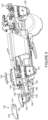
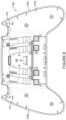
- Figure 5 to 10 show further views of the additional controls 120, 122 and a mounting structure.
- the additional controls are substantially similar in construction albeit mirror images of each other.
- Figure 5 and 6 are exploded views of the second additional control 122.
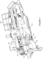
- Figure 7 is a perspective view of a partially assembled first addition control 120.
- the additional controls comprise a main body 132 and a pin or shaft forming a trunnion 140.
- the trunnion 140 is coupled to the main body 132 by at least one limb 134, 136.
- the illustrated embodiment comprises a pair of limbs.
- the limbs 134, 136 are mounted to opposing ends of the trunnion 140 and to a base of the main body 132.
- the limbs 134, 136 are crooked or nonlinear.
- the limbs 134, 136 may be arcuate or substantially "L" shaped. In this way the trunnion 140 is offset from the main body 132 in a vertical direction and in a horizontal direction.
- the vertical direction is a first direction which extends between the front F and the back B of the controller 110, irrespective of the actual orientation of the controller 110.
- the horizontal direction is a second direction which extends between side walls E1, E2 of the controller 110, irrespective of the actual orientation of the controller 110.
- the controller 110 comprises a chassis 146 to which the triggers 101, 106 are mounted.
- a circuit board 144 is mounted to the chassis 142.
- the circuit board 144 comprises a plurality of electrical or electronic components mounted thereto.
- a first switch 138 is mounted to the circuit board 144, the additional control 122 is arranged to activate the first switch 138 to initiate a command function associated therewith.
- the first switch is mounted orthogonally to the circuit board 144. In one embodiment a right angle Tact Switch may be employed.
- the chassis 146 comprises a first or upper portion 142 of a cradle in which the trunnion 140 is mounted.
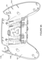
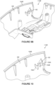
- the back case panel 114B comprises a second or base portion 152 of the cradle, see Figures 8 to 10 .
- the cradle is arranged to be disposed below the switch 138. That is to say the switch 138 and cradle are disposed on opposing sides of the circuit board 144.
- the main body 132 may comprise a protuberance or projection 145 arranged to interact with an actuator of the switch 138.
- the additional control 122 may comprise a cover 130 mounted to the main body 132.
- the cover 130 may be mounted to the main body by a clip or fastening mechanism 147/149 such as but not limited to a latch mechanism comprising a latch 149 and a receiver 147. In other embodiments other fastening mechanism may be employed.
- Providing a cover 130 readily allows one or more characteristics of the external portion of the addition control 120, 122 to be customised such as, but not limited to, the shape, size, colour, appearance, material or texture.
- the trunnion In an assembled condition the trunnion is at rest in the base portion 152 of the cradle provided by the back case panel 114B.
- the upper portion 142 of the cradle provided by the chassis 146 is disposed over the trunnion 140 so as to retain the trunnion in the cradle.
- the base portion of the cradle 152 may be provided by at least one support 152A, 152B, 152C extending from an internal surface of the back case panel 114B into the interior of the back case panel 114B.
- the base portion of the cradle 152 may be provided by a recess 153 provided in a side or base wall of the back case panel 114B.
- the switch mechanism 138 and control actuator 120, 122 may be replaced with a sensor mounted on the side walls E1, E2 of the controller 110 in same the location as the control actuators 120, 122.
- the sensor may take the form of a capacitive or resistive touch pad. In other embodiments it may be an optical sensor.
- the sensor may be arranged to be substantially flush with the outer surface of the controller side walls. This may reduce the likelihood of accidental activation of the additional control 120, 122.
- the sensor may be activated by bringing the users finger into close proximity of touching contact with the sensor.
- FIG 11 there is shown an alternative embodiment of the present disclosure.
- the alternative embodiment shares many common features with the first embodiment and therefore only the differences from the embodiment illustrated in Figures 1A to 10 will be described in any greater detail.
- FIG 11 illustrates an exploded view from above of an alternative input apparatus or controller 110 for a use with a computer.
- the controller 110 comprises first, left, and second, right, analogue control sticks, also known as thumb sticks 102, 103, which normally control movement and are intended to be operated by the user's left and right thumbs respectively, left and right thumb sticks are mounted to the front face of the controller 110, the left thumb stick is located in rearward (or lower -nearer the bottom face of the controller 110) left region of the front face and right thumb stick is located in forward (or upper -nearer the top face of the controller 110) right region of the front face.
- buttons 104 located on a forward (or upper -nearer the top face of the controller 110) left portion of the front face of the controller 10, which normally control additional actions and are intended to be operated by the user's left thumb.
- buttons 104 located on a forward (or upper -nearer the top face of the controller 110) left portion of the front face of the controller 10, which normally control additional actions and are intended to be operated by the user's left thumb.
- There is a direction pad 105 located on the rearward (or lower) right portion of the front face of the controller 110.
- the direction pad 105 is intended to be operated by the user's right thumb, typically either as an alternative to the right thumb stick 103 or to provide additional actions.
- a left shoulder button or bumper and a right shoulder button or bumper are located on the top face of the controller 110.
- a left trigger and a right trigger are also located on the top face of the controller 110.
- the left and right triggers are typically operated by a user's index fingers.
- the left and right bumpers may also be operated by a user's index fingers.
- the left and right triggers may analogue in nature, or may comprise a plurality of discrete digital states, that is to say the input control is dependent upon the degree of depression or displacement of the trigger body.
- the controller comprises at least one paddle lever control 111A, 111B, 111C, 111D mounted to the back of the controller 110 substantially as described with reference to the embodiment of Figures 1A to 10 .
- the controller comprises at least one additional index finger control 122 mounted to the side walls of the controller 110 substantially as described with reference to the embodiment of Figures 1A to 10 .
- the controller 110 comprises a chassis or frame member 114C to which a front case panel 114F and rear case panel 114b are mounted.
- the frame member 114C comprises a first chamber C1 arranged to be disposed in the first handle portion H1 of the controller 110.
- the frame member 114C comprises a second chamber C2 arranged to be disposed in the second handle portion H2 of the controller 110.
- the first chamber C1 and second chamber C2 are substantially the same in construction and will be described by reference to the second chamber C2.
- the second chamber C2 defines at least in part a void V for receiving a removable module 160 in the form of a haptic feedback module.
- the haptic feedback module may take the form of a rumble or vibration module.
- the vibration module comprises an electric motor having an eccentric weight mounted to a drive shaft. Rotation of the motor causes the user to experience vibrations as the eccentric weight is moved.
- the removable module 160 comprises a housing comprising a base 163 having bottom wall, opposed side walls and opposed end walls defining an interior I and a lid 161 forming a top wall.
- the lid is mounted to the base 163 by a fastening mechanism such as, but not limited to, a latch mechanism 164.
- the vibration module is mounted in the interior of the housing.
- the removable module 160 comprises at least one first electrical contact for electrical communication with at least one second electrical contact provided in the first or second chamber C1, C2.
- the at least one first electrical contact may be formed by one or more pins or spring contacts passing though apertures in the housing. Each of the at least one first electrical contacts may be resiliently biased to maintain electrical engagement with one of the at least one second electrical contacts.
- the controller 110 may comprise a securing mechanism for holding the haptic feedback module 160 in the respective one of the first and second chambers C1, C2.
- the securing mechanism may be mechanical such as releasable catch or may be magnetic in nature.
- the securing mechanism may be omitted the removable haptic feedback module 160 may employ a friction or interference fit in the respective one first and second chambers C1, C2.
- a finger recess 168 may be provided to facilitate removal of the haptic feedback modules 160 from the frame member 114C.
- the front case panel 114F may be detachably mounted to the frame member 114C.
- first and second chambers C1, C2 may be employed as storage compartments for example for holding interchangeable component parts of the controller 110 such as, but not limited to, a thumbstick stalk or actuator, a D-pad actuator, a paddle lever.
- first and second chambers C1, C2 may be employed to provide one or more additional electronic devices for example, but not limited to an additional or supplementary battery, wireless communication device, sensors such as but not limited to accelerometers, gyroscopes, GPS sensor, audio speakers, microphones.
- sensors such as but not limited to accelerometers, gyroscopes, GPS sensor, audio speakers, microphones.
- the back case panel 114B may be detachable and the first and second chambers C1, C2 may be accessed by removal of at least a part of the back case panel 114B.
- the controller 110 may comprise access panels provided on at least one of the front, back or sides of the controller which are removable from the controller 110 so as to enable a user to access the first and second chambers C1, C2.
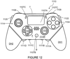
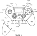
- FIG. 12 and 13 there is shown an alternative embodiment of the present disclosure.
- like numerals have, where possible, been used to denote like parts, albeit with the addition of the prefix "1000" and so on to indicate that these features belong to the third embodiment.
- the alternative embodiment shares many common features with the first and second embodiments and therefore only the differences from the embodiment illustrated in Figures 1A to 11 will be described in any greater detail.
- Figures 12 and 13 illustrate a plan views from above of an alternative input apparatus or controller 1110 for a use with a computer.
- the controller 1110 comprises a plurality of controls mounted thereto.
- the plurality of controls include a first, left, and a second, right, analogue control sticks, also known as thumb sticks 1102, 1103, which normally control movement and are intended to be operated by the user's left and right thumbs respectively, left and right thumb sticks are mounted to the front face of the controller 1110.
- thumb sticks 1102, 1103 also known as thumb sticks 1102, 1103
- thumb sticks 1102 which normally control movement and are intended to be operated by the user's left and right thumbs respectively
- left and right thumb sticks are mounted to the front face of the controller 1110.
- There is a direction pad 1105 located on the front face of the controller 1110.
- the direction pad 1105 is intended to be operated by the user's right thumb, typically either as an alternative to the right thumb stick 1103 or to provide additional actions.
- a left shoulder button or bumper and a right shoulder button or bumper are located on the top face of the controller 1110.
- a left trigger and a right trigger are also located on the top face of the controller 1110.
- the left and right triggers are typically operated by a user's index fingers.
- the left and right bumpers may also be operated by a user's index fingers.
- the left and right triggers may analogue in nature, or may comprise a plurality of discrete digital states, that is to say the input control is dependent upon the degree of depression or displacement of the trigger body.
- the controller comprises at least one paddle lever control 1111A, 1111B, 1111C, 1111D mounted to the back of the controller 1110.
- the controller comprises at least one additional index finger control 1120, 1122 mounted to the side walls of the controller 1110 substantially as described with reference to the embodiment of Figures 1A to 10 .
- the controller 1110 comprises a chassis or frame member 1114M to which a first, right, handle module DH1 and a second left handle module DH2 are detachably mounted.
- the plurality of controls are mounted to chassis member 1114M.
- the first handle module DH1 comprises a first chamber or interior.
- the second handle module DH2 comprises a second chamber or interior.
- the first chamber C1 and second chamber C2 each define at least in part a void V for receiving an electronic device.
- the electronic device provides an additional or supplementary feature to the controller for example but not limited to a removable haptic feedback module.
- the haptic feedback module may take the form of a rumble or vibration module.
- the vibration module comprises an electric motor having an eccentric weight mounted to a drive shaft. Rotation of the motor causes the user to experience vibrations as the eccentric weight is moved.
- the first and second handle modules DH1, DH2 each comprise a fastening mechanism 170, in the illustrated embodiment the fastening mechanism takes the form of a clip or latch mechanism, in other embodiments other mechanisms may be employed such as, but not limited to screw thread such as screws or bolts, bayonet fitting, magnets,
- the first and second handle modules DH1, DH2 each comprise an electrical connector 172 such that the electronic device disposed therein is in electrical communication with electrical component disposed in, or mounted to, the frame member 1114M.
- the electrical connector 172 mates or couples with a complementary connector (not shown) mounted to the frame member 1114M.
- a release mechanism (not shown) may be provided to release the first and second handle modules DH1, DH2 from the frame member 1114M.
- a finger recess may be provided to facilitate removal of first and second handle modules DH1, DH2 from the frame member 1114M.
- the first and second handle modules DH1, DH2 may be employed to provide one or more additional features for example, but not limited to an additional or supplementary battery, wireless communication device, sensors such as but not limited to accelerometers, gyroscopes, GPS sensor, audio speakers, microphones, wireless charging module.
- sensors such as but not limited to accelerometers, gyroscopes, GPS sensor, audio speakers, microphones, wireless charging module.
- the size and shape of the paddles may be adjusted to accommodate controllers of differing size or shape.
- the microswitches may be replaced with a magnetic switch or sensor, for example a reed switch or hall sensor; the paddles may comprise a magnet arranged so as to activate the magnetic switch or sensor when the paddle is depressed by a user.
- the magnetic switch or sensor is mounted inside the controller behind the back panel and that there will be no requirement to provide apertures through the back panel in order that the paddles can physically contact the microswitches.
- the user may be provided with feedback to indicate that the switch has been activated.
- the feedback may be aural or haptic, for example, such as an audible click.
- controllers may be coupled to a games console or computer by a wired connection or by a wireless connection device.
- the controller may be constructed as a shell or caddy into which a hand-held electronic device such as, but not limited to, a mobile telephone (smartphone) or tablet computer is inserted, the caddy comprising control actuators, thumb sticks and/or buttons (which are coupled to the electronic device either wirelessly or via physical or wired connection) for interaction with or control of the electronic device.
- a hand-held electronic device such as, but not limited to, a mobile telephone (smartphone) or tablet computer
- the caddy comprising control actuators, thumb sticks and/or buttons (which are coupled to the electronic device either wirelessly or via physical or wired connection) for interaction with or control of the electronic device.
Landscapes
- Engineering & Computer Science (AREA)
- Multimedia (AREA)
- Human Computer Interaction (AREA)
- User Interface Of Digital Computer (AREA)
- Position Input By Displaying (AREA)
Applications Claiming Priority (3)
| Application Number | Priority Date | Filing Date | Title |
|---|---|---|---|
| US201762518239P | 2017-06-12 | 2017-06-12 | |
| PCT/GB2018/051585 WO2018229466A2 (en) | 2017-06-12 | 2018-06-11 | Input apparatus for a games console |
| EP18732453.8A EP3638384B1 (de) | 2017-06-12 | 2018-06-11 | Eingabevorrichtung für eine spielkonsole |
Related Parent Applications (1)
| Application Number | Title | Priority Date | Filing Date |
|---|---|---|---|
| EP18732453.8A Division EP3638384B1 (de) | 2017-06-12 | 2018-06-11 | Eingabevorrichtung für eine spielkonsole |
Publications (2)
| Publication Number | Publication Date |
|---|---|
| EP4491249A2 true EP4491249A2 (de) | 2025-01-15 |
| EP4491249A3 EP4491249A3 (de) | 2025-03-26 |
Family
ID=62683364
Family Applications (2)
| Application Number | Title | Priority Date | Filing Date |
|---|---|---|---|
| EP24214622.3A Withdrawn EP4491249A3 (de) | 2017-06-12 | 2018-06-11 | Eingabevorrichtung für eine spielkonsole |
| EP18732453.8A Active EP3638384B1 (de) | 2017-06-12 | 2018-06-11 | Eingabevorrichtung für eine spielkonsole |
Family Applications After (1)
| Application Number | Title | Priority Date | Filing Date |
|---|---|---|---|
| EP18732453.8A Active EP3638384B1 (de) | 2017-06-12 | 2018-06-11 | Eingabevorrichtung für eine spielkonsole |
Country Status (4)
| Country | Link |
|---|---|
| US (2) | US11103775B2 (de) |
| EP (2) | EP4491249A3 (de) |
| CN (1) | CN110740794A (de) |
| WO (1) | WO2018229466A2 (de) |
Families Citing this family (21)
| Publication number | Priority date | Publication date | Assignee | Title |
|---|---|---|---|---|
| GB2567634B (en) * | 2017-10-17 | 2021-08-25 | Sony Interactive Entertainment Inc | Input apparatus and method |
| US10471345B1 (en) * | 2019-02-08 | 2019-11-12 | Arkade, Inc. | Pedal system for gaming apparatus |
| CN110559652A (zh) * | 2019-09-10 | 2019-12-13 | 深圳市七熊科技有限公司 | 一种多摇杆的游戏手柄 |
| JP7353912B2 (ja) | 2019-10-17 | 2023-10-02 | 任天堂株式会社 | 入力装置、ゲームコントローラ、情報処理装置 |
| USD920341S1 (en) * | 2019-11-21 | 2021-05-25 | Marketing Instincts Inc. | Skin cover set for a game controller |
| CN121714910A (zh) * | 2020-03-31 | 2026-03-24 | 索尼互动娱乐股份有限公司 | 输入设备 |
| JP7516091B2 (ja) * | 2020-03-31 | 2024-07-16 | 株式会社ソニー・インタラクティブエンタテインメント | 入力デバイス及びカバー |
| WO2022118000A1 (en) * | 2020-12-01 | 2022-06-09 | Ironburg Inventions Limited | Input apparatus for a games console |
| JP7431350B2 (ja) | 2020-12-17 | 2024-02-14 | 任天堂株式会社 | 入力装置、ゲームコントローラ、情報処理装置 |
| USD984464S1 (en) * | 2020-12-22 | 2023-04-25 | Google Llc | Display screen or portion thereof with graphical user interface |
| CN215769661U (zh) * | 2021-02-10 | 2022-02-08 | 斯特赖克虚拟现实技术有限公司 | 包括提供触觉反馈的外围设备的仿真系统 |
| US12541197B2 (en) * | 2021-07-23 | 2026-02-03 | Yawman LLC | Controlling simulated and physical vehicles with handheld devices |
| USD992645S1 (en) | 2021-07-23 | 2023-07-18 | Yawman LLC | Handheld controller for a flight simulator or a remotely controlled aircraft |
| US11868125B2 (en) | 2021-07-23 | 2024-01-09 | Yawman LLC | Controlling simulated and remotely controlled flyable aircraft with handheld devices |
| US11836291B1 (en) * | 2021-09-07 | 2023-12-05 | University Of North Florida Board Of Trustees | Apparatus and method for developmental and/or rehabilitative sensory substitution |
| WO2023127658A1 (ja) * | 2021-12-28 | 2023-07-06 | 株式会社ソニー・インタラクティブエンタテインメント | 入力デバイス |
| USD983273S1 (en) * | 2023-01-03 | 2023-04-11 | Luosheng Hu | Game controller back paddles |
| TWI826324B (zh) * | 2023-05-19 | 2023-12-11 | 寶德科技股份有限公司 | 手機的控制把手套件 |
| CN116510320A (zh) * | 2023-07-05 | 2023-08-01 | 深圳市莱仕达电子科技有限公司 | 一种可调节反馈力度的手柄 |
| DE102024124129A1 (de) * | 2024-05-09 | 2025-11-13 | Dexin Corporation | Bediengriffsatz |
| US20260021385A1 (en) * | 2024-07-17 | 2026-01-22 | Nintendo Co., Ltd. | Game controller |
Family Cites Families (113)
| Publication number | Priority date | Publication date | Assignee | Title |
|---|---|---|---|---|
| US4032728A (en) | 1974-12-20 | 1977-06-28 | Olympia Werke Ag | Push button switch |
| US4786768A (en) | 1987-08-20 | 1988-11-22 | Interlock | Manual cursor actuator for electronic keyboards |
| GB2244546A (en) | 1990-05-10 | 1991-12-04 | Primax Electronics Ltd | Computer input device |
| DE69315149T2 (de) * | 1992-09-09 | 1998-05-07 | Matsushita Electric Ind Co Ltd | Kombinations-Druckschalter-Anordnung |
| DE69507767T2 (de) | 1994-05-20 | 1999-09-02 | Sega Enterprises | Handsteuergerät für videospiel |
| US5451053A (en) | 1994-09-09 | 1995-09-19 | Garrido; Fernando P. | Reconfigurable video game controller |
| US5773769A (en) | 1994-11-23 | 1998-06-30 | Raymond; Christopher W. | Twin lever key with horizontal finger pads for code transmission |
| GB2295662A (en) * | 1994-11-28 | 1996-06-05 | Wah Leung Chan | Joystick eg for video games |
| JPH0973363A (ja) | 1995-09-06 | 1997-03-18 | Sega Enterp Ltd | 操作入力装置 |
| KR100501144B1 (ko) | 1996-03-05 | 2005-07-18 | 가부시키가이샤 세가 | 조작 입력 장치 및 이를 사용하는 전자 장치 |
| JPH1020951A (ja) | 1996-07-02 | 1998-01-23 | Sega Enterp Ltd | 多段階トリガー装置 |
| US5883690A (en) | 1997-05-30 | 1999-03-16 | Z-Products | Joystick adapter for a directional keypad on a game controller |
| US5874906A (en) | 1997-09-22 | 1999-02-23 | Wilnel, Inc. | Data entry system |
| US6512511B2 (en) | 1998-07-20 | 2003-01-28 | Alphagrip, Inc. | Hand grippable combined keyboard and game controller system |
| US6760013B2 (en) | 1998-07-20 | 2004-07-06 | Alphagrip, Inc. | Hand held gaming and data entry system |
| US6251015B1 (en) | 1999-03-29 | 2001-06-26 | Micron Electronics, Inc. | Game unit controller with handlebars |
| US6203432B1 (en) | 1999-05-11 | 2001-03-20 | Madcatz, Inc. | System for adjusting the response characteristic of an electronic game input device |
| US6628264B1 (en) | 1999-08-27 | 2003-09-30 | Sony Computer Entertainment Inc. | Entertainment system, entertainment apparatus, recording medium, and program |
| JP3388719B2 (ja) | 1999-09-10 | 2003-03-24 | ホシデン株式会社 | トリガ型入力装置 |
| JP2001143556A (ja) * | 1999-11-12 | 2001-05-25 | Sony Computer Entertainment Inc | 操作装置 |
| US7445550B2 (en) | 2000-02-22 | 2008-11-04 | Creative Kingdoms, Llc | Magical wand and interactive play experience |
| US7878905B2 (en) | 2000-02-22 | 2011-02-01 | Creative Kingdoms, Llc | Multi-layered interactive play experience |
| JP2001283679A (ja) | 2000-03-31 | 2001-10-12 | Mitsumi Electric Co Ltd | ゲーム用コントローラスイッチ |
| US20020052237A1 (en) | 2000-07-21 | 2002-05-02 | Magill Christopher L. | Operating device with pendulum joystick |
| US6853308B1 (en) | 2000-08-03 | 2005-02-08 | Matsushita Electric Industrial Co., Ltd. | Multi-sided remote control device |
| US6684062B1 (en) | 2000-10-25 | 2004-01-27 | Eleven Engineering Incorporated | Wireless game control system |
| US6722984B1 (en) | 2000-11-22 | 2004-04-20 | Universal Electronics Inc. | Game controller with parental control functionality |
| JP2002218558A (ja) * | 2001-01-23 | 2002-08-02 | Sony Computer Entertainment Inc | 無線操作装置及びその電源供給方法 |
| US20020128064A1 (en) | 2001-03-06 | 2002-09-12 | Sobota John F. | Game controller |
| NO20015872L (no) | 2001-11-30 | 2003-06-02 | Ziad Badarneh | Manöverinnretning |
| US20030067111A1 (en) | 2001-10-09 | 2003-04-10 | Logitech Europe S.A. | Game controller lap attachment device |
| JP4235465B2 (ja) | 2003-02-14 | 2009-03-11 | 本田技研工業株式会社 | ライディングシミュレーション装置 |
| US7277083B2 (en) | 2003-10-17 | 2007-10-02 | Duncan Thomas M | Ergonomically designed computer gaming device |
| US7510477B2 (en) | 2003-12-11 | 2009-03-31 | Argentar Eric J | Control apparatus for use with a computer or video game system |
| US20050215321A1 (en) | 2004-03-29 | 2005-09-29 | Saied Hussaini | Video game controller with integrated trackball control device |
| US20060025217A1 (en) | 2004-03-29 | 2006-02-02 | Saied Hussaini | Ergonomically cofigurable video game controller |
| JP2005296432A (ja) | 2004-04-14 | 2005-10-27 | Shinsedai Kk | ゲーム機用コントローラ及びゲーム機 |
| GB0408880D0 (en) | 2004-04-21 | 2004-05-26 | Ci3 Ltd | Controller |
| US7625286B2 (en) * | 2004-05-06 | 2009-12-01 | Sony Computer Entertainment Inc. | Electronic device and a game controller |
| US7758424B2 (en) | 2004-05-11 | 2010-07-20 | Mattel, Inc. | Game controller with interchangeable controls |
| US20050277470A1 (en) | 2004-06-14 | 2005-12-15 | Watanachote Susornpol J | Control unit for controlling a sophisticated character |
| US7471216B2 (en) | 2004-11-17 | 2008-12-30 | Ultra Electronics Measurement Systems, Inc. | Handheld controller for vehicles |
| US7859514B1 (en) | 2005-07-19 | 2010-12-28 | Young Park | Multi-functional user interface for electronic devices |
| WO2007040499A1 (en) | 2005-09-23 | 2007-04-12 | Intec, Inc. | Ergonomically configurable video game controller |
| GB2437307A (en) * | 2006-04-13 | 2007-10-24 | Andrew Robert Jake Chambers | Game controller having standard function initiators in the mid-plane and/or the lower surface |
| JP4142061B2 (ja) * | 2006-05-02 | 2008-08-27 | 株式会社ソニー・コンピュータエンタテインメント | ゲームコントローラ |
| JP4386900B2 (ja) | 2006-05-02 | 2009-12-16 | アルプス電気株式会社 | 操作装置およびゲームコントローラ |
| JP4989105B2 (ja) * | 2006-05-09 | 2012-08-01 | 任天堂株式会社 | ゲームコントローラ |
| WO2008002926A2 (en) | 2006-06-26 | 2008-01-03 | Sternberg Aaron B | Joystick thumb cushion |
| US8777620B1 (en) | 2006-08-15 | 2014-07-15 | Triggermaster, Inc. | Firearm trigger pull training system and methods |
| US7963849B2 (en) * | 2006-09-13 | 2011-06-21 | Jvl Corporation | Input arrangement for video game terminal |
| CA2615033A1 (en) | 2007-01-12 | 2008-07-12 | Splitfish Gameware Inc. | Game controller device |
| US8932135B2 (en) | 2007-04-19 | 2015-01-13 | Adam W. Coe | Game controller |
| US7993203B1 (en) | 2007-05-29 | 2011-08-09 | KontrolFreek, LLC | Control stick adapter |
| US20090088250A1 (en) | 2007-07-29 | 2009-04-02 | E.B. Carlson Marketing, Inc. | Video game device with interchangeable body, interchangeable controller, and methods of use |
| US20090054146A1 (en) | 2007-08-23 | 2009-02-26 | Michael Epstein | Configurable single handed video game controller |
| US8608566B2 (en) | 2008-04-15 | 2013-12-17 | Activision Publishing, Inc. | Music video game with guitar controller having auxiliary palm input |
| US8094123B2 (en) | 2008-09-19 | 2012-01-10 | Robert Enright | Controller with user-selectable discrete button emulation |
| WO2010123514A1 (en) | 2009-04-21 | 2010-10-28 | Nyko Technologies, Inc. | Connector for video game controller, and video game controller including the same |
| US20100304865A1 (en) | 2009-05-28 | 2010-12-02 | Harmonix Music Systems, Inc. | Simulated Guitar Controller with Split Strum Bar |
| DE102009024950A1 (de) | 2009-06-11 | 2011-02-03 | Siemens Aktiengesellschaft | Bedieneinrichtung und Verfahren zu deren Betrieb |
| US8784208B2 (en) | 2009-09-14 | 2014-07-22 | Jeffrey Todd Borrel | Game control thumb grip |
| US8241126B2 (en) | 2009-11-04 | 2012-08-14 | Valve Corporation | Video game controller having user swappable control components |
| US8920240B2 (en) | 2010-04-19 | 2014-12-30 | Guillemot Corporation S.A. | Directional game controller |
| FR2959942B1 (fr) | 2010-05-12 | 2013-06-14 | Guillemot Corp | Controleur de jeu a colonne de direction |
| GB2481633A (en) | 2010-07-01 | 2012-01-04 | Simon David Burgess | Games console controller with buttons on underside |
| JP2012055340A (ja) | 2010-09-03 | 2012-03-22 | Hori Co Ltd | ゲーム機用コントローラ |
| JP2012055339A (ja) | 2010-09-03 | 2012-03-22 | Hori Co Ltd | コントローラ |
| US8344836B2 (en) | 2010-09-17 | 2013-01-01 | Apple Inc. | Protective cover for a tablet computer |
| TW201216123A (en) | 2010-10-08 | 2012-04-16 | Primax Electronics Ltd | Separatable game controller |
| US20120172128A1 (en) | 2011-01-04 | 2012-07-05 | Ergowerx International Llc | Game Controller |
| JP5379176B2 (ja) | 2011-01-25 | 2013-12-25 | 株式会社ソニー・コンピュータエンタテインメント | 携帯型電子機器 |
| US20120196680A1 (en) * | 2011-02-02 | 2012-08-02 | Joshua Provitt | Compact game controller |
| US20120260220A1 (en) | 2011-04-06 | 2012-10-11 | Research In Motion Limited | Portable electronic device having gesture recognition and a method for controlling the same |
| US8894068B2 (en) | 2011-05-26 | 2014-11-25 | B.I.G. Three Sixty LLC | Multi-target dart game |
| US8480491B2 (en) | 2011-06-17 | 2013-07-09 | Ironburg Inventions Ltd. | Game controller |
| US8641525B2 (en) | 2011-06-17 | 2014-02-04 | Ironburg Inventions Ltd. | Controller for video game console |
| CN102274635A (zh) | 2011-07-30 | 2011-12-14 | 周海涛 | 一种游戏控制器 |
| US8894491B2 (en) | 2011-12-09 | 2014-11-25 | Microsoft Corporation | Multi-stage variable resistance trigger |
| CN202528096U (zh) | 2012-03-30 | 2012-11-14 | 苏细调 | 一种内六角扳手 |
| US9710072B1 (en) | 2012-04-09 | 2017-07-18 | Performance Designed Products Llc | Interchangeable input mechanisms for control devices |
| JPWO2013157052A1 (ja) * | 2012-04-20 | 2015-12-21 | 任天堂株式会社 | ゲームコントローラ |
| CN203077157U (zh) | 2012-08-20 | 2013-07-24 | 任锋 | 一种强磁镶钳式内六角扳手 |
| CN105188864B (zh) | 2012-09-26 | 2016-11-16 | 雷蛇(亚太)私人有限公司 | 游戏控制器 |
| BR112015008168B1 (pt) | 2012-10-15 | 2021-11-23 | Sony Computer Entertainment Inc | Dispositivo de operação |
| CN104704455B (zh) * | 2012-10-15 | 2017-09-01 | 索尼电脑娱乐公司 | 操作装置 |
| US9389684B2 (en) | 2013-03-13 | 2016-07-12 | Visual Music Systems, Inc. | Platform for finger controls |
| US20140323220A1 (en) * | 2013-04-25 | 2014-10-30 | Cheng Uei Precision Industry Co., Ltd. | Game controller |
| GB2513842A (en) * | 2013-04-25 | 2014-11-12 | Cheng Uei Prec Ind Co Ltd | Game Controller |
| EP3424571B1 (de) | 2013-05-22 | 2026-06-10 | Ironburg Inventions Limited | Controller für eine spielekonsole |
| ES2871482T3 (es) | 2013-07-10 | 2021-10-29 | Ironburg Invent Ltd | Controlador de juegos y gatillo para el mismo |
| US9393493B2 (en) * | 2013-11-12 | 2016-07-19 | Immersion Corporation | Gaming device with haptic effect isolated to user input elements |
| CN104667525B (zh) * | 2013-11-29 | 2020-08-04 | 艾朗博格发明有限公司 | 游戏控制器 |
| WO2015078994A1 (en) * | 2013-11-29 | 2015-06-04 | Ironburg Inventions | Games controller |
| US10029175B2 (en) | 2013-11-29 | 2018-07-24 | Ironburg Inventions Ltd. | Controller for a games console |
| WO2015078990A1 (en) | 2013-11-29 | 2015-06-04 | Ironburg Inventions | Controller for a games console |
| FR3016226B1 (fr) | 2014-01-09 | 2017-03-31 | Playrapid | Bouton de commande pour manette de jeu et manette de jeu munie d'un tel bouton |
| WO2015110553A1 (en) | 2014-01-22 | 2015-07-30 | Ironburg Inventions | Games controller |
| US10596453B2 (en) | 2014-02-05 | 2020-03-24 | Ironburg Inventions Limited | Controller for a games console, tool and a method therefor |
| US9566512B2 (en) | 2014-02-18 | 2017-02-14 | Lenovo (Singapore) Pte. Ltd. | Selectively arrangeable, multi-mode input controller |
| JP6293521B2 (ja) | 2014-03-07 | 2018-03-14 | 日本航空電子工業株式会社 | 磁石コネクタ |
| CN203790562U (zh) * | 2014-04-10 | 2014-08-27 | 北京蚁视科技有限公司 | 可折叠式多功能游戏控制器 |
| WO2015158727A1 (en) * | 2014-04-14 | 2015-10-22 | Ironburg Inventions | Games controller |
| EP4074389A1 (de) | 2014-05-12 | 2022-10-19 | Ironburg Inventions Limited | Spiele-controller |
| KR20160056834A (ko) * | 2014-11-12 | 2016-05-20 | 임머숀 코퍼레이션 | 햅틱 제어기 |
| US10232254B2 (en) * | 2015-04-30 | 2019-03-19 | Microsoft Technology Licensing, Llc | Game controller with removable paddle accessory |
| US10252173B2 (en) * | 2015-06-09 | 2019-04-09 | Collective Minds Gaming Co. Ltd. | Game controller adapter with game actuator mechanism and function control module |
| US10137364B2 (en) * | 2015-06-09 | 2018-11-27 | Microsoft Technology Licensing, Llc | Game controller with removable magnetic button |
| US9925457B2 (en) | 2015-06-09 | 2018-03-27 | Microsoft Technology Licensing, Llc | User-replaceable thumbstick top for game controller |
| US10427036B2 (en) | 2015-09-24 | 2019-10-01 | Ironburg Inventions Limited | Games controller |
| WO2017060501A1 (en) * | 2015-10-09 | 2017-04-13 | Ironburg Inventions Ltd | Games controller |
| WO2017089820A2 (en) | 2015-11-27 | 2017-06-01 | Ironburg Inventions Ltd | Games controller and trigger therefor |
| AU2016432286B2 (en) * | 2016-12-16 | 2020-08-13 | Razer (Asia-Pacific) Pte. Ltd. | Game controllers |
-
2018
- 2018-06-11 CN CN201880037988.5A patent/CN110740794A/zh active Pending
- 2018-06-11 US US16/621,333 patent/US11103775B2/en active Active
- 2018-06-11 EP EP24214622.3A patent/EP4491249A3/de not_active Withdrawn
- 2018-06-11 WO PCT/GB2018/051585 patent/WO2018229466A2/en not_active Ceased
- 2018-06-11 EP EP18732453.8A patent/EP3638384B1/de active Active
-
2021
- 2021-08-04 US US17/393,500 patent/US11484785B2/en active Active
Also Published As
| Publication number | Publication date |
|---|---|
| US20210370165A1 (en) | 2021-12-02 |
| US20200398153A1 (en) | 2020-12-24 |
| WO2018229466A2 (en) | 2018-12-20 |
| EP3638384A2 (de) | 2020-04-22 |
| WO2018229466A3 (en) | 2019-04-04 |
| US11103775B2 (en) | 2021-08-31 |
| CN110740794A (zh) | 2020-01-31 |
| EP4491249A3 (de) | 2025-03-26 |
| EP3638384B1 (de) | 2024-11-27 |
| US11484785B2 (en) | 2022-11-01 |
Similar Documents
| Publication | Publication Date | Title |
|---|---|---|
| US11484785B2 (en) | Input apparatus for a games console | |
| EP3595788B1 (de) | Eingabevorrichtung für eine spielkonsole | |
| US11504612B2 (en) | Video game controller | |
| US11833415B2 (en) | Input apparatus for a computer | |
| EP3156109B1 (de) | Spielsteuerung | |
| EP3288653B1 (de) | Zubehör für spielgerät | |
| EP3288652B1 (de) | Spielecontroller mit entfernbarem paddelzubehör | |
| EP2900344B1 (de) | Spielsteuerung | |
| US20250065226A1 (en) | Input device and operated member | |
| US20250050203A1 (en) | Input device and top member of operation stick | |
| EP3468680A1 (de) | Spiele-controller | |
| US20250060837A1 (en) | Input device and operation stick unit | |
| US20250073576A1 (en) | Input device | |
| TWM567655U (zh) | 馬達模組與具有馬達模組之控制器 | |
| US12427405B2 (en) | Input apparatus for a games console | |
| US12420208B2 (en) | Input apparatus for a games console | |
| US20250060794A1 (en) | Input device and exterior cover of input device |
Legal Events
| Date | Code | Title | Description |
|---|---|---|---|
| PUAI | Public reference made under article 153(3) epc to a published international application that has entered the european phase |
Free format text: ORIGINAL CODE: 0009012 |
|
| STAA | Information on the status of an ep patent application or granted ep patent |
Free format text: STATUS: THE APPLICATION HAS BEEN PUBLISHED |
|
| AC | Divisional application: reference to earlier application |
Ref document number: 3638384 Country of ref document: EP Kind code of ref document: P |
|
| AK | Designated contracting states |
Kind code of ref document: A2 Designated state(s): AL AT BE BG CH CY CZ DE DK EE ES FI FR GB GR HR HU IE IS IT LI LT LU LV MC MK MT NL NO PL PT RO RS SE SI SK SM TR |
|
| PUAL | Search report despatched |
Free format text: ORIGINAL CODE: 0009013 |
|
| AK | Designated contracting states |
Kind code of ref document: A3 Designated state(s): AL AT BE BG CH CY CZ DE DK EE ES FI FR GB GR HR HU IE IS IT LI LT LU LV MC MK MT NL NO PL PT RO RS SE SI SK SM TR |
|
| RIC1 | Information provided on ipc code assigned before grant |
Ipc: A63F 13/24 20140101AFI20250220BHEP |
|
| STAA | Information on the status of an ep patent application or granted ep patent |
Free format text: STATUS: THE APPLICATION IS DEEMED TO BE WITHDRAWN |
|
| 18D | Application deemed to be withdrawn |
Effective date: 20250927 |