EP4488974A1 - Verkaufsvorrichtung - Google Patents
Verkaufsvorrichtung Download PDFInfo
- Publication number
- EP4488974A1 EP4488974A1 EP23183475.5A EP23183475A EP4488974A1 EP 4488974 A1 EP4488974 A1 EP 4488974A1 EP 23183475 A EP23183475 A EP 23183475A EP 4488974 A1 EP4488974 A1 EP 4488974A1
- Authority
- EP
- European Patent Office
- Prior art keywords
- sales device
- self
- light strip
- state
- housing
- Prior art date
- Legal status (The legal status is an assumption and is not a legal conclusion. Google has not performed a legal analysis and makes no representation as to the accuracy of the status listed.)
- Granted
Links
Images


Classifications
-
- G—PHYSICS
- G01—MEASURING; TESTING
- G01G—WEIGHING
- G01G19/00—Weighing apparatus or methods adapted for special purposes not provided for in the preceding groups
- G01G19/40—Weighing apparatus or methods adapted for special purposes not provided for in the preceding groups with provisions for indicating, recording, or computing price or other quantities dependent on the weight
- G01G19/413—Weighing apparatus or methods adapted for special purposes not provided for in the preceding groups with provisions for indicating, recording, or computing price or other quantities dependent on the weight using electromechanical or electronic computing means
- G01G19/414—Weighing apparatus or methods adapted for special purposes not provided for in the preceding groups with provisions for indicating, recording, or computing price or other quantities dependent on the weight using electromechanical or electronic computing means using electronic computing means only
- G01G19/4144—Weighing apparatus or methods adapted for special purposes not provided for in the preceding groups with provisions for indicating, recording, or computing price or other quantities dependent on the weight using electromechanical or electronic computing means using electronic computing means only for controlling weight of goods in commercial establishments, e.g. supermarket, P.O.S. systems
-
- G—PHYSICS
- G06—COMPUTING OR CALCULATING; COUNTING
- G06Q—INFORMATION AND COMMUNICATION TECHNOLOGY [ICT] SPECIALLY ADAPTED FOR ADMINISTRATIVE, COMMERCIAL, FINANCIAL, MANAGERIAL OR SUPERVISORY PURPOSES; SYSTEMS OR METHODS SPECIALLY ADAPTED FOR ADMINISTRATIVE, COMMERCIAL, FINANCIAL, MANAGERIAL OR SUPERVISORY PURPOSES, NOT OTHERWISE PROVIDED FOR
- G06Q20/00—Payment architectures, schemes or protocols
- G06Q20/08—Payment architectures
- G06Q20/18—Payment architectures involving self-service terminals [SST], vending machines, kiosks or multimedia terminals
-
- G—PHYSICS
- G06—COMPUTING OR CALCULATING; COUNTING
- G06Q—INFORMATION AND COMMUNICATION TECHNOLOGY [ICT] SPECIALLY ADAPTED FOR ADMINISTRATIVE, COMMERCIAL, FINANCIAL, MANAGERIAL OR SUPERVISORY PURPOSES; SYSTEMS OR METHODS SPECIALLY ADAPTED FOR ADMINISTRATIVE, COMMERCIAL, FINANCIAL, MANAGERIAL OR SUPERVISORY PURPOSES, NOT OTHERWISE PROVIDED FOR
- G06Q20/00—Payment architectures, schemes or protocols
- G06Q20/08—Payment architectures
- G06Q20/20—Point-of-sale [POS] network systems
-
- G—PHYSICS
- G06—COMPUTING OR CALCULATING; COUNTING
- G06Q—INFORMATION AND COMMUNICATION TECHNOLOGY [ICT] SPECIALLY ADAPTED FOR ADMINISTRATIVE, COMMERCIAL, FINANCIAL, MANAGERIAL OR SUPERVISORY PURPOSES; SYSTEMS OR METHODS SPECIALLY ADAPTED FOR ADMINISTRATIVE, COMMERCIAL, FINANCIAL, MANAGERIAL OR SUPERVISORY PURPOSES, NOT OTHERWISE PROVIDED FOR
- G06Q20/00—Payment architectures, schemes or protocols
- G06Q20/08—Payment architectures
- G06Q20/20—Point-of-sale [POS] network systems
- G06Q20/208—Input by product or record sensing, e.g. weighing or scanner processing
-
- G—PHYSICS
- G07—CHECKING-DEVICES
- G07G—REGISTERING THE RECEIPT OF CASH, VALUABLES, OR TOKENS
- G07G1/00—Cash registers
- G07G1/0036—Checkout procedures
-
- G—PHYSICS
- G07—CHECKING-DEVICES
- G07G—REGISTERING THE RECEIPT OF CASH, VALUABLES, OR TOKENS
- G07G1/00—Cash registers
- G07G1/0036—Checkout procedures
- G07G1/0045—Checkout procedures with a code reader for reading of an identifying code of the article to be registered, e.g. barcode reader or radio-frequency identity [RFID] reader
- G07G1/0054—Checkout procedures with a code reader for reading of an identifying code of the article to be registered, e.g. barcode reader or radio-frequency identity [RFID] reader with control of supplementary check-parameters, e.g. weight or number of articles
-
- G—PHYSICS
- G07—CHECKING-DEVICES
- G07G—REGISTERING THE RECEIPT OF CASH, VALUABLES, OR TOKENS
- G07G1/00—Cash registers
- G07G1/0036—Checkout procedures
- G07G1/0045—Checkout procedures with a code reader for reading of an identifying code of the article to be registered, e.g. barcode reader or radio-frequency identity [RFID] reader
- G07G1/0054—Checkout procedures with a code reader for reading of an identifying code of the article to be registered, e.g. barcode reader or radio-frequency identity [RFID] reader with control of supplementary check-parameters, e.g. weight or number of articles
- G07G1/0072—Checkout procedures with a code reader for reading of an identifying code of the article to be registered, e.g. barcode reader or radio-frequency identity [RFID] reader with control of supplementary check-parameters, e.g. weight or number of articles with means for detecting the weight of the article of which the code is read, for the verification of the registration
Definitions
- the present invention relates to a sales device for self-checkout with a weighing module, a product scanner for scanning article numbers of products and a communication unit for sending and receiving article data to a network for storing article data.
- the weighing module comprises a housing in which a load cell is housed.
- the load cell comprises a fixed section, a deformation section and a movable section.
- the fixed section is connected to the housing and the movable section carries a load cross with a load plate.
- the deformation section has a strain gauge for measuring a weight acting on the load plate.
- Such self-checkout vending devices are well known to those skilled in the art. These vending devices usually include an operator display for interacting with the vending device, which guides the operator through the self-checkout process. It is challenging for the operator to detect errors, for example if a product has not been scanned.
- the object of the invention is to create a simple device that facilitates the self-checkout process for the operator and enables intuitive interaction with the sales device.
- a sales device for self-checkout is provided with a weighing module, a product scanner for scanning of article numbers of products and a
- the weighing module comprises a housing in which a load cell is housed.
- the load cell comprises a fixed section, a deformation section and a movable section.
- the fixed section is connected to the housing.
- the movable section carries a load cross with a load plate.
- the deformation section has a strain gauge for measuring a weight acting on the load plate.
- a light strip is attached to the outer wall of the housing, essentially circumferentially on the housing. Essentially circumferential in this context means that the light strip runs around three sides and a large part of the fourth side of the housing, but that the beginning and the end of the light strip do not have to be connected or meet.
- the sales device comprises a control unit that receives an article number from the product scanner and receives article data for this article number from the network via the communication unit.
- the article data includes at least one article weight.
- the control unit comprises a state machine that represents at least one self-checkout state of the vending device, wherein the control unit controls the light strip based on the state of the state machine.
- the state machine is in an enable state when the item weight and the measured weight match.
- the state machine is in a disable state when the item weight and the measured weight do not match.
- the control unit applies a pulsed voltage to the light strip when the state machine is in a blocking state. This means that the voltage is switched on and off regularly. This causes the light strip to flash. The frequency and length of the voltage pulses must be selected so that the human eye perceives the light strip as flashing.
- the control unit permanently applies a voltage to the light strip. This means that the light strip lights up permanently.
- the light strip comprises first, second and third LED lamps.
- the first LED lamps generate light in a wavelength range of 450°nm to 500°nm, which corresponds to the color blue.
- the second LED lamps generate light in a wavelength range of 500°nm to 570°nm, which corresponds to the color green.
- the third LED lamps generate light in a wavelength range of 610°nm to 760°nm, which corresponds to the color red.
- the light strip consists of a flexible carrier.
- the LED lamps are arranged on the flexible carrier.
- the carrier comprises one to ten LED lamps per cm of length.
- the first, second and third LED lamps are arranged in regular arrangements on the carrier.
- the first LED lamps form a first group of LED lamps.
- the human eye perceives the light strip as glowing red when the state machine is in a first state and the third group of LED lamps is supplied with voltage by the control device.
- the human eye perceives the light strip as glowing green when the state machine is in the second state and the second group of LED lamps is supplied with voltage by the control device.
- the housing is formed in one piece and in the shape of a trough.
- the person skilled in the art understands a housing formed in one piece and in the shape of a trough to be a housing shape that resembles a trough. It has a square or rectangular base, whereby the corners can be rounded.
- the housing has a base body, which in one embodiment is made from a cast metal and can therefore also have complex shapes, in particular openings and inner walls. The length and width of the housing are significantly greater than its height.
- the housing comprises a base plate with side walls that are formed in one piece on the base plate.
- the housing is open at the top and has a free space inside to accommodate different modules, such as the load cell, electronic modules and others inside the housing.
- the interior of the housing is covered at the top with a cover. covered.
- the term one-piece and trough-shaped also includes a housing that has partitions for different rooms or stabilizing struts on the inside. It also includes a housing whose base plate is stepped in some places, so that a free space is created at these points on the housing below the base plate of the housing when the base body is placed on a flat surface. This free space is used, for example, for attaching plugs underneath the housing.
- the housing is also to be understood as one-piece and trough-shaped if there are through-openings at various points in the base plate, in particular the stepped one, or side walls, for example for attaching plug sockets, running cables through or mounting supports and other elements of the sales device.
- the term trough-shaped is therefore only to be seen as descriptive of the basic appearance of the housing.
- the state machine is a finite state machine consisting of states, state transitions, and actions.
- the control unit tares the weighing module after a verification process. This means that if a product is scanned by the operator and placed on the weighing module for verification and a match is found between the weight of the weighed product and the weight of the article, the scanning process of the product scanner is verified. The weighing module is then tared, i.e. the scale is set to zero even though the article is still on the load plate. If another article is then placed on the load plate, the weighing module only sends the weight value of the other article to the control unit. In this way, only the weight value of the new article additionally placed on the load plate is ever sent to the control unit.
- the control unit when the weighing module detects a load without receiving an article number from the product scanner, the control unit puts the state machine into the locked state and/or displays a warning signal on an operator display that the scanning process must be repeated. If an operator forgets to scan an article and places it on the weighing module without scanning, a locked state is displayed with the light strip and the operator is made aware of his error. In addition, in one embodiment, the operator is informed of his error via the operator display.
- the sales device comprises a payment terminal.
- the payment process can only be started by a user input if the state machine is in the release state.
- the control unit puts the state machine into a completion state after the payment process has been successfully completed. This completion state means the successful completion of the self-checkout process.
- the light strip runs around the housing once, in particular the light strip runs around the housing once in the upper area of its side walls, whereby there can be a small distance between the start and end of the light strip in relation to the length of the light strip.
- the vending device comprises a load plate which is placed on the load cross. The outer edges of the load plate lead over the load cross and down over the upper edge of the housing so that the load plate floats like a lid on the top of the housing.
- the light strip is located in the upper area of the side walls of the housing, but below the edges of the load plate.
- the light strip is attached to the upper edge of the housing in such a way that it is covered by the protruding edges of the load plate. In this case, the light from the light strip shines diffusely from under the downward edges of the load plate.
- electrical cables for controlling the LED lamps are integrated into the flexible carrier material of the light strip.
- the LED lamps generate light in the wavelength range from 230 nm to 500 nm.
- the carrier with the LED lamps is coated with phosphor.
- the light strip is coated with phosphor on the side on which the LED lamps are attached. Phosphor converts the blue or ultraviolet light of the LED lamps into white light.
- LED light sources are first mounted on the carrier and then the entire side of the carrier is coated with phosphor.
- This allows the density of LED light sources per length of the light strip to be significantly increased and results in a very homogeneous lighting effect.
- the illumination by the light from the LED light sources is approximately 170° in relation to the plane of the light strip, which means that the light can also be seen from very acute angles.
- the flexible carrier has a layer of adhesive material on the side opposite the LED lamps. In one embodiment, this is a layer of heat-conducting adhesive material.
- the light strip is attached, in particular glued, to the housing using the adhesive material. The heat generated by the LED lamps is transferred to the housing via the layer of adhesive material, in particular via the heat-conducting adhesive material.
- the adhesive material adheres to a surface made of uncoated and/or coated cast metal, so that the housing can be coated or uncoated at the point where the light strip is glued.
- the light strip is electrically connected to the control unit.
- the light strip is controlled by the control unit with a direct voltage in the range of 6° volts to 36° volts, in particular 12° volts or 24° volts.
- the housing comprises a recess or a one-sided recess which is provided all the way around the upper housing area on the outside of the housing, into which the light strip is glued.
- a recess is understood to mean a depression in the housing wall in the form of a groove.
- a one-sided recess means an edge which is present, for example, in a sloping housing wall. The edge forms a depression whose rear end is a vertical plane for receiving the light strip.
- the sales device comprises a diffuser that is attached to the outside of the housing and covers the recess.
- the diffuser ensures that the light from the LED light source is scattered so that it is no longer apparent that there are discrete light sources, but rather that the impression is created that there is an extended, homogeneous light source.
- the diffuser also ensures that the light strip appears equally bright from every viewing angle. The diffuser enhances the effect of the phosphor or silicone.
- the diffuser is made of a translucent material.
- the translucent material is a translucent polycarbonate.
- the diffuser has a structure on its outside.
- the structure makes the diffuser opaque from the outside towards the housing.
- the diffuser is translucent from the housing side outwards.
- the diffuser is designed as a ring.
- the ring has the dimensions of the housing in the area of the recess.
- the ring is attached to the housing above the recess in a form-fitting manner.
- the ring is attached with a locking mechanism.
- the diffuser covers the recess.
- the diffuser is glued or screwed to the housing.
- the distance between the LED lamps and the inside of the diffuser is less than 3 mm. In one embodiment, the distance between the LED lamps and the inside of the diffuser is less than 1 mm.
- the light strip is a side light fiber.
- the side light fiber consists of four, in particular polyoptic, individual fibers that are covered by a diffuse, white sheath.
- the surfaces of the four polyoptic individual fibers are activated by an abrasive process, so that a homogeneous light emission at a beam angle of 360° is created from the side light fiber.
- Side light fibers are used, for example, in the EP3525017B1 and the EP3524877B1 revealed.
- the control unit takes into account the tolerances specified in the Pre-Packaging Ordinance. This means that no specific weight is specified for verification of the article based on the article number, but rather a weight range that corresponds to the Pre-Packaging Ordinance.
- the state machine is in the release state or is set to the release state if the article weight is within the weight range specified in the Pre-Packaging Ordinance.
- identical weights are defined between article weight based on the article number and by the Weighing module determined weight can also be considered identical if they are identical up to a tolerance.
- the communication unit for sending and receiving article data from a network can be implemented as both a wired and a wireless communication unit.
- the network is a cloud network.
- Fig. 1 shows a sales device 10 according to the invention in a first embodiment.
- the sales device comprises a weighing module with a housing 18 in which a load cell is housed.
- the load cell carries a load cross, which in turn carries a load plate 11.
- the load plate 11 has a downwardly projecting edge that projects over the upper edge of the housing 18.
- a stand 15 is attached to the weighing module, which supports a printer 12 with a label output 16.
- the stand 15 also supports an operator display 13, which is designed as a touchscreen.
- the weighing module rests on four feet 17 attached to its corners.
- a light strip 19 is attached all the way around the outer edge of the housing 18, which is controlled by a control unit depending on an enable state of the sales device.
- a payment terminal 102 for handling an electronic payment transaction is integrated into the sales device 10.
- a product scanner 101 for scanning an article number in the form of a barcode 104 or QR code is connected to the sales device 10 or integrated into the sales device 10.
- the barcode 104 or QR code represents a unique article number by which the article can be identified.
- the sales device comprises a communication unit with which article data belonging to the article, such as the weight, can be received by sending a corresponding article number to a network.
- the weight of the article is understood to mean the weight of the associated product including the product packaging.
- two products 105, 106 are shown on the load plate 11 of the sales device, while another product 103 is shown on the product scanner 101.
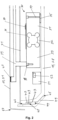
- Fig. 2 shows a section through the housing 18 of a sales device 10.
- the housing 18 is a cast metal housing and can take on complex shapes.
- a load cell 30 is screwed onto a base 35 with screws 34.
- the load cell 30 comprises a fixed section 31 screwed to the housing 18, a deformation section 32 and a movable section 33 on which a load cross 39 is attached with a fastening 38.
- the load cross 39 carries the load plate 11 of the sales device, with rubber buffers 40 being attached between the load cross 39 and the load plate 11.
- the load plate 11 comprises a bend 50 on its edges, so that the load plate 11 projects laterally downwards over the upper edges of the housing 18.
- the interior of the housing 18, in which the load cell 30 and also a control unit 51 and possibly other components of the sales device such as a power supply and the like are located, is covered with a cover 41.
- the housing 18 consists of a base plate and four upwardly projecting side walls.
- the housing is made of cast metal and is thus formed in one piece. The transition between the base plate and the side walls is bevelled.
- a recess 44 is provided in the upper area of the side walls so that a vertical outer wall 47 is set back slightly on the side walls of the housing 18.
- the carrier 42 of the light strip 19 is glued to this vertical outer wall 47.
- the carrier 42 is made of flexible material and can therefore also be guided around the corners of the housing 18 in the recess 44.
- flexible means that the carrier 42 can be bent at least perpendicular to the plane in which the carrier 42 runs, but not necessarily in the plane of the carrier 42 itself.
- LED lamps 43 are mounted on the carrier 42.
- the LED lamps 43 can be mounted in the longitudinal direction of the carrier 42 at a density of up to ten LED lamps 43 per cm.
- Carrier 42 and LED lamps 43 are covered on the side of the LED lamps with a protective layer 48 made of silicone or phosphor.
- the protective layer 48 is not only applied to the LED lamps 43 themselves before they are mounted on the carrier 42, but is also applied over the carrier 42 and the LED lamps 42 after the LED lamps 43 have been mounted on the carrier 42. In this way, a higher density of the LED lamps 43 on the carrier 42 can be achieved and the beam angle for homogeneous light of each LED lamp 43 increases to approximately 170°.
- a protective layer 48 made of silicone is applied when the LED lamps 43 emit light in the wavelength range from 450°nm to 500°nm, 500°nm to 570°nm or 610°nm to 760°nm and the different LED lamps 43 are arranged in regular arrangements on the carrier 42. This allows the light strip 19 to be made to glow in RGB colors via the control unit 51.
- a protective layer 48 made of phosphor is applied when the LED lamps 43 emit light in the wavelength range from 230 nm to 500 nm (ultraviolet to blue light). The protective layer 48 made of phosphor makes this light visible to the operator as white light.
- the recess 44 with carrier 42, LED lamps 43 and protective layer 48 is covered by a diffuser 49.
- the diffuser 49 provides mechanical protection for the light strip 19, 29 and simultaneously refracts the light so that the light strip 19 acts like a homogeneous light source.
- the diffuser 49 can be structured on its outer surface, i.e. surface-treated.
- the effect that the light strip 19 acts like a homogeneous light source is caused by the high density of LED lamps 43 and by the common protective layer 48 made of silicone or phosphor on the LED lamps 43 and is reinforced or completed by the diffuser 49 and the external structuring of the diffuser 49.
- the diffuser 49 rests on surfaces 45, 46 of the housing 18 above and below the recess 44 and is glued to these surfaces 45, 46, locked thereto with a locking connection or screwed thereto.
- the diffuser 49 is a ring-shaped component that is pushed over the housing 18 from below and fits positively onto the side walls of the housing 18.
- the diffuser 49 is made of translucent material, in particular of translucent polycarbonate.
- the control unit 51 comprises a state machine 52 which represents at least one release state of the vending device.
- the control unit controls the light strip 19 based on the state of the state machine 52.
- Fig. 3 shows a schematic of a method for operating a sales device.
- a customer who is a user of the sales device for self-checkout starts a sales process.
- he uses the product scanner to scan a product that he wants to buy with the sales device.
- the product scanner determines the article number of the product and sends this to the control device.
- a communication device of the sales device uses the article number of the product via a network to obtain an article weight associated with the product in step 32.
- the customer places the scanned product on the load plate and the weighing module determines the associated weight of the product in step 33.
- the article weight and the weighed weight of the product are compared. If the weights match, the control device moves the state machine to the release state in step 35.
- the light strip is controlled according to the release state, in particular in the case of a colored light strip, the light strip lights up green and in the case of a monochrome light strip, the light strip lights up permanently.
- the process continues to step 31, where the customer scans another item.
- the weighing module is tared.
- the control device puts the state machine into the blocking state in step 36.
- the light strip is controlled according to the blocking state, in particular in the case of a colored light strip the light strip lights up red and in the case of a monochrome light strip the light strip flashes.
- the customer is informed of the error via the operator display and asked to remove the article from the load plate.
- the weight is reduced via the weighing module so that the previous weight is detected on the weighing module, which corresponds to the tared weight and therefore 0 kg.
- the sales device has thus detected that the customer has removed the incorrectly placed product from the load plate.
- the process then proceeds to step 31, where the customer can scan a new product.
- step 35 If the process is in step 35 and the state machine is therefore in a release state, the customer can end the purchase via the operator display and start a payment process with the payment terminal. The customer completes the purchase process by paying.
- the customer can pay for several products in this way, which they scan and verify one after the other. Each product is verified individually using the process, so that tolerances do not accumulate during the weighing process. Since the weighing module is repeatedly tared when moving from step 35 to step 31, the customer can place all products one after the other on the load plate, additively, until all the products to be paid for are on the load plate. Nevertheless, the weighing module only ever weighs the newly placed product using the respective tare function and passes this weight on to the control unit for verification.
- DSP digital signal processor
- ASIC application specific integrated circuit
- FPGA field programmable gate array
- ROM read only memory
- RAM random access memory
Landscapes
- Physics & Mathematics (AREA)
- Business, Economics & Management (AREA)
- General Physics & Mathematics (AREA)
- Accounting & Taxation (AREA)
- Engineering & Computer Science (AREA)
- Theoretical Computer Science (AREA)
- Finance (AREA)
- Strategic Management (AREA)
- General Business, Economics & Management (AREA)
- Mathematical Physics (AREA)
- Control Of Vending Devices And Auxiliary Devices For Vending Devices (AREA)
- Cash Registers Or Receiving Machines (AREA)
Abstract
Description
- Die vorliegende Erfindung betrifft eine Verkaufsvorrichtung zum Selbst-Checkout mit einem Wägemodul, einem Produktscanner zum Scannen von Artikelnummern von Produkten und einer Kommunikationseinheit zum Senden und Empfangen von Artikeldaten an ein Netzwerk zum Speichern von Artikeldaten. Das Wägemodul umfasst ein Gehäuse, in dem eine Wägezelle untergebracht ist. Die Wägezelle umfasst einen festen Abschnitt, einen Verformungsabschnitt und einen beweglichen Abschnitt. Der feste Abschnitt ist mit dem Gehäuse verbunden und der bewegliche Abschnitt trägt ein Lastkreuz mit einer Lastplatte. Der Verformungsabschnitt weist einen Dehnungsmesstreifen zur Messung eines auf die Lastplatte wirkenden Gewichts auf.
- Derartige Verkaufsvorrichtungen zum Selbst-Checkout sind dem Fachmann gut bekannt. Diese Verkaufsvorrichtungen umfassen in aller Regel ein Bedienerdisplay zur Interaktion mit der Verkaufsvorrichtung, durch das der Bediener durch den Selbst-Checkoutvorgang geführt wird. Dabei ist es für den Bediener eine Herausforderung, Fehler zu erkennen, zum Beispiel wenn ein Produkt nicht gescannt wurde.
- Aufgabe der Erfindung ist es, eine einfache Vorrichtung zu schaffen, die dem Bediener den Selbst-Checkoutvorgang erleichtert und eine intuitive Interaktion mit der Verkaufsvorrichtung ermöglicht.
- Diese Aufgabe wird durch eine Verkaufsvorrichtung mit den Merkmalen des Anspruchs 1 gelöst.
- Erfindungsgemäß wird eine Verkaufsvorrichtung zum Selbst-Checkout mit einem Wägemodul, einem Produktscanner zum Scannen von Artikelnummern von Produkten und einer
- Kommunikationseinheit zum Senden und Empfangen von Artikeldaten an ein Netzwerk zum Speichern von Artikeldaten vorgeschlagen. Das Wägemodul umfasst ein Gehäuse, in dem eine Wägezelle untergebracht ist. Die Wägezelle umfasst einen festen Abschnitt, einen Verformungsabschnitt und einen beweglichen Abschnitt. Der feste Abschnitt ist mit dem Gehäuse verbunden. Der bewegliche Abschnitt trägt ein Lastkreuz mit einer Lastplatte. Der Verformungsabschnitt weist einen Dehnungsmesstreifen zur Messung eines auf die Lastplatte wirkenden Gewichts auf. An der Außenwand des Gehäuses ist ein Leuchtband im Wesentlichen umlaufend am Gehäuse angebracht. Im Wesentlichen umlaufend in diesem Zusammenhang meint, dass das Leuchtband drei Seiten und einen großen Teil der vierten Seite des Gehäuses umläuft, jedoch dass der Anfang und das Ende des Leuchtbandes nicht verbunden oder zusammentreffen müssen. Ein Abstand zwischen Anfang und Ende des Leuchtbandes, auf der Seite, auf der sich Anfang und Ende begegnen, ist damit ebenfalls gemeint. Die Verkaufsvorrichtung umfasst eine Steuereinheit, die eine Artikelnummer vom Produktscanner empfängt und über die Kommunikationseinheit Artikeldaten zu dieser Artikelnummer aus dem Netzwerk empfängt. Die Artikeldaten umfassen mindestens ein Artikelgewicht. Die Steuereinheit umfasst eine Zustandsmaschine, die mindestens einen Self-Checkout-Zustand der Verkaufsvorrichtung abbildet, wobei die Steuereinheit das Leuchtband aufgrund des Zustands der Zustandsmaschine ansteuert.
- In einer Ausführungsform befindet sich die Zustandsmaschine in einem Freigabezustand, wenn das Artikelgewicht und das gemessene Gewicht übereinstimmen. Die Zustandsmaschine befindet sich in einem Sperrzustand, wenn das Artikelgewicht und das gemessene Gewicht nicht übereinstimmen.
- In einer ersten Ausführungsform beaufschlagt die Steuereinheit das Leuchtband gepulst mit einer Spannung, wenn die Zustandsmaschine in einem Sperrzustand ist. Das heißt, die Spannung wird regelmäßig angeschaltet und ausgeschaltet. Dadurch entsteht ein Blinken des Leuchtbandes. Dabei ist die Frequenz und die Länge der Spannungspulse so zu wählen, dass das menschliche Auge das Leuchtband als blinkend wahrnimmt. Wenn die Zustandsmaschine in einem Freigabezustand ist, beaufschlagt die Steuereinheit das Leuchtband permanent mit einer Spannung. Das heißt, das Leuchtband leuchtet dauerhaft. Der Fachmann versteht, dass es Ausführungsformen gibt, bei denen die gepulste Spannung für den Freigabezustand herangezogen wird und die permanente Spannung für den Sperrzustand.
- In einer Ausführungsform umfasst das Leuchtband erste, zweite und dritte LED-Leuchtmittel. Die ersten LED-Leuchtmittel erzeugen Licht in einem Wellenlängenbereich von 450°nm bis 500°nm, was der Farbe Blau entspricht. Die zweiten LED-Leuchtmittel erzeugen Licht in einem Wellenlängenbereich von 500°nm bis 570°nm, was der Farbe Grün entspricht. Die dritten LED-Leuchtmittel erzeugen Licht in einem Wellenlängenbereich 610°nm bis 760°nm, was der Farbe Rot entspricht. In einer Ausführungsform besteht das Leuchtband aus einem flexiblen Träger. Auf dem flexiblen Träger sind die LED-Leuchtmittel angeordnet. In einer Ausführungsform umfasst der Träger eine bis zehn LED-Leuchtmittel pro cm Länge. Die ersten, zweiten und dritten LED-Leuchtmittel sind in regelmäßigen Anordnungen auf dem Träger angeordnet. Die ersten LED-Leuchtmittel bilden eine erste Gruppe von LED-Leuchtmitteln. Die zweiten LED-Leuchtmittel bilden eine zweite Gruppe von LED-Leuchtmitteln. Die dritten LED-Leuchtmittel bilden eine dritte Gruppe von LED-Leuchtmitteln. Die LED-Leuchtmittel einer Gruppe werden durch die Steuereinheit jeweils gemeinsam angesteuert. In einer Ausführungsform ist das Leuchtband auf der Seite, auf der die LED-Leuchtmittel angebracht sind, mit Silikon überzogen. Silikon ist lichtdurchlässig. Gleichzeitig entsteht ein diffuser Effekt, so dass das Licht der einzelnen LED-Leuchtmittel etwas gestreut wird. So entstehen aus den drei Gruppen von LED-Leuchtmitteln, die für das menschliche Auge als blau, grün und rot wahrnehmbar sind, überlagerte Farben, so dass annähernd der gesamte RGB-Farbraum zur Verfügung steht.
- Somit nimmt das menschliche Auge das Leuchtband als rot leuchtend wahr, wenn sich die Zustandsmaschine in einem ersten Zustand befindet und die dritte Gruppe von LED-Leuchtmitteln durch die Steuereinrichtung mit Spannung beaufschlagt wird. Das menschliche Auge nimmt das Leuchtband als grün leuchten wahr, wenn sich die Zustandsmaschine im zweiten Zustand befindet und die zweite Gruppe von LED-Leuchtmitteln durch die Steuereinrichtung mit Spannung beaufschlagt wird.
- In einer Ausführungsform beaufschlagt die Steuereinheit die zweite Gruppe von LED-Leuchtmitteln des Leuchtbandes permanent mit einer Spannung, wenn sich die Zustandsmaschine in einem Freigabezustand befindet. Dies entspricht einem Leuchten in der Farbe grün. Die Steuereinheit beaufschlagt die dritte Gruppe von LED-Leuchtmitteln des Leuchtbandes permanent mit einer Spannung, wenn sich die Zustandsmaschine in einem Sperrzustand befindet. Dies entspricht einem Leuchten in der Farbe rot.
- In einer Ausführungsform ist das Gehäuse einstückig und wannenförmig ausgebildet. Der Fachmann versteht unter einem einstückig und wannenförmig ausgebildeten Gehäuse eine Form eines Gehäuses, die einer Wanne ähnelt. Sie hat eine quadratische oder rechteckige Grundfläche, wobei die Ecken abgerundet sein können. Das Gehäuse hat einen Grundkörper, der in einer Ausführungsform aus einem Metallguss hergestellt ist und somit auch komplexe Formen, insbesondere Öffnungen und innere Wandungen aufweisen kann. Die Länge und die Breite des Gehäuses sind wesentlich größer als dessen Höhe. Das Gehäuse umfasst eine Bodenplatte mit seitlichen Wänden, die einstückig an der Bodenplatte ausgebildet sind. Das Gehäuse ist oben offen und mit einem Freiraum im Inneren, um unterschiedliche Module, wie die Wägezelle, elektronische Module und Anderes im Inneren des Gehäuses aufzunehmen. In einer Ausführungsform ist der Innenbereich des Gehäuses oben mit einer Abdeckung abgedeckt. Unter den Begriff einstückig und wannenförmig fällt auch ein Gehäuse, das im Inneren Trennwände für verschiedene Räume oder Stabilisierungsstreben hat. Des Weiteren fällt auch ein Gehäuse darunter, dessen Bodenplatte an einigen Stellen stufenförmig ausgebildet ist, so dass an diesen Stellen des Gehäuses unterhalb der Bodenplatte des Gehäuses ein Freiraum entsteht, wenn der Grundkörper auf einer ebenen Fläche abgesetzt wird. Dieser Freiraum dient zum Beispiel für das Anbringen von Steckern unterhalb des Gehäuses. Das Gehäuse ist auch dann als einstückig und wannenförmig zu verstehen, wenn an verschiedenen Stellen in der, insbesondere abgestuften, Bodenplatte oder seitlichen Wänden Durchgangsöffnungen vorhanden sind, zum Beispiel für das Anbringen von Steckerbuchsen, das Durchführen von Kabeln oder die Montage von Trägern und anderen Elementen der Verkaufsvorrichtung. Der Begriff wannenförmig ist deswegen nur als beschreibend für das grundsätzliche Erscheinungsbild des Gehäuses anzusehen.
- In einer Ausführungsform handelt es sich bei der Zustandsmaschine um einen endlichen Automaten, der aus Zuständen, Zustandsübergängen und Aktionen besteht.
- In einer Ausführungsform tariert die Steuereinheit nach einem Verifikationsvorgang das Wägemodul. Das heißt, wird ein Produkt durch den Bediener eingescannt und zur Verifikation auf das Wägemodul gelegt und wird eine Übereinstimmung zwischen Gewicht des gewogenen Produkts und Artikelgewicht festgestellt, so ist der Scannvorgang des Produktscanners verifiziert. Dann wird das Wägemodul tariert, das heißt, die Waage wird auf Null gesetzt, obwohl der Artikel noch auf der Lastplatte liegt. Wird dann ein weiterer Artikel zusätzlich auf die Lastplatte gelegt, so sendet das Wägemodul nur den Gewichtswert des weiteren Artikels an die Steuereinheit. Auf diese Weise wird immer nur der Gewichtswert des neuen, zusätzlich auf die Lastplatte aufgelegten Artikels an die Steuereinheit gesendet.
- In einer Ausführungsform versetzt die Steuereinheit beim Detektieren einer Last durch das Wägemodul ohne eine Artikelnummer vom Produktscanner zu erhalten, die Zustandsmaschine in den Sperrzustand und/oder zeigt auf einem Bedienerdisplay ein Hinweissignal an, dass der Scanvorgang wiederholt werden muss. Sollte ein Bediener vergessen einen Artikel zu scannen und legt ihn ungescannt auf das Wägemodul, so wird mit dem Leuchtband ein Sperrzustand angezeigt und der Bediener wird auf seinen Fehler aufmerksam gemacht. Ergänzend wird in einer Ausführungsform der Bediener über das Bedienerdisplay auf seinen Fehler hingewiesen.
- In einer Ausführungsform umfasst die Verkaufsvorrichtung ein Bezahlterminal. Der Bezahlvorgang kann nur dann durch eine Nutzereingabe gestartet werden, wenn die Zustandsmaschine sich im Freigabezustand befindet. In einer Ausführungsform versetzt die Steuereinheit die Zustandsmaschine nach erfolgreichem Abschluss des Bezahlvorgangs in einen Abschlusszustand. Dieser Abschlusszustand bedeutet das erfolgreiche Beenden des Selbst-Checkoutvorgangs.
- In einer Ausführungsform umläuft das Leuchtband das Gehäuse einmal, insbesondere umläuft das Leuchtband das Gehäuse im oberen Bereich seiner Seitenwände einmal, wobei zwischen Anfang und Ende des Leuchtbandes ein, im Verhältnis zur Länge des Leuchtbandes, kleiner Abstand sein kann. Dabei umfasst die Verkaufsvorrichtung eine Lastplatte, die auf dem Lastkreuz abgelegt ist. Dabei führen die äußeren Ränder der Lastplatte über das Lastkreuz und über die Oberkante des Gehäuses nach unten, so dass die Lastplatte wie ein Deckel auf der Oberseite des Gehäuses schwebt. In einer Ausführungsform befindet sich das Leuchtband im oberen Bereich der Seitenwände des Gehäuses, jedoch unterhalb der Ränder der Lastplatte. In einer Ausführungsform ist das Leuchtband am oberen Rand des Gehäuses derart angebracht, dass es von den überstehenden Rändern der Lastplatte verdeckt wird. In diesem Fall leuchtet das Licht des Leuchtbandes diffus unter den nach unten stehenden Rändern der Lastplatte hervor.
- In einer Ausführungsform sind in dem flexiblen Trägermaterial des Leuchtbandes elektrische Leitungen für die Ansteuerung der LED-Leuchtmittel integriert.
- In einer Ausführungsform erzeugen die LED-Leuchtmittel Licht im Wellenlängenbereich von 230 nm bis 500 nm. Der Träger mit den LED-Leuchtmitteln ist mit Phosphor überzogen. Insbesondere ist das Leuchtband auf der Seite, auf der die LED-Leuchtmittel angebracht sind, mit Phosphor überzogen. Phosphor wandelt das blaue oder ultraviolette Licht der LED-Leuchtmittel in weißes Licht.
- Es ist insbesondere zu beachten, dass nicht jedes der LED-Leuchtmittel einzeln und separat mit Phosphor überzogen ist bzw. wurde, sondern dass die LED-Leuchtmittel zuerst auf dem Träger montiert werden und dann die ganze Seite des Trägers mit Phosphor überzogen wird. So kann die Dichte der LED-Leuchtmittel pro Länge des Leuchtbandes deutlich erhöht werden und es kommt zu einem sehr homogenen Leuchteffekt. Dies führt auch dazu, dass die Ausleuchtung durch das Licht der LED-Leuchtmittel im Bezug zur Ebene des Leuchtbandes ca. 170° beträgt, das heißt, das Licht ist auch aus sehr spitzen Winkeln wahrnehmbar.
- In einer Ausführungsform weist der flexible Träger auf der den LED-Leuchtmitteln gegenüberliegenden Seite eine Schicht aus Klebematerial auf. In einer Ausführungsform handelt es sich um eine Schicht aus wärmeleitendem Klebematerial. Das Leuchtband ist mit dem Klebematerial am Gehäuse angebracht, insbesondere angeklebt. Die durch die LED-Leuchtmittel entstehende Hitze wird über die Schicht aus Klebematerial, insbesondere über das wärmeleitende Klebematerial, an das Gehäuse abgegeben.
- Das Klebematerial haftet dabei auf einer Fläche aus unbeschichtetem und/oder beschichtetem Metallguss, sodass das Gehäuse an der Stelle, an der das Leuchtband angeklebt wird, beschichtet oder unbeschichtet sein kann.
- In einer Ausführungsform ist das Leuchtband mit der Steuereinheit elektrisch verbunden. Das Leuchtband wird von der Steuereinheit mit einer Gleichspannung im Bereich von 6°Volt bis 36°Volt, insbesondere 12°Volt oder 24°Volt, angesteuert.
- In einer Ausführungsform umfasst das Gehäuse eine Aussparung oder eine einseitige Aussparung, die im oberen Gehäusebereich an der Außenseite des Gehäuses umlaufend angebracht ist, in die das Leuchtband eingeklebt ist. Unter Aussparung ist dabei eine Vertiefung in der Gehäusewand zu verstehen in der Form einer Rille. Eine einseitige Aussparung meint eine Kante, die zum Beispiel in einer schräg verlaufenden Gehäusewand vorhanden ist. Die Kante bildet eine Vertiefung, deren hinteres Ende zur Aufnahme des Leuchtbandes eine vertikale Ebene ist.
- In einer Ausführungsform umfasst die Verkaufsvorrichtung einen Diffusor, der außen am Gehäuse angebracht ist und die Aussparung abdeckt. Der Diffusor sorgt für eine Streuung des Lichtes der LED-Leuchtmitte, sodass nicht mehr zu erkennen ist, dass es sich um diskrete Lichtquellen handelt, sondern dass der Eindruck entsteht, es würde sich um eine ausgedehnte homogene Lichtmittel handeln. Außerdem sorgt der Diffusor dafür, dass das Leuchtband aus jedem Betrachtungswinkel gleich hell wirkt. Der Diffusor verstärkt den Effekt des Phosphors beziehungsweise des Silikons.
- In einer Ausführungsform besteht der Diffusor aus einem transluzenten Material. In einer Ausführungsform handelt es sich bei dem transluzenten Material um ein transluzentes Polycarbonat.
- In einer Ausführungsform umfasst der Diffusor auf seiner Außenseite eine Strukturierung. Die Strukturierung macht den Diffusor von der Außenseite in Richtung Gehäuse blickdicht. Hingegen ist der Diffusor von der Gehäuseseite nach außen transluzent.
- In einer Ausführungsform ist der Diffusor als Ring ausgebildet. Der Ring hat die Abmessungen des Gehäuses im Bereich der Aussparung. Der Ring ist formschlüssig an dem Gehäuse über der Aussparung angebracht. Insbesondere ist der Ring mit einem Rastmechanismus angebracht. In einer Ausführungsform deckt der Diffusor die Aussparung ab. In einer Ausführungsform ist der Diffusor mit dem Gehäuse verklebt oder verschraubt.
- In einer Ausführungsform ist die Distanz zwischen den LED-Leuchtmitteln und der Innenseite des Diffusors kleiner 3°mm. In einer Ausführungsform ist die Distanz zwischen den LED-Leuchtmitteln und der Innenseite des Diffusors kleiner 1°mm.
- In einer Ausführungsform ist das Leuchtband eine Seitenlichtfaser. In einer Ausführungsform besteht die Seitenlichtfaser aus vier insbesondere polyoptischen Einzelfasern, die von einem diffusen, weissen Mantel umhüllt werden. In einer Ausführungsform sind die Oberflächen der vier polyoptischen Einzelfasern durch ein abrasives Verfahren aktiviert, sodass ein homogener Lichtaustritt im Abstrahlwinkel von 360° aus der Seitenlichtfaser entsteht. Seitenlichtfasern sind zum Beispiel in der
EP3525017B1 und derEP3524877B1 offenbart. - In einer Ausführungsform berücksichtig die Steuereinheit, im Fall, dass die Artikelnummer einem Artikel entspricht, der der Fertigverpackungsverordnung unterliegt, die in der Fertigverpackungsverordnung vorgegeben Toleranzen. Das heißt, anhand der Artikelnummer wird kein konkretes Gewicht zur Verifikation des Artikels vorgegeben, sondern ein Gewichtsband, das der Fertigverpackungsverordnung entspricht. Die Zustandsmaschine befindet sich im Freigabezustand oder wird in den Freigabezustand versetzt, wenn das Artikelgewicht sich innerhalb des in der Fertigverpackungsverordnung vorgegeben Gewichtsbandes befindet.
- Im Rahmen dieser Offenbarung sind identische Gewichte zwischen Artikelgewicht anhand der Artikelnummer und durch das Wägemodul bestimmtes Gewicht auch als identisch anzusehen, wenn sie bis auf eine Toleranz identisch sind.
- Die Kommunikationseinheit zum Senden und Empfangen von Artikeldaten aus einem Netzwerk kann sowohl als drahtgebundene wie auch drahtlose Kommunikationseinheit realisiert sein. In einer Ausführungsform ist das Netzwerk ein Cloud-Netzwerk.
- Einige Ausführungsformen der Erfindung sind in den Zeichnungen beispielhaft gezeigt und nachfolgend beschrieben. Es zeigen, jeweils in schematischer Darstellung:
- Fig. 1
- Eine erfindungsgemäße Verkaufsvorrichtung,
- Fig. 2
- Einen Ausschnitt einer erfindungsgemäßen Verkaufsvorrichtung, und
- Fig. 3
- Ein erfindungsgemäßes Verfahren zum Betrieb einer Verkaufsvorrichtung.
-
Fig. 1 zeigt eine erfindungsgemäße Verkaufsvorrichtung 10 nach einer ersten Ausführungsform. Die Verkaufsvorrichtung umfasst einen Wägemodul mit einem Gehäuse 18, in dem eine Wägezelle untergerbacht ist. Die Wägezelle trägt ein Lastkreuz, das seinerseits eine Lastplatte 11 trägt. Die Lastplatte 11 hat einen nach unten stehenden Rand, der über die obere Kante des Gehäuses 18 ragt. Am Wägemodul ist ein Stativ 15 befestigt, das einen Drucker 12 mit einer Etikettenausgabe 16 trägt. Das Stativ 15 trägt ferner ein Bedienerdisplay 13, das als Touchscreen ausgebildet ist. Das Wägemodul ruht auf vier in seinen Ecken angebrachten Füßen 17. An äußeren Rand des Gehäuses 18 ist umlaufend ein Leuchtband 19 angebracht, das von einer Steuereinheit in Abhängigkeit eines Freigabezustandes der Verkaufsvorrichtung angesteuert wird. Mit der Verkaufsvorrichtung 10 verbunden oder in die Verkaufsvorrichtung 10 integriert ist ein Bezahlterminal 102 zum Abwickeln eines elektronischen Bezahlvorgangs. Des Weiteren ist mit der Verkaufsvorrichtung 10 verbunden oder in die Verkaufsvorrichtung 10 integriert ein Produktscanner 101 zum Scannen einer Artikelnummer in Form eines Barcodes 104 oder QR-Codes. Der Barcode 104 oder QR-Code gibt eine eindeutige Artikelnummer wieder, anhand dessen der Artikel zu identifizieren ist. Die Verkaufsvorrichtung umfasst eine Kommunikationseinheit, mit der durch Senden einer entsprechenden Artikelnummer an ein Netzwerk zum Artikel gehörende Artikeldaten, wie zum Beispiel das Gewicht, empfangen werden können. Unter dem Gewicht des Artikels ist im Rahmen dieser Offenbarung das Gewicht des zugehörigen Produkts inklusive der Produktverpackung zu verstehen. Beispielhaft sind auf der Lastplatte 11 der Verkaufsvorrichtung zwei Produkte 105, 106 gezeigt, während ein weiteres Produkt 103 am Produktscanner 101 gezeigt ist. -
Fig. 2 zeigt einen Schnitt durch das Gehäuse 18 einer Verkaufsvorrichtung 10. Das Gehäuse 18 ist ein Metallgussgehäuse und kann komplexe Formen annehmen. Im Inneren des Gehäuses 18 ist auf einem Sockel 35 eine Wägezelle 30 mit Schrauben 34 verschraubt. Die Wägezelle 30 umfasst einen mit dem Gehäuse 18 verschraubten festen Abschnitt 31, einen Verformungsabschnitt 32 und einen beweglichen Abschnitt 33, auf dem ein Lastkreuz 39 mit einer Befestigung 38 angebracht ist. Das Lastkreuz 39 trägt die Lastplatte 11 der Verkaufsvorrichtung, wobei zwischen Lastkreuz 39 und Lastplatte 11 Gummipuffer 40 angebracht sind. Die Lastplatte 11 umfasst an ihren Rändern eine Biegung 50, so dass die Lastplatte 11 seitlich nach unten über die oberen Ränder des Gehäuses 18 ragt. Die Gewichtskraft eines Produkts auf der Lastplatte 11 und auch die Gewichtskraft von Lastkreuz 39 und Lastplatte 11 selbst wirken so auf den beweglichen Abschnitt 33 der Wägezelle 30. Dies führt zu einer mechanischen Verformung des Verformungsabschnitts 32, welche über auf dem Verformungsabschnitt 32 angebrachte Dehnungsmesstreifen 36 gemessen wird. Die gemessene Verformung wird mit einer Auswerteeinheit 37 bestimmt und in einen Gewichtswert des Produkts umgerechnet. Der Innenraum des Gehäuses 18, in dem sich die Wägezelle 30 und auch eine Steuereinheit 51 und ggf. weitere Komponenten der Verkaufsvorrichtung wie Netzteil und ähnliches befinden, ist mit einer Abdeckung 41 abgedeckt. - Das Gehäuse 18 besteht aus einer Bodenplatte und vier nach oben ragenden Seitenwänden. Das Gehäuse ist aus Metallguss und somit einstückig ausgebildet. Der Übergang zwischen Bodenplatte und Seitenwänden ist angeschrägt. Im oberen Bereich der Seitenwände ist eine Aussparung 44 angebracht, so dass eine vertikal stehende Außenwand 47 an den Seitenwänden des Gehäuses 18 etwas zurückversetzt ist. An dieser vertikal stehenden Außenwand 47 ist der Träger 42 des Leuchtbandes 19 festgeklebt. Der Träger 42 ist aus flexiblem Material gebildet und kann somit auch um die Ecken des Gehäuses 18 in der Aussparung 44 geführt werden. Flexibel meint in diesem Zusammenhang, dass der Träger 42 zumindest senkrecht zur Ebene, in der der Träger 42 verläuft, verbogen werden kann, nicht gezwungenermaßen auch in der Ebene des Trägers 42 selbst. Auf dem Träger 42 sind LED-Leuchtmittel 43 abgebracht. Die LED-Leuchtmittel 43 können in Längsrichtung des Trägers 42 mit einer Dichte von bis zu zehn LED-Leuchtmittel 43 pro cm angebracht sein. Träger 42 und LED-Leuchtmittel 43 sind auf der Seite der LED-Leuchtmittel mit einer Schutzschicht 48 aus Silikon oder Phosphor abgedeckt. Dabei ist die Schutzschicht 48 nicht nur auf den LED-Leuchtmitteln 43 selbst vor deren Montage auf dem Träger 42 angebracht, sondern wird nach der Montage der LED-Leuchtmittel 43 auf dem Träger 42 über den Trägers 42 und die LED-Leuchtmittel 42 angebracht. So kann eine höhere Dichte der LED-Leuchtmittel 43 auf dem Träger 42 erreicht werden und der Abstrahlwinkel für homogenes Licht jedes LED-Leuchtmittels 43 erhöht sich auf ca. 170°. Eine Schutzschicht 48 aus Silikon wird aufgetragen, wenn die LED-Leuchtmittel 43 Licht im Wellenlängenbereich von 450°nm bis 500°nm, 500°nm bis 570°nm beziehungsweise 610°nm bis 760°nm erzeugen und die unterschiedlichen LED-Leuchtmittel 43 in regelmäßigen Anordnungen auf dem Träger 42 angeordnet sind. Hierdurch kann das Leuchtband 19 in RGB Farben über die Steuereinheit 51 zum Leuchten gebracht werden. Eine Schutzschicht 48 aus Phosphor wird aufgetragen, wenn die LED-Leuchtmittel 43 Licht im Wellenlängenbereich von 230 nm bis 500 nm (ultraviolettes bis blaues Licht) abgeben. Durch die Schutzschicht 48 aus Phosphor wird dieses Licht für den Bediener als weißes Licht sichtbar.
- Die Aussparung 44 mit Träger 42, LED-Leuchtmitteln 43 und Schutzschicht 48 ist durch einen Diffusor 49 abgedeckt. Der Diffusor 49 bietet einen mechanischen Schutz des Leuchtbandes 19, 29 und bricht das Licht gleichzeitig, so dass das Leuchtband 19 wie eine homogene Lichtquelle wirkt. Dazu kann der Diffusor 49 auf seiner äußeren Fläche strukturiert, das heißt oberflächenbearbeitet sein. Der Effekt, dass das Leuchtband 19 wie eine homogene Lichtquelle wirkt, wird durch die hohe Dichte an LED-Leuchtmitteln 43 und durch die gemeinsame Schutzschicht 48 aus Silikon oder Phosphor auf den LED-Leuchtmitteln 43 hervorgerufen und durch den Diffusor 49 und die außenseitige Strukturierung des Diffusors 49 verstärkt bzw. vervollständigt. Der Diffusor 49 liegt an Flächen 45, 46 des Gehäuses 18 oberhalb und unterhalb der Aussparung 44 an und ist an diese Flächen 45, 46 geklebt, mit einer Rastverbindung daran verrastet oder verschraubt. Der Diffusor 49 ist ein ringförmiges Bauteil, das von unten über das Gehäuse 18 geschoben wird und formschlüssig auf die Seitenwände des Gehäuses 18 passt. Der Diffusor 49 ist aus transluzentem Material, insbesondere aus transluzentem Polycarbonat, hergestellt.
- Die Steuereinheit 51 umfasst eine Zustandsmaschine 52, die mindestens einen Freigabezustand der Verkaufsvorrichtung abbildet. Die Steuereinheit steuert das Leuchtband 19 aufgrund des Zustandes der Zustandsmaschine 52.
-
Fig. 3 zeigt schematische ein Verfahren zum Betrieb einer Verkaufsvorrichtung. In Schritt 30 startet ein Kunde, der ein Nutzer der Verkaufsvorrichtung zum Selbst-Checkout ist, einen Verkaufsvorgang. In Schritt 31 scannt er mit dem Produktscanner ein Produkt, das er mit der Verkaufsvorrichtung kaufen möchte. Der Produktscanner bestimmt die Artikelnummer des Produkts und sendet diese an die Steuervorrichtung. Eine Kommunikationsvorrichtung der Verkaufsvorrichtung bezieht aufgrund der Artikelnummer des Produkts über ein Netzwerk ein zum Produkt zugehöriges Artikelgewicht in Schritt 32. Der Kunde legt dann das gescannte Produkt auf die Lastplatte und das Wägemodul bestimmt das zugehörige Gewicht des Produkts in Schritt 33. In Schritt 34 wird das Artikelgewicht und das gewogene Gewicht des Produkts verglichen. Stimmt das Gewicht überein, so verbringt die Steuervorrichtung die Zustandsmaschine in den Freigabezustand in Schritt 35. Dabei wird das Leuchtband gemäß des Freigabezustands angesteuert, insbesondere im Falle eines farbigen Leuchtbandes leuchtet das Leuchtband grün und im Falle eines monochromen Leuchtband leuchtet das Leuchtband permanent. Das Verfahren geht weiter zu Schritt 31, in dem der Kunde einen weiteren Artikel scannt. Das Wägemodul wird hierbei tariert. - Stimmt das Gewicht nicht überein, so verbringt die Steuervorrichtung die Zustandsmaschine in den Sperrzustand in Schritt 36. Dabei wird das Leuchtband gemäß des Sperrzustands angesteuert, insbesondere im Falle eines farbigen Leuchtbandes leuchtet das Leuchtband rot und im Falle eines monochromen Leuchtband blinkt das Leuchtband. Der Kunde wird über das Bedienerdisplay auf den Fehler hingewiesen und zur Entnahme des Artikels von der Lastplatte aufgefordert. In Schritt 37 wird über das Wägemodul eine Reduktion des Gewichts, so dass auf dem Wägemodul das vorherige Gewicht wahrgenommen, das dem tarierten Gewicht und somit 0 kg entspricht. Damit hat die Verkaufsvorrichtung detektiert, dass der Kunde das falsch aufgelegte Produkt wieder von der Lastplatte entnommen hat. Somit geht das Verfahren in Schritt 31 über, in dem der Kunde ein neues Produkt scannen kann.
- Befindet sich das Verfahren in Schritt 35 und befindet sich somit die Zustandsmaschine in einem Freigabezustand, kann der Kunde über das Bedienerdisplay den Einkauf beenden und einen Bezahlvorgang mit dem Bezahlterminal starten. Mit der Bezahlung schliesst der Kunde seinen Einkaufsvorgang ab.
- Es ist anzumerken, dass der Kunde auf diese Art mehrere Produkte bezahlen kann, die er nacheinander scannt und verifiziert. Jedes Produkt wird mit dem Verfahren einzeln verifiziert, so dass sich Toleranzen beim Wägevorgang nicht aufsummieren. Da beim Übergang von Schritt 35 auf Schritt 31 das Wägemodul immer wieder tariert wird, kann der Kunde alle Produkte nacheinander, additiv auf die Lastplatte legen, bis alle zu bezahlenden Produkte auf der Lastplatte liegen. Trotzdem wiegt das Wägemodul durch die jeweilige Tarafunktion immer nur das neu aufgelegte Produkt und gibt dieses Gewicht an die Steuereinheit zur Verifikation.
- Die Funktionen verschiedener in den Zeichnungen gezeigter Elemente, inklusive der Funktionsblöcke, können durch dezidierte Hardware oder durch generische Hardware, die in der Lage ist, Software auszuführen, im Zusammenhang mit der entsprechenden Software, realisiert werden. Falls die Funktionen mittels eines Prozessors zur Verfügung gestellt werden, können sie durch einen einzigen dezidierten Prozessor, einen einzigen geteilten Prozessor oder mehrere generische Prozessoren, die wiederum geteilt sein können, zur Verfügung gestellt werden. Die Funktionen können, ohne Einschränkung, durch einen digital signal processor (DSP), Netzwerk Prozessor, application specific integrated circuit (ASIC), field programmable gate array (FPGA), read only memory (ROM) mit gespeicherter Software, random access memory (RAM), und nichtflüchtige Speicher zur Verfügung gestellt werden.
Claims (15)
- Verkaufsvorrichtung zum Selbst-Checkout mit einem Wägemodul, einem Produktscanner zum Scannen von Artikelnummern von Produkten und einer Kommunikationseinheit zum Senden und Empfangen von Artikeldaten an ein Netzwerk zum Speichern von Artikeldaten, wobei das Wägemodul ein Gehäuse (18, 28) umfasst, in dem eine Wägezelle (30) untergebracht ist, wobei die Wägezelle (30) einen festen Abschnitt (31), einen Verformungsabschnitt (32) und einen beweglichen Abschnitt (33) umfasst, wobei der feste Abschnitt (31) mit dem Gehäuse (18, 28) verbunden ist und der bewegliche Abschnitt (33) ein Lastkreuz (39) mit einer Lastplatte (11, 21) trägt, wobei der Verformungsabschnitt (32) einen Dehnungsmesstreifen (36) zur Messung eines auf die Lastplatte (11, 21) wirkenden Gewichts aufweist, dadurch gekennzeichnet, dass an der Außenwand (47) des Gehäuses ein Leuchtband (19, 29) angebracht ist, das im Wesentlichen umlaufend am Gehäuse (18, 28) angebracht ist, und dass die Verkaufsvorrichtung eine Steuereinheit (51) umfasst, die eine Artikelnummer vom Produktscanner empfängt und über die Kommunikationseinheit Artikeldaten zu dieser Artikelnummer aus dem Netzwerk empfängt, wobei die Artikeldaten mindestens ein Artikelgewicht umfassen, wobei die Steuereinheit (51) eine Zustandsmaschine (52) umfasst, die mindestens einen Self-Checkout-Zustand der Verkaufsvorrichtung abbildet, wobei die Steuereinheit (51) das Leuchtband (19, 29) aufgrund des Zustands der Zustandsmaschine (52) ansteuert.
- Verkaufsvorrichtung zum Selbst-Checkout, nach Anspruch 1, dadurch gekennzeichnet, dass die Zustandsmaschine (52) sich in einem Freigabezustand befindet, wenn das Artikelgewicht und das gemessene Gewicht übereinstimmen, und dass die Zustandsmaschine sich in einem Sperrzustand befindet, wenn das Artikelgewicht und das gemessene Gewicht nicht übereinstimmen.
- Verkaufsvorrichtung zum Selbst-Checkout, nach Anspruch 2, dadurch gekennzeichnet, dass die Steuereinheit das Leuchtband gepulst mit einer Spannung beaufschlagt, wenn sich die Zustandsmaschine in einem Sperrzustand befindet und permanent mit einer Spannung beaufschlagt, wenn sich die Zustandsmaschine in einem Freigabezustand befindet.
- Verkaufsvorrichtung zum Selbst-Checkout, nach einem der Ansprüche 1 bis 3, dadurch gekennzeichnet, dass das Leuchtband eine erste Gruppe, eine zweite Gruppe und eine dritte Gruppe von LED-Leuchtmitteln umfasst und die Steuereinheit (51) die zweite Gruppe von LED-Leuchtmitteln (43) des Leuchtbandes (19, 29) permanent mit einer Spannung beaufschlagt, wenn sich die Zustandsmaschine (52) in einem Freigabezustand befindet und die dritte Gruppe von LED-Leuchtmitteln (43) des Leuchtbandes (19, 29) permanent mit einer Spannung beaufschlagt, wenn sich die Zustandsmaschine (52) in einem Sperrzustand befindet.
- Verkaufsvorrichtung zum Selbst-Checkout, nach einem der Ansprüche 1 bis 4, dadurch gekennzeichnet, dass die Steuereinheit nach einem Verifikationsvorgang durch die Zustandsmaschine das Wägemodul tariert.
- Verkaufsvorrichtung zum Selbst-Checkout, nach einem der Ansprüche 1 bis 5, dadurch gekennzeichnet, dass die Steuereinheit beim Detektieren einer Last durch das Wägemodul ohne eine Artikelnummer vom Produktscanner zu erhalten, die Zustandsmaschine in den Sperrzustand versetzt und/oder auf einem Bedienerdisplay ein Hinweissignal anzeigt, dass der Scanvorgang wiederholt werden muss.
- Verkaufsvorrichtung zum Selbst-Checkout, nach einem der Ansprüche 1 bis 6, dadurch gekennzeichnet, dass die Verkaufsvorrichtung ein Bezahlterminal umfasst und der Bezahlvorgang nur dann durch eine Nutzereingabe gestartet werden kann, wenn die Zustandsmaschine sich im Freigabezustand befindet, und insbesondere, dass die Steuereinheit die Zustandsmaschine nach erfolgreichem Abschluss des Bezahlvorgangs in einen Abschlusszustand versetzt.
- Verkaufsvorrichtung zum Selbst-Checkout, nach einem der Ansprüche 1 bis 7, dadurch gekennzeichnet, dass das Leuchtband aus einem flexiblen Träger (42) besteht, auf dem die LED-Leuchtmittel (43) angeordnet sind, wobei der Träger (42) insbesondere eine bis zehn LED-Leuchtmittel (43) pro cm Länge umfasst, und insbesondere in dem flexiblen Träger (42) des Leuchtbandes (19, 29) elektrische Leitungen für die Ansteuerung der LED-Leuchtmittel (43) integriert sind.
- Verkaufsvorrichtung zum Selbst-Checkout, nach einem der vorhergehenden Ansprüche, dadurch gekennzeichnet, dass die LED-Leuchtmittel (43) Licht im Wellenlängenbereich von 230 nm bis 500 nm erzeugen und insbesondere mit Phosphor überzogen sind, wobei insbesondere das Leuchtband (19, 29) auf der Seite, auf der die LED-Leuchtmittel (43) angebracht sind, mit Phosphor überzogen ist.
- Verkaufsvorrichtung zum Selbst-Checkout, nach einem der Ansprüche 1 bis 9, dadurch gekennzeichnet, dass der flexible Träger (42) erste, zweite und dritte LED-Leuchtmittel (43) umfasst, die Licht im Wellenlängenbereich von 450°nm bis 500°nm, 500°nm bis 570°nm beziehungsweise 610°nm bis 760°nm erzeugen und die ersten, zweiten und dritten LED-Leuchtmittel (43) in regelmäßigen Anordnungen auf dem Träger angeordnet sind, wobei die ersten, zweiten und dritten LED-Leuchtmittel (43) jeweils als Gruppe gemeinsam angesteuert werden, und wobei insbesondere das Leuchtband auf der Seite, auf der die LED-Leuchtmittel (43) angebracht sind, mit Silikon überzogen ist.
- Verkaufsvorrichtung zum Selbst-Checkout, nach einem der vorhergehenden Ansprüche, dadurch gekennzeichnet, dass das Gehäuse eine Aussparung oder eine einseitige Aussparung (44) umfasst, die im oberen Gehäusebereich (18, 28) an der Außenseite (47) des Gehäuses (18, 28) umlaufend angebracht ist, in die das Leuchtband (19, 29) eingeklebt ist, und insbesondere die Verkaufsvorrichtung einen Diffusor (49) umfasst, der außen am Gehäuse angebracht ist und die Aussparung (44) abdeckt.
- Verkaufsvorrichtung zum Selbst-Checkout, nach einem der Ansprüche 1 bis 7, dadurch gekennzeichnet, dass das Leuchtband eine Seitenlichtfaser ist.
- Verkaufsvorrichtung zum Selbst-Checkout, nach Anspruch 12, dadurch gekennzeichnet, dass die Seitenlichtfaser aus vier insbesondere polyoptischen Einzelfasern besteht, die von einem diffusen, weissen Mantel umhüllt werden.
- Verkaufsvorrichtung zum Selbst-Checkout, nach Anspruch 13, wobei die Oberflächen der vier polyoptischen Einzelfasern durch ein abrasives Verfahren aktiviert sind, sodass ein homogener Lichtaustritt im Abstrahlwinkel von 360° aus der Seitenlichtfaser entsteht.
- Verkaufsvorrichtung zum Selbst-Checkout, nach einem der vorgehergehenden Ansprüche, dadurch gekennzeichnet, dass die Steuereinheit, im Fall, dass die Artikelnummer einem Artikel entspricht, der der Fertigverpackungsverordnung unterliegt, die in der Fertigverpackungsverordnung vorgegeben Toleranzen berücksichtigt und die Zustandsmaschine sich im Freigabezustand befindet, wenn das Artikelgewicht sich innerhalb des in der Fertigverpackungsverordnung vorgegeben Gewichtsbandes befindet.
Priority Applications (2)
| Application Number | Priority Date | Filing Date | Title |
|---|---|---|---|
| ES23183475T ES3043384T3 (en) | 2023-07-04 | 2023-07-04 | Vending machine |
| EP23183475.5A EP4488974B1 (de) | 2023-07-04 | 2023-07-04 | Verkaufsvorrichtung |
Applications Claiming Priority (1)
| Application Number | Priority Date | Filing Date | Title |
|---|---|---|---|
| EP23183475.5A EP4488974B1 (de) | 2023-07-04 | 2023-07-04 | Verkaufsvorrichtung |
Publications (2)
| Publication Number | Publication Date |
|---|---|
| EP4488974A1 true EP4488974A1 (de) | 2025-01-08 |
| EP4488974B1 EP4488974B1 (de) | 2025-07-02 |
Family
ID=87136636
Family Applications (1)
| Application Number | Title | Priority Date | Filing Date |
|---|---|---|---|
| EP23183475.5A Active EP4488974B1 (de) | 2023-07-04 | 2023-07-04 | Verkaufsvorrichtung |
Country Status (2)
| Country | Link |
|---|---|
| EP (1) | EP4488974B1 (de) |
| ES (1) | ES3043384T3 (de) |
Citations (4)
| Publication number | Priority date | Publication date | Assignee | Title |
|---|---|---|---|---|
| EP3370044A1 (de) * | 2017-03-02 | 2018-09-05 | Bizerba SE & Co. KG | Wägezelle für eine waage |
| EP3654305A1 (de) * | 2018-11-14 | 2020-05-20 | Bizerba SE & Co. KG | Verkaufsvorrichtung zum selbst-checkout |
| WO2021004588A1 (de) * | 2019-07-11 | 2021-01-14 | LAKRA Invest GmbH | Einkaufs- und bezahlsystem |
| EP3524877B1 (de) | 2018-02-08 | 2022-07-20 | MENTOR GmbH & Co. Präzisions-Bauteile KG | Beleuchtungsvorrichtung mit einem seitenemittierenden lichtleitenden faserbündel |
-
2023
- 2023-07-04 EP EP23183475.5A patent/EP4488974B1/de active Active
- 2023-07-04 ES ES23183475T patent/ES3043384T3/es active Active
Patent Citations (5)
| Publication number | Priority date | Publication date | Assignee | Title |
|---|---|---|---|---|
| EP3370044A1 (de) * | 2017-03-02 | 2018-09-05 | Bizerba SE & Co. KG | Wägezelle für eine waage |
| EP3524877B1 (de) | 2018-02-08 | 2022-07-20 | MENTOR GmbH & Co. Präzisions-Bauteile KG | Beleuchtungsvorrichtung mit einem seitenemittierenden lichtleitenden faserbündel |
| EP3525017B1 (de) | 2018-02-08 | 2022-08-31 | MENTOR GmbH & Co. Präzisions-Bauteile KG | Beleuchtungsvorrichtung mit lichtleiter und lichtmischer für eine mehrfarbige lichtquelle |
| EP3654305A1 (de) * | 2018-11-14 | 2020-05-20 | Bizerba SE & Co. KG | Verkaufsvorrichtung zum selbst-checkout |
| WO2021004588A1 (de) * | 2019-07-11 | 2021-01-14 | LAKRA Invest GmbH | Einkaufs- und bezahlsystem |
Also Published As
| Publication number | Publication date |
|---|---|
| ES3043384T3 (en) | 2025-11-25 |
| EP4488974B1 (de) | 2025-07-02 |
Similar Documents
| Publication | Publication Date | Title |
|---|---|---|
| DE3815375C5 (de) | Vorrichtung zum Erkennen eines Dokuments | |
| DE2935668C2 (de) | ||
| DE69519590T2 (de) | Sichtgerät und verfahren zum simultanen ermitteln der farbwechselcharakteristika eines optisch variablen gegenstandes | |
| DE212013000261U1 (de) | Beleuchtungssystem | |
| EP4206622B1 (de) | Ladenwaage | |
| WO1998036420A1 (de) | Zifferblatt | |
| DE1905205A1 (de) | Kreditkartensystem | |
| DE102014009143A1 (de) | Kraftfahrzeug-Kameravorrichtung mit steuerbarer Aktivbeleuchtung | |
| CH717307B1 (de) | Elektronisches Massband. | |
| DE102012025263A1 (de) | Sensor und Verfahren zur Prüfung von Wertdokumenten | |
| DE19953738C1 (de) | Inspektionsvorrichtung zur Seitenwandkontrolle von Gefäßen | |
| DE3117337A1 (de) | Verfahren und vorrichtung zum messen eines rasterpunkt-flaechenanteiles oder einer rasterbilddichte | |
| EP4488974B1 (de) | Verkaufsvorrichtung | |
| EP4206621A1 (de) | Ladenwaage | |
| DE112016007592B3 (de) | Lichtleitkörper, Lichtquellenvorrichtung und Bildlesevorrichtung | |
| EP3620391B1 (de) | Vorrichtung zur überprüfung der abmessungen eines gepäckstücks für den flugverkehr | |
| DE102017108983A1 (de) | Optisches Produktprüfungssystem | |
| DE102015102994A1 (de) | Sicherheitsetikett und Verfahren zu seinem Betrieb | |
| EP3570256A1 (de) | Prüfverfahren und auslesevorrichtung für eine sicherheitsmarkierung | |
| DE102018131853B4 (de) | Beleuchtungsmustersystem und zugehörige Verfahren für 3D-Laufzeitsysteme | |
| EP2709088A2 (de) | Leuchte | |
| EP3896663A1 (de) | Selbstbedienungsautomat | |
| DE102016117063A1 (de) | Verfahren zur Authentifizierung von Gegenständen | |
| DE69420215T2 (de) | Vorrichtung zur Analyse von Informationsträgern mit Mitteln zur Kompensation der Ausgangssignale | |
| WO2005092568A1 (de) | Vorrichtung und verfahren zum erfassen des vorliegens oder fehlens eines bauteils |
Legal Events
| Date | Code | Title | Description |
|---|---|---|---|
| PUAI | Public reference made under article 153(3) epc to a published international application that has entered the european phase |
Free format text: ORIGINAL CODE: 0009012 |
|
| STAA | Information on the status of an ep patent application or granted ep patent |
Free format text: STATUS: THE APPLICATION HAS BEEN PUBLISHED |
|
| AK | Designated contracting states |
Kind code of ref document: A1 Designated state(s): AL AT BE BG CH CY CZ DE DK EE ES FI FR GB GR HR HU IE IS IT LI LT LU LV MC ME MK MT NL NO PL PT RO RS SE SI SK SM TR |
|
| STAA | Information on the status of an ep patent application or granted ep patent |
Free format text: STATUS: REQUEST FOR EXAMINATION WAS MADE |
|
| 17P | Request for examination filed |
Effective date: 20250127 |
|
| GRAP | Despatch of communication of intention to grant a patent |
Free format text: ORIGINAL CODE: EPIDOSNIGR1 |
|
| STAA | Information on the status of an ep patent application or granted ep patent |
Free format text: STATUS: GRANT OF PATENT IS INTENDED |
|
| INTG | Intention to grant announced |
Effective date: 20250411 |
|
| GRAS | Grant fee paid |
Free format text: ORIGINAL CODE: EPIDOSNIGR3 |
|
| GRAA | (expected) grant |
Free format text: ORIGINAL CODE: 0009210 |
|
| STAA | Information on the status of an ep patent application or granted ep patent |
Free format text: STATUS: THE PATENT HAS BEEN GRANTED |
|
| AK | Designated contracting states |
Kind code of ref document: B1 Designated state(s): AL AT BE BG CH CY CZ DE DK EE ES FI FR GB GR HR HU IE IS IT LI LT LU LV MC ME MK MT NL NO PL PT RO RS SE SI SK SM TR |
|
| REG | Reference to a national code |
Ref country code: GB Ref legal event code: FG4D Free format text: NOT ENGLISH |
|
| REG | Reference to a national code |
Ref country code: CH Ref legal event code: EP |
|
| REG | Reference to a national code |
Ref country code: DE Ref legal event code: R096 Ref document number: 502023001264 Country of ref document: DE |
|
| REG | Reference to a national code |
Ref country code: IE Ref legal event code: FG4D Free format text: LANGUAGE OF EP DOCUMENT: GERMAN |
|
| PGFP | Annual fee paid to national office [announced via postgrant information from national office to epo] |
Ref country code: ES Payment date: 20250925 Year of fee payment: 3 |
|
| PGFP | Annual fee paid to national office [announced via postgrant information from national office to epo] |
Ref country code: DE Payment date: 20250826 Year of fee payment: 3 |
|
| PGFP | Annual fee paid to national office [announced via postgrant information from national office to epo] |
Ref country code: IT Payment date: 20250731 Year of fee payment: 3 |
|
| PGFP | Annual fee paid to national office [announced via postgrant information from national office to epo] |
Ref country code: FR Payment date: 20250828 Year of fee payment: 3 Ref country code: AT Payment date: 20251020 Year of fee payment: 3 |
|
| REG | Reference to a national code |
Ref country code: NL Ref legal event code: MP Effective date: 20250702 |
|
| REG | Reference to a national code |
Ref country code: ES Ref legal event code: FG2A Ref document number: 3043384 Country of ref document: ES Kind code of ref document: T3 Effective date: 20251125 |
|
| PG25 | Lapsed in a contracting state [announced via postgrant information from national office to epo] |
Ref country code: PT Free format text: LAPSE BECAUSE OF FAILURE TO SUBMIT A TRANSLATION OF THE DESCRIPTION OR TO PAY THE FEE WITHIN THE PRESCRIBED TIME-LIMIT Effective date: 20251103 |
|
| PG25 | Lapsed in a contracting state [announced via postgrant information from national office to epo] |
Ref country code: NL Free format text: LAPSE BECAUSE OF FAILURE TO SUBMIT A TRANSLATION OF THE DESCRIPTION OR TO PAY THE FEE WITHIN THE PRESCRIBED TIME-LIMIT Effective date: 20250702 |
|
| PG25 | Lapsed in a contracting state [announced via postgrant information from national office to epo] |
Ref country code: IS Free format text: LAPSE BECAUSE OF FAILURE TO SUBMIT A TRANSLATION OF THE DESCRIPTION OR TO PAY THE FEE WITHIN THE PRESCRIBED TIME-LIMIT Effective date: 20251102 |
|
| PG25 | Lapsed in a contracting state [announced via postgrant information from national office to epo] |
Ref country code: NO Free format text: LAPSE BECAUSE OF FAILURE TO SUBMIT A TRANSLATION OF THE DESCRIPTION OR TO PAY THE FEE WITHIN THE PRESCRIBED TIME-LIMIT Effective date: 20251002 |
|
| REG | Reference to a national code |
Ref country code: LT Ref legal event code: MG9D |
|
| PG25 | Lapsed in a contracting state [announced via postgrant information from national office to epo] |
Ref country code: FI Free format text: LAPSE BECAUSE OF FAILURE TO SUBMIT A TRANSLATION OF THE DESCRIPTION OR TO PAY THE FEE WITHIN THE PRESCRIBED TIME-LIMIT Effective date: 20250702 |
|
| PG25 | Lapsed in a contracting state [announced via postgrant information from national office to epo] |
Ref country code: HR Free format text: LAPSE BECAUSE OF FAILURE TO SUBMIT A TRANSLATION OF THE DESCRIPTION OR TO PAY THE FEE WITHIN THE PRESCRIBED TIME-LIMIT Effective date: 20250702 |
|
| PG25 | Lapsed in a contracting state [announced via postgrant information from national office to epo] |
Ref country code: GR Free format text: LAPSE BECAUSE OF FAILURE TO SUBMIT A TRANSLATION OF THE DESCRIPTION OR TO PAY THE FEE WITHIN THE PRESCRIBED TIME-LIMIT Effective date: 20251003 |
|
| PG25 | Lapsed in a contracting state [announced via postgrant information from national office to epo] |
Ref country code: CZ Free format text: LAPSE BECAUSE OF FAILURE TO SUBMIT A TRANSLATION OF THE DESCRIPTION OR TO PAY THE FEE WITHIN THE PRESCRIBED TIME-LIMIT Effective date: 20250702 Ref country code: SE Free format text: LAPSE BECAUSE OF FAILURE TO SUBMIT A TRANSLATION OF THE DESCRIPTION OR TO PAY THE FEE WITHIN THE PRESCRIBED TIME-LIMIT Effective date: 20250702 |
|
| PG25 | Lapsed in a contracting state [announced via postgrant information from national office to epo] |
Ref country code: LV Free format text: LAPSE BECAUSE OF FAILURE TO SUBMIT A TRANSLATION OF THE DESCRIPTION OR TO PAY THE FEE WITHIN THE PRESCRIBED TIME-LIMIT Effective date: 20250702 |
|
| PG25 | Lapsed in a contracting state [announced via postgrant information from national office to epo] |
Ref country code: PL Free format text: LAPSE BECAUSE OF FAILURE TO SUBMIT A TRANSLATION OF THE DESCRIPTION OR TO PAY THE FEE WITHIN THE PRESCRIBED TIME-LIMIT Effective date: 20250702 Ref country code: BG Free format text: LAPSE BECAUSE OF FAILURE TO SUBMIT A TRANSLATION OF THE DESCRIPTION OR TO PAY THE FEE WITHIN THE PRESCRIBED TIME-LIMIT Effective date: 20250702 |
|
| PG25 | Lapsed in a contracting state [announced via postgrant information from national office to epo] |
Ref country code: RS Free format text: LAPSE BECAUSE OF FAILURE TO SUBMIT A TRANSLATION OF THE DESCRIPTION OR TO PAY THE FEE WITHIN THE PRESCRIBED TIME-LIMIT Effective date: 20251002 |
|
| PG25 | Lapsed in a contracting state [announced via postgrant information from national office to epo] |
Ref country code: RO Free format text: LAPSE BECAUSE OF FAILURE TO SUBMIT A TRANSLATION OF THE DESCRIPTION OR TO PAY THE FEE WITHIN THE PRESCRIBED TIME-LIMIT Effective date: 20250702 Ref country code: LU Free format text: LAPSE BECAUSE OF NON-PAYMENT OF DUE FEES Effective date: 20250704 |
|
| REG | Reference to a national code |
Ref country code: BE Ref legal event code: MM Effective date: 20250731 |
|
| PG25 | Lapsed in a contracting state [announced via postgrant information from national office to epo] |
Ref country code: SM Free format text: LAPSE BECAUSE OF FAILURE TO SUBMIT A TRANSLATION OF THE DESCRIPTION OR TO PAY THE FEE WITHIN THE PRESCRIBED TIME-LIMIT Effective date: 20250702 |
|
| REG | Reference to a national code |
Ref country code: DE Ref legal event code: R097 Ref document number: 502023001264 Country of ref document: DE |
|
| PG25 | Lapsed in a contracting state [announced via postgrant information from national office to epo] |
Ref country code: DK Free format text: LAPSE BECAUSE OF FAILURE TO SUBMIT A TRANSLATION OF THE DESCRIPTION OR TO PAY THE FEE WITHIN THE PRESCRIBED TIME-LIMIT Effective date: 20250702 |
|
| PG25 | Lapsed in a contracting state [announced via postgrant information from national office to epo] |
Ref country code: BE Free format text: LAPSE BECAUSE OF NON-PAYMENT OF DUE FEES Effective date: 20250731 |
|
| PG25 | Lapsed in a contracting state [announced via postgrant information from national office to epo] |
Ref country code: SK Free format text: LAPSE BECAUSE OF FAILURE TO SUBMIT A TRANSLATION OF THE DESCRIPTION OR TO PAY THE FEE WITHIN THE PRESCRIBED TIME-LIMIT Effective date: 20250702 Ref country code: EE Free format text: LAPSE BECAUSE OF FAILURE TO SUBMIT A TRANSLATION OF THE DESCRIPTION OR TO PAY THE FEE WITHIN THE PRESCRIBED TIME-LIMIT Effective date: 20250702 |
|
| PLBE | No opposition filed within time limit |
Free format text: ORIGINAL CODE: 0009261 |
|
| STAA | Information on the status of an ep patent application or granted ep patent |
Free format text: STATUS: NO OPPOSITION FILED WITHIN TIME LIMIT |
|
| REG | Reference to a national code |
Ref country code: CH Ref legal event code: L10 Free format text: ST27 STATUS EVENT CODE: U-0-0-L10-L00 (AS PROVIDED BY THE NATIONAL OFFICE) Effective date: 20260518 |
|
| 26N | No opposition filed |
Effective date: 20260407 |
|
| PG25 | Lapsed in a contracting state [announced via postgrant information from national office to epo] |
Ref country code: MC Free format text: LAPSE BECAUSE OF FAILURE TO SUBMIT A TRANSLATION OF THE DESCRIPTION OR TO PAY THE FEE WITHIN THE PRESCRIBED TIME-LIMIT Effective date: 20250702 Ref country code: LT Free format text: LAPSE BECAUSE OF FAILURE TO SUBMIT A TRANSLATION OF THE DESCRIPTION OR TO PAY THE FEE WITHIN THE PRESCRIBED TIME-LIMIT Effective date: 20250702 |
|
| PG25 | Lapsed in a contracting state [announced via postgrant information from national office to epo] |
Ref country code: IE Free format text: LAPSE BECAUSE OF NON-PAYMENT OF DUE FEES Effective date: 20250704 |
|
| REG | Reference to a national code |
Ref country code: CH Ref legal event code: U11 Free format text: ST27 STATUS EVENT CODE: U-0-0-U10-U11 (AS PROVIDED BY THE NATIONAL OFFICE) Effective date: 20260801 |
|
| PG25 | Lapsed in a contracting state [announced via postgrant information from national office to epo] |
Ref country code: CY Free format text: LAPSE BECAUSE OF FAILURE TO SUBMIT A TRANSLATION OF THE DESCRIPTION OR TO PAY THE FEE WITHIN THE PRESCRIBED TIME-LIMIT Effective date: 20250702 |