EP3525017B1 - Beleuchtungsvorrichtung mit lichtleiter und lichtmischer für eine mehrfarbige lichtquelle - Google Patents
Beleuchtungsvorrichtung mit lichtleiter und lichtmischer für eine mehrfarbige lichtquelle Download PDFInfo
- Publication number
- EP3525017B1 EP3525017B1 EP19000074.5A EP19000074A EP3525017B1 EP 3525017 B1 EP3525017 B1 EP 3525017B1 EP 19000074 A EP19000074 A EP 19000074A EP 3525017 B1 EP3525017 B1 EP 3525017B1
- Authority
- EP
- European Patent Office
- Prior art keywords
- light
- mixer
- light guide
- lighting device
- guide
- Prior art date
- Legal status (The legal status is an assumption and is not a legal conclusion. Google has not performed a legal analysis and makes no representation as to the accuracy of the status listed.)
- Active
Links
Images


Classifications
-
- G—PHYSICS
- G02—OPTICS
- G02B—OPTICAL ELEMENTS, SYSTEMS OR APPARATUS
- G02B6/00—Light guides; Structural details of arrangements comprising light guides and other optical elements, e.g. couplings
- G02B6/0001—Light guides; Structural details of arrangements comprising light guides and other optical elements, e.g. couplings specially adapted for lighting devices or systems
- G02B6/0005—Light guides; Structural details of arrangements comprising light guides and other optical elements, e.g. couplings specially adapted for lighting devices or systems the light guides being of the fibre type
- G02B6/0006—Coupling light into the fibre
-
- G—PHYSICS
- G02—OPTICS
- G02B—OPTICAL ELEMENTS, SYSTEMS OR APPARATUS
- G02B6/00—Light guides; Structural details of arrangements comprising light guides and other optical elements, e.g. couplings
- G02B6/0001—Light guides; Structural details of arrangements comprising light guides and other optical elements, e.g. couplings specially adapted for lighting devices or systems
- G02B6/0005—Light guides; Structural details of arrangements comprising light guides and other optical elements, e.g. couplings specially adapted for lighting devices or systems the light guides being of the fibre type
- G02B6/001—Light guides; Structural details of arrangements comprising light guides and other optical elements, e.g. couplings specially adapted for lighting devices or systems the light guides being of the fibre type the light being emitted along at least a portion of the lateral surface of the fibre
-
- G—PHYSICS
- G02—OPTICS
- G02B—OPTICAL ELEMENTS, SYSTEMS OR APPARATUS
- G02B6/00—Light guides; Structural details of arrangements comprising light guides and other optical elements, e.g. couplings
- G02B6/04—Light guides; Structural details of arrangements comprising light guides and other optical elements, e.g. couplings formed by bundles of fibres
-
- B—PERFORMING OPERATIONS; TRANSPORTING
- B60—VEHICLES IN GENERAL
- B60Q—ARRANGEMENT OF SIGNALLING OR LIGHTING DEVICES, THE MOUNTING OR SUPPORTING THEREOF OR CIRCUITS THEREFOR, FOR VEHICLES IN GENERAL
- B60Q3/00—Arrangement of lighting devices for vehicle interiors; Lighting devices specially adapted for vehicle interiors
- B60Q3/60—Arrangement of lighting devices for vehicle interiors; Lighting devices specially adapted for vehicle interiors characterised by optical aspects
- B60Q3/62—Arrangement of lighting devices for vehicle interiors; Lighting devices specially adapted for vehicle interiors characterised by optical aspects using light guides
Definitions
- the invention relates to a lighting device with a multicolored light source according to the preamble of claim 1.
- the light guide can be composed of a glass fiber bundle.
- light guides are increasingly being used, which can forward the light from a light source to various locations in the interior of the motor vehicle in a very variable manner.
- the light guides are formed by glass fibers, while modern light sources, such as LEDs, are increasingly being used as light sources.
- the light source is usually located directly on the front face of the light guide, so that the light strikes the light guide surface perpendicularly.
- the coupling device therefore comprises a hollow body with an at least partially reflective inner wall, it being possible for the inner wall to have different reflection coefficients for different colors of light.
- the disadvantage is that despite everything, the emitted light does not have sufficient homogeneity in terms of color and intensity.
- the invention is therefore based on the object of creating an illumination device which is of simple construction and in which the homogeneity of the light with regard to color and/or intensity is improved.
- a better mixing of the light e.g. the red, green and blue components of an RGB LED
- a reduction in the losses when coupling into a target cross-section is achieved, which is preferably smaller than the cross-section of the emitter surface .
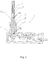
- the invention relates to an illumination device 1 with a multicolored light source 8, which couples light into a light guide 2 via an elongate light mixer 5.
- the light guide 2 is fixed at one end 22 opposite the light mixer 5 .
- the light source 8 is positioned on the end face 23 of the light mixer 5 .
- the light guide 2 is permanently connected at its one end 22 to the light mixer 5 via an injection molding sprue.
- the length of the light mixer 5 is designed in such a way that at least 60% of the incoming light undergoes at least two internal reflections before it is coupled into the light guide 2 .
- the injection molding sprue of light guide 2 and light mixer 5 can be fixed via a mechanical strain relief clamp 6.
- the strain relief clip 6 can be designed as a ferrule, in particular a crimp ferrule.
- the strain relief clamp 6 forms a mounting element that exerts a fixing force on the light guide 2, in particular when the light guide 2 is designed as a light guide bundle, in particular a fiber bundle, and is therefore pliable foothills.
- the light guide bundle can be surrounded by a hose 21 .
- the light guide bundle can be formed by thread ends of a textile fabric.
- the light mixer 5 is preferably designed to be rigid.
- the light mixer 5 is transparent and has at least three different regions 25, 26, 27 with different optical reflection or transmission properties over its entire length. For example, only the inclination of the edge surfaces changes between the regions 25, 26, 27. This actually involves other reflection angles. Both the material and the surface can remain the same and the transmission properties cannot change in this respect.
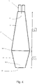
- the light mixer 5 is also preferably formed with a first end 25.1 of a first region 25 in the direction of the light source 8, a second end 27.1 of a second region 27 in the direction of the fiber bundle 2 and a transition area of a third region 26 lying in between.
- the light mixer 5 is preferably designed in the shape of a club.
- the first end 25.1 then preferably has a first nominal width qE, which is larger than a second nominal width qA of the second end 27.1, and the first qE and the second qA nominal width are then preferably smaller than a third nominal width qV of the transition area of the third region 26 with a maximum thickening of an outer contour of the light mixer 5.
- the light mixer 5 is designed to reflect the light rays passing through it by total internal reflection.
- the light mixer 5 has a correspondingly high refractive index of the material, which is preferably in the range from 1.4 to 1.8.
- Suitable materials are glass or plastic materials, the consistency of which can be selected. It can also be optical be applied to the light mixer 5 effective coatings. It is preferably decisive that the total reflection taking place in the light mixer 5, which is caused by its shape and its material, meets the requirements of the objective with regard to the mixing of the light and the maximization of the efficiency.
- the different regions 25, 26, 27 selected for the light mixer 5, which differ in their three-dimensional shape, for example, are also important for the optical reflection or transmission properties of the light guide in order to affect the direction of the light beams reflected in the light mixer 5.
- the first region 25 forms a reflection zone due to an axially widening cross section, so that, for example, the number of reflections is increased, which has an advantageous effect on a mixture of different light colors.
- the first region 25 can thus be used like a bowl to optimize the beam entrance.
- a maximum nominal width qV is reached in the transition area of the third region 26, the axial extension of which can in turn be selected in order to give the light mixer 5 a central rod-shaped section, for example.
- the cross section of the light mixer 5 in the second region 27 tapers towards the second end 27.1. A so-called funnel effect is established, which serves to direct the light in relation to the second end 27.1 for coupling into the fiber end 22.
- the second region 2 shows the course of the light rays for the light mixer 5 described above and illustrates the coupling of light into the light guide 2 with increased intensity.
- the broadening in the first region 25 up to the third region 26 with a third nominal width leads to focusing on the end 27.1 of the second region 27 and thus on one end of the mixing lens formed by the light mixer 5.
- a larger nominal width of the first end 25.1 opposite the light source 8 can be used for optimal coupling of the light, since the cross-sectional change towards a smaller nominal diameter of the second region 27 then no longer leads to a significant loss of intensity.
- the third nominal width qV of the transition area in the third region 26 is a maximum of 1.5 times the first nominal width qE of the first region 25 and thus the nominal width of the coupling to the light source 8 .
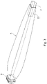
- the light mixer 5 can alternatively also have a cuboid three-dimensional shape, although the design variants described above for the first, second and third nominal width of the regions 25, 26, 27 apply unchanged.
- the light mixer 5 should meet at least two requirements: on the one hand, ensuring adequate color mixing over the shortest possible distance and, on the other hand, increasing the efficiency with a reduction in the cross section from the first end 25.1 (coupling cross section) to the second end 27.1 ( outlet cross-section).
- the three sizes described above are of the same shape, but this is not mandatory.
- Possible cross-sectional shapes include square, round, elliptical, trigonal, tetragonal, pentagonal, hexagonal, heptagonal, etc.
- a total length of the light mixer 5 is preferably formed with a length LE of the first region 25 and a length LA of the second region 27.
- the length ratio of these regions 25, 27 can be divided such that, for example, the second region 27 is 3 to 6 times is 25 in length of the first region.
- the third region 26 can be limited to a transition plane as a transition area of the maximum thickening, as in FIG 4 is shown. Alternatively, region 26 may define a length between first region 25 and second region 27 .
- the third nominal width qV in the transition area of the third region 26 is preferably less than 3 times the second nominal width qA of the second end 27.1 in the area of the decoupling surface of the light mixer 5 amounts to.
- the third nominal width qV is less than twice the second nominal width qA of the second end 27.1 in the area of the decoupling surface. This achieves an optimization with regard to a reduction in the cross-sectional changes.
- a fiber bundle of the light guide 2 can also be integrated at this end into the light mixer 5 in the area of the injection molding sprue.
- the fibers of the light guide 2 can then be fused as a unit to form the light mixer 5 .
- the special feature here is that this process can be carried out in an injection molding process.
- the fibers of the light guide 2 preferably fuse with the light mixer material, for example PMMA, PC.
- Another advantage is the reduction in the number of components required.
- the result is a one-piece production, with the light mixer 5 being optically designed, as described above, with preferably at least three different regions 25, 26, 27.
- 8 multicolored LEDs in particular RGB LEDs, can be used as the light source.
- Light of several wavelengths in particular light of three different wavelengths and/or light of the colors red, green and blue, can thus be coupled in and out.
- the LEDs and the light mixer 5 are then preferably positioned perpendicular to one another.
- the light mixer 5 is preferably formed from a plastic such as PMMA or polycarbonate.
- a light guide which preferably has a rigid part which is used for light mixing and has a preferably considerably larger flexible part which is used for light distribution and light emission.
- the preferably limp part can be designed in such a way that it guides light into at least two delimited areas.
- the light can be guided in such a way that no further interface is passed from entering the overall system (rigid and limp) in the rigid part to exiting in the limp part.
- the light-guiding part of the system can therefore have a common outer optical interface.
- the rigid part can be designed in such a way that 60% of the guided beams undergo at least two internal reflections before they merge into the rigid part.
- the pliable portion can be encased with an optically low-density polymer. Extensions of the material encasing the flexible part can protrude into the rigid part of the light guide for better mechanical adhesion.
- the limp portion can also be polygonal and have one or more tapers and widenings. Furthermore, latching elements can be provided on the rigid part.
- the limp part of the light guide can be designed in the form of a textile surface. Woven fabrics, knitted fabrics, warp-knitted fabrics or non-crimp fabrics are particularly preferred, but not exhaustive. Finally, the limp part can be encased either directly or indirectly by another translucent layer.
Landscapes
- Physics & Mathematics (AREA)
- General Physics & Mathematics (AREA)
- Optics & Photonics (AREA)
- Non-Portable Lighting Devices Or Systems Thereof (AREA)
- Light Guides In General And Applications Therefor (AREA)
- Optical Couplings Of Light Guides (AREA)
Description
- Die Erfindung betrifft eine Beleuchtungsvorrichtung mit einer mehrfarbigen Lichtquelle nach dem Oberbegriff des Anspruchs 1.
- Aus
EP 3 270 050 A1 ist eine gattungsgemäße Beleuchtungsvorrichtung bekannt. - Aus
DE 10 2010 046 342 B4 ist eine Beleuchtungsvorrichtung mit einer Kopplungsvorrichtung zur Einkopplung von Licht eines Leuchtmittels in einen Lichtleiter eines Fahrzeugs bekannt. Der Lichtleiter kann sich dabei aus einem Glasfaserbündel zusammensetzen. Für die Beleuchtung des Innenraums eines Kraftwagens werden zunehmend Lichtleiter eingesetzt, welche das Licht einer Lichtquelle sehr variabel an verschiedene Orte im Innenraum des Kraftwagens weiterleiten können. In der Regel werden die Lichtleiter durch Glasfasern gebildet, während als Lichtquelle zunehmend moderne Leuchtmittel, wie z.B. LEDs, Verwendung finden. Für eine hohe Lichtausbeute ist es erforderlich, das Licht der Lichtquelle möglichst effizient in den Lichtleiter einzukoppeln. Üblicherweise befindet sich die Lichtquelle direkt an der Stirnfläche des Lichtleiters, so dass das Licht senkrecht auf die Lichtleiterfläche auftritt. Das Licht der Lichtquelle trifft dann nur in der Mitte des Lichtleiters ideal auf. Je entfernter das Licht von der Mitte auftritt, desto ungünstiger werden die Einkopplungswerte. Werden als Lichtquelle mehrfarbige LEDs verwendet, so kann sich eine schlechte Farbmischung ergeben. Die Kopplungsvorrichtung umfasst daher einen Hohlkörper mit einer zumindest teilweise reflektierenden Innenwand, wobei die Innenwand unterschiedliche Reflexionskoeffizienten für verschiedene Lichtfarben aufweisen kann. Nachteilig ist jedoch, dass trotz allem das ausgestrahlte Licht keine hinreichende Homogenität hinsichtlich Farbe und Intensität aufweist. - Der Erfindung liegt daher die Aufgabe zugrunde, eine Beleuchtungsvorrichtung zu schaffen, die einfach aufgebaut ist und bei der die Homogenität des Lichts hinsichtlich Farbe und/oder Intensität verbessert ist.
- Diese Aufgabe wird durch die Merkmale des Anspruchs 1 gelöst.
- Hierdurch wird eine Beleuchtungsvorrichtung geschaffen, die mit wenig Aufwand den Lichtmischer derart verbessert, dass eine Fokussierung des Strahlenverlaufs bei signifikant reduziertem Verlust erreicht wird. Zum einen wird nämlich eine bessere Durchmischung des Lichts, z.B. des Rot-, Grün- und Blau-Anteils einer RGB-LED, und zum anderen eine Reduzierung der Verluste bei der Einkopplung in einen Zielquerschnitt erreicht, welcher vorzugsweise kleiner als der Querschnitt der Emitterfläche ist.
- Weitere Vorteile und Ausgestaltungen der Erfindung sind der nachfolgenden Beschreibung und den Unteransprüchen zu entnehmen.
- Die Erfindung wird nachstehend anhand der in den beigefügten Abbildungen dargestellten Ausführungsbeispiele näher erläutert.
-
Fig. 1 zeigt schematisch einen Schnitt einer Beleuchtungsvorrichtung gemäß einem ersten Ausführungsbeispiel, -
Fig. 2 zeigt schematisch einen Strahlenverlauf in einem Lichtmischer einer Beleuchtungsvorrichtung nachFig. 1 , -
Fig. 3 zeigt schematisch eine perspektivische Ansicht eines Lichtmischers einer Beleuchtungsvorrichtung nachFig. 1 , -
Fig. 4 zeigt schematisch einen Längsschnitt eines Lichtleiters eines Lichtmischers einer Beleuchtungsvorrichtung nachFig. 1 , -
Fig. 5 zeigt schematisch eine Ansicht einer Beleuchtungsvorrichtung gemäß einem weiteren Ausführungsbeispiel. - Wie
Fig. 1 zeigt, betrifft die Erfindung eine Beleuchtungsvorrichtung 1 mit einer mehrfarbigen Lichtquelle 8, die Licht über einen länglich ausgebildeten Lichtmischer 5 in einen Lichtleiter 2 einkoppelt. Der Lichtleiter 2 ist dazu an seinem einen Ende 22 gegenüber dem Lichtmischer 5 fixiert. Die Lichtquelle 8 ist zur Stirnfläche 23 des Lichtmischers 5 positioniert. Der Lichtleiter 2 ist an seinem einen Ende 22 über einen spritzgießtechnischen Anguss mit dem Lichtmischer 5 dauerhaft verbunden. Ferner ist der Lichtmischer 5 auf seiner Länge derart ausgelegt, dass mindestens 60 % des eintretenden Lichts mindestens zwei innere Reflexionen vor der Einkopplung in den Lichtleiter 2 erfährt. - Wie
Fig. 5 zeigt, ist kann der spritztechnische Anguss von Lichtleiter 2 und Lichtmischer 5 über eine mechanische Zugentlastungsschelle 6 fixiert. Die Zugentlastungsschelle 6 kann als Ferrule, insbesondere Crimpferrule, ausgebildet sein. Die Zugentlastungsschelle 6 bildet ein Halterungselement, das eine fixierende Kraft auf den Lichtleiter 2 ausübt insbesondere dann, wenn der Lichtleiter 2 als ein Lichtleiterbündel, insbesondere Faserbündel, ausgebildet ist und damit biegeschlaffe Ausläufer bildet. Das Lichtleiterbündel kann von einem Schlauch 21 umgeben sein. Das Lichtleiterbündel kann alternativ von Fadenenden eines textilen Flächengebildes gebildet sein. Demgegenüber ist der Lichtmischer 5 vorzugsweise biegesteif ausgebildet. - Erfindungsgemäß ist vorgesehen, dass der Lichtmischer 5 transparent ist und auf seiner Gesamtlänge mindestens drei verschiedene Regionen 25, 26, 27 mit unterschiedlichen optischen Reflexions- oder Übertragungseigenschaften aufweist. Beispielsweise ändert sich zwischen den Regionen 25, 26, 27 nur die Neigung der Randflächen. Damit sind dann tatsächlich andere Reflexionswinkel verbunden. Dabei können sowohl das Material als auch die Oberfläche gleich bleiben und insoweit die Übertragungseigenschaften nicht ändern.
- Wie insbesondere
Fig. 4 zeigt, ist der Lichtmischer 5 ferner vorzugsweise mit einem in Richtung der Lichtquelle 8 liegenden ersten Ende 25.1 einer ersten Region 25, einem in Richtung des Faserbündels 2 liegenden zweiten Ende 27.1 einer zweiten Region 27 und einem dazwischenliegenden Übergangsbereich einer dritten Region 26 ausgebildet. - Wie weiterhin in den
Fig. 1 bis Fig. 4 dargestellt ist, ist der Lichtmischer 5 vorzugsweise keulenförmig ausgebildet. Das erste Ende 25.1 weist dann vorzugsweise eine erste Nennweite qE auf, die größer ist als eine zweite Nennweite qA des zweiten Endes 27.1, und die erste qE und die zweite qA Nennweite sind dann vorzugsweise kleiner als eine dritte Nennweite qV des Übergangsbereichs der dritten Region 26 mit einer maximalen Verdickung einer Außenkontur des Lichtmischer 5. - Der Lichtmischer 5 ist zur Reflexion der durch ihn hindurchtretenden Lichtstrahlen durch innere Totalreflexion ausgeführt. Dazu besitzt der Lichtmischer 5 bedingt durch das verwendete Material einen entsprechend hohen Brechungsindex des Materials, der vorzugsweise im Bereich von 1,4 bis 1,8 liegt. Geeignete Materialien sind Glas oder Plastwerkstoffe, deren Konsistenz wählbar ist. Es können auch optisch wirksame Beschichtungen auf den Lichtmischer 5 aufgebracht sein. Entscheidend ist vorzugsweise, dass die im Lichtmischer 5 stattfindende, durch seine Form und sein Material bedingte Totalreflexion den Anforderungen der Zielsetzung hinsichtlich Durchmischung des Lichts und der Maximierung der Effizienz gerecht wird.
- Wesentlich für die optischen Reflexions- oder Übertragungseigenschaften des Lichtleiters sind darüber hinaus die für den Lichtmischer 5 gewählten verschiedenen Regionen 25, 26, 27, die sich beispielsweise in ihrer Raumform unterscheiden, um auf die Richtung der im Lichtmischer 5 reflektierten Lichtstrahlen einzuwirken.
- Wie beispielsweise
Fig.4 zeigt, bildet die erste Region 25 bedingt durch einen axial sich erweiternden Querschnitt eine Reflexionszone, damit beispielsweise die Anzahl an Reflexionen erhöht wird, was sich vorteilhaft auf eine Mischung unterschiedlicher Lichtfarben auswirkt. Die erste Region 25 kann also schüsselartig zur Optimierung des Strahleneingangs genutzt werden. Im Übergangsbereich der dritten Region 26 wird eine maximale Nennweite qV erreicht, deren axiale Erstreckung wiederum wählbar ist, um dem Lichtmischer 5 beispielsweise einen mittigen stabförmigen Abschnitt zu verleihen. Hin zum zweiten Ende 27.1 verjüngt sich der Querschnitt des Lichtmischers 5 in der zweiten Region 27. Ein sogenannter Trichtereffekt wird begründet, der dazu dient, das Licht zu richten in Bezug auf das zweite Ende 27.1 zur Einkopplung in das Faserende 22. -
Fig. 2 zeigt den Lichtstrahlenverlauf für den vorstehend beschriebenen Lichtmischer 5 und verdeutlicht die Einkopplung von Licht in den Lichtleiter 2 mit erhöhter Intensität. Wie im Strahlenverlauf gemäßFig. 2 gezeigt, führt die Verbreiterung in der ersten Region 25 bis hin zur dritten Region 26 mit einer dritten Nennweite zu einer Fokussierung auf das Ende 27.1 der zweiten Region 27 und damit auf ein Ende der von dem Lichtmischer 5 gebildeten Mischlinse. Eine größere Nennweite des ersten Endes 25.1 gegenüberliegend der Lichtquelle 8 kann so genutzt werden zur optimalen Einkopplung des Lichts, da die Querschnittsveränderung hin zu einer kleineren Nennweite der zweiten Region 27 dann zu keinem signifikanten Intensitätsverlust mehr führt. Vorteilhaft ist insoweit, dass die dritte Nennweite qV des Übergangsbereichs in der dritten Region 26 maximal das 1,5-fache der ersten Nennweite qE der ersten Region 25 und damit der Nennweite der Einkopplung an der Lichtquelle 8 beträgt. - Wie
Fig. 3 zeigt, kann der Lichtmischer 5 alternativ auch eine quaderförmige Raumform besitzen, wobei jedoch die zuvor beschriebenen Gestaltungsvarianten zur ersten, zweiten und dritten Nennweite der Regionen 25, 26, 27 unverändert gelten. Der Lichtmischer 5 sollte in seiner Funktion als Mischlinse nämlich mindestens zwei Anforderungen erfüllen: Zum einen die Gewährleistung einer hinreichenden Farbmischung auf möglichst kurzer Strecke und zum anderen eine Steigerung der Effizienz bei einer Reduzierung des Querschnitts vom ersten Ende 25.1 (Einkopplungsquerschnitt) zum zweiten Ende 27.1 (Austrittsquerschnitt). - Vorzugsweise sind die drei vorstehend beschriebenen Nennweiten von derselben Form, was aber nicht zwingend erforderlich ist. Mögliche Querschnittsformen sind unter anderem quadratisch, rund, elliptisch, trigonal, tetragonal, pentagonal, hexagonal, heptagonal, usw.
- Eine Gesamtlänge des Lichtmischers 5 ist vorzugsweise ausgebildet mit einer Länge LE der ersten Region 25 und einer Länge LA der zweiten Region 27. Das Längenverhältnis dieser Regionen 25, 27 kann derart aufgeteilt sein, dass beispielsweise die zweite Region 27 das 3- bis 6-fache an Länge der ersten Region 25 besitzt. Die dritte Region 26 kann als Übergangsbereich der maximalen Verdickung auf eine Übergangsebene beschränkt sein, wie in
Fig. 4 dargestellt ist. Alternativ kann die Region 26 eine Länge zwischen der ersten Region 25 und der zweiten Region 27 definieren. Hinsichtlich der Nennweiten qE, qA und qV ist beispielsweise vorgesehen, dass die dritte Nennweite qV im Übergangsbereich der dritten Region 26 vorzugsweise weniger als das 3-fache der zweiten Nennweite qA des zweiten Endes 27.1 im Bereich der Auskopplungsfläche des Lichtmischers 5 beträgt. Bei den inFig. 2 undFig. 3 gezeigten Ausführungsbeispielen des Lichtmischers 5 ist vorgesehen, dass die dritte Nennweite qV weniger als das 2-fache der zweiten Nennweite qA des zweiten Endes 27.1 im Bereich der Auskopplungsfläche beträgt. Hierdurch wird eine Optimierung bezüglich einer Reduzierung der Querschnittsveränderungen erreicht. - Ein Faserbündel des Lichtleiters 2 kann an diesem Ende auch in den Lichtmischer 5 im Bereich des spritzgießtechnischen Angusses eingebunden sein. Die Fasern des Lichtleiters 2 können dann als eine Einheit zum Lichtmischer 5 verschmolzen sein.
- Die Besonderheit ist hier, dass dieser Vorgang in einem Spritzgussprozess erfolgen kann. Dabei verschmelzen vorzugsweise die Fasern des Lichtleiters 2 mit dem Lichtmischerwerkstoff, beispielsweise PMMA, PC. Ein Vorteil liegt auch in der Verringerung der notwendigen Bauteile. Eine einstückige Herstellung ist das Ergebnis, wobei der Lichtmischer 5 wie zuvor beschrieben optisch ausgebildet ist mit vorzugsweise mindestens drei verschiedenen Regionen 25, 26, 27.
- Wie bereits ausgeführt, können als Lichtquelle 8 mehrfarbige LEDs, insbesondere RGB LEDs, verwendet werden. Ein- und auskoppelbar ist somit Licht mehrerer Wellenlängen, insbesondere Licht dreier unterschiedlicher Wellenlängen und/oder Licht der Farben rot, grün und blau.
- Die LEDs und der Lichtmischer 5 sind dann vorzugsweise senkrecht zueinander positioniert. Der Lichtmischer 5 ist vorzugsweise gebildet aus einem Kunststoff wie beispielsweise PMMA oder Polycarbonat.
- Erfindungsgemäß ist folglich ein Lichtleiter vorgesehen, der vorzugsweise einen biegesteifen Teil aufweist, welcher der Lichtmischung dient und einen vorzugsweise erheblich größeren biegeschlaffen Anteil aufweist, welcher zur Lichtverteilung und Lichtemission dient. Der vorzugsweise biegeschlaffe Anteil kann so ausgeführt sein, dass er Licht in mindestens zwei abgegrenzte Bereiche führt.
- Das Licht kann hierbei so geführt sein, dass vom Eintritt in das Gesamtsystem (biegesteif und biegeschlaff) im biegesteifen Teil bis zum Austritt im biegeschlaffen Teil keine weitere Grenzfläche passiert wird. Der lichtführende Teil des Systems kann also über eine gemeinsame äußere optische Grenzfläche verfügen. Wie bereits vorstehend ausgeführt, kann der biegesteife Teil so ausgebildet sein, dass 60 % der geführten Strahlen mindestens zwei interne Reflexionen durchlaufen, bevor sie in den biegeschlaffen Teil übergehen.
- Dabei kann der biegeschlaffe Anteil mit einem Polymer optisch niedriger Dichte ummantelt sein. Ausläufer des den biegeschlaffen Teil ummantelnden Materials können in den biegesteifen Teil des Lichtleiters hineinragen für eine bessere mechanische Haftung. Der biegeschlaffe Anteil kann ferner vieleckig ausgeführt sein und über eine oder mehrere Verjüngungen und Ausweitungen verfügen. An dem biegesteifen Teil können ferner Verrastungselemente vorgesehen sein.
- Der biegeschlaffe Teil des Lichtleiters kann in Form einer textilen Fläche ausgeführt sein. Besonders bevorzugt, aber nicht abschließend, werden genannt Gewebe, Gestrick, Gewirk oder Gelege. Schließlich kann der biegeschlaffen Teil durch eine weitere transluzente Schicht entweder direkt oder indirekt ummantelt sein.
Claims (8)
- Beleuchtungsvorrichtung mit einer mehrfarbigen Lichtquelle (8), die Licht über einen länglich ausgebildeten Lichtmischer (5) in einen Lichtleiter (2) einkoppelt, wozu der Lichtleiter (2) an seinem einen Ende (22) gegenüber dem Lichtmischer (5) fixiert ist, und die Lichtquelle (8) zur Stirnfläche (23) des Lichtmischers (5) positioniert ist, wobei der Lichtleiter (2) als Lichtleiterbündel ausgebildet ist und der Lichtmischer (5) auf seiner Länge derart ausgelegt ist, dass mindestens 60 % des eintretenden Lichts mindestens zwei innere Reflexionen vor der Einkopplung in den Lichtleiter (2) erfährt, dadurch gekennzeichnet, dass das Lichtleiterbündel von Fadenenden eines textilen Flächengebildes ausgebildet ist und der Lichtleiter an seinem einen Ende (22) über einen spritzgießtechnischen Anguss mit dem Lichtmischer (5) dauerhaft verbunden ist, wobei der spritzgießtechnische Anguss von Lichtleiter (2) und Lichtmischer (5) über eine mechanische Zugentlastungsschelle fixiert ist.
- Beleuchtungsvorrichtung nach Anspruch 1, dadurch gekennzeichnet, dass die Zugentlastungsschelle als Ferrule ausgebildet ist.
- Beleuchtungsvorrichtung nach einem der Ansprüche 1 bis 2, dadurch gekennzeichnet, das der Lichtmischer (5) auf seiner Gesamtlänge mindestens drei verschiedene Regionen (25, 26, 27) mit unterschiedlichen optischen Reflexions- oder Übertragungseigenschaften aufweist.
- Beleuchtungsvorrichtung (1) nach einem der Ansprüche 1 bis 3, dadurch gekennzeichnet, dass der Lichtleiter (2) keulenförmig ausgebildet ist, wobei ein erstes Ende (25.1) eine erste Nennweite (qE) aufweist, die größer ist als eine zweite Nennweite (qA) eines zweiten Endes (27.1), und die erste (qE) und die zweite (qA) Nennweite kleiner sind als eine dritte Nennweite (qV) eines Übergangsbereichs einer dritten Region (26) mit einer maximalen Verdickung einer Außenkontur des Lichtleiters (2).
- Beleuchtungsvorrichtung nach Anspruch 4, dadurch gekennzeichnet, dass eine Gesamtlänge des Lichtleiters (2) des Lichtmischers (5) das 3- bis 6-fache der dritten Nennweite (qV) des Übergangsbereichs einer dritten Region (26) mit maximaler Verdickung beträgt.
- Beleuchtungsvorrichtung (1) nach einem der Ansprüche 1 bis 3, dadurch gekennzeichnet, dass der Lichtleiter (2) des Lichtmischers (5) faserseitig eine Stirnfläche aufweist, die direkt stoßseitig an einem Ende (22) des Faserbündels anschließt.
- Beleuchtungsvorrichtung nach einem der Ansprüche 1 bis 6, dadurch gekennzeichnet, dass als Lichtquelle (8) mehrfarbige LEDs verwendet werden.
- Beleuchtungsvorrichtung (1) nach Anspruch 1, dadurch gekennzeichnet, dass der Lichtleiter (2) und der Lichtmischer (5) aus demselben Kunststoff wie beispielsweise PMMA oder Polycarbonat gebildet sind
Applications Claiming Priority (1)
| Application Number | Priority Date | Filing Date | Title |
|---|---|---|---|
| DE102018001029.6A DE102018001029A1 (de) | 2018-02-08 | 2018-02-08 | Beleuchtungsvorrichtung mit einem seitenemittierenden lichtleitenden Faserbündel |
Publications (2)
| Publication Number | Publication Date |
|---|---|
| EP3525017A1 EP3525017A1 (de) | 2019-08-14 |
| EP3525017B1 true EP3525017B1 (de) | 2022-08-31 |
Family
ID=65365768
Family Applications (2)
| Application Number | Title | Priority Date | Filing Date |
|---|---|---|---|
| EP19000073.7A Active EP3524877B1 (de) | 2018-02-08 | 2019-02-07 | Beleuchtungsvorrichtung mit einem seitenemittierenden lichtleitenden faserbündel |
| EP19000074.5A Active EP3525017B1 (de) | 2018-02-08 | 2019-02-08 | Beleuchtungsvorrichtung mit lichtleiter und lichtmischer für eine mehrfarbige lichtquelle |
Family Applications Before (1)
| Application Number | Title | Priority Date | Filing Date |
|---|---|---|---|
| EP19000073.7A Active EP3524877B1 (de) | 2018-02-08 | 2019-02-07 | Beleuchtungsvorrichtung mit einem seitenemittierenden lichtleitenden faserbündel |
Country Status (2)
| Country | Link |
|---|---|
| EP (2) | EP3524877B1 (de) |
| DE (1) | DE102018001029A1 (de) |
Cited By (1)
| Publication number | Priority date | Publication date | Assignee | Title |
|---|---|---|---|---|
| EP4488974A1 (de) | 2023-07-04 | 2025-01-08 | Bizerba SE & Co. KG | Verkaufsvorrichtung |
Families Citing this family (7)
| Publication number | Priority date | Publication date | Assignee | Title |
|---|---|---|---|---|
| CN113188083B (zh) * | 2021-05-12 | 2022-10-14 | 荣成康派斯新能源车辆股份有限公司 | 一种智能发光星空车顶 |
| DE102021123276A1 (de) * | 2021-09-08 | 2023-03-09 | HELLA GmbH & Co. KGaA | Lichtleiter-Kopplungseinrichtung und Verfahren zu deren Herstellung |
| FR3128765B1 (fr) * | 2021-10-29 | 2023-11-17 | Valeo Vision | Module optique d’un dispositif lumineux d’un véhicule automobile |
| CN114347896A (zh) * | 2021-12-31 | 2022-04-15 | 宁波福尔达智能科技股份有限公司 | 一种rgb氛围灯灯头、氛围灯及车辆 |
| CN114312556A (zh) * | 2021-12-31 | 2022-04-12 | 宁波福尔达智能科技股份有限公司 | 一种氛围灯总成、车辆门板及车辆 |
| DE102022207724A1 (de) * | 2022-07-27 | 2024-02-01 | UNO MINDA Europe GmbH | Beleuchtungsmodul |
| EP4382800B1 (de) | 2022-12-06 | 2025-12-10 | Hella Gmbh & Co. Kgaa | Beleuchtungsvorrichtung für ein fahrzeug und fahrzeug mit solch einer beleuchtungsvorrichtung |
Family Cites Families (14)
| Publication number | Priority date | Publication date | Assignee | Title |
|---|---|---|---|---|
| US5271079A (en) * | 1991-11-08 | 1993-12-14 | Finisar Corporation | Light mixing device with fiber optic output |
| DE10139578A1 (de) * | 2001-08-10 | 2003-04-10 | Hella Kg Hueck & Co | Innenleuchte für Fahrzeuge |
| DE10236499A1 (de) * | 2002-08-09 | 2004-02-26 | Sidler Gmbh & Co. | Fahrzeugleuchtenanordnung mit biegsamem Lichtleiter |
| US6937791B2 (en) * | 2003-05-02 | 2005-08-30 | The Boeing Company | Optical coupling apparatus and method |
| DE102006004996A1 (de) * | 2005-02-01 | 2006-08-24 | Schott Ag | Lichtmischer für LED |
| DE102007014871B4 (de) | 2007-03-26 | 2012-09-27 | Schott Ag | Beleuchtungseinrichtung, insbesondere für Fahrzeuge |
| DE102008009138A1 (de) * | 2008-02-14 | 2009-08-27 | Schott Ag | Seitenemittierende brechwertangepasste Faser |
| DE102008044938B4 (de) * | 2008-08-29 | 2013-10-10 | Schott Ag | Verfahren zur Terminierung von lichtleitenden Faserbündeln sowie Hülse mit einem Faserbündel |
| DE102009037625A1 (de) * | 2009-08-14 | 2011-02-17 | Automotive Lighting Reutlingen Gmbh | Beleuchtungseinrichtung für ein Kraftfahrzeug |
| DE102010046342B4 (de) | 2010-09-23 | 2012-11-08 | Audi Ag | Beleuchtungsvorrichtung sowie Fahrzeug mit einer Beleuchtungsvorrichtung |
| EP2656123B1 (de) * | 2010-12-23 | 2022-05-11 | Harman Professional Denmark ApS | Optischer lichtmischer zur bereitstellung eines homogenen und gleichmässigen lichtstrahls |
| DE102012022716A1 (de) * | 2012-11-21 | 2013-05-29 | Daimler Ag | Mischen und Einkoppeln von Licht in einen Lichtleiter mittels einer Umlenkvorrichtung und einem Mischerstab |
| DE102015106049C5 (de) | 2015-04-21 | 2022-11-03 | Schott Ag | Beleuchtungsvorrichtung mit seitenemittierendem lichtleitenden Faserbündel |
| US10240746B2 (en) * | 2016-07-14 | 2019-03-26 | Valeo North America, Inc. | Fiber optic light panel with homogeneous light output |
-
2018
- 2018-02-08 DE DE102018001029.6A patent/DE102018001029A1/de active Pending
-
2019
- 2019-02-07 EP EP19000073.7A patent/EP3524877B1/de active Active
- 2019-02-08 EP EP19000074.5A patent/EP3525017B1/de active Active
Cited By (1)
| Publication number | Priority date | Publication date | Assignee | Title |
|---|---|---|---|---|
| EP4488974A1 (de) | 2023-07-04 | 2025-01-08 | Bizerba SE & Co. KG | Verkaufsvorrichtung |
Also Published As
| Publication number | Publication date |
|---|---|
| DE102018001029A1 (de) | 2019-08-08 |
| EP3525017A1 (de) | 2019-08-14 |
| EP3524877B1 (de) | 2022-07-20 |
| EP3524877A1 (de) | 2019-08-14 |
Similar Documents
| Publication | Publication Date | Title |
|---|---|---|
| EP3525017A1 (de) | Beleuchtungsvorrichtung mit lichtleiter und lichtmischer für eine mehrfarbige lichtquelle | |
| DE10158336B4 (de) | Leuchte für Fahrzeuge | |
| EP2317212B1 (de) | Beleuchtungseinrichtung für ein Kraftfahrzeug | |
| EP3086027B1 (de) | Beleuchtungsvorrichtung mit seitenemittierendem lichtleitenden faserbündel | |
| EP2028510B1 (de) | Beleuchtungseinrichtung, insbesondere für Fahrzeuge | |
| EP0933587B1 (de) | Stabförmiger Lichtleiter | |
| EP2857740B1 (de) | Kfz-Beleuchtungseinrichtung | |
| DE102008021290B4 (de) | Lichtleiterstruktur für eine Kraftfahrzeugbeleuchtungseinrichtung und Kraftfahrzeugbeleuchtungseinrichtung mit einer solchen Lichtleiterstruktur | |
| EP2538130A1 (de) | Optisches System mit einer Lichteinkopplung von Licht punktförmiger Lichtquellen in einen flächigen Lichtleiter | |
| EP3450834A1 (de) | Beleuchtungs- und/oder signalisierungsvorrichtung für ein kraftfahrzeug | |
| EP3190332A1 (de) | Beleuchtungseinheit für ein kraftfahrzeug | |
| DE102019123694A1 (de) | Seitenemittierender Lichtleiter und Verfahren zu dessen Herstellung | |
| DE102008034052B4 (de) | Lichtleitkörper zur Anwendung als Positionslicht oder als Tagfahrlicht für ein Kraftfahrzeug | |
| DE102016210363A1 (de) | Beleuchtungseinrichtung für ein Kraftfahrzeug, Kraftfahrzeug mit Beleuchtungseinrichtung und Verfahren zum Betreiben einer Beleuchtungseinrichtung | |
| EP3803195A1 (de) | Beleuchtungsvorrichtung für einen kraftfahrzeugscheinwerfer | |
| DE102006037797B4 (de) | Kraftfahrzeugleuchte | |
| DE102012211284A1 (de) | Lichtleitelement und Lichtleiter | |
| DE102012209337A1 (de) | Lichtleiter und Lichtleitervorrichtung | |
| DE102013204021A1 (de) | Lichtleiter für eine Beleuchtungseinrichtung | |
| DE19939087A1 (de) | Lichtleiter | |
| DE102011011462A1 (de) | Lichtleitelement mit Auskoppelstellen | |
| DE102012112125A1 (de) | Beleuchtungsvorrichtung für Fahrzeuge | |
| DE4219901A1 (de) | Lichtwellenleiter-Abschlußhülse | |
| DE102005059958A1 (de) | Beleuchtungseinrichtung | |
| DE10250912B4 (de) | Einkoppelvorrichtung |
Legal Events
| Date | Code | Title | Description |
|---|---|---|---|
| PUAI | Public reference made under article 153(3) epc to a published international application that has entered the european phase |
Free format text: ORIGINAL CODE: 0009012 |
|
| STAA | Information on the status of an ep patent application or granted ep patent |
Free format text: STATUS: THE APPLICATION HAS BEEN PUBLISHED |
|
| AK | Designated contracting states |
Kind code of ref document: A1 Designated state(s): AL AT BE BG CH CY CZ DE DK EE ES FI FR GB GR HR HU IE IS IT LI LT LU LV MC MK MT NL NO PL PT RO RS SE SI SK SM TR |
|
| AX | Request for extension of the european patent |
Extension state: BA ME |
|
| STAA | Information on the status of an ep patent application or granted ep patent |
Free format text: STATUS: REQUEST FOR EXAMINATION WAS MADE |
|
| 17P | Request for examination filed |
Effective date: 20200213 |
|
| RBV | Designated contracting states (corrected) |
Designated state(s): AL AT BE BG CH CY CZ DE DK EE ES FI FR GB GR HR HU IE IS IT LI LT LU LV MC MK MT NL NO PL PT RO RS SE SI SK SM TR |
|
| RIN1 | Information on inventor provided before grant (corrected) |
Inventor name: KRETSCHMER, STEFAN Inventor name: KUEMPFEL, THOMAS Inventor name: MOHR, BENJAMIN Inventor name: WILMS, HANS-WALTER |
|
| STAA | Information on the status of an ep patent application or granted ep patent |
Free format text: STATUS: EXAMINATION IS IN PROGRESS |
|
| 17Q | First examination report despatched |
Effective date: 20201023 |
|
| GRAP | Despatch of communication of intention to grant a patent |
Free format text: ORIGINAL CODE: EPIDOSNIGR1 |
|
| STAA | Information on the status of an ep patent application or granted ep patent |
Free format text: STATUS: GRANT OF PATENT IS INTENDED |
|
| INTG | Intention to grant announced |
Effective date: 20220321 |
|
| GRAS | Grant fee paid |
Free format text: ORIGINAL CODE: EPIDOSNIGR3 |
|
| GRAA | (expected) grant |
Free format text: ORIGINAL CODE: 0009210 |
|
| STAA | Information on the status of an ep patent application or granted ep patent |
Free format text: STATUS: THE PATENT HAS BEEN GRANTED |
|
| AK | Designated contracting states |
Kind code of ref document: B1 Designated state(s): AL AT BE BG CH CY CZ DE DK EE ES FI FR GB GR HR HU IE IS IT LI LT LU LV MC MK MT NL NO PL PT RO RS SE SI SK SM TR |
|
| REG | Reference to a national code |
Ref country code: CH Ref legal event code: EP Ref country code: GB Ref legal event code: FG4D Free format text: NOT ENGLISH |
|
| REG | Reference to a national code |
Ref country code: AT Ref legal event code: REF Ref document number: 1515708 Country of ref document: AT Kind code of ref document: T Effective date: 20220915 |
|
| REG | Reference to a national code |
Ref country code: DE Ref legal event code: R096 Ref document number: 502019005456 Country of ref document: DE |
|
| REG | Reference to a national code |
Ref country code: IE Ref legal event code: FG4D Free format text: LANGUAGE OF EP DOCUMENT: GERMAN |
|
| REG | Reference to a national code |
Ref country code: LT Ref legal event code: MG9D |
|
| REG | Reference to a national code |
Ref country code: NL Ref legal event code: MP Effective date: 20220831 |
|
| PG25 | Lapsed in a contracting state [announced via postgrant information from national office to epo] |
Ref country code: SE Free format text: LAPSE BECAUSE OF FAILURE TO SUBMIT A TRANSLATION OF THE DESCRIPTION OR TO PAY THE FEE WITHIN THE PRESCRIBED TIME-LIMIT Effective date: 20220831 Ref country code: RS Free format text: LAPSE BECAUSE OF FAILURE TO SUBMIT A TRANSLATION OF THE DESCRIPTION OR TO PAY THE FEE WITHIN THE PRESCRIBED TIME-LIMIT Effective date: 20220831 Ref country code: NO Free format text: LAPSE BECAUSE OF FAILURE TO SUBMIT A TRANSLATION OF THE DESCRIPTION OR TO PAY THE FEE WITHIN THE PRESCRIBED TIME-LIMIT Effective date: 20221130 Ref country code: LV Free format text: LAPSE BECAUSE OF FAILURE TO SUBMIT A TRANSLATION OF THE DESCRIPTION OR TO PAY THE FEE WITHIN THE PRESCRIBED TIME-LIMIT Effective date: 20220831 Ref country code: LT Free format text: LAPSE BECAUSE OF FAILURE TO SUBMIT A TRANSLATION OF THE DESCRIPTION OR TO PAY THE FEE WITHIN THE PRESCRIBED TIME-LIMIT Effective date: 20220831 Ref country code: FI Free format text: LAPSE BECAUSE OF FAILURE TO SUBMIT A TRANSLATION OF THE DESCRIPTION OR TO PAY THE FEE WITHIN THE PRESCRIBED TIME-LIMIT Effective date: 20220831 |
|
| PG25 | Lapsed in a contracting state [announced via postgrant information from national office to epo] |
Ref country code: PL Free format text: LAPSE BECAUSE OF FAILURE TO SUBMIT A TRANSLATION OF THE DESCRIPTION OR TO PAY THE FEE WITHIN THE PRESCRIBED TIME-LIMIT Effective date: 20220831 Ref country code: IS Free format text: LAPSE BECAUSE OF FAILURE TO SUBMIT A TRANSLATION OF THE DESCRIPTION OR TO PAY THE FEE WITHIN THE PRESCRIBED TIME-LIMIT Effective date: 20221231 Ref country code: HR Free format text: LAPSE BECAUSE OF FAILURE TO SUBMIT A TRANSLATION OF THE DESCRIPTION OR TO PAY THE FEE WITHIN THE PRESCRIBED TIME-LIMIT Effective date: 20220831 Ref country code: GR Free format text: LAPSE BECAUSE OF FAILURE TO SUBMIT A TRANSLATION OF THE DESCRIPTION OR TO PAY THE FEE WITHIN THE PRESCRIBED TIME-LIMIT Effective date: 20221201 |
|
| PG25 | Lapsed in a contracting state [announced via postgrant information from national office to epo] |
Ref country code: SM Free format text: LAPSE BECAUSE OF FAILURE TO SUBMIT A TRANSLATION OF THE DESCRIPTION OR TO PAY THE FEE WITHIN THE PRESCRIBED TIME-LIMIT Effective date: 20220831 Ref country code: RO Free format text: LAPSE BECAUSE OF FAILURE TO SUBMIT A TRANSLATION OF THE DESCRIPTION OR TO PAY THE FEE WITHIN THE PRESCRIBED TIME-LIMIT Effective date: 20220831 Ref country code: PT Free format text: LAPSE BECAUSE OF FAILURE TO SUBMIT A TRANSLATION OF THE DESCRIPTION OR TO PAY THE FEE WITHIN THE PRESCRIBED TIME-LIMIT Effective date: 20230102 Ref country code: ES Free format text: LAPSE BECAUSE OF FAILURE TO SUBMIT A TRANSLATION OF THE DESCRIPTION OR TO PAY THE FEE WITHIN THE PRESCRIBED TIME-LIMIT Effective date: 20220831 Ref country code: DK Free format text: LAPSE BECAUSE OF FAILURE TO SUBMIT A TRANSLATION OF THE DESCRIPTION OR TO PAY THE FEE WITHIN THE PRESCRIBED TIME-LIMIT Effective date: 20220831 Ref country code: CZ Free format text: LAPSE BECAUSE OF FAILURE TO SUBMIT A TRANSLATION OF THE DESCRIPTION OR TO PAY THE FEE WITHIN THE PRESCRIBED TIME-LIMIT Effective date: 20220831 |
|
| PG25 | Lapsed in a contracting state [announced via postgrant information from national office to epo] |
Ref country code: SK Free format text: LAPSE BECAUSE OF FAILURE TO SUBMIT A TRANSLATION OF THE DESCRIPTION OR TO PAY THE FEE WITHIN THE PRESCRIBED TIME-LIMIT Effective date: 20220831 Ref country code: EE Free format text: LAPSE BECAUSE OF FAILURE TO SUBMIT A TRANSLATION OF THE DESCRIPTION OR TO PAY THE FEE WITHIN THE PRESCRIBED TIME-LIMIT Effective date: 20220831 |
|
| REG | Reference to a national code |
Ref country code: DE Ref legal event code: R097 Ref document number: 502019005456 Country of ref document: DE |
|
| P01 | Opt-out of the competence of the unified patent court (upc) registered |
Effective date: 20230524 |
|
| PG25 | Lapsed in a contracting state [announced via postgrant information from national office to epo] |
Ref country code: NL Free format text: LAPSE BECAUSE OF FAILURE TO SUBMIT A TRANSLATION OF THE DESCRIPTION OR TO PAY THE FEE WITHIN THE PRESCRIBED TIME-LIMIT Effective date: 20220831 Ref country code: AL Free format text: LAPSE BECAUSE OF FAILURE TO SUBMIT A TRANSLATION OF THE DESCRIPTION OR TO PAY THE FEE WITHIN THE PRESCRIBED TIME-LIMIT Effective date: 20220831 |
|
| PLBE | No opposition filed within time limit |
Free format text: ORIGINAL CODE: 0009261 |
|
| STAA | Information on the status of an ep patent application or granted ep patent |
Free format text: STATUS: NO OPPOSITION FILED WITHIN TIME LIMIT |
|
| 26N | No opposition filed |
Effective date: 20230601 |
|
| PG25 | Lapsed in a contracting state [announced via postgrant information from national office to epo] |
Ref country code: SI Free format text: LAPSE BECAUSE OF FAILURE TO SUBMIT A TRANSLATION OF THE DESCRIPTION OR TO PAY THE FEE WITHIN THE PRESCRIBED TIME-LIMIT Effective date: 20220831 |
|
| PG25 | Lapsed in a contracting state [announced via postgrant information from national office to epo] |
Ref country code: MC Free format text: LAPSE BECAUSE OF FAILURE TO SUBMIT A TRANSLATION OF THE DESCRIPTION OR TO PAY THE FEE WITHIN THE PRESCRIBED TIME-LIMIT Effective date: 20220831 |
|
| REG | Reference to a national code |
Ref country code: CH Ref legal event code: PL |
|
| REG | Reference to a national code |
Ref country code: BE Ref legal event code: MM Effective date: 20230228 |
|
| PG25 | Lapsed in a contracting state [announced via postgrant information from national office to epo] |
Ref country code: LU Free format text: LAPSE BECAUSE OF NON-PAYMENT OF DUE FEES Effective date: 20230208 Ref country code: LI Free format text: LAPSE BECAUSE OF NON-PAYMENT OF DUE FEES Effective date: 20230228 Ref country code: CH Free format text: LAPSE BECAUSE OF NON-PAYMENT OF DUE FEES Effective date: 20230228 |
|
| REG | Reference to a national code |
Ref country code: IE Ref legal event code: MM4A |
|
| PG25 | Lapsed in a contracting state [announced via postgrant information from national office to epo] |
Ref country code: IE Free format text: LAPSE BECAUSE OF NON-PAYMENT OF DUE FEES Effective date: 20230208 |
|
| PG25 | Lapsed in a contracting state [announced via postgrant information from national office to epo] |
Ref country code: BE Free format text: LAPSE BECAUSE OF NON-PAYMENT OF DUE FEES Effective date: 20230228 |
|
| PG25 | Lapsed in a contracting state [announced via postgrant information from national office to epo] |
Ref country code: IT Free format text: LAPSE BECAUSE OF FAILURE TO SUBMIT A TRANSLATION OF THE DESCRIPTION OR TO PAY THE FEE WITHIN THE PRESCRIBED TIME-LIMIT Effective date: 20220831 |
|
| PG25 | Lapsed in a contracting state [announced via postgrant information from national office to epo] |
Ref country code: BG Free format text: LAPSE BECAUSE OF FAILURE TO SUBMIT A TRANSLATION OF THE DESCRIPTION OR TO PAY THE FEE WITHIN THE PRESCRIBED TIME-LIMIT Effective date: 20220831 |
|
| PG25 | Lapsed in a contracting state [announced via postgrant information from national office to epo] |
Ref country code: BG Free format text: LAPSE BECAUSE OF FAILURE TO SUBMIT A TRANSLATION OF THE DESCRIPTION OR TO PAY THE FEE WITHIN THE PRESCRIBED TIME-LIMIT Effective date: 20220831 |
|
| PG25 | Lapsed in a contracting state [announced via postgrant information from national office to epo] |
Ref country code: CY Free format text: LAPSE BECAUSE OF FAILURE TO SUBMIT A TRANSLATION OF THE DESCRIPTION OR TO PAY THE FEE WITHIN THE PRESCRIBED TIME-LIMIT; INVALID AB INITIO Effective date: 20190208 |
|
| PG25 | Lapsed in a contracting state [announced via postgrant information from national office to epo] |
Ref country code: HU Free format text: LAPSE BECAUSE OF FAILURE TO SUBMIT A TRANSLATION OF THE DESCRIPTION OR TO PAY THE FEE WITHIN THE PRESCRIBED TIME-LIMIT; INVALID AB INITIO Effective date: 20190208 |
|
| PG25 | Lapsed in a contracting state [announced via postgrant information from national office to epo] |
Ref country code: TR Free format text: LAPSE BECAUSE OF FAILURE TO SUBMIT A TRANSLATION OF THE DESCRIPTION OR TO PAY THE FEE WITHIN THE PRESCRIBED TIME-LIMIT Effective date: 20220831 |
|
| PGFP | Annual fee paid to national office [announced via postgrant information from national office to epo] |
Ref country code: GB Payment date: 20260219 Year of fee payment: 8 |
|
| PGFP | Annual fee paid to national office [announced via postgrant information from national office to epo] |
Ref country code: AT Payment date: 20260219 Year of fee payment: 8 |
|
| PGFP | Annual fee paid to national office [announced via postgrant information from national office to epo] |
Ref country code: FR Payment date: 20260218 Year of fee payment: 8 |
|
| PGFP | Annual fee paid to national office [announced via postgrant information from national office to epo] |
Ref country code: DE Payment date: 20260429 Year of fee payment: 8 |